EP3499074A1 - Bremsscheibe - Google Patents
Bremsscheibe Download PDFInfo
- Publication number
- EP3499074A1 EP3499074A1 EP18211328.2A EP18211328A EP3499074A1 EP 3499074 A1 EP3499074 A1 EP 3499074A1 EP 18211328 A EP18211328 A EP 18211328A EP 3499074 A1 EP3499074 A1 EP 3499074A1
- Authority
- EP
- European Patent Office
- Prior art keywords
- axis
- rotation
- brake disc
- fingers
- friction
- Prior art date
- Legal status (The legal status is an assumption and is not a legal conclusion. Google has not performed a legal analysis and makes no representation as to the accuracy of the status listed.)
- Granted
Links
Images


Classifications
-
- F—MECHANICAL ENGINEERING; LIGHTING; HEATING; WEAPONS; BLASTING
- F16—ENGINEERING ELEMENTS AND UNITS; GENERAL MEASURES FOR PRODUCING AND MAINTAINING EFFECTIVE FUNCTIONING OF MACHINES OR INSTALLATIONS; THERMAL INSULATION IN GENERAL
- F16D—COUPLINGS FOR TRANSMITTING ROTATION; CLUTCHES; BRAKES
- F16D65/00—Parts or details
- F16D65/02—Braking members; Mounting thereof
- F16D65/12—Discs; Drums for disc brakes
- F16D65/123—Discs; Drums for disc brakes comprising an annular disc secured to a hub member; Discs characterised by means for mounting
-
- F—MECHANICAL ENGINEERING; LIGHTING; HEATING; WEAPONS; BLASTING
- F16—ENGINEERING ELEMENTS AND UNITS; GENERAL MEASURES FOR PRODUCING AND MAINTAINING EFFECTIVE FUNCTIONING OF MACHINES OR INSTALLATIONS; THERMAL INSULATION IN GENERAL
- F16D—COUPLINGS FOR TRANSMITTING ROTATION; CLUTCHES; BRAKES
- F16D65/00—Parts or details
- F16D65/02—Braking members; Mounting thereof
- F16D2065/13—Parts or details of discs or drums
- F16D2065/1304—Structure
- F16D2065/1316—Structure radially segmented
-
- F—MECHANICAL ENGINEERING; LIGHTING; HEATING; WEAPONS; BLASTING
- F16—ENGINEERING ELEMENTS AND UNITS; GENERAL MEASURES FOR PRODUCING AND MAINTAINING EFFECTIVE FUNCTIONING OF MACHINES OR INSTALLATIONS; THERMAL INSULATION IN GENERAL
- F16D—COUPLINGS FOR TRANSMITTING ROTATION; CLUTCHES; BRAKES
- F16D65/00—Parts or details
- F16D65/02—Braking members; Mounting thereof
- F16D2065/13—Parts or details of discs or drums
- F16D2065/1304—Structure
- F16D2065/1328—Structure internal cavities, e.g. cooling channels
-
- F—MECHANICAL ENGINEERING; LIGHTING; HEATING; WEAPONS; BLASTING
- F16—ENGINEERING ELEMENTS AND UNITS; GENERAL MEASURES FOR PRODUCING AND MAINTAINING EFFECTIVE FUNCTIONING OF MACHINES OR INSTALLATIONS; THERMAL INSULATION IN GENERAL
- F16D—COUPLINGS FOR TRANSMITTING ROTATION; CLUTCHES; BRAKES
- F16D65/00—Parts or details
- F16D65/02—Braking members; Mounting thereof
- F16D2065/13—Parts or details of discs or drums
- F16D2065/134—Connection
- F16D2065/1384—Connection to wheel hub
Definitions
- the invention relates to a brake disc, in particular for use in commercial vehicles.
- Brake discs are already known from the prior art, these serve to brake an axle with which the brake disc is rotatably connected. It is problematic, especially in commercial vehicles, that for a safe power transmission, the connection areas on a wheel hub must extend far radially outward, so that the brake disc on the one hand has a high weight and on the other hand, a large space requirement.
- a brake disk in particular for commercial vehicles, comprises a friction section, an intermediate section and a connecting section, wherein the brake disk is designed to rotate about an axis of rotation or to be rotatably mounted, wherein the friction section has at least one friction surface which is designed to a friction lining in contact, so that a braking torque is generated or may arise around the axis of rotation, wherein the intermediate portion has a plurality of fingers which are substantially extend in the direction of the axis of rotation, wherein the connecting portion has at least one primary mounting surface and a plurality of mounting holes, wherein the mounting holes extend from the primary mounting surface or project through it, wherein the at least one primary mounting surface is designed to be indirectly or with a hub to contact directly, and wherein the mounting holes are adapted to receive mounting means to fix the brake disc to the wheel hub and / or to brace.
- the brake disk is mounted or storable such that it can rotate about the axis of rotation.
- the axis of rotation is in particular the axis about which the hub to be braked rotates. In other words, this means that the axis of rotation can be the axis about which the wheels, the axle or the shaft rotates, which is to be braked by means of the brake disk.
- the friction portion of the brake disc can be a single component, or be designed in one piece with the intermediate portion.
- the friction section has at least one friction surface, but preferably at least two friction surfaces, which can limit the friction section distally in the direction of the rotation axis.
- the friction surface or the friction surfaces are designed to be able to come into contact or come into contact with a friction lining such that a torque can arise about the axis of rotation.
- the intermediate portion of the brake disc is that portion of the brake disc which comprises the fingers. In other words, this means that the fingers are preferably only in the intermediate section.
- the fingers are not formed by a material removal, as it is present for example in grooves, recesses or holes, formed, but preferably formed by a primary molding process, such as casting or an additive manufacturing process.
- fingers are characterized in particular in that the surfaces of the finger facing the axis of rotation and those facing away from the axis of rotation are not aligned and / or configured parallel to one another.
- the fingers in particular in a sectional plane perpendicular to the axis of rotation, at least partially round, preferably concave or convex, outer and / or inner contour, in particular in the direction and / or in the area next to the rotational axis.
- this outer and / or inner contour of the finger is not formed concentric with the axis of rotation. In other words, this means that the center of the curvature, in particular in the sectional plane perpendicular to the axis of rotation, the outer contour and / or the inner contour is not on the axis of rotation.
- the fingers can be designed such that they taper at least in regions in the direction of the axis of rotation, so that weight can be saved.
- the fingers extend substantially in the direction of the axis of rotation.
- the extension direction of the fingers form an angle of +/- 25 °, preferably of +/- 12 ° and more preferably of +/- 4 ° with the axis of rotation.
- the extension direction of the fingers is determined in particular by the course of the cross-sectional focal points, wherein the cross-sectional focal points of the finger expediently determine in planes which have a normal parallel to the axis of rotation.
- the fingers of the friction portion is preferably separated from the connecting portion in the direction of the axis of rotation.
- the distal ends or end sections of the fingers serve for torque and / or force transmission from the friction section to the fingers or from the fingers to the connecting section.
- the connecting portion of the brake disc is that component or component of the same, which is / r designed to fix the brake disc on a wheel hub directly or indirectly.
- the primary mounting surface of the connecting portion so that a flat contact can take place.
- the connecting portion is therefore that component or component of the brake disc, which is designed to transmit the braking torque to the wheel hub via the primary mounting surface, in particular completely.
- the primary mounting surface is preferably, in particular completely, in a plane and expediently has a normal, which extends substantially in the direction of the axis of rotation.
- the plurality of mounting holes which, in particular parallel to the axis of rotation, from the primary Mounting surface extend, serve to receive mounting means, such as screws, bolts or rivets.
- the mounting means are designed to fix the brake disc to a wheel hub and / or to brace.
- the wheel hub itself may be formed, for example, by a part of a wheel bearing housing, a known hub, a part of a shaft or a part of an axle.
- the connecting portion has a centering collar.
- the centering collar can be formed for example by a projection in the direction of the axis of rotation.
- the mounting of the brake disc can be facilitated, so that costs can be saved.
- the at least one centering collar extends from the primary mounting surface and / or limits it to the rotation axis in order to achieve a compact brake disk.
- the intermediate section has 5 to 17, preferably 7 to 14 and particularly preferably 9 to 11 fingers. Due to the design of the intermediate region with 5 to 17 fingers, it can be achieved that a secure transmission of force or torque takes place between the friction section and the connecting section. When using 7 to 14 fingers, a particularly good compromise between an avoidable imbalance and a low weight of the brake disc is achieved. In order to achieve a particularly homogeneous stress distribution in the connecting section, it is particularly preferred to use 9 to 11 fingers in the intermediate section. Due to the homogeneous distribution of voltage local voltage peaks and the associated disadvantages - such. Cracking - to be avoided.
- the connecting portion has a secondary mounting surface, which is designed so that a rim is arranged or can be arranged on the secondary mounting surface.
- the secondary mounting surface can also or additionally have a centering collar to the assembly of the Rim to facilitate.
- the primary and secondary mounting surfaces are disposed substantially parallel to one another, with the mounting apertures extending through and extending from both the primary and secondary mounting surfaces. In this way it can be achieved that the brake disc can be fixed with the same mounting means as the rim to be mounted, so that components and costs can be saved.
- the secondary and primary mounting surfaces particularly preferably form a mounting flange of the connection section projecting radially inwards or outwards at least in regions, so that a compact connection section is achieved.
- the fingers extend from the connecting portion in a negative direction of the rotation axis.
- the negative direction of the rotation axis is the direction of the rotation axis which faces from the primary mounting surface to the at least one friction surface, or the negative direction of the rotation axis may additionally or alternatively also be formed by the direction of the rotation axis pointing from the secondary mounting surface to the primary mounting surface ,
- the fingers extend to at least 4 cm, preferably to at least 8 cm in the direction of the axis of rotation, in particular in the direction of the negative axis of rotation.
- the distance in the direction of the axis of rotation of the primary mounting surface to the nearest friction surface is greater than the maximum extent of the friction section in the direction of the axis of rotation.
- the intermediate portion is formed integrally with the connecting portion.
- the friction portion is a separate component to the component, which includes the intermediate portion and the connecting portion.
- the friction section may also be formed integrally with the connecting section and / or the intermediate section.
- Integrity means in particular that the components must not be joined by a, in particular subsequent, joining method, such as welding, cohesively together.
- the intermediate portion has a multiplicity of transmission structures, which in particular have a radial direction, wherein the friction portion has a plurality of transmission structures, wherein the transmission structures are or can be brought into engagement with complementary transmission structures such that a torque about the rotation axis, in particular a positive fit , is transferable.
- the transfer structures are elements, such as recesses or projections, which are designed to transmit torque to the complementary transmission structures.
- a transfer structure is complementary to a transmission structure, in particular, when these two structures, preferably directly, contact one another.
- the radial direction is the direction which points radially away from the axis of rotation.
- the transmission structures thereby form teeth which are formed in complementary transmission structures, which are formed in particular by depressions can intervene positively.
- the transfer structures preferably engage in the complementary transmission structures in such a way that a displacement of the intermediate section relative to the friction section in the direction of the axis of rotation in the positive and / or negative direction and / or in the radial direction is positively prevented by the interaction of the transmission structures with the transfer structures or is preventable.
- This can be achieved in particular by pouring the intermediate section into the friction section or the friction section into the intermediate section.
- a distance of the connecting portion to the axis of rotation is greater than a distance, the at least one friction surface to the axis of rotation.
- the distance of the connecting section from the axis of rotation is in this case the maximum possible distance of the connecting section from the axis of rotation or, alternatively, the average distance between the connecting section and the axis of rotation.
- the relevant distance of the at least one friction surface to the axis of rotation in this context is the minimum possible distance from the friction surface to the axis of rotation.
- the ratio of the distance of the friction surface to the axis of rotation to the distance of the connecting portion to the axis of rotation in a range of 0.7-0.9. In this way, the performance of the brake can be increased by the fact that the friction surface can have a particularly large extent in the radial direction, without the connection of the brake disc is adversely affected.
- the pitch circle diameter of the mounting holes is smaller than the distance to at least one friction surface of the rotation axis.
- the pitch circle diameter is the average or maximum distance of the mounting holes to the axis of rotation.
- the distance between the individual mounting openings is determined by the imaginary or idealized volume center of gravity of the mounting opening to the axis of rotation in the direction of the radial direction.
- the ratio of the distance from the primary mounting surface to the nearest friction surface in the direction of the axis of rotation to the pitch circle diameter in a ratio of 0.2 to 1.1, preferably in a ratio of 0.3 to 0.9, and more preferably in one Ratio of 0.5 to 0.75.
- a ratio of 0.2 to 1.1 a particularly mechanically strong connection of the friction section can be achieved.
- a ratio of 0.3 to 0.9 the Applicant has surprisingly found that this can minimize the tendency for crack formation in the terminal region of the fingers to the connecting portion.
- a ratio of 0.5 to 0.75 a small relative rotation between the connecting portion and the friction portion can be realized, which in particular leads to a perceived by the user as advantageous braking behavior.
- the fingers expediently delimit the primary mounting surface at least regionally, preferably completely, in the radial outward direction.
- This spatial proximity of the fingers to the primary mounting surface ensures that only small areas of the connection section are loaded by the torque transmission from the brake disk to the wheel hub or rim, so that material can be saved.
- this also allows a particularly compact design of the brake disc.
- limiting may be understood to mean that the fingers form an edge of the primary mounting surface which would not exist without the presence of the fingers.
- the minimum distance between the fingers to the axis of rotation is smaller than the maximum distance of the mounting holes to the axis of rotation.
- Decisive for the determination of the distance of the fingers to the axis of rotation is the area of the fingers, with which they are fixed to the connection section.
- the maximum distance of the mounting holes is determined in particular by the maximum possible distance of the mounting holes to the axis of rotation in the direction of the radial direction.
- the minimum distance between the fingers to the axis of rotation is smaller than the pitch circle diameter. This allows a particularly space-saving brake disc can be achieved.
- the minimum distance between the fingers and the axis of rotation is smaller than the minimum distance between the mounting opening and the axis of rotation.
- the distance between the fingers and the axis of rotation is determined, in particular, as already described, by the distance of the connection region of the fingers from the connection section in the direction of the radial direction.
- the circumferential direction forms a cylindrical coordinate system with the axis of rotation and the radial direction, the circumferential direction representing or forming the polar or angular direction.
- the webs may be formed in particular by rods and / or plates, wherein it is particularly expedient if the webs have at least one extension in the direction of the axis of rotation of 2.5 cm.
- all fingers of the brake disc are connected in the circumferential direction in each case via a web to the adjacent fingers.
- the webs are connected not only with the fingers but also with the primary mounting surface.
- the at least one web limits the primary mounting surface at least in regions in the radial direction to the outside. This protects the primary mounting surface (or the individual sub-surfaces of the primary mounting surface) against the ingress of contamination. In addition, this also increases the torsional and bending stiffness of the brake disc, so that even high braking torques, as they occur especially in commercial vehicles, can be safely transmitted. It is particularly preferred, in order to achieve a high torsional stiffness, when the fingers and the webs, which connect the fingers together, thereby forming a closed ring. In other words, this means that there is one, in particular circular, ring which completely surrounds the axis of rotation and is formed only by the fingers and the webs.
- the fingers have a variable cross-sectional area along the axis of rotation.
- a particularly lightweight brake disc can be achieved by adapting the cross-sectional area of the fingers to the loads occurring.
- the cross-sectional area decreases at least in sections, in particular in the negative direction of the axis of rotation, in particular over half of the extension of the fingers in the direction of the axis of rotation.
- the Cross-sectional area is determined in a sectional plane whose normal is in particular parallel to the axis of rotation.
- a variable cross-sectional area is meant that the cross-sectional area has a, preferably continuous, change along the axis of rotation.
- a brake assembly in particular for commercial vehicles, comprises a brake disk, as already described, a wheel hub and a wheel axle, wherein the primary mounting surface of the brake disk can come into contact with the wheel hub without the wheel hub having to be displaced relative to the axle.
- the brake disk and the wheel hub is an arrangement in which the brake disk can be disassembled without the wheel hub having to be displaced or disassembled.
- the FIG. 1 shows a brake disc 1 according to the invention, which via a friction portion 10, an intermediate portion 20 and a connecting portion 30th features.
- the friction section 10 is formed in the illustrated embodiment by an internally ventilated friction ring, which comprises two parallel friction surfaces 12.
- the friction surfaces 12 in this case have a distance R 12 to the axis of rotation A.
- the intermediate portion 20 is formed in the illustrated embodiment by the fingers 22 and the webs 23, wherein in the illustrated sectional view, only one web 23 can be seen.
- the intermediate portion 20 is formed integrally with the connecting portion 30, wherein the connecting portion 30 has a primary mounting surface 32, a secondary mounting surface 34 and a distance from the axis of rotation R 30 in the direction of the radial direction R.
- the primary mounting surface 32 is spaced from the nearest friction surface 12 in the direction of the axis of rotation A by the distance A 12 .
- the primary mounting surface 32 has mounting holes 36 which extend to the secondary mounting surfaces 34, and wherein mounting means 50 are guided through the mounting holes 36.
- the connecting portion 30 has a centering collar 38, which limits the primary mounting surface 32 in the radial direction R inwardly.
- the radial direction R, the axis of rotation A and the circumferential direction U form a right-handed cylindrical coordinate system with each other.
- the mounting holes 36 have a pitch circle diameter D 36 to the rotation axis A.
- the friction section 10 In order to transmit a torque about the rotation axis A from the friction section 10 to the intermediate section 20, the friction section 10 has transmission structures 14 in which complementary transmission structures 24 engage in a form-fitting manner.
- the transfer structures 24 are arranged in the end sections of the fingers 22 or integrally formed with the fingers 22.
- the transmission structures 14 and the transmission structures 24 extend in the radial direction R.
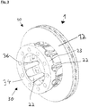
- FIG. 2 and the FIG. 3 each show a perspective view of a brake disc 1 according to the invention, in principle, the two representation of an embodiment or different embodiments of different Show directions.
- the friction section 10 is formed by an internally ventilated friction ring which has two friction surfaces 12.
- the friction portion 10 is connected to the connecting portion 30 via the fingers 22 forming the intermediate portion 20 together with the plate-shaped ridges 23.
- the fingers 22 in this case had a convex outer contour in the direction and in the region next to the rotation axis A.
- the fingers 22 form a recess on the radially outer periphery of the connecting portion 30, as shown in FIG FIG. 2 right and in the FIG. 3 can be seen on the left.
- the primary mounting surface 32 of the connecting portion 30 has mounting holes 36 for attachment. Radially outward, the primary mounting surface 32 is limited by the webs 23 and the fingers 22.
- the mounting holes 36 extend from the primary mounting surface 32 to the secondary mounting surface 34 in the direction of the rotational axis A.
Landscapes
- Engineering & Computer Science (AREA)
- General Engineering & Computer Science (AREA)
- Mechanical Engineering (AREA)
- Braking Arrangements (AREA)
Abstract
Description
- Die Erfindung betrifft eine Bremsscheibe, insbesondere für den Einsatz in Nutzfahrzeugen.
- Bremsscheiben sind bereits aus dem Stand der Technik bekannt, diese dienen dazu, eine Achse, mit welcher die Bremsscheibe drehfest verbunden ist, abzubremsen. Problematisch ist dabei, insbesondere bei Nutzfahrzeugen, dass für eine sichere Kraftübertragung die Anschlussbereiche an eine Radnabe sich weit radial nach außen erstrecken müssen, sodass die Bremsscheibe zum einen ein hohes Gewicht und zum anderen einen großen Bauraumbedarf aufweist.
- Es ist daher die Aufgabe der vorliegenden Erfindung, eine leichte Bremsscheibe, insbesondere für Nutzfahrzeuge, bereitzustellen, welche nur einen geringen Bauraumbedarf aufweist.
- Diese Aufgabe wird mittels einer Bremsscheibe gemäß dem Anspruch 1 und mittels einer Bremsanordnung gemäß Anspruch 10 gelöst. Bevorzugte Merkmale und Ausführungen ergeben sich aus den Unteransprüchen.
- Erfindungsgemäß umfasst eine Bremsscheibe, insbesondere für Nutzfahrzeuge, einen Reibabschnitt, einen Zwischenabschnitt und einen Verbindungsabschnitt, wobei die Bremsscheibe dazu ausgelegt ist, um eine Rotationsachse zu rotieren oder rotierbar gelagert zu sein, wobei der Reibabschnitt zumindest eine Reibfläche aufweist, welche dazu ausgelegt ist, mit einem Reibbelag in Kontakt zu treten, sodass ein Bremsmoment um die Rotationsachse entsteht oder entstehen kann, wobei der Zwischenabschnitt mehrere Finger aufweist, welche sich im Wesentlichen in Richtung der Rotationsachse erstrecken, wobei der Verbindungsabschnitt zumindest eine primäre Montagefläche und eine Vielzahl von Montageöffnungen aufweist, wobei sich die Montageöffnungen von der primären Montagefläche aus erstrecken oder durch diese hindurchragen, wobei die zumindest eine primäre Montagefläche dazu ausgelegt ist, mit einer Radnabe mittelbar oder unmittelbar zu kontaktieren, und wobei die Montageöffnungen dazu ausgelegt sind, Montagemittel aufzunehmen, um die Bremsscheibe an der Radnabe festzulegen und/oder zu verspannen. Die Bremsscheibe ist dabei derart gelagert oder lagerbar, dass diese um die Rotationsachse rotieren kann. Die Rotationsachse ist insbesondere die Achse, um welche die zu bremsende Nabe rotiert. In anderen Worte bedeutet dies, dass die Rotationsachse die Achse sein kann, um welche die Räder, die Achse oder die Welle rotiert, welche mittels der Bremsscheibe gebremst werden soll. Der Reibabschnitt der Bremsscheibe kann dabei ein einzelnes Bauteil sein, oder einstückig mit dem Zwischenabschnitt ausgestaltet sein. Insbesondere weist der Reibabschnitt zumindest eine Reibfläche auf, bevorzugt jedoch zumindest zwei Reibflächen, welche den Reibabschnitt in Richtung der Rotationsachse distal begrenzen können. Die Reibfläche bzw. die Reibflächen sind dazu ausgelegt, mit einem Reibbelag derart in Kontakt zu treten oder in Kontakt treten zu können, dass ein Drehmoment um die Rotationsachse entstehen kann. Der Zwischenabschnitt der Bremsscheibe ist derjenige Bereich der Bremsscheibe, welcher die Finger umfasst. In anderen Worten bedeutet dies, dass die Finger sich bevorzugt lediglich im Zwischenabschnitt befinden. Die Finger sind dabei nicht durch einen Materialabtrag, wie er beispielsweise bei Nuten, Ausnehmungen oder Bohrungen vorliegt, ausgebildet, sondern bevorzugt durch ein Urformverfahren gebildet, wie beispielsweise Gießen oder ein additives Fertigungsverfahren. Alternativ und/oder zusätzlich bevorzugt sind Finger insbesondere dadurch charakterisiert, dass die der Rotationsachse zugewandten und die der Rotationsachse abgewandten Flächen des Fingers nicht parallel zueinander ausgerichtet und/oder ausgebildet sind. Bevorzugt weisen die Finger, insbesondere in einer Schnittebene senkrecht zur Rotationsachse, eine zumindest bereichsweise runde, bevorzugt konkave oder konvexe, Außen- und/oder Innenkontur auf, insbesondere in Richtung und/oder im Bereich nächstliegend zur Rotationsachse. Durch die Verwendung von Fingern kann insbesondere aufgrund des großen Flächenträgheitsmoments und des geringen Kerbwirkungsfaktors eine besonders sichere Anbindung erfolgen. Besonders bevorzugt ist diese Außen- und/oder Innenkontur des Fingers dabei nicht konzentrisch zur Rotationsachse ausgebildet. In anderen Worten bedeutet dies, dass der Mittelpunkt der Krümmung, insbesondere in der Schnittebene senkrecht zur Rotationsachse, der Außen- und/oder der Innenkontur nicht auf der Rotationsachse liegt. Zweckmäßigerweise können die Finger derart ausgestaltet sein, dass sich diese in Richtung der Rotationsachse zumindest bereichsweise verjüngen, sodass Gewicht eingespart werden kann. Die Finger erstrecken sich im Wesentlichen in Richtung der Rotationsachse. Unter im Wesentlichen in Richtung der Rotationsachse ist zu verstehen, dass die Erstreckungsrichtung der Finger einen Winkel von +/- 25°, bevorzugt von +/- 12° und besonders bevorzugt von +/- 4° mit der Rotationsachse bilden. Die Erstreckungsrichtung der Finger bestimmt sich dabei insbesondere durch den Verlauf der Querschnittsschwerpunkte, wobei sich die Querschnittsschwerpunkte des Fingers zweckmäßigerweise in Ebenen bestimmen, welche eine Normale parallel zur Rotationsachse aufweisen. Durch die Finger wird der Reibabschnitt von dem Verbindungsabschnitt in Richtung der Rotationsachse bevorzugt separiert. Besonders bevorzugt dienen insbesondere die distalen Enden bzw. Endabschnitte der Finger zur Drehmoment- und/oder Kraftübertragung von dem Reibabschnitt auf die Finger bzw. von den Fingern auf den Verbindungsabschnitt. Der Verbindungsabschnitt der Bremsscheibe ist dasjenige Bauteil oder Bestandteil der selbigen, welches/r dazu ausgelegt ist, die Bremsscheibe an einer Radnabe direkt oder indirekt festzulegen. Hierzu dient die primäre Montagefläche des Verbindungsabschnitts, sodass ein flächiger Kontakt stattfinden kann. In anderen Worten ist der Verbindungsabschnitt daher dasjenige Bauteil oder Bestandteil der Bremsscheibe, welcher dazu ausgelegt ist, dass Bremsmoment auf die Radnabe über die primäre Montagefläche, insbesondere vollständig, zu übertragen. Die primäre Montagefläche liegt bevorzugt, insbesondere vollständig, in einer Ebene und weist zweckmäßigerweise eine Normale auf, welche sich im Wesentlichen in Richtung der Rotationsachse erstreckt. Die Vielzahl von Montageöffnungen, welche sich, insbesondere parallel zur Rotationsachse, von der primären Montagefläche aus erstrecken, dienen zur Aufnahme von Montagemitteln, wie beispielsweise Schrauben, Bolzen oder Nieten. Die Montagemittel sind dabei dazu ausgelegt, die Bremsscheibe an einer Radnabe festzulegen und/oder zu verspannen. Die Radnabe selbst kann beispielsweise durch einen Teil eines Radlagergehäuses, einer bekannten Nabe, einem Teil einer Welle oder einem Teil einer Achse gebildet sein.
- Bevorzugt verfügt der Verbindungsabschnitt über einen Zentrierkragen. Der Zentrierkragen kann beispielsweise durch einen Vorsprung in Richtung der Rotationsachse gebildet sein. Durch die Verwendung eines Zentrierkragens kann die Montage der Bremsscheibe erleichtert werden, sodass Kosten gespart werden können. Besonders bevorzugt erstreckt sich der zumindest eine Zentrierkragen von der primären Montagefläche aus und/oder begrenzt diese zur Rotationsachse hin, um eine kompakte Bremsscheibe zu erreichen.
- Zweckmäßigerweise weist der Zwischenabschnitt 5 bis 17, bevorzugt 7 bis 14 und besonders bevorzugt 9 bis 11 Finger auf. Durch die Ausgestaltung des Zwischenbereichs mit 5 bis 17 Fingern, kann erreicht werden, dass eine sichere Kraft- bzw. Momentenübertragung zwischen Reibabschnitt und Verbindungsabschnitt erfolgt. Bei der Verwendung von 7 bis 14 Fingern wird ein besonders guter Kompromiss zwischen einer zu vermeidenden Unwucht und einem geringen Gewicht der Bremsscheibe erreicht. Um eine besonders homogene Spannungsverteilung im Verbindungsabschnitt zu erreichen, ist es besonders bevorzugt, 9 bis 11 Finger im Zwischenabschnitt zu verwenden. Durch die homogene Spannungsverteilung können lokale Spannungsspitzen und die damit einhergehenden Nachteile - wie z.B. Rissbildung - vermieden werden.
- Bevorzugt weist der Verbindungsabschnitt eine sekundäre Montagefläche auf, welche dazu ausgelegt ist, dass an der sekundären Montagefläche eine Felge angeordnet oder anordenbar ist. Hierdurch kann eine besonders kompakte Bauweise der Bremsscheibe erreicht werden. Die sekundäre Montagefläche kann dabei ebenfalls oder zusätzlich einen Zentrierkragen aufweisen, um die Montage der Felge zu erleichtern. Bevorzugt sind die primäre und die sekundäre Montagefläche im Wesentlichen parallel zu einander angeordnet, wobei die Montageöffnungen sowohl die primäre als auch die sekundäre Montagefläche durchragen bzw. sich von diesen aus erstrecken. Hierdurch kann erreicht werden, dass die Bremsscheibe mit denselben Montagemitteln festgelegt werden kann wie die zu montierende Felge, sodass Bauteile und Kosten gespart werden können. Besonders bevorzugt bilden die sekundäre und primäre Montagefläche dabei einen in radialer Richtung nach Innen oder Außen ragenden Montageflansch des Verbindungsabschnitts zumindest bereichsweise aus, sodass ein kompakter Verbindungsabschnitt erreicht wird.
- Vorteilhafterweise erstrecken sich die Finger vom Verbindungsabschnitt in eine negative Richtung der Rotationsache. Die negative Richtung der Rotationsachse ist dabei die Richtung der Rotationsache, welche von der primären Montagefläche zur zumindest einen Reibfläche weist oder die negative Richtung der Rotationsachse kann zusätzlich oder alternativ auch durch die Richtung der Rotationsachse gebildet sein, welche von der sekundären Montagefläche zur primären Montagefläche weist. Beispielsweise erstrecken sich die Finger dabei zu zumindest 4 cm, bevorzugt zu zumindest 8 cm in Richtung der Rotationsachse, insbesondere in Richtung der negativen Rotationsachse.
- Besonders bevorzugt ist der Abstand in Richtung der Rotationsachse der primären Montagefläche zur nächst liegenden Reibfläche größer als die maximale Erstreckung des Reibabschnitts in Richtung der Rotationsachse. Hierdurch kann eine besonders geringe thermische Belastung der Anbindung, insbesondere der verwendeten Montagemittel, der Bremsscheibe erreicht werden, sodass eine besonders sichere Festlegung der Bremsscheibe erfolgen kann.
- Zweckmäßigerweise ist der Zwischenabschnitt einstückig mit dem Verbindungabschnitt ausgebildet. Hierdurch kann eine hohe Belastbarkeit sichergestellt werden, sodass eine sichere Drehmomentübertragung stattfinden kann. Bevorzugt ist es, wenn der Reibabschnitt dabei ein separates Bauteil zu dem Bauteil darstellt, welches den Zwischenabschnitt und den Verbindungsabschnitt umfasst. Durch diese mehrteilige Ausgestaltung der Bremsscheibe, insbesondere des Reibabschnitts, kann sichergestellt werden, dass der Wärmeübergang zwischen dem Reibabschnitt und dem Verbindungsabschnitt erschwert wird, sodass die Wärmebelastung der Radnabe gering gehalten wird und insbesondere die Radlager durch den reibungsbedingten Wärmeeintrag nicht negativ beeinflusst werden. Alternativ bevorzugt kann auch der Reibabschnitt einstückig mit dem Verbindungsabschnitt und/oder dem Zwischenabschnitt ausgebildet sein. Hierdurch wird nicht nur die Sicherheit der Drehmomentübertragung gesteigert, sondern zusätzlich kann auch die Wärmeabfuhr von der Reibfläche erhöht werden, sodass die Bremsleistung gesteigert werden kann. Einstückigkeit bedeutet dabei insbesondere, dass die Bauteile nicht durch ein, insbesondere nachträgliches, Fügeverfahren, wie beispielsweise Schweißen, stoffschlüssig aneinander gefügt sein dürfen.
- Vorteilhafterweise weist der Zwischenabschnitt eine Vielzahl von Übertragungsstrukturen auf, welche insbesondere in eine radiale Richtung weisen, wobei der Reibabschnitt eine Vielzahl von Transmissionsstrukturen aufweist, wobei die Übertragungsstrukturen derart mit komplementären Transmissionsstrukturen in Eingriff stehen oder bringbar sind, dass ein Drehmoment um die Rotationsachse, insbesondere formschlüssig, übertragbar ist. Die Übertragungsstrukturen sind Elemente, wie beispielsweise Ausnehmungen oder Vorsprünge, welche zur Drehmomentübertragung auf die komplementären Transmissionsstrukturen ausgelegt sind. Komplementär ist eine Übertragungsstruktur insbesondere dann zu einer Transmissionsstruktur, wenn diese beiden Strukturen, bevorzugt unmittelbar, miteinander kontaktieren. Die radiale Richtung ist diejenige Richtung, welche radial von der Rotationsachse weg weist. Unter einem in radiale Richtung weisen kann verstanden werden, dass die Übertragungsstrukturen sich von den Fingern, insbesondere dessen Endabschnitten, aus in radiale Richtung erstrecken. Beispielsweise bilden die Übertragungsstrukturen dabei Zähne, welche in komplementäre Transmissionsstrukturen, welche insbesondere durch Vertiefungen gebildet sein können, formschlüssig eingreifen. Durch diese Drehmomentübertragung wird erreicht, dass ein hohes Drehmoment sicher übertragen werden kann. Bevorzugt greifen die Übertragungsstrukturen dabei derart in die komplementären Transmissionsstrukturen ein, dass eine Verlagerung des Zwischenabschnitts relativ zum Reibabschnitt in Richtung der Rotationsachse in positive und/oder negative Richtung und/oder in die radiale Richtung formschlüssig durch die Interaktion der Transmissionsstrukturen mit den Übertragungsstrukturen verhindert ist oder verhinderbar ist. Dies kann insbesondere durch ein Eingießen des Zwischenabschnitts in den Reibabschnitt oder des Reibabschnitts in den Zwischenabschnitt erreicht werden. Durch diese Maßnahme kann insbesondere das Auftreten von lokalen verschleißbedingten Dickenunterschieden reduziert bzw. verhindert werden, sodass Vibrationsursachen reduziert werden. Besonders vorteilhaft ist es, wenn der Reibabschnitt um die Übertragungsstrukturen des Zwischenabschnitts herum gegossen ist.
- Bevorzugt ist ein Abstand des Verbindungsabschnitts zur Rotationsachse größer als ein Abstand, der zumindest einen Reibfläche zur Rotationsachse. Der Abstand des Verbindungsabschnitts zur Rotationsachse ist hierbei der maximal mögliche Abstand des Verbindungsabschnitts zur Rotationsachse oder alternativ der mittlere Abstand des Verbindungsabschnitts zur Rotationsachse. Der maßgebliche Abstand der zu mindestens einen Reibfläche zur Rotationsachse ist in diesem Zusammenhang der minimalst mögliche Abstand von der Reibfläche zur Rotationsachse. Durch diese Art der Ausgestaltung der Bremsscheibe wird eine besonders kompakte Bauweise realisiert. Bevorzugt liegt das Verhältnis aus dem Abstand der Reibfläche zur Rotationsachse zum Abstand des Verbindungsabschnitts zur Rotationsachse in einem Bereich von 0,7-0,9. Hierdurch kann die Leistung der Bremse dadurch gesteigert werden, dass die Reibfläche eine besonders große Erstreckung in die radiale Richtung aufweisen kann, ohne das die Anbindung der Bremsscheibe negativ beeinflusst wird.
- Zweckmäßigerweise ist der Lochkreisdurchmesser der Montageöffnungen kleiner als der Abstand der zu mindestens einen Reibfläche von der Rotationsachse. Hierdurch kann ein geringer Bauraumbedarf der Bremsscheibe erreicht werden. Der Lochkreisdurchmesser ist dabei der gemittelte oder maximale Abstand der Montageöffnungen zu der Rotationsachse. Der Abstand der einzelnen Montageöffnungen bestimmt sich dabei durch den gedachten bzw. idealisierte Volumenschwerpunkt der Montageöffnung zur Rotationsachse in Richtung der radialen Richtung.
- Bevorzugt liegt das Verhältnis aus dem Abstand von der primären Montagefläche bis zur nächstliegenden Reibfläche in Richtung der Rotationsachse zum Lochkreisdurchmesser in einem Verhältnis von 0,2 bis 1,1, bevorzugt in einem Verhältnis von 0,3 bis 0,9 und besonders bevorzugt in einem Verhältnis von 0,5 bis 0,75. Bei einem Verhältnis von 0,2 bis 1,1 kann eine besonders mechanisch belastbare Anbindung des Reibabschnitts erreicht werden. Bei einem Verhältnis von 0,3 bis 0,9 hat die Anmelderin überraschenderweise herausgefunden, dass hierdurch die Neigung zur Rissbildung im Anschlussbereich der Finger an den Verbindungsabschnitt minimiert werden kann. Bei einem Verhältnis von 0,5 bis 0,75 kann eine geringe relative Verdrehung zwischen dem Anschlussabschnitt und dem Reibabschnitt realisiert werden, was insbesondere in einem vom Benutzer als Vorteilhaft empfundenen Bremsverhalten mündet.
- Zweckmäßigerweise begrenzen die Finger die primäre Montagefläche zumindest bereichsweise, bevorzugt vollständig, in die radiale Richtung nach außen. Durch diese räumliche Nähe der Finger zu der primären Montagefläche wird erreicht, dass nur geringe Bereiche des Anschlussabschnitts durch die Drehmomentübertragung von der Bremsscheibe auf die Radnabe bzw. Felge belastet werden, sodass Material gespart werden kann. Zusätzlich wird hierdurch auch noch eine besonders kompakte Bauweise der Bremsscheibe ermöglicht. Unter begrenzen kann insbesondere verstanden werden, dass die Finger eine Kante der primären Montagefläche ausbilden, welche ohne das Vorhandensein der Finger nicht existieren würde.
- Bevorzugt ist der minimalste Abstand der Finger zur Rotationsachse kleiner als der maximale Abstand der Montageöffnungen zur Rotationsachse. Hierdurch kann eine kompakte Bauweise der Bremsscheibe erzielt werden. Maßgeblich für die Bestimmung des Abstands der Finger zur Rotationsachse ist dabei der Bereich der Finger, mit welchem diese am Anschlussabschnitt festgelegt sind. Der maximale Abstand der Montageöffnungen bestimmt sich insbesondere durch den maximal möglichen Abstand der Montageöffnungen zur Rotationsachse in Richtung der radialen Richtung.
- Zweckmäßigerweise ist der minimalste Abstand der Finger zur Rotationsachse kleiner als der Lochkreisdurchmesser. Hierdurch kann eine besonders bauraumsparende Bremsscheibe erreicht werden.
- Besonders bevorzugt ist der minimalste Abstand der Finger zur Rotationsachse kleiner als der minimalste Abstand der Montageöffnung zur Rotationsachse. Der Abstand der Finger zur Rotationsachse bestimmt sich insbesondere, wie bereits beschrieben, durch den Abstand des Anschlussbereichs der Finger an den Anschlussabschnitt in Richtung der radialen Richtung. Durch diese Ausgestaltung der Bremsscheibe kann nicht nur eine besonders kompakte Bauweise der Bremsscheibe erreicht werden, sondern zusätzlich kann hierdurch realisiert werden, dass die Finger bei einem Versagen der Montagemittel als Notdrehmomentübertragungseinheiten fungieren können, sodass die Sicherheit der Bremsscheibe erhöht wird. Besonders bevorzugt ist es, wenn die Finger die primäre Montagefläche dabei in nicht zusammenhängende Bereiche unterteilt. Hierdurch kann der vorhandene Bauraum optimal ausgenutzt werden. Unter "nicht zusammenhängende Bereiche" ist dabei in diesem Zusammenhang zu verstehen, dass die primäre Montagefläche in unterschiedliche separate Flächen - bedingt durch die Finger - unterteilt wird.
- Zweckmäßigerweise sind zumindest zwei in Umfangsrichtung benachbarte Finger durch einen Steg miteinander verbunden. Hierdurch kann die Torsionssteifigkeit der Bremsscheibe erhöht werden. Die Umfangsrichtung bildet dabei mit der Rotationsachse und der radialen Richtung ein Zylinderkoordinatensystem aus, wobei die Umfangsrichtung die Polare- bzw. Winkelrichtung darstellt bzw. bildet. Die Stege können insbesondere durch Stäbe und/oder Platten gebildet sein, wobei es besonders zweckmäßig ist, wenn die Stege zumindest eine Erstreckung in Richtung der Rotationsachse von 2,5 cm aufweisen. Bevorzugt sind dabei alle Finger der Bremsscheibe in Umfangsrichtung jeweils über einen Steg mit den benachbarten Fingern verbunden. Besonders bevorzugt sind die Stege nicht nur mit den Fingern sondern auch mit der primären Montagefläche verbunden. Insbesondere kann es dabei zweckmäßig sein, wenn die Stege einstückig mit den Fingern und/oder mit dem Verbindungsabschnitt ausgebildet sind, um eine sichere Kraft- und/oder Momentenübertragung zu erreichen.
- Vorteilhafterweise begrenzt der zumindest eine Steg die primäre Montagefläche zumindest bereichsweise in die radiale Richtung nach außen. Hierdurch wird die primäre Montagefläche (oder die einzelnen Subflächen der primären Montagefläche) gegen das Eintreten von Verunreinigung geschützt. Zusätzlich wird hierdurch auch noch die Torsions- und Biegesteifigkeit der Bremsscheibe erhöht, sodass auch hohe Bremsmomente, wie sie insbesondere bei Nutzfahrzeugen auftreten, sicher übertragen werden können. Besonders bevorzugt ist es, um eine hohe Torsionssteifigkeit zu erreichen, wenn die Finger und die Stege, die die Finger miteinander verbinden, dabei einen geschlossenen Ring bilden. In anderen Worten bedeutet dies, dass es einen, insbesondere kreisförmigen, Ring gibt, welcher die Rotationsachse vollständig umgibt und lediglich durch die Finger und die Stege gebildet ist.
- Bevorzugt weisen die Finger eine veränderliche Querschnittsfläche entlang der Rotationsachse auf. Hierdurch kann eine besonders leichte Bremsscheibe durch Anpassung der Querschnittsfläche der Finger an die auftretenden Belastungen erreicht werden. Besonders bevorzugt nimmt die Querschnittsfläche insbesondere in negativer Richtung der Rotationsachse zumindest Abschnittsweise, insbesondere über die Hälfte der Erstreckung der Finger in Richtung der Rotationsachse, ab. Die Querschnittsfläche bestimmt sich dabei in einer Schnittebene, deren Normale insbesondere parallel zur Rotationsachse ist. Unter einer veränderlichen Querschnittsfläche ist zu verstehen, dass die Querschnittsfläche eine, bevorzugt kontinuierliche, Veränderung entlang der Rotationsachse aufweist.
- Erfindungsgemäß umfasst eine Bremsenanordnung, insbesondere für Nutzfahrzeuge, eine Bremsscheibe, wie sie bereits beschrieben wurde, eine Radnabe und eine Radachse, wobei die primäre Montagefläche der Bremsscheibe mit der Radnabe in Kontakt treten kann, ohne dass die Radnabe relativ zur Achse verlagert werden muss. In anderen Worten bedeutet dies, dass es sich bei der Bremsscheibe und der Radnabe um eine Anordnung handelt, bei der die Bremsscheibe demontiert werden kann, ohne dass die Radnabe verlagert oder demontiert werden muss. Hierdurch kann die Montage derart vereinfacht werden, dass, insbesondere im Nutzfahrzeugbereich, Kosten eingespart werden können.
- Weitere Vorteile und Merkmale der vorliegenden Erfindung ergeben sich aus der nachfolgenden Beschreibung mit Bezug auf die Figuren. Einzelne Merkmale der dargestellten Ausführungsformen können dabei auch in anderen Ausführungsformen eingesetzt werden, sofern dies nicht ausdrücklich ausgeschlossen wurde.
- Es zeigen:
-
Figur 1 einen Schnitt durch eine erfindungsgemäße Bremsscheibe und einen Teil einer erfindungsgemäßen Bremsenanordnung; -
Figur 2 eine perspektivische Ansicht einer erfindungsgemäßen Bremsscheibe; -
Figur 3 eine weitere perspektivische Ansicht einer erfindungsgemäßen Bremsscheibe. - Die
Figur 1 zeigt eine erfindungsgemäße Bremsscheibe 1, welche über einen Reibabschnitt 10, einen Zwischenabschnitt 20 und einen Verbindungsabschnitt 30 verfügt. Der Reibabschnitt 10 ist in der dargestellten Ausführungsform durch einen innenbelüfteten Reibring gebildet, welcher zwei parallele Reibflächen 12 umfasst. Die Reibflächen 12 weisen dabei einen Abstand R12 zur Rotationsachse A auf. Der Zwischenabschnitt 20 ist in der dargestellten Ausführungsform durch die Finger 22 und die Stege 23 gebildet, wobei in der dargestellten Schnittansicht lediglich ein Steg 23 erkennbar ist. Der Zwischenabschnitt 20 ist einstückig mit dem Verbindungsabschnitt 30 ausgeführt, wobei der Verbindungsabschnitt 30 eine primäre Montagefläche 32, eine sekundäre Montagefläche 34 und einen Abstand zur Rotationsachse R30 in Richtung der radialen Richtung R aufweist. Die primäre Montagefläche 32 ist von der nächstliegenden Reibfläche 12 in Richtung der Rotationsache A um den Abstand A12 beabstandet. Zur Festlegung der Bremsscheibe 1 an einer Radnabe 40 verfügt die primäre Montagefläche 32 über Montageöffnungen 36, welche sich bis zu der sekundären Montageflächen 34 erstrecken, und wobei durch die Montageöffnungen 36 Montagemittel 50 geführt sind. Um eine Zentrierung der Bremsscheibe 1 auf der Radnabe 40 zu erleichtern, verfügt der Verbindungsabschnitt 30 über einen Zentrierkragen 38, welche die primäre Montagefläche 32 in radialer Richtung R nach innen begrenzt. Die radiale Richtung R, die Rotationsachse A und die Umfangsrichtung U bilden dabei ein rechtshändiges Zylinderkoordinatensystem miteinander. Die Montageöffnungen 36 weisen einen Lochkreisdurchmesser D36 zur Rotationsachse A auf. Um ein Drehmoment um die Rotationsachse A von dem Reibabschnitt 10 auf den Zwischenabschnitt 20 zu übertragen, verfügt der Reibabschnitt 10 über Transmissionsstrukturen 14, in welche komplementäre Übertragungsstrukturen 24 formschlüssig eingreifen. Die Übertragungsstrukturen 24 sind dabei in den Endabschnitten der Finger 22 angeordnet bzw. einstückig mit den Fingern 22 ausgebildet. Die Transmissionsstrukturen 14 und die Übertragungsstrukturen 24 erstrecken sich dabei in die radiale Richtung R. - Die
Figur 2 und dieFigur 3 zeigen jeweils eine perspektivische Ansicht einer erfindungsgemäßen Bremsscheibe 1, prinzipiell können die beiden Darstellung eine Ausführungsform oder verschiedene Ausführungsformen aus unterschiedlichen Blickrichtungen zeigen. Der Reibabschnitt 10 ist durch einen innenbelüfteten Reibring gebildet, welcher zwei Reibflächen 12 aufweist. Der Reibabschnitt 10 ist über die Finger 22, welche den Zwischenabschnitt 20 zusammen mit den plattenförmigen Stegen 23 bilden, mit dem Verbindungsabschnitt 30 verbunden. Die Finger 22 wiesen dabei eine konvexe Außenkontur in Richtung und im Bereich nächstliegend zur Rotationsachse A auf. Zusätzlich bilden die Finger 22, um Gewicht zu sparen, eine Aussparung an dem Radial äußeren Umfang des Verbindungsabschnitts 30 aus, wie es in derFigur 2 rechst und in derFigur 3 links zu erkennen ist. Die primäre Montagefläche 32 des Verbindungsabschnitts 30 verfügt über Montageöffnungen 36 zur Festlegung. Radial nach außen ist die primäre Montagefläche 32 dabei durch die Stege 23 und die Finger 22 begrenzt. Die Montageöffnungen 36 erstrecken sich von der primären Montagefläche 32 bis zu der sekundären Montagefläche 34 in Richtung der Rotationsachse A. -
- 1
- - Bremsscheibe
- 10
- - Reibabschnitt
- 12
- - Reibfläche
- 14
- - Transmissionsstruktur
- 20
- - Zwischenabschnitt
- 22
- - Finger
- 23
- - Steg
- 24
- - Übertragungsstruktur
- 30
- - Verbindungsabschnitt
- 32
- - primäre Montagefläche
- 34
- - sekundäre Montagefläche
- 36
- - Montageöffnung
- 38
- - Zentrierkragen
- 40
- - Radnabe
- 50
- - Montagemittel
- A
- - Rotationsachse
- A12
- - Abstand von der primären Montagefläche zur Reibfläche in Richtung der Rotationsachse
- D36
- - Lochkreisdurchmesser
- R
- - radiale Richtung
- R12
- - Abstand der Reibfläche zur Rotationsachse
- R30
- - Abstand des Verbindungsabschnitts zur Rotationsachse
- U
- - Umfangsrichtung
Claims (15)
- Bremsscheibe (1), insbesondere für Nutzfahrzeuge, umfassend einen Reibabschnitt (10), einen Zwischenabschnitt (20) und einen Verbindungsabschnitt (30),
wobei die Bremsscheibe (1) dazu ausgelegt ist, um eine Rotationsachse (A) zu rotieren oder rotierbar gelagert zu sein,
wobei der Reibabschnitt (10) zumindest eine Reibfläche (12) aufweist, welche dazu ausgelegt ist, mit einem Reibbelag in Kontakt zu treten, sodass ein Bremsmoment um die Rotationsache (A) entsteht oder entstehen kann, wobei der Zwischenabschnitt (20) mehrere Finger (22) aufweist, welche sich im Wesentlichen in Richtung der Rotationsachse (A) erstrecken,
wobei der Verbindungsabschnitt (30) zumindest eine primäre Montagefläche (32) und eine Vielzahl von Montageöffnungen (36) aufweist,
wobei sich die Montageöffnungen (36) von der primären Montagefläche (32) aus erstrecken,
wobei die zumindest eine primäre Montagefläche (32) dazu ausgelegt ist, mit einer Radnabe (40) mittelbar/unmittelbar zu kontaktieren, und wobei die Montageöffnungen (36) dazu ausgelegt sind, Montagemittel (50) aufzunehmen, um die Bremsscheibe (1) an der Radnabe (40) festzulegen. - Bremsscheibe (1) gemäß Anspruch 1,
wobei der Zwischenabschnitt (20) 5 bis 17, bevorzugt 7 bis 14 und besonders bevorzugt 9 bis 11 Finger (22) aufweist. - Bremsscheibe (1) gemäß einem der vorhergehenden Ansprüche,
wobei der Verbindungsabschnitt (30) eine sekundäre Montagefläche (34) aufweist, welche dazu ausgelegt ist, dass an der sekundären Montagefläche (34) eine Felge (60) angeordnet ist oder anordenbar ist. - Bremsscheibe (1) gemäß einem der vorhergehenden Ansprüche,
wobei sich die Finger (22) vom Verbindungsabschnitt (30) in eine negative Richtung der Rotationsache (A) erstrecken. - Bremsscheibe (1) gemäß einem der vorhergehenden Ansprüche,
wobei der Zwischenabschnitt (20) einstückig mit dem Verbindungsabschnitt (30) ausgebildet ist. - Bremsscheibe (1) gemäß einem der vorhergehenden Ansprüche,
wobei der Zwischenabschnitt (20) eine Vielzahl von Übertragungsstrukturen (24) aufweist, welche insbesondere in eine radiale Richtung (R) weisen, wobei der Reibabschnitt (10) eine Vielzahl von Transmissionsstrukturen (14) aufweist,
wobei die Übertragungsstrukturen (24) derart mit komplementären Transmissionsstrukturen (14) in Eingriff stehen oder bringbar sind, dass ein Drehmoment um die Rotationsachse (A), insbesondere formschlüssig, übertragbar ist. - Bremsscheibe (1) gemäß einem der vorhergehenden Ansprüche,
wobei ein Abstand (R30) des Verbindungsabschnitts (30) zur Rotationsachse (A) größer ist als ein Abstand (R12) der zumindest einen Reibfläche (12) zur Rotationsachse (A). - Bremsscheibe (1) gemäß einem der vorhergehenden Ansprüche,
wobei der Lochkreisdurchmesser (D36) der Montageöffnungen (36) kleiner ist als der Abstand (R12) der zumindest einen Reibflächen (12) von der Rotationsachse (A). - Bremsscheibe (1) gemäß Anspruch 8,
wobei das Verhältnis aus dem Abstand (A12) von der primären Montagefläche (32) bis zur nächstliegenden Reibfläche (12) in Richtung der Rotationsache (A) zum Lochkreisdurchmesser (D36) in einem Verhältnis von 0,2 bis 1,1, bevorzugt in einem Verhältnis 0,3 bis 0,9 und besonders bevorzugt in einem Verhältnis von 0,5 bis 0,75, liegt. - Bremsscheibe (1) gemäß einem der vorhergehenden Ansprüche,
wobei die Finger (22) die primäre Montagefläche (32) zumindest bereichsweise in die radiale Richtung (R) nach außen begrenzen. - Bremsscheibe (1) gemäß einem der vorhergehen Ansprüche,
wobei der minimalste Abstand der Finger (22) zur Rotationsachse (A) kleiner ist als der maximale Abstand der Montageöffnungen (36) zur Rotationsachse (A). - Bremsscheibe (1) gemäß einem der vorhergehenden Ansprüche,
wobei der minimalste Abstand der Finger (22) zur Rotationsachse (A) kleiner ist als der Lochkreisdurchmesser (D36). - Bremsscheibe (1) gemäß einem der vorhergehen Ansprüche,
wobei der minimalste Abstand der Finger (22) zur Rotationsachse (A) kleiner ist als der minimalste Abstand der Montageöffnungen (36) zur Rotationsachse (A). - Bremsscheibe (1) gemäß einem der vorhergehenden Ansprüche,
wobei zumindest zwei in Umfangsrichtung (U) benachbarte Finger (22) durch einen Steg (23) miteinander verbunden sind. - Bremsanordnung umfassend eine Bremsscheiben (1) nach einem der vorhergehenden Ansprüche, eine Radnabe (40) und eine Achse,
wobei die primäre Montagefläche (32) der Bremsscheibe (1) mit der Radnabe (40) in Kontakt treten kann, ohne dass die Radnabe (40) relativ zur Achse verlagert werden muss.
Priority Applications (1)
| Application Number | Priority Date | Filing Date | Title |
|---|---|---|---|
| PL18211328T PL3499074T3 (pl) | 2017-12-18 | 2018-12-10 | Tarcza hamulcowa |
Applications Claiming Priority (1)
| Application Number | Priority Date | Filing Date | Title |
|---|---|---|---|
| DE102017130290.5A DE102017130290B4 (de) | 2017-12-18 | 2017-12-18 | Bremsscheibe |
Publications (2)
| Publication Number | Publication Date |
|---|---|
| EP3499074A1 true EP3499074A1 (de) | 2019-06-19 |
| EP3499074B1 EP3499074B1 (de) | 2020-09-09 |
Family
ID=64664153
Family Applications (1)
| Application Number | Title | Priority Date | Filing Date |
|---|---|---|---|
| EP18211328.2A Active EP3499074B1 (de) | 2017-12-18 | 2018-12-10 | Bremsscheibe |
Country Status (3)
| Country | Link |
|---|---|
| EP (1) | EP3499074B1 (de) |
| DE (1) | DE102017130290B4 (de) |
| PL (1) | PL3499074T3 (de) |
Cited By (1)
| Publication number | Priority date | Publication date | Assignee | Title |
|---|---|---|---|---|
| IT202300024927A1 (it) * | 2023-11-23 | 2025-05-23 | Stellantis Europe Spa | "disco freno provvisto di una pluralità di elementi aerodinamici per sviluppare un effetto di ventilazione" |
Families Citing this family (1)
| Publication number | Priority date | Publication date | Assignee | Title |
|---|---|---|---|---|
| DE102024116446B3 (de) * | 2024-06-12 | 2025-07-31 | Saf-Holland Gmbh | Radnabe, Bremsscheibe und Radnabensystem |
Citations (3)
| Publication number | Priority date | Publication date | Assignee | Title |
|---|---|---|---|---|
| DE19929391A1 (de) * | 1999-06-28 | 2001-01-04 | Sauer Achsenfab | Bremsscheibe |
| DE102012215247A1 (de) * | 2012-08-28 | 2014-03-06 | Schaeffler Technologies AG & Co. KG | Radlageranordnung umfassend eine Bremsscheibe mit Radzentrierung |
| FR3001015A1 (fr) * | 2013-01-14 | 2014-07-18 | Peugeot Citroen Automobiles Sa | Disque de frein comportant une couronne surmoulee sur le moyeu en tole |
Family Cites Families (7)
| Publication number | Priority date | Publication date | Assignee | Title |
|---|---|---|---|---|
| US2765881A (en) | 1949-12-09 | 1956-10-09 | Raymond C Pierce | Brake rotor |
| GB1027686A (en) | 1962-04-03 | 1966-04-27 | Girling Ltd | Improvements in disc brakes |
| DE3107124A1 (de) | 1981-02-26 | 1982-09-09 | Alfred Teves Gmbh, 6000 Frankfurt | Bremsscheibe fuer eine scheibenbremse |
| DE3120021C2 (de) | 1981-05-20 | 1987-07-09 | Daimler-Benz Ag, 7000 Stuttgart | Anordnung zur Radkühlung an Kraftfahrzeugen |
| DE102004045327A1 (de) | 2004-09-16 | 2006-03-23 | Georg Fischer Fahrzeugtechnik Ag | Bremsscheibenanordung für Fahrzeugräder |
| US20080060890A1 (en) | 2006-08-24 | 2008-03-13 | Bendix Spicer Foundation Brake Llc | Flexibly mounted disc brake rotor for pneumatic, electromotive, and/or hydraulic disc brakes |
| DE102008047625B4 (de) | 2008-09-17 | 2015-04-30 | Knorr-Bremse Systeme für Nutzfahrzeuge GmbH | Innenbelüftete Bremsscheibe |
-
2017
- 2017-12-18 DE DE102017130290.5A patent/DE102017130290B4/de active Active
-
2018
- 2018-12-10 PL PL18211328T patent/PL3499074T3/pl unknown
- 2018-12-10 EP EP18211328.2A patent/EP3499074B1/de active Active
Patent Citations (3)
| Publication number | Priority date | Publication date | Assignee | Title |
|---|---|---|---|---|
| DE19929391A1 (de) * | 1999-06-28 | 2001-01-04 | Sauer Achsenfab | Bremsscheibe |
| DE102012215247A1 (de) * | 2012-08-28 | 2014-03-06 | Schaeffler Technologies AG & Co. KG | Radlageranordnung umfassend eine Bremsscheibe mit Radzentrierung |
| FR3001015A1 (fr) * | 2013-01-14 | 2014-07-18 | Peugeot Citroen Automobiles Sa | Disque de frein comportant une couronne surmoulee sur le moyeu en tole |
Cited By (2)
| Publication number | Priority date | Publication date | Assignee | Title |
|---|---|---|---|---|
| IT202300024927A1 (it) * | 2023-11-23 | 2025-05-23 | Stellantis Europe Spa | "disco freno provvisto di una pluralità di elementi aerodinamici per sviluppare un effetto di ventilazione" |
| WO2025109428A1 (en) * | 2023-11-23 | 2025-05-30 | Stellantis Europe S.P.A. | Brake disc provided with a plurality of aerodynamic elements for developing a ventilation effect |
Also Published As
| Publication number | Publication date |
|---|---|
| DE102017130290A1 (de) | 2019-06-19 |
| DE102017130290B4 (de) | 2022-04-28 |
| PL3499074T3 (pl) | 2021-03-08 |
| EP3499074B1 (de) | 2020-09-09 |
Similar Documents
| Publication | Publication Date | Title |
|---|---|---|
| EP3022458B1 (de) | Bremsscheiben- /nabenverbindung | |
| DE60105206T2 (de) | Scheibe aus verbundwerkstoff für eine scheibenbremse | |
| DE102013107561B4 (de) | Differentialflanschanordnung, Drehmomentübertragungsdifferentialvorrichtung und Differentialanordnung mit Drehsicherungsschlitzen | |
| EP3655257B1 (de) | Radnabe, eine bremsscheibe, ein befestigungsmittel und ein system aus radnabe, bremsscheibe und befestigungsmittel | |
| DE102008005169A1 (de) | Bremsscheibe | |
| DE102019213751A1 (de) | Gebaute Verbundbremstrommel für ein Kraftfahrzeug | |
| DE102018211376B4 (de) | Rotorträger für eine elektrische Maschine | |
| DE102012224468A1 (de) | Bremsscheibe für ein fahrzeug | |
| EP3499074B1 (de) | Bremsscheibe | |
| EP3655256B1 (de) | Radnabe und ein system aus radnabe und bremselement | |
| EP3218208B1 (de) | Elastisches rad für ein schienenfahrzeug | |
| EP3685067B1 (de) | Mehrteilige bremsscheibe | |
| EP3864316B1 (de) | Bremsscheibenanordnung | |
| EP3212436B1 (de) | Schienenrad und schienenfahrzeug | |
| EP3695133B1 (de) | Mehrteilige bremstrommel | |
| WO2017186867A1 (de) | Bremsscheibe für ein fahrzeug | |
| EP3655677B1 (de) | Radnabe, system aus einer bremsscheibe und einer radnabe und ein verfahren zur montage einer bremsscheibe an einer radnabe | |
| EP3685066B1 (de) | Mehrteiliger bremsenrotor | |
| DE1836832U (de) | Bremsscheibe, insbesondere fuer schienenfahrzeuge. | |
| EP3560728B1 (de) | Radflansch und zur befestigung eines rades an einer nutzfahrzeugachse mit einem solchen radflansch ausgestattete nutzfahrzeugachse | |
| EP2673520B1 (de) | Elastische wellenkupplung und elastomersegment | |
| EP3415783B1 (de) | Bremsscheiben-/nabenverbindung |
Legal Events
| Date | Code | Title | Description |
|---|---|---|---|
| PUAI | Public reference made under article 153(3) epc to a published international application that has entered the european phase |
Free format text: ORIGINAL CODE: 0009012 |
|
| STAA | Information on the status of an ep patent application or granted ep patent |
Free format text: STATUS: THE APPLICATION HAS BEEN PUBLISHED |
|
| AK | Designated contracting states |
Kind code of ref document: A1 Designated state(s): AL AT BE BG CH CY CZ DE DK EE ES FI FR GB GR HR HU IE IS IT LI LT LU LV MC MK MT NL NO PL PT RO RS SE SI SK SM TR |
|
| AX | Request for extension of the european patent |
Extension state: BA ME |
|
| STAA | Information on the status of an ep patent application or granted ep patent |
Free format text: STATUS: REQUEST FOR EXAMINATION WAS MADE |
|
| 17P | Request for examination filed |
Effective date: 20190927 |
|
| RBV | Designated contracting states (corrected) |
Designated state(s): AL AT BE BG CH CY CZ DE DK EE ES FI FR GB GR HR HU IE IS IT LI LT LU LV MC MK MT NL NO PL PT RO RS SE SI SK SM TR |
|
| RIC1 | Information provided on ipc code assigned before grant |
Ipc: F16D 65/12 20060101AFI20200227BHEP |
|
| GRAP | Despatch of communication of intention to grant a patent |
Free format text: ORIGINAL CODE: EPIDOSNIGR1 |
|
| STAA | Information on the status of an ep patent application or granted ep patent |
Free format text: STATUS: GRANT OF PATENT IS INTENDED |
|
| INTG | Intention to grant announced |
Effective date: 20200417 |
|
| GRAS | Grant fee paid |
Free format text: ORIGINAL CODE: EPIDOSNIGR3 |
|
| GRAA | (expected) grant |
Free format text: ORIGINAL CODE: 0009210 |
|
| STAA | Information on the status of an ep patent application or granted ep patent |
Free format text: STATUS: THE PATENT HAS BEEN GRANTED |
|
| AK | Designated contracting states |
Kind code of ref document: B1 Designated state(s): AL AT BE BG CH CY CZ DE DK EE ES FI FR GB GR HR HU IE IS IT LI LT LU LV MC MK MT NL NO PL PT RO RS SE SI SK SM TR |
|
| REG | Reference to a national code |
Ref country code: GB Ref legal event code: FG4D Free format text: NOT ENGLISH |
|
| REG | Reference to a national code |
Ref country code: AT Ref legal event code: REF Ref document number: 1311960 Country of ref document: AT Kind code of ref document: T Effective date: 20200915 Ref country code: CH Ref legal event code: EP |
|
| REG | Reference to a national code |
Ref country code: IE Ref legal event code: FG4D Free format text: LANGUAGE OF EP DOCUMENT: GERMAN |
|
| REG | Reference to a national code |
Ref country code: DE Ref legal event code: R096 Ref document number: 502018002400 Country of ref document: DE |
|
| REG | Reference to a national code |
Ref country code: SE Ref legal event code: TRGR |
|
| REG | Reference to a national code |
Ref country code: LT Ref legal event code: MG4D |
|
| PG25 | Lapsed in a contracting state [announced via postgrant information from national office to epo] |
Ref country code: NO Free format text: LAPSE BECAUSE OF FAILURE TO SUBMIT A TRANSLATION OF THE DESCRIPTION OR TO PAY THE FEE WITHIN THE PRESCRIBED TIME-LIMIT Effective date: 20201209 Ref country code: FI Free format text: LAPSE BECAUSE OF FAILURE TO SUBMIT A TRANSLATION OF THE DESCRIPTION OR TO PAY THE FEE WITHIN THE PRESCRIBED TIME-LIMIT Effective date: 20200909 Ref country code: LT Free format text: LAPSE BECAUSE OF FAILURE TO SUBMIT A TRANSLATION OF THE DESCRIPTION OR TO PAY THE FEE WITHIN THE PRESCRIBED TIME-LIMIT Effective date: 20200909 Ref country code: GR Free format text: LAPSE BECAUSE OF FAILURE TO SUBMIT A TRANSLATION OF THE DESCRIPTION OR TO PAY THE FEE WITHIN THE PRESCRIBED TIME-LIMIT Effective date: 20201210 Ref country code: HR Free format text: LAPSE BECAUSE OF FAILURE TO SUBMIT A TRANSLATION OF THE DESCRIPTION OR TO PAY THE FEE WITHIN THE PRESCRIBED TIME-LIMIT Effective date: 20200909 Ref country code: BG Free format text: LAPSE BECAUSE OF FAILURE TO SUBMIT A TRANSLATION OF THE DESCRIPTION OR TO PAY THE FEE WITHIN THE PRESCRIBED TIME-LIMIT Effective date: 20201209 |
|
| REG | Reference to a national code |
Ref country code: NL Ref legal event code: MP Effective date: 20200909 |
|
| PG25 | Lapsed in a contracting state [announced via postgrant information from national office to epo] |
Ref country code: LV Free format text: LAPSE BECAUSE OF FAILURE TO SUBMIT A TRANSLATION OF THE DESCRIPTION OR TO PAY THE FEE WITHIN THE PRESCRIBED TIME-LIMIT Effective date: 20200909 Ref country code: RS Free format text: LAPSE BECAUSE OF FAILURE TO SUBMIT A TRANSLATION OF THE DESCRIPTION OR TO PAY THE FEE WITHIN THE PRESCRIBED TIME-LIMIT Effective date: 20200909 |
|
| PG25 | Lapsed in a contracting state [announced via postgrant information from national office to epo] |
Ref country code: CZ Free format text: LAPSE BECAUSE OF FAILURE TO SUBMIT A TRANSLATION OF THE DESCRIPTION OR TO PAY THE FEE WITHIN THE PRESCRIBED TIME-LIMIT Effective date: 20200909 Ref country code: RO Free format text: LAPSE BECAUSE OF FAILURE TO SUBMIT A TRANSLATION OF THE DESCRIPTION OR TO PAY THE FEE WITHIN THE PRESCRIBED TIME-LIMIT Effective date: 20200909 Ref country code: PT Free format text: LAPSE BECAUSE OF FAILURE TO SUBMIT A TRANSLATION OF THE DESCRIPTION OR TO PAY THE FEE WITHIN THE PRESCRIBED TIME-LIMIT Effective date: 20210111 Ref country code: EE Free format text: LAPSE BECAUSE OF FAILURE TO SUBMIT A TRANSLATION OF THE DESCRIPTION OR TO PAY THE FEE WITHIN THE PRESCRIBED TIME-LIMIT Effective date: 20200909 Ref country code: SM Free format text: LAPSE BECAUSE OF FAILURE TO SUBMIT A TRANSLATION OF THE DESCRIPTION OR TO PAY THE FEE WITHIN THE PRESCRIBED TIME-LIMIT Effective date: 20200909 |
|
| PG25 | Lapsed in a contracting state [announced via postgrant information from national office to epo] |
Ref country code: ES Free format text: LAPSE BECAUSE OF FAILURE TO SUBMIT A TRANSLATION OF THE DESCRIPTION OR TO PAY THE FEE WITHIN THE PRESCRIBED TIME-LIMIT Effective date: 20200909 Ref country code: AL Free format text: LAPSE BECAUSE OF FAILURE TO SUBMIT A TRANSLATION OF THE DESCRIPTION OR TO PAY THE FEE WITHIN THE PRESCRIBED TIME-LIMIT Effective date: 20200909 Ref country code: IS Free format text: LAPSE BECAUSE OF FAILURE TO SUBMIT A TRANSLATION OF THE DESCRIPTION OR TO PAY THE FEE WITHIN THE PRESCRIBED TIME-LIMIT Effective date: 20210109 |
|
| REG | Reference to a national code |
Ref country code: DE Ref legal event code: R097 Ref document number: 502018002400 Country of ref document: DE |
|
| PG25 | Lapsed in a contracting state [announced via postgrant information from national office to epo] |
Ref country code: SK Free format text: LAPSE BECAUSE OF FAILURE TO SUBMIT A TRANSLATION OF THE DESCRIPTION OR TO PAY THE FEE WITHIN THE PRESCRIBED TIME-LIMIT Effective date: 20200909 |
|
| PLBE | No opposition filed within time limit |
Free format text: ORIGINAL CODE: 0009261 |
|
| STAA | Information on the status of an ep patent application or granted ep patent |
Free format text: STATUS: NO OPPOSITION FILED WITHIN TIME LIMIT |
|
| 26N | No opposition filed |
Effective date: 20210610 |
|
| PG25 | Lapsed in a contracting state [announced via postgrant information from national office to epo] |
Ref country code: SI Free format text: LAPSE BECAUSE OF FAILURE TO SUBMIT A TRANSLATION OF THE DESCRIPTION OR TO PAY THE FEE WITHIN THE PRESCRIBED TIME-LIMIT Effective date: 20200909 Ref country code: DK Free format text: LAPSE BECAUSE OF FAILURE TO SUBMIT A TRANSLATION OF THE DESCRIPTION OR TO PAY THE FEE WITHIN THE PRESCRIBED TIME-LIMIT Effective date: 20200909 Ref country code: MC Free format text: LAPSE BECAUSE OF FAILURE TO SUBMIT A TRANSLATION OF THE DESCRIPTION OR TO PAY THE FEE WITHIN THE PRESCRIBED TIME-LIMIT Effective date: 20200909 |
|
| REG | Reference to a national code |
Ref country code: BE Ref legal event code: MM Effective date: 20201231 |
|
| PG25 | Lapsed in a contracting state [announced via postgrant information from national office to epo] |
Ref country code: LU Free format text: LAPSE BECAUSE OF NON-PAYMENT OF DUE FEES Effective date: 20201210 Ref country code: IT Free format text: LAPSE BECAUSE OF FAILURE TO SUBMIT A TRANSLATION OF THE DESCRIPTION OR TO PAY THE FEE WITHIN THE PRESCRIBED TIME-LIMIT Effective date: 20200909 Ref country code: IE Free format text: LAPSE BECAUSE OF NON-PAYMENT OF DUE FEES Effective date: 20201210 |
|
| PG25 | Lapsed in a contracting state [announced via postgrant information from national office to epo] |
Ref country code: TR Free format text: LAPSE BECAUSE OF FAILURE TO SUBMIT A TRANSLATION OF THE DESCRIPTION OR TO PAY THE FEE WITHIN THE PRESCRIBED TIME-LIMIT Effective date: 20200909 Ref country code: MT Free format text: LAPSE BECAUSE OF FAILURE TO SUBMIT A TRANSLATION OF THE DESCRIPTION OR TO PAY THE FEE WITHIN THE PRESCRIBED TIME-LIMIT Effective date: 20200909 Ref country code: CY Free format text: LAPSE BECAUSE OF FAILURE TO SUBMIT A TRANSLATION OF THE DESCRIPTION OR TO PAY THE FEE WITHIN THE PRESCRIBED TIME-LIMIT Effective date: 20200909 |
|
| PG25 | Lapsed in a contracting state [announced via postgrant information from national office to epo] |
Ref country code: MK Free format text: LAPSE BECAUSE OF FAILURE TO SUBMIT A TRANSLATION OF THE DESCRIPTION OR TO PAY THE FEE WITHIN THE PRESCRIBED TIME-LIMIT Effective date: 20200909 |
|
| PG25 | Lapsed in a contracting state [announced via postgrant information from national office to epo] |
Ref country code: BE Free format text: LAPSE BECAUSE OF NON-PAYMENT OF DUE FEES Effective date: 20201231 |
|
| REG | Reference to a national code |
Ref country code: CH Ref legal event code: PL |
|
| PG25 | Lapsed in a contracting state [announced via postgrant information from national office to epo] |
Ref country code: LI Free format text: LAPSE BECAUSE OF NON-PAYMENT OF DUE FEES Effective date: 20211231 Ref country code: CH Free format text: LAPSE BECAUSE OF NON-PAYMENT OF DUE FEES Effective date: 20211231 |
|
| P01 | Opt-out of the competence of the unified patent court (upc) registered |
Effective date: 20230505 |
|
| PG25 | Lapsed in a contracting state [announced via postgrant information from national office to epo] |
Ref country code: NL Free format text: LAPSE BECAUSE OF NON-PAYMENT OF DUE FEES Effective date: 20200923 |
|
| REG | Reference to a national code |
Ref country code: AT Ref legal event code: MM01 Ref document number: 1311960 Country of ref document: AT Kind code of ref document: T Effective date: 20231210 |
|
| PG25 | Lapsed in a contracting state [announced via postgrant information from national office to epo] |
Ref country code: AT Free format text: LAPSE BECAUSE OF NON-PAYMENT OF DUE FEES Effective date: 20231210 |
|
| PGFP | Annual fee paid to national office [announced via postgrant information from national office to epo] |
Ref country code: DE Payment date: 20250924 Year of fee payment: 8 |
|
| PGFP | Annual fee paid to national office [announced via postgrant information from national office to epo] |
Ref country code: GB Payment date: 20251218 Year of fee payment: 8 |
|
| PGFP | Annual fee paid to national office [announced via postgrant information from national office to epo] |
Ref country code: FR Payment date: 20251218 Year of fee payment: 8 |
|
| PGFP | Annual fee paid to national office [announced via postgrant information from national office to epo] |
Ref country code: SE Payment date: 20251217 Year of fee payment: 8 |
|
| PGFP | Annual fee paid to national office [announced via postgrant information from national office to epo] |
Ref country code: PL Payment date: 20251128 Year of fee payment: 8 |
|
| PGFP | Annual fee paid to national office [announced via postgrant information from national office to epo] |
Ref country code: AT Payment date: 20260410 Year of fee payment: 5 |