EP3499032B1 - Co-constructed power generation device - Google Patents
Co-constructed power generation device Download PDFInfo
- Publication number
- EP3499032B1 EP3499032B1 EP18158149.7A EP18158149A EP3499032B1 EP 3499032 B1 EP3499032 B1 EP 3499032B1 EP 18158149 A EP18158149 A EP 18158149A EP 3499032 B1 EP3499032 B1 EP 3499032B1
- Authority
- EP
- European Patent Office
- Prior art keywords
- magnetic body
- elastic member
- power generation
- electromagnetic coil
- elastic
- Prior art date
- Legal status (The legal status is an assumption and is not a legal conclusion. Google has not performed a legal analysis and makes no representation as to the accuracy of the status listed.)
- Active
Links
Images





Classifications
-
- H—ELECTRICITY
- H02—GENERATION; CONVERSION OR DISTRIBUTION OF ELECTRIC POWER
- H02K—DYNAMO-ELECTRIC MACHINES
- H02K35/00—Generators with reciprocating, oscillating or vibrating coil system, magnet, armature or other part of the magnetic circuit
- H02K35/02—Generators with reciprocating, oscillating or vibrating coil system, magnet, armature or other part of the magnetic circuit with moving magnets and stationary coil systems
-
- F—MECHANICAL ENGINEERING; LIGHTING; HEATING; WEAPONS; BLASTING
- F03—MACHINES OR ENGINES FOR LIQUIDS; WIND, SPRING, OR WEIGHT MOTORS; PRODUCING MECHANICAL POWER OR A REACTIVE PROPULSIVE THRUST, NOT OTHERWISE PROVIDED FOR
- F03G—SPRING, WEIGHT, INERTIA OR LIKE MOTORS; MECHANICAL-POWER PRODUCING DEVICES OR MECHANISMS, NOT OTHERWISE PROVIDED FOR OR USING ENERGY SOURCES NOT OTHERWISE PROVIDED FOR
- F03G7/00—Mechanical-power-producing mechanisms, not otherwise provided for or using energy sources not otherwise provided for
- F03G7/08—Mechanical-power-producing mechanisms, not otherwise provided for or using energy sources not otherwise provided for recovering energy derived from swinging, rolling, pitching or like movements, e.g. from the vibrations of a machine
-
- H—ELECTRICITY
- H02—GENERATION; CONVERSION OR DISTRIBUTION OF ELECTRIC POWER
- H02K—DYNAMO-ELECTRIC MACHINES
- H02K35/00—Generators with reciprocating, oscillating or vibrating coil system, magnet, armature or other part of the magnetic circuit
-
- H—ELECTRICITY
- H02—GENERATION; CONVERSION OR DISTRIBUTION OF ELECTRIC POWER
- H02K—DYNAMO-ELECTRIC MACHINES
- H02K7/00—Arrangements for handling mechanical energy structurally associated with dynamo-electric machines, e.g. structural association with mechanical driving motors or auxiliary dynamo-electric machines
- H02K7/06—Means for converting reciprocating motion into rotary motion or vice versa
-
- H—ELECTRICITY
- H02—GENERATION; CONVERSION OR DISTRIBUTION OF ELECTRIC POWER
- H02K—DYNAMO-ELECTRIC MACHINES
- H02K7/00—Arrangements for handling mechanical energy structurally associated with dynamo-electric machines, e.g. structural association with mechanical driving motors or auxiliary dynamo-electric machines
- H02K7/18—Structural association of electric generators with mechanical driving motors, e.g. with turbines
- H02K7/1807—Rotary generators
- H02K7/1861—Rotary generators driven by animals or vehicles
-
- H—ELECTRICITY
- H02—GENERATION; CONVERSION OR DISTRIBUTION OF ELECTRIC POWER
- H02K—DYNAMO-ELECTRIC MACHINES
- H02K7/00—Arrangements for handling mechanical energy structurally associated with dynamo-electric machines, e.g. structural association with mechanical driving motors or auxiliary dynamo-electric machines
- H02K7/18—Structural association of electric generators with mechanical driving motors, e.g. with turbines
- H02K7/1869—Linear generators; sectional generators
- H02K7/1876—Linear generators; sectional generators with reciprocating, linearly oscillating or vibrating parts
Definitions
- This disclosure relates to a power generation device, and more particularly to a co-constructed power generation device.
- the first magnetic body 13, the first elastic member 14 and the second elastic member 15 generate the shake-induced power from the relative movement between the first magnetic body 13 and the electromagnetic coil 12, with the relative movement resulted from the shake of the first magnetic body 13 caused by the external force applied to the shell member 10.
- the shake-induced power is generated.
- the co-constructed power generation device 1 further comprises a connecting member 16 connecting the rotating member 11 and the shell member 10.
- the electromagnetic coil 12 is wrapped around the connecting member 16.
- the connecting member 16 brings the first magnetic body 13 to move relatively to the electromagnetic coil 12 so as to generate the rotation-induced power.
- the rotation-induced power is generated.
- the co-constructed power generation device 3 similar to the co-constructed power generation device 2 in the above embodiment, comprises a shell member 30, a rotating member 31 and an electromagnetic coil 32, wherein the relative disposition among these components is similar to that of the co-constructed power generation device 2 in the above embodiment so it is not repeated.
- the co-constructed power generation device 3 comprises a first magnetic body 33, a first elastic member 34 and a second elastic member 35, with the first and second elastic members 34 and 35 respectively connected with two ends of the first magnetic body 33 and the first magnetic body 33 suspended within the electromagnetic coil 32.
- the pivoting pin 311 leaves the interior space of the translation rail 3611 via the opening 3612 at the end of the translation rail 3611, and the rod member 361 returns to the position relative to the rotating member 31 as shown in Fig. 3A through the release of the elastic potential of the third elastic member 362.
- the detachable connection between the pivoting pin 311 and the translation rail 3611 may allow the shake of first magnetic body 33 not to be limited by the pivoting pin 311 when the pivoting pin 311 is outside of the translation rail 3611, so that the co-constructed power generation device 3 may have better power generation efficiency.
Landscapes
- Engineering & Computer Science (AREA)
- Power Engineering (AREA)
- Chemical & Material Sciences (AREA)
- Combustion & Propulsion (AREA)
- Mechanical Engineering (AREA)
- General Engineering & Computer Science (AREA)
- General Electrical Machinery Utilizing Piezoelectricity, Electrostriction Or Magnetostriction (AREA)
- Connection Of Motors, Electrical Generators, Mechanical Devices, And The Like (AREA)
Description
- This disclosure relates to a power generation device, and more particularly to a co-constructed power generation device.
- The principle of magnetoelectricity is that when a conductor cuts magnetic field lines, electromagnetic induction phenomenon occurs on the conductor so as to generate an induced current. Generally, the mechanisms of magnetoelectricity include rotation-induced power generation and shake-induced power generation. The device performing rotation-induced power generation is an electrical generator for example. The electrical generator rotates a coil/conductor between the two poles of a magnet, and the coil/conductor continuously cuts the magnetic field lines of the magnet when rotating, so that an induced current is generated. The device performing shake-induced power generation is a hand shake flashlight for example. In the hand shake flashlight, a magnet is disposed within a coil, and when an external force applied to the flashlight so as to make the magnet move relatively to the coil, the magnetic field lines of the magnet are cut by the coil so that an induced current is generated on the coil.
- Various types of devices with rotary mechanisms in life, such as pet leash, bicycle, flywheel, fishing rod and reel and so on, are usually expected to have night lighting function. In addition to the rotation motion, these devices with rotary mechanisms must also be shaken by the user's force or other external forces when they are used. However, as aforementioned, the structures respectively based on the rotation-induced power generation and the shake-induced power generation are very different from each other. If these two types of structures for power generation are individually disposed in a device with a rotary mechanism, they must occupy a large space and greatly increase the weight of the device so that the usage convenience of the device is low.
-
US2006/208579A1 discloses a power generation device comprising a rotating member, a connecting member connecting the rotating member and the shell member, an electromagnetic coil and a magnetic body. - This disclosure provides a co-constructed power generation device comprising co-constructed power generation structure for generating electric power by shaking and by rotating. The invention is defined by the features of
claim - According to one or more embodiments, a co-constructed power generation device comprises a shell member. A rotating member is rotatably disposed at the shell member, and an electromagnetic coil, is disposed in the shell member. A first magnetic body is suspended within the electromagnetic coil, a first elastic member and a second elastic member are respectively connected with two ends of the first magnetic body . A shake-induced power is generated from a relative movement between the first magnetic body and the electromagnetic coil, with the relative movement resulted from a shake of the first magnetic body caused by an external force applied to the shell member. A connecting member connects the rotating member and the shell member, and the electromagnetic coil is wrapped around the connecting member. When the rotating member rotates, the connecting member brings the first magnetic body to move relatively to the electromagnetic coil so as to generate rotation-induced power.
- According to one or more embodiments, a co-constructed power generation device comprises a shell member. The rotating member is rotatably disposed at the shell member, the electromagnetic coil is disposed at the shell member. A first elastic member and a second elastic member are respectively connected with two ends of the first magnetic body and the first magnetic body suspended within the electromagnetic coil. A shake-induced power is generated from relative movement between the first magnetic body and the electromagnetic coil, with the relative movement resulted from a shake of the first magnetic body caused by an external force applied to the shell member. A connecting member connects the rotating member and the first elastic member. When the rotating member rotates, the connecting member brings the first magnetic body to move relatively to the electromagnetic coil so as to generate rotation-induced power.
- The present disclosure will become more fully understood from the detailed description given hereinbelow and the accompanying drawings which are given by way of illustration only and thus are not limitative of the present disclosure and wherein:
-
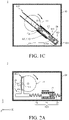
Figs. 1A-1C are schematic diagrams of a co-constructed power generation device according to an embodiment of this disclosure; -
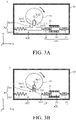
Figs. 2A-2C are schematic diagrams of a co-constructed power generation device according to another embodiment of this disclosure; -
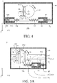
Figs. 3A-3D are schematic diagrams of a co-constructed power generation device according to yet another embodiment of this disclosure; -
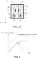
Fig. 4 is a schematic diagram of a co-constructed power generation device according to yet another embodiment of this disclosure; -
Figs. 5A-5B are schematic diagrams of an example of another co-constructed power generation device, which is not part of the invention. -
Fig. 6 is an elastic modulus ratio versus power generation efficiency graph of a co-constructed power generation device according to an embodiment of this disclosure; -
Figs. 7A-7B are schematic diagrams of an example of another co-constructed power generation device, which is not part of the invention. -
Figs. 8A-8B are schematic diagrams of an example of another co-constructed power generation device, which is not part of the invention. and -
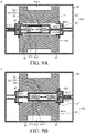
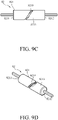
Figs. 9A-9D are schematic diagrams of an example of another co-constructed power generation device, which is not part of the invention. - In the following detailed description, for purposes of explanation, numerous specific details are set forth in order to provide a thorough understanding of the disclosed embodiments. It will be apparent, however, that one or more embodiments may be practiced without these specific details. In other instances, well-known structures and devices are schematically shown in order to simplify the drawings.
- The co-constructed power generation device provided in this disclosure comprises a shell member, wherein electric power is generated by shaking (hereafter called "shake-induced power"), and and electric power is generated by rotating (hereafter called "rotation-induced power"). The co-constructed power generation device provided in this disclosure is applied to various types of devices each of which has a rotary mechanism, and more particularly to a device which has a rotary mechanism and mobility, such as pet leash, bicycle, flywheel, fishing rod and reel, or automatic retractor, but is not limited to these.
- Please refer to
Figs. 1A-1C which are schematic diagrams of a co-constructed power generation device according to an embodiment of this disclosure. As shown inFigs. 1A-1C , the co-constructedpower generation device 1 comprises ashell member 10, a rotatingmember 11 and anelectromagnetic coil 12. The rotatingmember 11, such as a circular disc, is rotatably disposed at theshell member 10. Theelectromagnetic coil 12 is disposed in theshell member 10. In this embodiment, the co-constructedpower generation device 1 comprises a firstmagnetic body 13, a firstelastic member 14 and a secondelastic member 15, with the first and secondelastic members magnetic body 13 and the firstmagnetic body 13 suspended within theelectromagnetic coil 12. The firstmagnetic body 13, the firstelastic member 14 and the secondelastic member 15 generate the shake-induced power from the relative movement between the firstmagnetic body 13 and theelectromagnetic coil 12, with the relative movement resulted from the shake of the firstmagnetic body 13 caused by the external force applied to theshell member 10. In brief, the the shake-induced power is generated. The co-constructedpower generation device 1 further comprises a connectingmember 16 connecting the rotatingmember 11 and theshell member 10. Theelectromagnetic coil 12 is wrapped around the connectingmember 16. When the rotatingmember 11 rotates, the connectingmember 16 brings the firstmagnetic body 13 to move relatively to theelectromagnetic coil 12 so as to generate the rotation-induced power. In brief, the rotation-induced power is generated. - More specifically, the connecting
member 16 comprises atranslation rail 161 and anend part 162, with thetranslation rail 161 extending from theend part 162. For example, thetranslation rail 161 is formed by two sidewalls extending from theend part 162. Thetranslation rail 161 is slidably connected with apivoting pin 111 of the rotatingmember 11, with the pivotingpin 111 fixed on the rotatingmember 11. Theend part 162 of the connectingmember 16 is rotatably connected with a fixedportion 101 of theshell member 10. In this embodiment, the fixedportion 101 comprises an extendingpin 1010 for being fixed on theshell member 10, but the fixedportion 101 of this disclosure is not limited to comprise this member. In another embodiment, the fixedportion 101 does not have the extendingpin 1010 and is directly fixed on theshell member 10. The firstmagnetic body 13, the firstelastic member 14 and the secondelastic member 15 are slidably disposed in thetranslation rail 161. Two ends of the firstmagnetic body 13 are respectively connected with the firstelastic member 14 and the secondelastic member 15. The end, which is not connected with the firstmagnetic body 13, of the firstelastic member 14 is connected with the pivotingpin 111. The end, which is not connected with the firstmagnetic body 13, of the secondelastic member 15 is connected with the fixedportion 101 of theshell member 10. When the rotatingmember 11 rotates, the pivotingpin 111 rotates following the rotatingmember 11 and slides along thetranslation rail 161 to bring the connectingmember 16 to rotate around the fixedportion 101 as a rotary center, so that the firstmagnetic body 13 moves relatively to theelectromagnetic coil 12. In other words, when the rotatingmember 11 rotates, the pivotingpin 111 slides along thetranslation rail 161 following the movement of the rotatingmember 11 to compress or stretch the firstelastic member 14 as well as the secondelastic member 15, so that the firstmagnetic body 13 moves relatively to theelectromagnetic coil 12 which is wrapped around thetranslation rail 161. - Therefore, the shake-induced power can be generated from the relative displacement between the first
magnetic body 13 and theelectromagnetic coil 12 caused by the shake of the firstmagnetic body 13, and the rotation of the rotatingmember 11 is converted into the relative displacement between the firstmagnetic body 13 and theelectromagnetic coil 12 so as to generate the rotation-induced power. The mechanism of the co-constructedpower generation device 1 can perform both of the shake-induced power generation and rotation-induced power generation through the sameelectromagnetic coil 12 andmagnetic body 13.Figs. 1A-1C exemplarily illustrate theelectromagnetic coil 12 wound around the outside of thetranslation rail 161. Moreover, theelectromagnetic coil 12 can also be embedded in thetranslation rail 161 of the connectingmember 16, or be wrapped around thetranslation rail 161 in other form, which is not limited in this disclosure. - For another embodiment, please refer to
Figs. 2A-2C which are schematic diagrams of a co-constructed power generation device according to this embodiment of this disclosure. As shown inFigs. 2A-2C , the co-constructedpower generation device 2 comprises ashell member 20, a rotatingmember 21 and anelectromagnetic coil 22. The rotatingmember 21, such as a circular disc, is rotatably disposed at theshell member 20. Theelectromagnetic coil 22 is fixedly disposed at theshell member 20. In this embodiment, the co-constructedpower generation device 2 comprises a firstmagnetic body 23, a firstelastic member 24 and a secondelastic member 25, with the first and secondelastic members magnetic body 23 and the firstmagnetic body 23 suspended within theelectromagnetic coil 22. The shake-induced power is generated from the relative movement between the firstmagnetic body 23 and theelectromagnetic coil 22, with the relative movement resulted from the shake of the firstmagnetic body 23 caused by the external force applied to theshell member 20. The co-constructedpower generation device 2 further comprises a connectingmember 26 connecting the rotatingmember 21 and the firstelastic member 24. When the rotatingmember 21 rotates, the connectingmember 26 brings the first magneticelectromagnetic coil 12 caused by the shake of the firstmagnetic body 13, and the second power generation group A12 converts the rotation of the rotatingmember 11 into the relative displacement between the firstmagnetic body 13 and theelectromagnetic coil 12 so as to generate the rotation-induced power. The mechanism of the co-constructedpower generation device 1 can perform both of the shake-induced power generation and rotation-induced power generation through the sameelectromagnetic coil 12 andmagnetic body 13.Figs. 1A-1C exemplarily illustrate theelectromagnetic coil 12 wound around the outside of thetranslation rail 161. Moreover, theelectromagnetic coil 12 can also be embedded in thetranslation rail 161 of the connectingmember 16, or be wrapped around thetranslation rail 161 in other form, which is not limited in this disclosure. - For another embodiment, please refer to
Figs. 2A-2C which are schematic diagrams of a co-constructed power generation device according to this embodiment of this disclosure. As shown inFigs. 2A-2C , the co-constructedpower generation device 2 comprises ashell member 20, a rotatingmember 21, anelectromagnetic coil 22, a first power generation group A21 and a second power generation group A22. The rotatingmember 21, such as a circular disc, is rotatably disposed at theshell member 20. Theelectromagnetic coil 22 is fixedly disposed at theshell member 20, and the first power generation group A21 as well as the second power generation group A22 is disposed in theshell member 20. In this embodiment, the first power generation group A21 comprises a firstmagnetic body 23, a firstelastic member 24 and a secondelastic member 25, with the first and secondelastic members magnetic body 23 and the firstmagnetic body 23 suspended within theelectromagnetic coil 22. The first power generation group A21 generates the shake-induced power from the relative movement between the firstmagnetic body 23 and theelectromagnetic coil 22, with the relative movement resulted from the shake of the firstmagnetic body 23 caused by the external force applied to theshell member 20. The second power generation group A22 comprises a connectingmember 26 connecting the rotatingmember 21 and the firstelastic member 24. When the rotatingmember 21 rotates, the connectingmember 26 brings the firstmagnetic body 23 to move relatively to theelectromagnetic coil 22 so as to generate the rotation-induced power. - More specifically, in this embodiment, the connecting
member 26 comprises atranslation rail 261 extending along a first direction (e.g. the direction of y-axis in the figures). Thetranslation rail 261 is slidably connected with apivoting pin 211 of the rotatingmember 21, with the pivoting pin fixed on the rotatingmember 21. As aforementioned, the two ends of the firstmagnetic body 23 are respectively connected with the firstelastic member 24 and the secondelastic member 25. The end, which is not connected with the firstmagnetic body 23, of the firstelastic member 24 is connected with one side of the connectingmember 26; the end, which is not connected with the firstmagnetic body 23, of the secondelastic member 25 is connected with theshell member 20. For example, as shown inFigs. 2A-2C , the connectingmember 26 can be a T-shaped rod member and comprise atranslation rail 261 and anend part 262, wherein thetranslation rail 261 extends along the first direction (the direction of y-axis in the figures) and theend part 262 extends along the second direction (the direction of x-axis in the figures). Theend part 262 sequentially connects the firstelastic member 24, the firstmagnetic body 23, the secondelastic member 25 and theshell member 20 along the second direction. In another example, the connectingmember 26 can also be a rod member in L shape, I shape or other shape, which is not limited in this disclosure. - When the rotating
member 21 rotates relatively to theshell member 20, the pivotingpin 211 rotates with the rotatingmember 21 and slides in thetranslation rail 261 along the first direction to bring the connectingmember 26 moves back and forth along the second direction, so that the firstmagnetic body 23 moves along the second direction relatively to theelectromagnetic coil 22 at theshell member 20. In other words, when the rotatingmember 21 rotates, the pivotingpin 211 brings the connectingmember 26 to compress or stretch the firstelastic member 24 as well as the secondelastic member 25, so that the firstmagnetic body 23 moves relatively to theelectromagnetic coil 22 fixed on theshell member 20. Therefore, the rotation of the rotatingmember 21 is converted into the relative displacement between the firstmagnetic body 23 and theelectromagnetic coil 22 through the connectingmember 26, so that theelectromagnetic coil 22 cuts the magnetic field lines of the firstmagnetic body 23 connectingmember 26, and then the rotation-induced power is generated. As aforementioned, the shake-induced power can be generated from the relative displacement between the firstmagnetic body 23 and theelectromagnetic coil 22, with the relative displacement resulted from the shake of the firstmagnetic body 23. As a result, the mechanism of the co-constructedpower generation device 2 can perform both of the shake-induced power generation and rotation-induced power generation through the sameelectromagnetic coil 22 andmagnetic body 23. In this embodiment, as shown inFigs. 2A-2C , the first direction is the direction of y-axis and the second direction is the direction of x-axis for an exemplary explanation. However, in another embodiment, the first direction and the second direction can intersect with each other to form any angle designed according to actual requirements and not limited in this disclosure. - Please refer to
Figs. 3A-3D which are schematic diagrams of a co-constructed power generation device according to yet another embodiment of this disclosure. In this embodiment, the co-constructedpower generation device 3, similar to the co-constructedpower generation device 2 in the above embodiment, comprises ashell member 30, a rotatingmember 31 and anelectromagnetic coil 32, wherein the relative disposition among these components is similar to that of the co-constructedpower generation device 2 in the above embodiment so it is not repeated. The co-constructedpower generation device 3 comprises a firstmagnetic body 33, a firstelastic member 34 and a secondelastic member 35, with the first and secondelastic members magnetic body 33 and the firstmagnetic body 33 suspended within theelectromagnetic coil 32. The co-constructedpower generation device 3 further comprises a connectingmember 36 connecting the rotatingmember 31 and the firstelastic member 34. The connectingmember 36 comprises arod member 361 and a thirdelastic member 362 wherein two ends of the thirdelastic member 362 are respectively connected with one side of therod member 361 and theshell member 30, and the other side of therod member 361 is connected with an end of the firstelastic member 34, with said end of the first elastic member not connected with the firstmagnetic body 33. Therod member 361 comprises atranslation rail 3611 extending along the first direction. Thetranslation rail 3611 is slidably and detachably connected with apivoting pin 311 of the rotatingmember 31. More specifically, the length of thetranslation rail 3611 is less than the diameter of the rotatingmember 31. Thetranslation rail 3611 comprises anopening 3612 at the end which is near the rotary center of the rotatingmember 31, and avalve 3613 is disposed in the position on thetranslation rail 3611 corresponding to the rotary path of the pivotingpin 311. Thevalve 3613 can rotates around a fixed portion of thetranslation rail 3611 as a rotary center so as to enter the interior space of thetranslation rail 3611. - As shown in
Figs. 3A-3B , the pivotingpin 311 rotates along the rotary path to the outside of thetranslation rail 3611, and then enters the interior space of thetranslation rail 3611 via thevalve 3613 and slides in thetranslation rail 3611 along the first direction (the direction of y-axis in the figures) to bring themagnetic body 33, the firstelastic member 34 and the secondelastic member 35 to move along the second direction (the direction of x-axis in the figures), so that the firstmagnetic body 33 moves relatively to theelectromagnetic coil 32. Afterwards, as shown inFigs. 3C-3D , the pivotingpin 311 leaves the interior space of thetranslation rail 3611 via theopening 3612 at the end of thetranslation rail 3611, and therod member 361 returns to the position relative to the rotatingmember 31 as shown inFig. 3A through the release of the elastic potential of the thirdelastic member 362. In this embodiment, the detachable connection between the pivotingpin 311 and thetranslation rail 3611 may allow the shake of firstmagnetic body 33 not to be limited by the pivotingpin 311 when the pivotingpin 311 is outside of thetranslation rail 3611, so that the co-constructedpower generation device 3 may have better power generation efficiency. In this embodiment, as shown inFigs. 3A-3D , the first direction is the direction of y-axis and the second direction is the direction of x-axis for an exemplary explanation. However, in another embodiment, the first direction and the second direction can intersect with each other to form any angle designed according to actual requirements and not limited in this disclosure. - For yet another embodiment, please refer to
Fig. 4 which is a schematic diagram of a co-constructed power generation device according to this another embodiment of this disclosure. As shown inFig. 4 , the co-constructedpower generation device 4, similar to the co-constructedpower generation device shell member 40, a rotatingmember 41 and anelectromagnetic coil 42, wherein the relative disposition among these components is similar to that of the co-constructedpower generation device power generation device 4 further comprises a secondelectromagnetic coil 42b fixed on theshell member 40. Moreover, besides the firstmagnetic body 43, the firstelastic member 44 and the secondelastic member 45 respectively connected with two ends of the firstmagnetic body 43, the co-constructedpower generation device 4 further comprises a secondmagnetic body 43b, a thirdelastic member 44b and a fourthelastic member 45b. The secondmagnetic body 43b is suspended within the secondelectromagnetic coil 42b. Two ends of the thirdelastic member 44b are respectively connected with the secondmagnetic body 43b and the connectingmember 46 of the second power generation group A42. In other words, the connectingmember 46 is connected with the firstelastic member 44 via one side, and connected with the thirdelastic member 44b via the other side. Two ends of the fourthelastic member 45b are respectively connected with the secondmagnetic body 43b and theshell member 40. - When an external force is applied to the
shell member 40, the firstmagnetic body 43 and the secondmagnetic body 43b are shaken by the external force. As a result, the firstmagnetic body 43 moves relatively to theelectromagnetic coil 42 and the secondmagnetic body 43b moves relatively to the secondelectromagnetic coil 42b so as to generate the electric power. As described in the above embodiments, when the rotatingmember 41 rotates, the connectingmember 46 moves back and forth along the second direction since it is connected with the pivotingpin 411 of the rotatingmember 41. In this embodiment, the connectingmember 46 simultaneously brings the firstmagnetic body 43 to move back and forth relatively to theelectromagnetic coil 42 and the secondmagnetic body 43b to move back and forth relatively to the secondelectromagnetic coil 42b. More specifically, as shown inFig. 4 , the connectingmember 46 moves back and forth along the second direction so as to compress the first and secondelastic member elastic member elastic member elastic member member 46 brings the firstmagnetic body 43 and the secondmagnetic body 43b to move back and forth along the second direction. During this movement of the first and secondmagnetic bodies magnetic body 43 are cut by theelectromagnetic coil 42 fixed on theshell member 40, and the magnetic field lines generated by the secondmagnetic body 43b are cut by the secondelectromagnetic coil 42b fixed on theshell member 40, so as to generate the electric power. - Please refer to
Figs. 5A-5B which are schematic diagrams of a co-constructed power generation device which is not part of the invention, whereinFig. 5A is a front sectional view of the co-constructed power generation device, andFig. 5B is a side sectional view of the co-constructed power generation device. In this embodiment, the co-constructedpower generation device 5 comprises ashell member 50, a rotatingmember 51 and two sets of the first and second power generation groups A51 and A52 as aforementioned. The two sets of the first and second power generation groups A51 and A52 are respectively disposed on the front and the back of the rotatingmember 51, wherein the power generation mechanism of each first power generation group A51 in the two sets is similar to that of the first power generation group described in the above embodiments, and the power generation mechanism of each second power generation group A52 in the two sets is similar to that of the second power generation group described in the above embodiments, so the related details are not repeated. InFigs. 5A-5B , the co-constructedpower generation device 5 is exemplarily illustrated to comprise two sets of the first and second power generation groups A21 and A22 as described in the embodiment ofFigs. 2A-2C ; however, the co-constructedpower generation device 5 can also comprise two sets of the first and second power generation groups as described in the embodiment ofFigs. 1A-1C ,Figs. 3A-3D orFig. 4 , or respectively belonging to two of the embodiments ofFigs. 1A-1C ,Figs. 2A-2C ,Figs. 3A-3D andFig. 4 . InFigs 5A-5B , the rotatingmember 51 is pivoted on theshell member 50 via a rotatingbase 512. Moreover, in each of the above embodiments, the rotating member can also be rotatably disposed in the shell member via a rotating base or other structure. - In the above one or more embodiments, the connecting member bring the first elastic member and the second elastic member to move relatively to each other so as to convert the kinetic energy of the first magnetic body into electric power. If the elastic modulus of the first elastic member is designed to be quite low, the displacement of the connecting member is mostly absorbed by the deformation of the elastic member, so that the displacement of the first magnetic body is less and the power generation efficiency is low. On the contrary, if the elastic modulus of the first elastic member is designed to be quite high, the first elastic member is hard to be deformed, so that the first magnetic body is hard to be shaken by the external force applied to the shell member to generate electric power. For obtaining an appropriate set of elastic moduli, please refer to
Fig. 6 which is an elastic modulus ratio versus power generation efficiency graph of a co-constructed power generation device according to an embodiment of this disclosure. InFig. 6 , the x-axis indicates the ratio of the elastic modulus of the first elastic member to the elastic modulus of the second elastic member, and the y-axis indicates the power generation efficiency of the co-constructed power generation, wherein the power generation efficiency has a positive correlation with the electric power. The formula of the electric power is shown as follows:
- As shown in
Fig. 6 , for the shake-induced power generation, as the elastic modulus K1 of the first elastic member increases, the first elastic member is harder to being shaken by the external force applied to the shell member, so that the shaking power generation efficiency decreases as the elastic modulus K1 of the first elastic member increases. In contrast, for the rotation-induced power generation, as the elastic modulus K1 of the first elastic member increases, the first elastic member is harder to be deformed, so that it is easier to bring the first magnetic body to move as the connecting member moves, and the rotating power generation efficiency increases as the elastic modulus K1 of the first elastic member increases. Therefore, the shaking power generation efficiency curve and the rotating power generation efficiency curve converge with each other at a point O1. More particularly, the elastic modulus ratio corresponding to the point O1 indicates that the elastic modulus of the first elastic member is larger than that of the second elastic member. By disposing the first and second elastic members having the above elastic modulus ratio (corresponding to the point O1) therebetween in the co-constructed power generation device, great power generation efficiency of the co-constructed power generation device in both the shake-induced power generation mode and the rotation-induced power generation mode may be achieved. In the above embodiment, the ratio of the elastic modulus of the third elastic member to that of the fourth elastic member is similar to the ratio of the elastic modulus of the first elastic member to that of the second elastic member as aforementioned, so the related details are not repeated. - The mechanism of the co-constructed power generation device as described in the above one or more embodiments can perform both of shake-induced power generation and rotation-induced power generation through the same set of magnetic body and electromagnetic coil, so that the space conventionally required for disposing the power generation structures respectively corresponding to the two types of power generation may be simplified, and the overall size of the power generation device may be reduced.
- Please refer to
Figs. 7A-7B which are schematic diagrams of a co-constructed power generation device which is not part of the invention. As shown inFigs. 7A-7B , the co-constructedpower generation device 6 comprises ashell member 60, a rotatingmember 61, anelectromagnetic coil 62, a first power generation group A61 generating the shake-induced power, and a second power generation group A62 generating the rotation-induced power, wherein the rotatingmember 61 is rotatably disposed at theshell member 60, theelectromagnetic coil 62 is disposed at the rotatingmember 61, and the first and second power generation groups A61 and A62 are disposed in theshell member 60. The first power generation group A61 comprises a firstmagnetic body 63, a firstelastic member 64 and a secondelastic member 65, wherein the firstmagnetic body 63 is suspended within theelectromagnetic coil 62, and two ends of the firstmagnetic body 63 are respectively connected with the firstelastic member 64 and the secondelastic member 65. - More specifically, a
rod member 66 is disposed at the rotatingmember 61 and has an accommodating space therein. Theelectromagnetic coil 62 is wrapped around this accommodating space, and the first power generation group A61 is disposed in this accommodating space. The first power generation group A61 is connected with therod member 66 via one end of the firstelastic member 64 and one end of the secondelastic member 65 so as to suspend the firstmagnetic body 63 within the accommodating space, wherein said ends of the first andsecond members magnetic body 63. More particularly, it is preferable that the elastic modulus of the firstelastic member 64 is the same as that of the secondelastic member 65, so that the firstmagnetic body 63 may be suspended in the center of the accommodating space and the probability of colliding with the inner wall of therod member 66 by the firstmagnetic body 63 may be reduced. In this embodiment, theelectromagnetic coil 62 is embedded in the sidewall of therod member 66. In another embodiment, theelectromagnetic coil 62 can also be wrapped on the external surface of therod member 66. When an external force is applied to theshell member 60, this external force causes the shake of the firstmagnetic body 63 and the relative movement between the firstmagnetic body 63 and theelectromagnetic coil 62, so that electric power is generated by shaking. The second power generation group A62 comprises a plurality of secondmagnetic bodies 67 disposed at theshell member 60 and surrounding theelectromagnetic coil 62. When the rotatingmember 61 rotates, theelectromagnetic coil 62 disposed at the rotatingmember 61 moves relatively to the secondmagnetic body 67 so that electric power is generated by rotating. - Please refer to
Figs. 8A-8B which are schematic diagrams of a co-constructed power generation device which is not part of the invention. As shown inFigs. 8A-8B , the co-constructedpower generation device 7, similar to the co-constructedpower generation device 6 in the above embodiment, comprises ashell member 70, a rotatingmember 71, anelectromagnetic coil 72, a first power generation group A71 generating the shake-induced power, and a second power generation group A72 generating the rotation-induced power, wherein the rotatingmember 71 is rotatably disposed at theshell member 70. The first power generation group A61 similarly comprises a firstmagnetic body 73, a firstelastic member 74 and a secondelastic member 75, wherein the firstmagnetic body 73 is suspended within theelectromagnetic coil 72, and two ends of the firstmagnetic body 73 are respectively connected with the firstelastic member 74 and the secondelastic member 75. Moreover, the second power generation group A72 similarly comprises a plurality of secondmagnetic bodies 77 surrounding theelectromagnetic coil 72. The difference between this embodiment and the previous embodiment ofFigs. 7A-7B is that theelectromagnetic coil 72 is disposed at theshell member 70 and the secondmagnetic bodies 77 of the second power generation group A72 are disposed at the rotatingmember 71. - More specifically, a
rod member 76 is disposed at theshell member 70 of the co-constructedpower generation device 7. Similar to therod member 66 in the previous embodiment, therod member 76 has an accommodating space for accommodating the first power generation group A71, wherein the accommodating space is surrounded by theelectromagnetic coil 72. In this embodiment, one end of the firstelastic member 74 of the first power generation group A71 and one end of the secondelastic member 75 of the first power generation group A71 are fixedly connected with therod member 76 in its accommodating space, and the other end of the firstelastic member 74 and the other end of the secondelastic member 75 are respectively connected with two ends of the firstmagnetic body 73 so as to suspend the first magnetic body 73in the accommodating space. More particularly, it is preferable that the elastic modulus of the firstelastic member 74 is the same as that of the secondelastic member 75, so that the firstmagnetic body 73 may be suspended in the center of the accommodating space and the probability of colliding with the inner wall of therod member 76 by the firstmagnetic body 73 may be reduced. Theelectromagnetic coil 72 can be embedded in the sidewall of therod member 76, or be wrapped on the external surface of therod member 76. In this embodiment, when the rotatingmember 71 rotates, the secondmagnetic bodies 77 disposed at the rotatingmember 71 rotates and moves relatively to theelectromagnetic coil 72 fixed at theshell member 70 so that electric power is generated. - Please refer to
Figs. 9A-9D which are schematic diagrams of a co-constructed power generation device which is not part of the invention. As shown inFigs. 9A-9D , the co-constructedpower generation device 8 comprises ashell member 80, rotatingmember 81, anelectromagnetic coil group 82, a first power generation group A81 generating the shake-induced power, and a second power generation group A82 generating the rotation-induced power, wherein the rotatingmember 81 is rotatably disposed at theshell member 80. More specifically, theshell member 80 comprises aspindle 801 to be pivoted by the rotatingmember 81. Theelectromagnetic coil group 82 is movably disposed in thespindle 801, and the first power generation group A81 is disposed in theelectromagnetic coil group 82. Theelectromagnetic coil group 82 comprises arod member 821 and anelectromagnetic coil 822, wherein therod member 821 is configured to accommodate the first power generation group A81 and theelectromagnetic coil 822 is wrapped around therod member 821. In this embodiment, theelectromagnetic coil 822 is embedded in the sidewall of therod member 821. - The first power generation group A81 comprises a first magnetic body 83, a first
elastic member 84 and a secondelastic member 85, wherein the first magnetic body 83 is connected with the firstelastic member 84 and the secondelastic member 85 and suspended within theelectromagnetic coil 822. More specifically, therod member 821 comprises afirst end part 8211, asecond end part 8212 and asidewall 8213 which extends from thefirst end part 8211 to thesecond part 8212. Thefirst end part 8211, thesecond end part 8214 and thesidewall 8213 form anaccommodating space 8214 together. Two ends of the first magnetic body 83 are respectively connected with the firstelastic member 84 and the secondelastic member 85. The end, which is not connected with the first magnetic body 83, of the firstelastic member 84 is connected with thefirst end part 8211 of therod member 821, and the end, which is not connected with the first magnetic body 83, of the secondelastic member 85 is connected with thesecond end part 8212, so as to suspend the first magnetic body 83 in theaccommodating space 8214. More particularly, it is preferable that the elastic modulus of the firstelastic member 84 is the same as that of the secondelastic member 85, so that the first magnetic body 83 may be suspended in the center of theaccommodating space 8214 and the probability of colliding with the inner wall of the rod member 86 by the firstmagnetic body 73 may be reduced. The external force applied to theshell member 80 causes the shake of the first magnetic body 83 and the relative movement between the first magnetic body 83 and theelectromagnetic coil 62, so that electric power is generated by shaking. The second power generation group A82 comprises a connectingmember 811 disposed at the rotatingmember 81, and a secondmagnetic assembly 87. More particularly, the secondmagnetic assembly 87 comprises two magnetic bodies respectively disposed at two ends of thespindle 801. When the rotatingmember 81 rotates, the connectingmember 811 brings theelectromagnetic coil group 82 to move relatively to the secondmagnetic assembly 87 so as to generate electric power. - More specifically, the
rod member 821 is slidably connected with theshell member 80 via thefirst end part 8211 and thesecond end part 8212. There is a closed-loop groove 8215 disposed on the external surface of thesidewall 8213 of therod member 821, and this closed-loop groove 8215 is slidably connected with the connectingmember 811. When the rotatingmember 81 rotates, the connectingmember 811 slides along the closed-loop groove 8215 on therod member 821 so as to bring theelectromagnetic coil group 82 to move relatively to the secondmagnetic assembly 87 along the direction in which thespindle 801 extends. More particularly, each of the first andsecond end parts rod member 821 comprises a connecting bar for slidably connected with theshell member 80. The cross-section of the connecting bar is designed to be a polygon in order to avoid the situation that theelectromagnetic coil group 82 is rotated by the friction between the connectingmember 811 and the closed-loop groove 8214 when the rotatingmember 81 rotates. Moreover,Figs. 9C-9D exemplarily illustrate the track of the closed-loop groove 8215; however, the track of the closed-loop groove 8215 in practice can be designed based on requirements. - In the aforementioned embodiments, the electromagnetic coil can be connected with power storage for storing the generated electric power. In each figure of this disclosure, the cross-section of the shell member is exemplarily illustrated as a rectangle; however, the cross-section of the shell member can also be designed to be a circle or other shape based on actual requirements, and is not limited in this disclosure. Moreover, in each of the schematic diagrams corresponding to the above embodiments, the clockwise arrow indicates the rotary direction of the rotating member for the exemplary explanation of the operation mechanism of the co-constructed power generation device, and the co-constructed power generation device also has the similar operation mechanism when the rotating member rotates counterclockwise.
- In view of the above description, the co-constructed power generation device provided in this disclosure performs both of shake-induced power generation and rotation-induced power generation through the same one electromagnetic coil and one or more magnetic bodies, so that the space conventionally required for disposing the power generation structures respectively corresponding to the two types of power generation may be simplified, the overall size of the power generation device may be reduced, and the usage convenience of the power generation device may be improved. Moreover, by the design of the elastic moduli of the elastic members disposed in the co-constructed power generation device of this disclosure, the co-constructed power generation device may have great power generation efficiency in both the shake-induced power generation mode and the rotation-induced power generation mode. In addition, the collision between the magnetic body and the shell member/rod member may be reduced.
Claims (7)
- A co-constructed power generation device (1), comprising:A shell member (10);a rotating member (11), rotatably disposed at the shell member (10);an electromagnetic coil (12), disposed in the shell member (10);a first magnetic body (13) suspended within the electromagnetic coil (12);a first elastic member (14) and a second elastic member (15), with the first elastic member (14) and the second elastic member (15) respectively connected with two ends of the first magnetic body (13) wherein the shake-induced power is generated from a relative movement between the first magnetic body (13) and the electromagnetic coil (12), with the relative movement resulted from a shake of the first magnetic body (13) caused by an external force applied to the shell member (10); and characterised bya connecting member (16), connecting the rotating member (11) and the shell member (10), wherein the electromagnetic coil (12) is wrapped around the connecting member (16), and when the rotating member (11) rotates, the connecting member (16) brings the first magnetic body (13) to move relatively to the electromagnetic coil (12) so as to generate the rotation-induced power.
- The co-constructed power generation device (1) according to claim 1, characterized in that the connecting member (16) comprises an end part (162) and a translation rail, with the translation rail (161) extending from the end part (162) and slidably connected with a pivoting pin (111) of the rotating member (11), and the end part (162) rotatably connected with a fixed portion (101) of the shell member (10), wherein the first magnetic body (13), the first elastic member (14) and the second elastic member (15) are disposed in the translation rail (161), an end of the first elastic member (14) is connected with the pivoting pin (111) and an end of the second elastic member (15) is connected with the fixed portion (101), with said ends of the first elastic member (14) and the second elastic member (15) are ends that are not connected with the first magnetic body (13), wherein when the rotating member (11) rotates, the pivoting pin (111) slides along the translation rail (161) to bring the connecting member (16) to rotate around the fixed portion (101) as a rotary center so that the first magnetic body (13) moves relatively to the electromagnetic coil (12).
- A co-constructed power generation device (2, 3, 4), comprising:a rotating member (21, 31, 41), rotatably disposed at the shell member (20, 30, 40);an electromagnetic coil (22, 32, 42), disposed at the shell member (20, 30, 40);a first magnetic body (23, 33, 43), suspended within the electromagnetic coil (22, 32, 42);a first elastic member (24, 34, 44) and a second elastic member (25, 35, 45), with the first elastic member (24, 34, 44) and the second elastic member (25, 35, 45) respectively connected with two ends of the first magnetic body (23, 33, 43), wherein the shake-induced power is generated from relative movement between the first magnetic body (23, 33, 43) and the electromagnetic coil (22, 32, 42), with the relative movement resulted from a shake of the first magnetic body (23, 33, 43) caused by an external force applied to the shell member (20, 30, 40); and characterised bya connecting member (26, 36, 46) connecting the rotating member (21, 31, 41) and the first elastic member (24, 34, 44), wherein when the rotating member (21, 31, 41) rotates, the connecting member (26, 36, 46) brings the first magnetic body (23, 33, 43) to move relatively to the electromagnetic coil (22, 32, 42) so as to generate the rotation-induced power.
- The co-constructed power generation device (2, 4) according to claim 3, characterized in that the connecting member (26, 46) comprises a translation rail (261, 461) extending in a first direction and slidably connected with a pivoting pin (211, 411) of the rotating member (21, 41), an end of the first elastic member (24, 44) is connected with a side of the connecting member (26, 46) and an end of the second elastic member (25, 45) is connected with the shell member (20, 40), with said ends of the first elastic member (24, 44) and the second elastic member (25, 45) are ends that are not connected with the first magnetic body (23, 43), wherein when the rotating member (21, 41) rotates, the pivoting pin (211, 411) slides along the translation rail (261, 461) to bring the connecting member (26, 46) to move along a second direction so that the first magnetic body (23, 43) moves along the second direction relatively to the electromagnetic coil (22, 42), with the second direction intersecting with the first direction.
- The co-constructed power generation device (3) according to claim 3, characterized in that the connecting member (36) comprises a rod member (361) and a third elastic member (362), an end of the first elastic member (34) is connected with a side of the rod member (361) and an end of the second elastic member (35) is connected with the shell member (30), with said ends of the first elastic member (34) and the second elastic member (35) are ends that are not connected with the first magnetic body (33), with two ends of the third elastic member (362) respectively connected with another side of the rod member (361) and the shell member (30), wherein the rod member (361) comprises a translation rail (3611) extending in a first direction, slidably connected with a pivoting pin (311) of the rotating member (31), and comprising an opening (3612) at an end thereof, with a valve (3613) disposed in a position on the translation rail (3611) corresponding to a rotary path of the pivoting pin (311), and the valve (3613) rotating around a fixed portion of the translation rail as a rotary center so as to enter an interior space of the translation rail (3611), wherein when the rotating member (31) rotates, the pivoting pin (311) enters the interior space of the translation rail (3611) through the valve (3613) to slide along the translation rail (3611) to bring the connecting member (36) to move along a second direction, so that the first magnetic body (33) moves along the second direction relatively to the electromagnetic coil (32), with the second direction intersecting with the first direction.
- The co-constructed power generation device (4) according to claim 4 or 5, characterized by further comprising a second electromagnetic coil (42b), a second magnetic body (43b), a third elastic member (44b) and a fourth elastic member (45b), with the third elastic member (44b) and the fourth elastic member (45b) respectively connected with two ends of the second magnetic body (43b), and the second magnetic body (43b) suspended within the second electromagnetic coil (42b), wherein the shake-induced power is further generated from relative movement between the second magnetic body (43b) and the second electromagnetic coil (42b), with the relative movement resulted from a shake of the second magnetic body (43b) caused by the external force applied to the shell member (40), wherein an end of the third elastic member (44b) is connected with another side of the connecting member (46) and an end of the fourth elastic member (45b) is connected with the shell member (40), with said ends of the third elastic member (44b) and the fourth elastic members (45b) are ends that are not connected with the second magnetic body (43b), wherein when the rotating member (41) rotates, the connecting member (46) further brings the second magnetic body (43b) to move along the second direction relatively to the second electromagnetic coil (42b).
- The co-constructed power generation device (1, 2, 3, 4) according to claim 2, 4 or 5, characterized in that an elastic modulus of the first elastic member (14, 24, 34, 44) is larger than an elastic modulus of the second elastic member (15, 25, 35, 45).
Applications Claiming Priority (1)
| Application Number | Priority Date | Filing Date | Title |
|---|---|---|---|
| TW106143768A TWI671977B (en) | 2017-12-13 | 2017-12-13 | Co-constructed power generation device |
Publications (2)
| Publication Number | Publication Date |
|---|---|
| EP3499032A1 EP3499032A1 (en) | 2019-06-19 |
| EP3499032B1 true EP3499032B1 (en) | 2022-03-30 |
Family
ID=61386704
Family Applications (1)
| Application Number | Title | Priority Date | Filing Date |
|---|---|---|---|
| EP18158149.7A Active EP3499032B1 (en) | 2017-12-13 | 2018-02-22 | Co-constructed power generation device |
Country Status (4)
| Country | Link |
|---|---|
| US (1) | US10601292B2 (en) |
| EP (1) | EP3499032B1 (en) |
| CN (1) | CN109921596B (en) |
| TW (1) | TWI671977B (en) |
Families Citing this family (7)
| Publication number | Priority date | Publication date | Assignee | Title |
|---|---|---|---|---|
| TWI671977B (en) * | 2017-12-13 | 2019-09-11 | 緯創資通股份有限公司 | Co-constructed power generation device |
| IT201900003099A1 (en) * | 2019-03-04 | 2020-09-04 | St Microelectronics Srl | ENERGY COLLECTOR AND CORRESPONDING DEVICE |
| JP7333014B2 (en) * | 2019-10-11 | 2023-08-24 | Toto株式会社 | paper roll |
| JP7325718B2 (en) * | 2019-10-11 | 2023-08-15 | Toto株式会社 | paper roll |
| CN111416545B (en) * | 2020-03-31 | 2021-04-16 | 北京纳米能源与系统研究所 | Mechanical Compression Controlled Triboelectric Nanogenerator |
| IT202100012986A1 (en) * | 2021-05-19 | 2022-11-19 | Andrea Ferrerio | Polyphase motor/alternator device with a decrease or cancellation of back EMFs |
| TWI845419B (en) * | 2023-09-26 | 2024-06-11 | 崑山科技大學 | Rolling power-generation massage apparatus |
Family Cites Families (19)
| Publication number | Priority date | Publication date | Assignee | Title |
|---|---|---|---|---|
| US5975714A (en) | 1997-06-03 | 1999-11-02 | Applied Innovative Technologies, Incorporated | Renewable energy flashlight |
| DE20310137U1 (en) | 2003-07-01 | 2004-11-11 | Flexi-Bogdahn Technik Gmbh & Co. Kg | Leash device for a rope that can be rolled up and unrolled to guide animals |
| US20060208579A1 (en) * | 2005-03-18 | 2006-09-21 | Zih Corp. | Parasitic power collection system for portable printer |
| WO2007121382A2 (en) * | 2006-04-14 | 2007-10-25 | Ciiis, Llc | Power generator having a plurality of arranged power generator units |
| US7538445B2 (en) | 2006-05-05 | 2009-05-26 | Sri International | Wave powered generation |
| US7482717B2 (en) * | 2006-06-15 | 2009-01-27 | Hochhalter Keith W | Servo actuator with self positioning rotor and method |
| US20120139262A1 (en) * | 2006-10-05 | 2012-06-07 | Marshall University Research Corporation | Motion induced electric generator |
| US20080296984A1 (en) * | 2007-05-29 | 2008-12-04 | Sanyo Electric Co., Ltd. | Energy converter |
| JP5193545B2 (en) * | 2007-09-27 | 2013-05-08 | 三洋電機株式会社 | Power generation device and electronic device |
| US8807258B2 (en) * | 2008-03-11 | 2014-08-19 | Physics Lab Of Lake Havasu, Llc | Regenerative suspension with accumulator systems and methods |
| TWM356802U (en) * | 2008-10-14 | 2009-05-11 | ren-hao Dai | Pedal-type electricity generator |
| WO2011026514A1 (en) * | 2009-09-02 | 2011-03-10 | Siemens Aktiengesellschaft | Device for generating electrical energy from mechanical vibrations and associated method |
| JP5764929B2 (en) * | 2010-04-14 | 2015-08-19 | 株式会社安川電機 | Linear rotary actuator |
| JP4692688B1 (en) * | 2010-07-28 | 2011-06-01 | 株式会社安川電機 | Rotating electric machines, direct acting electric machines, and wind power generation systems |
| CA2806877A1 (en) * | 2010-07-29 | 2012-02-02 | Lei ZUO | Electricity generating shock absorbers |
| JP6202349B2 (en) * | 2013-03-07 | 2017-09-27 | 北海道特殊飼料株式会社 | Power generator |
| EP3059850A4 (en) * | 2013-10-14 | 2017-06-07 | Sunrising Eco-Friendly Tech. Co., Ltd. | Mobile induction and power-generation device |
| CN205792025U (en) * | 2016-07-05 | 2016-12-07 | 河北工业大学 | A kind of straight line adds rotary generator formula Wave power generation device |
| TWI671977B (en) * | 2017-12-13 | 2019-09-11 | 緯創資通股份有限公司 | Co-constructed power generation device |
-
2017
- 2017-12-13 TW TW106143768A patent/TWI671977B/en active
- 2017-12-27 CN CN201711444365.3A patent/CN109921596B/en active Active
-
2018
- 2018-02-21 US US15/901,586 patent/US10601292B2/en active Active
- 2018-02-22 EP EP18158149.7A patent/EP3499032B1/en active Active
Also Published As
| Publication number | Publication date |
|---|---|
| EP3499032A1 (en) | 2019-06-19 |
| TW201929394A (en) | 2019-07-16 |
| TWI671977B (en) | 2019-09-11 |
| US20190181738A1 (en) | 2019-06-13 |
| US10601292B2 (en) | 2020-03-24 |
| CN109921596A (en) | 2019-06-21 |
| CN109921596B (en) | 2020-03-31 |
Similar Documents
| Publication | Publication Date | Title |
|---|---|---|
| EP3499032A1 (en) | Co-constructed power generation device | |
| US10544781B2 (en) | Elastic energy storage and deployment system | |
| US4499341A (en) | Extensible electrical cable assembly | |
| KR101766770B1 (en) | Active clutch mechanism and jumping robot having the same | |
| KR102409249B1 (en) | An assembly to control or govern relative speed of movement between parts | |
| US20160164389A1 (en) | Electric motor combined with power generator using coil plate having separate coil bodies and reciprocating magnet plate having separate magnets | |
| EP1862409A1 (en) | Gravity type wheel conveyor or roller conveyor capable of controllably braking carried object | |
| CN209881677U (en) | Electric energy collector device | |
| CA2864205C (en) | Motion-damping systems and methods including the same | |
| JP2010283983A (en) | Generation device | |
| WO2017004511A2 (en) | Bi-directionally acting differential drive apparatuses, systems, and methods | |
| CN102162510B (en) | Actuator | |
| KR101792512B1 (en) | Battery To Be Charged Wireless | |
| CN113336019B (en) | Reciprocating wire arrangement device | |
| KR101705576B1 (en) | Rotating power increasing device for motor | |
| KR101357817B1 (en) | Passive Brake Apparatus for Cable Driving Apparatus | |
| WO2024005882A1 (en) | Moving magnet tilt actuator | |
| US11606007B2 (en) | Motor and electric vehicle including the same | |
| JP2013066986A (en) | Attachment structure of cable protection guide member and robot having the attachment structure | |
| US9059608B2 (en) | Rotation assistance device, rotation assistance method, and power generation device | |
| CN223188713U (en) | A telescopic wire device | |
| US20250247023A1 (en) | Electromagnetic Kinetic Energy Harvester | |
| JP5908299B2 (en) | Spiral spring device | |
| US20130285780A1 (en) | Magnetic drive | |
| CN109573001A (en) | Fluid drive apparatus |
Legal Events
| Date | Code | Title | Description |
|---|---|---|---|
| PUAI | Public reference made under article 153(3) epc to a published international application that has entered the european phase |
Free format text: ORIGINAL CODE: 0009012 |
|
| STAA | Information on the status of an ep patent application or granted ep patent |
Free format text: STATUS: REQUEST FOR EXAMINATION WAS MADE |
|
| 17P | Request for examination filed |
Effective date: 20180222 |
|
| AK | Designated contracting states |
Kind code of ref document: A1 Designated state(s): AL AT BE BG CH CY CZ DE DK EE ES FI FR GB GR HR HU IE IS IT LI LT LU LV MC MK MT NL NO PL PT RO RS SE SI SK SM TR |
|
| AX | Request for extension of the european patent |
Extension state: BA ME |
|
| RIC1 | Information provided on ipc code assigned before grant |
Ipc: H02K 7/18 20060101ALI20210826BHEP Ipc: H02K 7/06 20060101ALI20210826BHEP Ipc: H02K 35/02 20060101ALI20210826BHEP Ipc: F03G 7/08 20060101AFI20210826BHEP |
|
| GRAP | Despatch of communication of intention to grant a patent |
Free format text: ORIGINAL CODE: EPIDOSNIGR1 |
|
| STAA | Information on the status of an ep patent application or granted ep patent |
Free format text: STATUS: GRANT OF PATENT IS INTENDED |
|
| GRAJ | Information related to disapproval of communication of intention to grant by the applicant or resumption of examination proceedings by the epo deleted |
Free format text: ORIGINAL CODE: EPIDOSDIGR1 |
|
| GRAP | Despatch of communication of intention to grant a patent |
Free format text: ORIGINAL CODE: EPIDOSNIGR1 |
|
| INTG | Intention to grant announced |
Effective date: 20211011 |
|
| INTG | Intention to grant announced |
Effective date: 20211027 |
|
| GRAS | Grant fee paid |
Free format text: ORIGINAL CODE: EPIDOSNIGR3 |
|
| GRAA | (expected) grant |
Free format text: ORIGINAL CODE: 0009210 |
|
| STAA | Information on the status of an ep patent application or granted ep patent |
Free format text: STATUS: THE PATENT HAS BEEN GRANTED |
|
| AK | Designated contracting states |
Kind code of ref document: B1 Designated state(s): AL AT BE BG CH CY CZ DE DK EE ES FI FR GB GR HR HU IE IS IT LI LT LU LV MC MK MT NL NO PL PT RO RS SE SI SK SM TR |
|
| REG | Reference to a national code |
Ref country code: GB Ref legal event code: FG4D |
|
| REG | Reference to a national code |
Ref country code: CH Ref legal event code: EP |
|
| REG | Reference to a national code |
Ref country code: AT Ref legal event code: REF Ref document number: 1479419 Country of ref document: AT Kind code of ref document: T Effective date: 20220415 |
|
| REG | Reference to a national code |
Ref country code: DE Ref legal event code: R096 Ref document number: 602018032824 Country of ref document: DE |
|
| REG | Reference to a national code |
Ref country code: IE Ref legal event code: FG4D |
|
| REG | Reference to a national code |
Ref country code: LT Ref legal event code: MG9D |
|
| PG25 | Lapsed in a contracting state [announced via postgrant information from national office to epo] |
Ref country code: SE Free format text: LAPSE BECAUSE OF FAILURE TO SUBMIT A TRANSLATION OF THE DESCRIPTION OR TO PAY THE FEE WITHIN THE PRESCRIBED TIME-LIMIT Effective date: 20220330 Ref country code: RS Free format text: LAPSE BECAUSE OF FAILURE TO SUBMIT A TRANSLATION OF THE DESCRIPTION OR TO PAY THE FEE WITHIN THE PRESCRIBED TIME-LIMIT Effective date: 20220330 Ref country code: NO Free format text: LAPSE BECAUSE OF FAILURE TO SUBMIT A TRANSLATION OF THE DESCRIPTION OR TO PAY THE FEE WITHIN THE PRESCRIBED TIME-LIMIT Effective date: 20220630 Ref country code: LT Free format text: LAPSE BECAUSE OF FAILURE TO SUBMIT A TRANSLATION OF THE DESCRIPTION OR TO PAY THE FEE WITHIN THE PRESCRIBED TIME-LIMIT Effective date: 20220330 Ref country code: HR Free format text: LAPSE BECAUSE OF FAILURE TO SUBMIT A TRANSLATION OF THE DESCRIPTION OR TO PAY THE FEE WITHIN THE PRESCRIBED TIME-LIMIT Effective date: 20220330 Ref country code: BG Free format text: LAPSE BECAUSE OF FAILURE TO SUBMIT A TRANSLATION OF THE DESCRIPTION OR TO PAY THE FEE WITHIN THE PRESCRIBED TIME-LIMIT Effective date: 20220630 |
|
| REG | Reference to a national code |
Ref country code: NL Ref legal event code: MP Effective date: 20220330 |
|
| REG | Reference to a national code |
Ref country code: AT Ref legal event code: MK05 Ref document number: 1479419 Country of ref document: AT Kind code of ref document: T Effective date: 20220330 |
|
| PG25 | Lapsed in a contracting state [announced via postgrant information from national office to epo] |
Ref country code: LV Free format text: LAPSE BECAUSE OF FAILURE TO SUBMIT A TRANSLATION OF THE DESCRIPTION OR TO PAY THE FEE WITHIN THE PRESCRIBED TIME-LIMIT Effective date: 20220330 Ref country code: GR Free format text: LAPSE BECAUSE OF FAILURE TO SUBMIT A TRANSLATION OF THE DESCRIPTION OR TO PAY THE FEE WITHIN THE PRESCRIBED TIME-LIMIT Effective date: 20220701 Ref country code: FI Free format text: LAPSE BECAUSE OF FAILURE TO SUBMIT A TRANSLATION OF THE DESCRIPTION OR TO PAY THE FEE WITHIN THE PRESCRIBED TIME-LIMIT Effective date: 20220330 |
|
| PG25 | Lapsed in a contracting state [announced via postgrant information from national office to epo] |
Ref country code: NL Free format text: LAPSE BECAUSE OF FAILURE TO SUBMIT A TRANSLATION OF THE DESCRIPTION OR TO PAY THE FEE WITHIN THE PRESCRIBED TIME-LIMIT Effective date: 20220330 |
|
| PG25 | Lapsed in a contracting state [announced via postgrant information from national office to epo] |
Ref country code: SM Free format text: LAPSE BECAUSE OF FAILURE TO SUBMIT A TRANSLATION OF THE DESCRIPTION OR TO PAY THE FEE WITHIN THE PRESCRIBED TIME-LIMIT Effective date: 20220330 Ref country code: SK Free format text: LAPSE BECAUSE OF FAILURE TO SUBMIT A TRANSLATION OF THE DESCRIPTION OR TO PAY THE FEE WITHIN THE PRESCRIBED TIME-LIMIT Effective date: 20220330 Ref country code: RO Free format text: LAPSE BECAUSE OF FAILURE TO SUBMIT A TRANSLATION OF THE DESCRIPTION OR TO PAY THE FEE WITHIN THE PRESCRIBED TIME-LIMIT Effective date: 20220330 Ref country code: PT Free format text: LAPSE BECAUSE OF FAILURE TO SUBMIT A TRANSLATION OF THE DESCRIPTION OR TO PAY THE FEE WITHIN THE PRESCRIBED TIME-LIMIT Effective date: 20220801 Ref country code: ES Free format text: LAPSE BECAUSE OF FAILURE TO SUBMIT A TRANSLATION OF THE DESCRIPTION OR TO PAY THE FEE WITHIN THE PRESCRIBED TIME-LIMIT Effective date: 20220330 Ref country code: EE Free format text: LAPSE BECAUSE OF FAILURE TO SUBMIT A TRANSLATION OF THE DESCRIPTION OR TO PAY THE FEE WITHIN THE PRESCRIBED TIME-LIMIT Effective date: 20220330 Ref country code: CZ Free format text: LAPSE BECAUSE OF FAILURE TO SUBMIT A TRANSLATION OF THE DESCRIPTION OR TO PAY THE FEE WITHIN THE PRESCRIBED TIME-LIMIT Effective date: 20220330 Ref country code: AT Free format text: LAPSE BECAUSE OF FAILURE TO SUBMIT A TRANSLATION OF THE DESCRIPTION OR TO PAY THE FEE WITHIN THE PRESCRIBED TIME-LIMIT Effective date: 20220330 |
|
| PG25 | Lapsed in a contracting state [announced via postgrant information from national office to epo] |
Ref country code: PL Free format text: LAPSE BECAUSE OF FAILURE TO SUBMIT A TRANSLATION OF THE DESCRIPTION OR TO PAY THE FEE WITHIN THE PRESCRIBED TIME-LIMIT Effective date: 20220330 Ref country code: IS Free format text: LAPSE BECAUSE OF FAILURE TO SUBMIT A TRANSLATION OF THE DESCRIPTION OR TO PAY THE FEE WITHIN THE PRESCRIBED TIME-LIMIT Effective date: 20220730 Ref country code: AL Free format text: LAPSE BECAUSE OF FAILURE TO SUBMIT A TRANSLATION OF THE DESCRIPTION OR TO PAY THE FEE WITHIN THE PRESCRIBED TIME-LIMIT Effective date: 20220330 |
|
| REG | Reference to a national code |
Ref country code: DE Ref legal event code: R097 Ref document number: 602018032824 Country of ref document: DE |
|
| PG25 | Lapsed in a contracting state [announced via postgrant information from national office to epo] |
Ref country code: DK Free format text: LAPSE BECAUSE OF FAILURE TO SUBMIT A TRANSLATION OF THE DESCRIPTION OR TO PAY THE FEE WITHIN THE PRESCRIBED TIME-LIMIT Effective date: 20220330 |
|
| PLBE | No opposition filed within time limit |
Free format text: ORIGINAL CODE: 0009261 |
|
| STAA | Information on the status of an ep patent application or granted ep patent |
Free format text: STATUS: NO OPPOSITION FILED WITHIN TIME LIMIT |
|
| 26N | No opposition filed |
Effective date: 20230103 |
|
| PG25 | Lapsed in a contracting state [announced via postgrant information from national office to epo] |
Ref country code: SI Free format text: LAPSE BECAUSE OF FAILURE TO SUBMIT A TRANSLATION OF THE DESCRIPTION OR TO PAY THE FEE WITHIN THE PRESCRIBED TIME-LIMIT Effective date: 20220330 |
|
| P01 | Opt-out of the competence of the unified patent court (upc) registered |
Effective date: 20230601 |
|
| PG25 | Lapsed in a contracting state [announced via postgrant information from national office to epo] |
Ref country code: IT Free format text: LAPSE BECAUSE OF FAILURE TO SUBMIT A TRANSLATION OF THE DESCRIPTION OR TO PAY THE FEE WITHIN THE PRESCRIBED TIME-LIMIT Effective date: 20220330 |
|
| PG25 | Lapsed in a contracting state [announced via postgrant information from national office to epo] |
Ref country code: MC Free format text: LAPSE BECAUSE OF FAILURE TO SUBMIT A TRANSLATION OF THE DESCRIPTION OR TO PAY THE FEE WITHIN THE PRESCRIBED TIME-LIMIT Effective date: 20220330 |
|
| REG | Reference to a national code |
Ref country code: CH Ref legal event code: PL |
|
| REG | Reference to a national code |
Ref country code: BE Ref legal event code: MM Effective date: 20230228 |
|
| PG25 | Lapsed in a contracting state [announced via postgrant information from national office to epo] |
Ref country code: LU Free format text: LAPSE BECAUSE OF NON-PAYMENT OF DUE FEES Effective date: 20230222 Ref country code: LI Free format text: LAPSE BECAUSE OF NON-PAYMENT OF DUE FEES Effective date: 20230228 Ref country code: CH Free format text: LAPSE BECAUSE OF NON-PAYMENT OF DUE FEES Effective date: 20230228 |
|
| REG | Reference to a national code |
Ref country code: IE Ref legal event code: MM4A |
|
| PG25 | Lapsed in a contracting state [announced via postgrant information from national office to epo] |
Ref country code: IE Free format text: LAPSE BECAUSE OF NON-PAYMENT OF DUE FEES Effective date: 20230222 |
|
| PG25 | Lapsed in a contracting state [announced via postgrant information from national office to epo] |
Ref country code: BE Free format text: LAPSE BECAUSE OF NON-PAYMENT OF DUE FEES Effective date: 20230228 |
|
| PG25 | Lapsed in a contracting state [announced via postgrant information from national office to epo] |
Ref country code: CY Free format text: LAPSE BECAUSE OF FAILURE TO SUBMIT A TRANSLATION OF THE DESCRIPTION OR TO PAY THE FEE WITHIN THE PRESCRIBED TIME-LIMIT; INVALID AB INITIO Effective date: 20180222 |
|
| PG25 | Lapsed in a contracting state [announced via postgrant information from national office to epo] |
Ref country code: HU Free format text: LAPSE BECAUSE OF FAILURE TO SUBMIT A TRANSLATION OF THE DESCRIPTION OR TO PAY THE FEE WITHIN THE PRESCRIBED TIME-LIMIT; INVALID AB INITIO Effective date: 20180222 |
|
| PG25 | Lapsed in a contracting state [announced via postgrant information from national office to epo] |
Ref country code: TR Free format text: LAPSE BECAUSE OF FAILURE TO SUBMIT A TRANSLATION OF THE DESCRIPTION OR TO PAY THE FEE WITHIN THE PRESCRIBED TIME-LIMIT Effective date: 20220330 |
|
| PGFP | Annual fee paid to national office [announced via postgrant information from national office to epo] |
Ref country code: GB Payment date: 20260115 Year of fee payment: 9 |
|
| PGFP | Annual fee paid to national office [announced via postgrant information from national office to epo] |
Ref country code: DE Payment date: 20260115 Year of fee payment: 9 |
|
| PGFP | Annual fee paid to national office [announced via postgrant information from national office to epo] |
Ref country code: FR Payment date: 20260115 Year of fee payment: 9 |