EP3499028A1 - Tool for transporting a windturbine power train subset - Google Patents
Tool for transporting a windturbine power train subset Download PDFInfo
- Publication number
- EP3499028A1 EP3499028A1 EP18382813.6A EP18382813A EP3499028A1 EP 3499028 A1 EP3499028 A1 EP 3499028A1 EP 18382813 A EP18382813 A EP 18382813A EP 3499028 A1 EP3499028 A1 EP 3499028A1
- Authority
- EP
- European Patent Office
- Prior art keywords
- support
- tool
- power train
- transporting
- windturbine
- Prior art date
- Legal status (The legal status is an assumption and is not a legal conclusion. Google has not performed a legal analysis and makes no representation as to the accuracy of the status listed.)
- Granted
Links
Images




Classifications
-
- F—MECHANICAL ENGINEERING; LIGHTING; HEATING; WEAPONS; BLASTING
- F03—MACHINES OR ENGINES FOR LIQUIDS; WIND, SPRING, OR WEIGHT MOTORS; PRODUCING MECHANICAL POWER OR A REACTIVE PROPULSIVE THRUST, NOT OTHERWISE PROVIDED FOR
- F03D—WIND MOTORS
- F03D13/00—Assembly, mounting or commissioning of wind motors; Arrangements specially adapted for transporting wind motor components
- F03D13/40—Arrangements or methods specially adapted for transporting wind motor components
-
- F—MECHANICAL ENGINEERING; LIGHTING; HEATING; WEAPONS; BLASTING
- F16—ENGINEERING ELEMENTS AND UNITS; GENERAL MEASURES FOR PRODUCING AND MAINTAINING EFFECTIVE FUNCTIONING OF MACHINES OR INSTALLATIONS; THERMAL INSULATION IN GENERAL
- F16M—FRAMES, CASINGS OR BEDS OF ENGINES, MACHINES OR APPARATUS, NOT SPECIFIC TO ENGINES, MACHINES OR APPARATUS PROVIDED FOR ELSEWHERE; STANDS; SUPPORTS
- F16M11/00—Stands or trestles as supports for apparatus or articles placed thereon ; Stands for scientific apparatus such as gravitational force meters
- F16M11/20—Undercarriages with or without wheels
- F16M11/22—Undercarriages with or without wheels with approximately constant height, e.g. with constant length of column or of legs
-
- F—MECHANICAL ENGINEERING; LIGHTING; HEATING; WEAPONS; BLASTING
- F01—MACHINES OR ENGINES IN GENERAL; ENGINE PLANTS IN GENERAL; STEAM ENGINES
- F01D—NON-POSITIVE DISPLACEMENT MACHINES OR ENGINES, e.g. STEAM TURBINES
- F01D25/00—Component parts, details, or accessories, not provided for in, or of interest apart from, other groups
- F01D25/28—Supporting or mounting arrangements, e.g. for turbine casing
-
- F—MECHANICAL ENGINEERING; LIGHTING; HEATING; WEAPONS; BLASTING
- F05—INDEXING SCHEMES RELATING TO ENGINES OR PUMPS IN VARIOUS SUBCLASSES OF CLASSES F01-F04
- F05B—INDEXING SCHEME RELATING TO WIND, SPRING, WEIGHT, INERTIA OR LIKE MOTORS, TO MACHINES OR ENGINES FOR LIQUIDS COVERED BY SUBCLASSES F03B, F03D AND F03G
- F05B2240/00—Components
- F05B2240/50—Bearings
-
- F—MECHANICAL ENGINEERING; LIGHTING; HEATING; WEAPONS; BLASTING
- F05—INDEXING SCHEMES RELATING TO ENGINES OR PUMPS IN VARIOUS SUBCLASSES OF CLASSES F01-F04
- F05B—INDEXING SCHEME RELATING TO WIND, SPRING, WEIGHT, INERTIA OR LIKE MOTORS, TO MACHINES OR ENGINES FOR LIQUIDS COVERED BY SUBCLASSES F03B, F03D AND F03G
- F05B2240/00—Components
- F05B2240/60—Shafts
-
- F—MECHANICAL ENGINEERING; LIGHTING; HEATING; WEAPONS; BLASTING
- F05—INDEXING SCHEMES RELATING TO ENGINES OR PUMPS IN VARIOUS SUBCLASSES OF CLASSES F01-F04
- F05B—INDEXING SCHEME RELATING TO WIND, SPRING, WEIGHT, INERTIA OR LIKE MOTORS, TO MACHINES OR ENGINES FOR LIQUIDS COVERED BY SUBCLASSES F03B, F03D AND F03G
- F05B2260/00—Function
- F05B2260/02—Transport, e.g. specific adaptations or devices for conveyance
-
- F—MECHANICAL ENGINEERING; LIGHTING; HEATING; WEAPONS; BLASTING
- F16—ENGINEERING ELEMENTS AND UNITS; GENERAL MEASURES FOR PRODUCING AND MAINTAINING EFFECTIVE FUNCTIONING OF MACHINES OR INSTALLATIONS; THERMAL INSULATION IN GENERAL
- F16M—FRAMES, CASINGS OR BEDS OF ENGINES, MACHINES OR APPARATUS, NOT SPECIFIC TO ENGINES, MACHINES OR APPARATUS PROVIDED FOR ELSEWHERE; STANDS; SUPPORTS
- F16M7/00—Details of attaching or adjusting engine beds, frames, or supporting-legs on foundation or base; Attaching non-moving engine parts, e.g. cylinder blocks
-
- Y—GENERAL TAGGING OF NEW TECHNOLOGICAL DEVELOPMENTS; GENERAL TAGGING OF CROSS-SECTIONAL TECHNOLOGIES SPANNING OVER SEVERAL SECTIONS OF THE IPC; TECHNICAL SUBJECTS COVERED BY FORMER USPC CROSS-REFERENCE ART COLLECTIONS [XRACs] AND DIGESTS
- Y02—TECHNOLOGIES OR APPLICATIONS FOR MITIGATION OR ADAPTATION AGAINST CLIMATE CHANGE
- Y02E—REDUCTION OF GREENHOUSE GAS [GHG] EMISSIONS, RELATED TO ENERGY GENERATION, TRANSMISSION OR DISTRIBUTION
- Y02E10/00—Energy generation through renewable energy sources
- Y02E10/70—Wind energy
- Y02E10/72—Wind turbines with rotation axis in wind direction
Definitions
- the present invention can be included in the transport sector. Likewise, the present invention can be included in the field of renewable energy, in particular wind energy. More specifically, the object of the invention relates to a tool that is especially designed for transporting a windturbine power train subset, in particular for transporting what is called the low-speed shaft, along with the low-speed shaft bearings and the bearing supports.
- the power train is an assembly of the heaviest subsystem of the nacelle of a wind turbine, given that it includes the following elements: the low-speed shaft (LSS), low-speed shaft bearings (not shown), bearing supports and in certain cases a gearbox is included.
- LSS low-speed shaft
- bearings not shown
- gearbox in certain cases a gearbox is included.
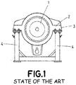
- Figure 1 representing the state of the art, shows the low-speed shaft (1), which is a monolithic rotating piece in the form of a trumpet, and which has sections with decreasing cross sections and sections with uniform cross sections that are generally, but not necessarily, alternating.
- Low-speed bearings (not shown) are respectively mounted on two of said cross sections of different dimensions, which comprise a first bearing and a second bearing, the first bearing being supported on a cross section closer to a first end, with a greater cross section, of the low-speed shaft (1).
- each bearing is supported on the low-speed shaft (1) by a corresponding support (2, 3), in other words, by a first support (2) and a second support (3), respectively, wherein each support (2, 3), when mounted on the low-speed shaft (1), has a longitudinal direction that is perpendicular to the axis of revolution of the low-speed shaft (1).
- the two supports (2, 3) have the same size and therefore have the same length throughout the longitudinal direction thereof, but they could also have different sizes.
- each support (4) supports one end, according to the longitudinal direction, of the corresponding support (2, 3) thereof.
- the present invention describes a tool for transporting a windturbine power train subset, wherein the power train subset comprises: a shaft called "low-speed shaft", at least a first bearing, mounted on the low-speed shaft, and at least a first support for supporting the first bearing on said low-speed shaft, said first support being provided with a first arm and a second arm.
- the power train subset comprises: a shaft called "low-speed shaft", at least a first bearing, mounted on the low-speed shaft, and at least a first support for supporting the first bearing on said low-speed shaft, said first support being provided with a first arm and a second arm.
- the tool of the invention comprises a first support element, which comprises a first resting surface for allowing the first support element to rest on the floor, and at least a first and second support surface, configured to support each one of the respective first arm and second arm of the first support.
- first distance between the first support surface and the first resting surface, as well as a second distance between the second support surface and said first resting surface, wherein the first distance is different from the second distance.
- the power train subset additionally comprises a second bearing, mounted on the low-speed shaft, and a second support, for fastening the second bearing to the low-speed shaft, wherein the second support is provided with a third arm and a fourth arm, thus the tool additionally comprises a second support element which, in turn, comprises:
- the tool further comprises an additional support element which, in turn, comprises:
- the tool of the invention is intended as a tool for transporting a windturbine power train subset.
- the tool is intended to transport a power train subset formed at least by the following elements: a shaft, called low-speed shaft (10), along with at least a first bearing (11) mounted on the low-speed shaft (10), and a first support (12) intended to support the first bearing (11) and the low-speed shaft (10) on a frame (not shown) of the wind turbine, and wherein the first support (12) comprises a first arm (13) and a second arm (14).
- the tool comprises a first support element (15) which, in turn, incorporates a first resting surface (16) to allow the first support element (15) to rest on a floor.
- the first support element (15) further comprises a first support surface (17) and a second support surface (18) so that the first arm (13) and the second arm (14), respectively, can rest on the same.
- first distance (D1) Between the first support surface (17) and the first resting surface (16) is a first distance (D1), and between the second support surface (18) and said first resting surface (16) is a second distance (D2), wherein the first distance D1 and the second distance D2 are different.
- first distance (D1) and the second distance (D2) homologous reference points are preferably taken on the first support surface (17) and on the second support surface (18), especially when said first (17) and second (18) support surfaces are not horizontal. For example, the lowest points of each one of them may be taken as a reference, as seen in the figures.
- the power train subset has an actual maximum width (AR), as well as a maximum transport width (AT), which corresponds to a projection of the actual maximum width (AR) on a horizontal plane.
- AR actual maximum width
- AT maximum transport width
- the previously described invention allows the power train subset to incline, from which the maximum transport width (AT) is smaller than the actual maximum width (AR).
- the tool of the invention, along with the power train subset to be introduced in a conventional transport container (not shown).
- the first support element (15) incorporates, on the first resting surface (16), a first support body (19) and a second support body (20), one on each right and left side of said first resting surface (16), the first support surface (17) situated on the first support body (19) and the second support surface (18) situated on the second support body (20).
- the tool additionally comprises an additional support element (21) which, in turn, comprises an additional resting surface (22), and on said additional resting surface (22) an additional support body (23), provided with at least an additional support surface (24) on the upper part thereof for supporting one end of the low-speed shaft (10) longitudinally opposite the first support element (15).
- the power train subset can additionally incorporate a second bearing (39) mounted on the low-speed shaft (10), as well as a second support (25) to fasten the second bearing (39) to the low-speed shaft (10), and which, in turn, is provided with a third arm (26) and a fourth arm (27).
- the tool additionally comprises a second support element (28) which, in turn, comprises a second resting surface (29) to allow the second support element (28) to rest on a floor in a stable way.
- the second support element (28) further comprises a third support surface (30) and a fourth support surface (31) so that the third arm (26) and the fourth arm (27) of the second support (25) can rest on the same.
- the third distance D3 and the fourth distance D4 are respectively equal to the first distance (D1) and the second distance (D2).
- the homologous reference points are preferably taken on the third support surface (30) and the fourth support surface (31), especially when said third (30) and fourth (31) support surfaces are not horizontal. For example, the lowest points of each one of them may be taken as a reference, as seen in the figures.
- the second support element (28) preferably comprises, on the second resting surface (29), a third support body (32) and a fourth support body (33), one on each right and left side of said second resting surface (29), wherein the third support surface (30) is situated on the third support body (32) and the fourth support surface (31) is situated on the fourth support body (33).
- the tool preferably comprises a longitudinal direction of the tool, the first support body (19) and the second support body (20) being located on the same first section along the longitudinal direction of the tool.
- the third support body (32) and the fourth support body (33) are preferably located on the same second section along the longitudinal direction of the tool.
- any one, several, or all of the first (17), second (18), third (30) and fourth (31) support surfaces are inclined with respect to a horizontal plane.
- the support bodies (19, 20, 23, 32, 33) can comprise vertical beams.
- the first (19) and/or second (20) support bodies can comprise first beams
- the third (32) and fourth (33) support bodies can comprise second beams
- the additional support body (23) can comprise a third beam.
- any one, several, or all of the first (17), second (18), third (30) and fourth (31) support surfaces have a greater area than the surface of the corresponding arm (13, 14, 26, 27) that rests on the same.
- first (17), second (18), third (30), fourth (31) and additional (24) support surfaces comprise fastening means to be fastened in a separable way to the corresponding arms (13, 14, 26, 27).
- first (17) and/or second (18) support surfaces can comprise first fastening means
- third (30) and/or fourth (31) support surfaces can comprise second fastening means
- additional support surface (24) can comprise third fastening means.
- the fastening means preferably comprise holes (34, 40, 42) made on the first (17), second (18), third (30), fourth (31) and additional (24) support surfaces; as well as bolts (35, 41) for cooperating with the holes (34, 40).
- first fastening means comprise first bolts (35) and first holes (34)
- second fastening means comprise second bolts (41) and second holes (40)
- third fastening means comprise third bolts (not shown) and third holes (42).
- the holes (34, 40, 42) are preferably perpendicular to the corresponding first (17), second (18), third (30), fourth (31) and additional (24) surfaces thereof.
- the fastening means can preferably comprise clamps. Instead of having third fastening means, the end of the low-speed shaft (10) could simply rest on the additional support surface (24).
- the fastening means in particular the holes (34, 40) can be used as reference points for measuring the heights (D1, D2, D3, D4).
- the first (17), second (18), third (30), fourth (31) and additional (24) support surfaces comprise positioning elements (36, 43, 44) for longitudinally and/or transversally positioning the corresponding arms (13, 14, 26, 27) and, if applicable, the corresponding end of the low-speed shaft (10).
- the positioning elements (36, 43, 44) comprise: first positioning elements (36) for the first (17) and second (18) support surfaces, second positioning elements (43) for the third (30) and fourth (31) support surfaces; and third positioning elements (44) for the additional support surface (24).
- the positioning elements (36, 43, 44) are preferably located on a lower area, and/or on a side area of the first (17), second (18), third (30), fourth (31) and additional (24) support surfaces.
- the positioning elements (36, 43, 44) act as stops that limit the movement of the arms (13, 14, 26, 27) and of the low-speed shaft (10), if necessary.
- the first (17) and third (30) support surfaces can form part of a single body, for example a beam.
- the second (18) and fourth (31) support surfaces are shown as separated bodies, they can likewise form part of a single body, a beam for example.
- the first support element (15) and the second support element (28), and optionally, if necessary, the first support element (15) and the additional support element (21), are connected to each other.
- the tool incorporates a base (37), which the first resting surface (16) and/or the second resting surface (29) and/or the additional resting surface (22) form part of, or are connected to, wherein the first support element (15) and/or the additional support element (21) or the first support element (15) and/or the second support element (28) are able to be coupled or are coupled to said base (37).
- first support element (15) and the second support element (28), as well as the first support element (15) and the additional support element (21) are able to be coupled or are coupled by means of connection elements (38), such as plates, bars, frames, etc.
- the power train subset can additionally comprise a gearbox (not shown), coupled to the low-speed shaft (10) and which comprises at least a lateral support element, which additionally comprises:
Landscapes
- Engineering & Computer Science (AREA)
- General Engineering & Computer Science (AREA)
- Mechanical Engineering (AREA)
- Life Sciences & Earth Sciences (AREA)
- Sustainable Development (AREA)
- Sustainable Energy (AREA)
- Chemical & Material Sciences (AREA)
- Combustion & Propulsion (AREA)
- Wind Motors (AREA)
Abstract
Description
- The present invention can be included in the transport sector. Likewise, the present invention can be included in the field of renewable energy, in particular wind energy. More specifically, the object of the invention relates to a tool that is especially designed for transporting a windturbine power train subset, in particular for transporting what is called the low-speed shaft, along with the low-speed shaft bearings and the bearing supports.
- Currently, in the wind energy sector there is a trend of designing and manufacturing wind turbine rotors of greater size and power, which in turn increases the size and weight of the other components of the wind turbine. As a result, transport becomes more complex and costs go up, and therefore devices must be provided to transport some of said components separately.
- The power train is an assembly of the heaviest subsystem of the nacelle of a wind turbine, given that it includes the following elements: the low-speed shaft (LSS), low-speed shaft bearings (not shown), bearing supports and in certain cases a gearbox is included.
-
Figure 1 , representing the state of the art, shows the low-speed shaft (1), which is a monolithic rotating piece in the form of a trumpet, and which has sections with decreasing cross sections and sections with uniform cross sections that are generally, but not necessarily, alternating. Low-speed bearings (not shown) are respectively mounted on two of said cross sections of different dimensions, which comprise a first bearing and a second bearing, the first bearing being supported on a cross section closer to a first end, with a greater cross section, of the low-speed shaft (1). Additionally, each bearing is supported on the low-speed shaft (1) by a corresponding support (2, 3), in other words, by a first support (2) and a second support (3), respectively, wherein each support (2, 3), when mounted on the low-speed shaft (1), has a longitudinal direction that is perpendicular to the axis of revolution of the low-speed shaft (1). In general, the two supports (2, 3) have the same size and therefore have the same length throughout the longitudinal direction thereof, but they could also have different sizes. - To transport the low-speed shaft (1) with the bearings and the bearing supports (2, 3) mounted, tools that incorporate two pairs of supports (4) are used, one pair for each support (2, 3), situated at the same height, wherein each support (4) supports one end, according to the longitudinal direction, of the corresponding support (2, 3) thereof.
- Thus, to transport the power train (low-speed shaft (1), bearings and bearing supports (2, 3)), what has been done up to the present is to position the low-speed bearing (1) with the two bearing supports (2, 3) parallel to the floor, such that the supports (2, 3) are in a horizontal position, as shown in
Figure 1 . However, the arrangement described makes it so the overall width of the power train, meaning from end to end of the bearing support (2, 3) with the greatest diameter, is greater than the inner dimension of the width of a standard container intended to transport the power train by means of ships, implying the need to use a specific type of container without side walls, which has a much higher cost than standard containers. For that reason, this new tool has been designed, which allows the power train to be transported in standard containers, thereby reducing costs. - The present invention describes a tool for transporting a windturbine power train subset, wherein the power train subset comprises: a shaft called "low-speed shaft", at least a first bearing, mounted on the low-speed shaft, and at least a first support for supporting the first bearing on said low-speed shaft, said first support being provided with a first arm and a second arm.
- The tool of the invention comprises a first support element, which comprises a first resting surface for allowing the first support element to rest on the floor, and at least a first and second support surface, configured to support each one of the respective first arm and second arm of the first support.
- Likewise, there is a first distance between the first support surface and the first resting surface, as well as a second distance between the second support surface and said first resting surface, wherein the first distance is different from the second distance.
- According to a preferred embodiment, the power train subset additionally comprises a second bearing, mounted on the low-speed shaft, and a second support, for fastening the second bearing to the low-speed shaft, wherein the second support is provided with a third arm and a fourth arm, thus the tool additionally comprises a second support element which, in turn, comprises:
- a second resting surface, to allow the tool to rest on the floor, and
- a third support surface and a fourth support surface, configured to support the respective third arm and fourth arm on the same,
- Likewise, and also according to a preferred embodiment, the tool further comprises an additional support element which, in turn, comprises:
- an additional resting surface, and
- on said additional resting surface, an additional support body provided with at least one additional support surface on the upper part for supporting one end of the low-speed shaft.
- As a complement to the description provided herein and for the purpose of helping to make the characteristics of the invention more readily understandable, in accordance with a preferred practical embodiment thereof, said description is accompanied by a set of drawings constituting an integral part of the same, which by way of illustration and not limitation represent the following:
-
Figure 1 shows a tool for transporting a windturbine power train subset, including the low-speed shaft with the corresponding bearings and bearing supports, according to the state of the art. -
Figure 2 shows a perspective view of a tool for transporting a windturbine power train subset, according to a first particular embodiment of the present invention, wherein a first support element and an additional second support element can be seen along with the subset, which includes the low-speed shaft, a first bearing and a first support. -
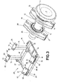
Figure 3 shows a perspective view of a tool for transporting a windturbine power train subset, according to a second particular embodiment of the present invention, wherein a first support element and a second support element, the subset, which includes the low-speed shaft, first and second bearings and first and second supports can be seen. -
Figure 4 shows a perspective view of a tool for transporting a windturbine power train subset, according to a third particular embodiment of the present invention, wherein a first support element and a second support element connected to each other can be seen along with the subset, which includes a low-speed shaft, first and second bearings and first and second supports about to be mounted in the tool. -
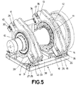
Figure 5 shows the tool object of the invention with the set loaded. -
Figures 6A and6B :Figure 6A shows a perspective view of the tool according to the invention, wherein the distances between the support surfaces and the resting surfaces are shown.Figure 6B shows a side view of the subset of the low-speed shaft, mounted on the tool of the invention, wherein the actual maximum width and the maximum transport width are shown. - Subsequently, with the help of the aforementioned attached
Figures 1-6B , a detailed description is provided of a preferred embodiment of a tool for transporting a windturbine power train subset, object of the present invention. - The tool of the invention is intended as a tool for transporting a windturbine power train subset. In particular, the tool is intended to transport a power train subset formed at least by the following elements: a shaft, called low-speed shaft (10), along with at least a first bearing (11) mounted on the low-speed shaft (10), and a first support (12) intended to support the first bearing (11) and the low-speed shaft (10) on a frame (not shown) of the wind turbine, and wherein the first support (12) comprises a first arm (13) and a second arm (14).
- To this end, the tool comprises a first support element (15) which, in turn, incorporates a first resting surface (16) to allow the first support element (15) to rest on a floor. The first support element (15) further comprises a first support surface (17) and a second support surface (18) so that the first arm (13) and the second arm (14), respectively, can rest on the same.
- Between the first support surface (17) and the first resting surface (16) is a first distance (D1), and between the second support surface (18) and said first resting surface (16) is a second distance (D2), wherein the first distance D1 and the second distance D2 are different. To define the first distance (D1) and the second distance (D2), homologous reference points are preferably taken on the first support surface (17) and on the second support surface (18), especially when said first (17) and second (18) support surfaces are not horizontal. For example, the lowest points of each one of them may be taken as a reference, as seen in the figures.
- In
Figure 6B one can see how the power train subset has an actual maximum width (AR), as well as a maximum transport width (AT), which corresponds to a projection of the actual maximum width (AR) on a horizontal plane. The previously described invention allows the power train subset to incline, from which the maximum transport width (AT) is smaller than the actual maximum width (AR). As a result, in an embodiment, it allows for the tool of the invention, along with the power train subset, to be introduced in a conventional transport container (not shown). - Preferably, the first support element (15) incorporates, on the first resting surface (16), a first support body (19) and a second support body (20), one on each right and left side of said first resting surface (16), the first support surface (17) situated on the first support body (19) and the second support surface (18) situated on the second support body (20).
- In this case, to help stabilise the power train on the first support element (15), the tool additionally comprises an additional support element (21) which, in turn, comprises an additional resting surface (22), and on said additional resting surface (22) an additional support body (23), provided with at least an additional support surface (24) on the upper part thereof for supporting one end of the low-speed shaft (10) longitudinally opposite the first support element (15).
- In another embodiment, the power train subset can additionally incorporate a second bearing (39) mounted on the low-speed shaft (10), as well as a second support (25) to fasten the second bearing (39) to the low-speed shaft (10), and which, in turn, is provided with a third arm (26) and a fourth arm (27). The tool additionally comprises a second support element (28) which, in turn, comprises a second resting surface (29) to allow the second support element (28) to rest on a floor in a stable way. The second support element (28) further comprises a third support surface (30) and a fourth support surface (31) so that the third arm (26) and the fourth arm (27) of the second support (25) can rest on the same.
- Between the third support surface (30) and the second resting surface (29) is a third distance D3, and between the fourth support surface (31) and said second resting surface (29) is a fourth distance D4, wherein the third distance D3 and the fourth distance D4 are different. Preferably, the third distance (D3) and the fourth distance (D4) are respectively equal to the first distance (D1) and the second distance (D2). In a similar way to what was previously mentioned for the case of the first distance (D1) and the second distance (D2), it holds that the homologous reference points are preferably taken on the third support surface (30) and the fourth support surface (31), especially when said third (30) and fourth (31) support surfaces are not horizontal. For example, the lowest points of each one of them may be taken as a reference, as seen in the figures.
- On the other hand, the second support element (28) preferably comprises, on the second resting surface (29), a third support body (32) and a fourth support body (33), one on each right and left side of said second resting surface (29), wherein the third support surface (30) is situated on the third support body (32) and the fourth support surface (31) is situated on the fourth support body (33).
- The tool preferably comprises a longitudinal direction of the tool, the first support body (19) and the second support body (20) being located on the same first section along the longitudinal direction of the tool. Likewise, the third support body (32) and the fourth support body (33) are preferably located on the same second section along the longitudinal direction of the tool.
- Preferably, any one, several, or all of the first (17), second (18), third (30) and fourth (31) support surfaces are inclined with respect to a horizontal plane.
- Likewise, also preferably, the support bodies (19, 20, 23, 32, 33) can comprise vertical beams. In particular, the first (19) and/or second (20) support bodies can comprise first beams, while the third (32) and fourth (33) support bodies can comprise second beams and the additional support body (23) can comprise a third beam.
- On the other hand, also preferably, any one, several, or all of the first (17), second (18), third (30) and fourth (31) support surfaces have a greater area than the surface of the corresponding arm (13, 14, 26, 27) that rests on the same.
- Likewise, on the other hand, the first (17), second (18), third (30), fourth (31) and additional (24) support surfaces comprise fastening means to be fastened in a separable way to the corresponding arms (13, 14, 26, 27). In particular, the first (17) and/or second (18) support surfaces can comprise first fastening means, while the third (30) and/or fourth (31) support surfaces can comprise second fastening means; and the additional support surface (24) can comprise third fastening means. The fastening means preferably comprise holes (34, 40, 42) made on the first (17), second (18), third (30), fourth (31) and additional (24) support surfaces; as well as bolts (35, 41) for cooperating with the holes (34, 40). In particular, the first fastening means comprise first bolts (35) and first holes (34), while the second fastening means comprise second bolts (41) and second holes (40), and the third fastening means comprise third bolts (not shown) and third holes (42). The holes (34, 40, 42) are preferably perpendicular to the corresponding first (17), second (18), third (30), fourth (31) and additional (24) surfaces thereof. As an alternative to the holes (34, 40, 42) and the bolts (35, 41), the fastening means can preferably comprise clamps. Instead of having third fastening means, the end of the low-speed shaft (10) could simply rest on the additional support surface (24).
- In relation to the preceding paragraph, the fastening means, in particular the holes (34, 40) can be used as reference points for measuring the heights (D1, D2, D3, D4).
- Preferably, the first (17), second (18), third (30), fourth (31) and additional (24) support surfaces comprise positioning elements (36, 43, 44) for longitudinally and/or transversally positioning the corresponding arms (13, 14, 26, 27) and, if applicable, the corresponding end of the low-speed shaft (10). The positioning elements (36, 43, 44) comprise: first positioning elements (36) for the first (17) and second (18) support surfaces, second positioning elements (43) for the third (30) and fourth (31) support surfaces; and third positioning elements (44) for the additional support surface (24). The positioning elements (36, 43, 44) are preferably located on a lower area, and/or on a side area of the first (17), second (18), third (30), fourth (31) and additional (24) support surfaces. The positioning elements (36, 43, 44) act as stops that limit the movement of the arms (13, 14, 26, 27) and of the low-speed shaft (10), if necessary.
- According to a preferred embodiment, as shown in
Figures 4 and5 , the first (17) and third (30) support surfaces can form part of a single body, for example a beam. Optionally, although in the figures the second (18) and fourth (31) support surfaces are shown as separated bodies, they can likewise form part of a single body, a beam for example. - Preferably, the first support element (15) and the second support element (28), and optionally, if necessary, the first support element (15) and the additional support element (21), are connected to each other. According to a first example, the tool incorporates a base (37), which the first resting surface (16) and/or the second resting surface (29) and/or the additional resting surface (22) form part of, or are connected to, wherein the first support element (15) and/or the additional support element (21) or the first support element (15) and/or the second support element (28) are able to be coupled or are coupled to said base (37).
- Alternatively, according to a second example, the first support element (15) and the second support element (28), as well as the first support element (15) and the additional support element (21) are able to be coupled or are coupled by means of connection elements (38), such as plates, bars, frames, etc.
- On the other hand, the power train subset can additionally comprise a gearbox (not shown), coupled to the low-speed shaft (10) and which comprises at least a lateral support element, which additionally comprises:
- third support means, which, in turn, comprise at least a third support body, and
- a third support surface, on each third support body, to support the lateral support element or elements of the gearbox.
Claims (29)
- A tool for transporting a windturbine power train subset, wherein the power train subset comprises: a low-speed shaft (10), at least a first bearing (11), mounted on the low-speed shaft (10), and at least a first support (12) for supporting the first bearing (11) on the low-speed shaft (10), said first support (12) being provided with a first arm (13) and a second arm (14), wherein the tool comprises a first support element (15), which, in turn, comprises:- a first resting surface (16) to allow the tool to rest on the floor, and- a first support surface (17) and a second support surface (18), configured to respectively support the first arm (13) and the second arm (14), the tool being characterised in that there is a first distance (D1) between the first support surface (17) and the first resting surface (16), wherein said first distance (D1) is different from a second distance (D2) between the second support surface (18) and said first resting surface (16).
- The tool for transporting a windturbine power train subset according to claim 1, characterised in that the first resting surface (16) comprises a right and left side, wherein the first support element (15) comprises on the first resting surface (16), a first support body (19) and a second support body (20), one on each right and left side of the first resting surface (16), wherein the first support surface (17) is situated on the first support body (19) and the second support surface (18) is situated on the second support body (20).
- The tool for transporting a windturbine power train subset according to claim 2, characterised in that it comprises a longitudinal direction of the tool, wherein the first support body (19) and the second support body (20) are located in the same first cross section along the longitudinal direction of the tool.
- The tool for transporting a windturbine power train subset according to any one of claims 1-3, characterised in that any one, several, or all of the first (17) and second (18) support surfaces are inclined with respect to a horizontal plane.
- The tool for transporting a windturbine power train subset according to any one of claims 1-4, characterised in that any on, several or all of the first (17) and second (18) support surfaces have a greater area than the surface of the corresponding first arm (13) and second arm (14) that rest on the same.
- The tool for transporting a windturbine power train subset according to any one of claims 1-5, characterised in that any one, several or all of the first (17) and second (18) support surfaces comprise first fastening means to be fastened to the corresponding first arm (13) and second arm (14) in a separable way.
- The tool for transporting a windturbine power train subset according to claim 6, characterised in that the first fastening means comprise:- first holes (34) made in the first (17) and second (18) support surfaces; and- first bolts (35) for cooperating with the first holes (34).
- The tool for transporting a windturbine power train subset according to claim 7, characterised in that the first holes (34) are perpendicular to the first (17) and second (18) support surfaces.
- The tool for transporting a windturbine power train subset according to any one of claims 1-8, characterised in that the first (17) and/or second (18) support surfaces comprise first positioning elements (36) for longitudinally and/or transversally positioning the first arm (13) and the second arm (14).
- The tool for transporting a windturbine power train subset according to claim 9, characterised in that the first positioning elements (36) are located in a lower area and/or in a side area of the first (17) and/or second (18) support surfaces.
- The tool for transporting a windturbine power train subset according to any one of claims 2-10, characterised in that the first (19) and second (20) support bodies comprise first vertical beams.
- The tool for transporting a windturbine power train subset according to any one of claims 1-11, which additionally comprises a base (37) which, in turn, comprises the first resting surface (16), the first support element (15) being able to be coupled to said base (37).
- The tool for transporting a windturbine power train subset according to any one of claims 1-12, characterised in that it additionally comprises an additional support element (21) which, in turn comprises:- an additional resting surface (22), and- on said additional resting surface (22), an additional support body (23) provided with at least one additional support surface (24) on the upper part for supporting one end of the low-speed shaft (10).
- The tool for transporting a windturbine power train subset according to claim 13, characterised in that it additionally comprises a base (37) which, in turn, comprises the additional resting surface (22), the additional support element (21) being able to be coupled to said base (37).
- The tool for transporting a power train subset of a wind turbine according to any one of claims 1-12, characterised in that the power train subset additionally comprises a second bearing (39), mounted on the low-speed shaft (10), and a second support (25), for fastening the second bearing (39) to the low-speed shaft (10), and which is provided with a third arm (26) and a fourth arm (27), wherein the tool additionally comprises a second support element (28) which, in turn, comprises:- a second resting surface (29), to allow the tool to rest on the floor, and- a third support surface (30) and a fourth support surface (31), configured to support the respective third arm (26) and fourth arm (27) on the same, wherein there is a third distance (D3) between the third support surface (30) and the second resting surface (29), said third distance (D3) being different from a fourth distance (D4) between the fourth support surface (31) and said second resting surface (29).
- The tool for transporting a windturbine power train subset according to claim 15, characterised in that the second support element (28) comprises, on the second resting surface (29), a third support body (32) and a fourth support body (33), one on each right and left side of said second resting surface (29), wherein the third support surface (30) is situated on the third support body (32) and the fourth support surface (31) is situated on the fourth support body (33).
- The tool for transporting a windturbine power train subset according to claim 16, characterised in that it comprises a longitudinal direction of the tool, wherein the third support body (32) and the fourth support body (33) are located in the same second cross section along the longitudinal direction of the tool.
- The tool for transporting a windturbine power train subset according to any one of claims 15-17, characterised in that any one, several or all of the third (30) and fourth (31) support surfaces are inclined with respect to a horizontal plane.
- The tool for transporting a windturbine power train subset according to any one of claims 15-18, characterised in that any one, several or all of the third (30) and fourth (31) support surfaces have a greater area than the surface of the corresponding third arm (26) and fourth arm (27) that rest on the same.
- The tool for transporting a windturbine power train subset according to any one of claims 15-19, characterised in that the third (30) and fourth (31) support surfaces comprise second fastening means to be fastened to the corresponding third arm (26) and fourth arm (27) in a separable way.
- The tool for transporting a windturbine power train subset according to claim 20, characterised in that the second fastening means comprise:- second holes (40) made in the third (30) and fourth (31) support surfaces; and- second bolts (41) for cooperating with the second holes (40).
- The tool for transporting a windturbine power train subset according to claim 21, characterised in that the second holes (40) are perpendicular to the third (30) and fourth (31) support surfaces.
- The tool for transporting a windturbine power train subset according to claims 6 or 20, characterised in that the fastening means comprise clamps.
- The tool for transporting a windturbine power train subset according to any one of claims 15-23, characterised in that the third (30) and fourth (31) support surfaces comprise second positioning elements (43) for longitudinally and/or transversally positioning the third arm (26) and the fourth arm (27).
- The tool for transporting a windturbine power train subset according to claim 24, characterised in that the second positioning elements (43) are located in a lower area and/or in a side area of the third (30) and/or fourth (31) support surfaces.
- The tool for transporting a windturbine power train subset according to any one of claims 16-25, characterised in that the third (32) and fourth (33) support bodies comprise second vertical beams.
- The tool for transporting a windturbine power train subset according to any one of claims 15-26, which additionally comprises a base (37) which, in turn, comprises the second resting surface (29), the second support element (28) being able to be coupled to said base (37).
- The tool for transporting a windturbine power train subset according to claims 1 and 15, characterised in that the third distance (D3) is substantially equal to the first distance (D1) and/or the fourth distance (D4) is substantially equal to the second distance (D2).
- The tool for transporting a windturbine power train subset according to claim 1, 13 and 15, characterised in that it additionally comprises a base (37) which, in turn, comprises the first resting surface (16) and the second resting surface (29), or the first resting surface (16) and the additional resting surface (22), the first support element (15), the second support element (28) and the additional support element (21) respectively being able to be coupled to said base (37).
Applications Claiming Priority (1)
| Application Number | Priority Date | Filing Date | Title |
|---|---|---|---|
| ES201731530U ES1203662Y (en) | 2017-12-18 | 2017-12-18 | TRANSPORTATION OF A SUBCONJUNTO OF A POWER SUPPLY TRAIN AN AEROGENERATOR |
Publications (2)
| Publication Number | Publication Date |
|---|---|
| EP3499028A1 true EP3499028A1 (en) | 2019-06-19 |
| EP3499028B1 EP3499028B1 (en) | 2024-05-01 |
Family
ID=60992870
Family Applications (1)
| Application Number | Title | Priority Date | Filing Date |
|---|---|---|---|
| EP18382813.6A Active EP3499028B1 (en) | 2017-12-18 | 2018-11-16 | Tool for transporting a windturbine power train subset |
Country Status (4)
| Country | Link |
|---|---|
| US (1) | US10935000B2 (en) |
| EP (1) | EP3499028B1 (en) |
| DK (1) | DK3499028T3 (en) |
| ES (2) | ES1203662Y (en) |
Families Citing this family (1)
| Publication number | Priority date | Publication date | Assignee | Title |
|---|---|---|---|---|
| US11668430B2 (en) * | 2020-09-30 | 2023-06-06 | Robert Green | Engine mount stand |
Citations (4)
| Publication number | Priority date | Publication date | Assignee | Title |
|---|---|---|---|---|
| KR20120102213A (en) * | 2011-03-08 | 2012-09-18 | 주식회사 평산 | A fixture of shaft for wind-driven generator |
| DE102011013844A1 (en) * | 2011-03-14 | 2012-09-20 | Repower Systems Ag | Caddy for the drive train of a wind turbine |
| DE102013003191A1 (en) * | 2013-02-26 | 2014-09-11 | F.A. KRUSE jun. ENERGY SERVICES + LOGISTICS GmbH | Combination of a hub trim segment of a wind turbine and a hub trim segment carrying caddy and transport frame and method for transporting a hub trim segment of a wind turbine |
| US20150159631A1 (en) * | 2012-06-10 | 2015-06-11 | Vestas Wind Systems A/S | Main bearing arrangement for a wind turbine |
Family Cites Families (7)
| Publication number | Priority date | Publication date | Assignee | Title |
|---|---|---|---|---|
| US4804162A (en) * | 1987-06-29 | 1989-02-14 | Joseph M. Rice | Adjustable engine support |
| JP4363799B2 (en) * | 2001-06-08 | 2009-11-11 | 株式会社東芝 | Turbine assembly transport stand, turbine assembly method using the stand, and transport method |
| US7726182B1 (en) * | 2008-12-30 | 2010-06-01 | Newlin Mark A | Engine test stand assembly |
| KR20120063777A (en) * | 2010-12-08 | 2012-06-18 | 현대자동차주식회사 | Vehicle body moving cart |
| KR101482573B1 (en) * | 2013-03-22 | 2015-01-21 | 두산중공업 주식회사 | Supporting device for a gas turbine |
| KR101459465B1 (en) * | 2013-06-14 | 2014-11-07 | 현대자동차 주식회사 | Loading jig of trunk lid and tailgate |
| US8876448B1 (en) * | 2013-08-28 | 2014-11-04 | General Electric Company | Gas turbine half-casing shipping fixture |
-
2017
- 2017-12-18 ES ES201731530U patent/ES1203662Y/en active Active
-
2018
- 2018-11-16 EP EP18382813.6A patent/EP3499028B1/en active Active
- 2018-11-16 DK DK18382813.6T patent/DK3499028T3/en active
- 2018-11-16 ES ES18382813T patent/ES2983531T3/en active Active
- 2018-12-18 US US16/223,851 patent/US10935000B2/en active Active
Patent Citations (4)
| Publication number | Priority date | Publication date | Assignee | Title |
|---|---|---|---|---|
| KR20120102213A (en) * | 2011-03-08 | 2012-09-18 | 주식회사 평산 | A fixture of shaft for wind-driven generator |
| DE102011013844A1 (en) * | 2011-03-14 | 2012-09-20 | Repower Systems Ag | Caddy for the drive train of a wind turbine |
| US20150159631A1 (en) * | 2012-06-10 | 2015-06-11 | Vestas Wind Systems A/S | Main bearing arrangement for a wind turbine |
| DE102013003191A1 (en) * | 2013-02-26 | 2014-09-11 | F.A. KRUSE jun. ENERGY SERVICES + LOGISTICS GmbH | Combination of a hub trim segment of a wind turbine and a hub trim segment carrying caddy and transport frame and method for transporting a hub trim segment of a wind turbine |
Also Published As
| Publication number | Publication date |
|---|---|
| ES2983531T3 (en) | 2024-10-23 |
| DK3499028T3 (en) | 2024-07-08 |
| ES1203662Y (en) | 2018-04-18 |
| BR202018076433U2 (en) | 2019-06-25 |
| US20190186466A1 (en) | 2019-06-20 |
| ES1203662U (en) | 2018-01-24 |
| EP3499028B1 (en) | 2024-05-01 |
| US10935000B2 (en) | 2021-03-02 |
Similar Documents
| Publication | Publication Date | Title |
|---|---|---|
| US10473363B2 (en) | Node, support frame, system and method | |
| JP6476740B2 (en) | Solar power generation panel and method for manufacturing solar power generation apparatus | |
| US8506218B2 (en) | Transporting tool for tower sections of a wind turbine | |
| US8876448B1 (en) | Gas turbine half-casing shipping fixture | |
| JP6942264B2 (en) | Flange frames and assembly sets and methods for pre-assembling and / or transporting and / or assembling wind turbine tower segments. | |
| US9920748B2 (en) | Method and tool for assembling tower elements | |
| EP2971355B1 (en) | Rail system for jacking tower | |
| KR102450054B1 (en) | Support assembly for turbine shipping/operation | |
| US10935000B2 (en) | Tool for transporting a wind turbine power train subset | |
| CN102628429A (en) | Transport structure and methods for transporting and/or lift-ing a large scale generator | |
| CA2781328C (en) | Node, support frame, system and method | |
| US20260009256A1 (en) | Tower sheet assembly, tower section, and tower transportation and assembly method | |
| CN104471340A (en) | Air Cooled Condenser Fan Platform Subassembly | |
| CN107444746A (en) | For the pallet of big machinery and its transportation resources and gradual pallet | |
| EP4348047B1 (en) | Wind turbine with auxiliary units | |
| US20140144276A1 (en) | Parallel manipulator | |
| US10927822B2 (en) | Frame for carrying a load in a wind turbine | |
| JP6205513B1 (en) | Spherical sliding bearing construction method, spherical sliding bearing with fixing jig, and fixing jig | |
| US20210115903A1 (en) | Wind turbine mast section, wind turbine mast and assembly method | |
| CN105290675A (en) | Assembly welding template structure of steam cooling separator and steam cooling separator device | |
| JP6619263B2 (en) | Hanging beam device | |
| CN209195602U (en) | The engineroom flat and wind power generating set of wind power generating set | |
| US11215166B2 (en) | Assembly assisting device for assisting of the assembling of two wind turbine components of a wind turbine and method for assembling of the two wind turbine components | |
| CN211544404U (en) | Helicopter propeller hub journal keeps support | |
| CN202295337U (en) | Satellite terminal display push-and-pull device |
Legal Events
| Date | Code | Title | Description |
|---|---|---|---|
| PUAI | Public reference made under article 153(3) epc to a published international application that has entered the european phase |
Free format text: ORIGINAL CODE: 0009012 |
|
| STAA | Information on the status of an ep patent application or granted ep patent |
Free format text: STATUS: THE APPLICATION HAS BEEN PUBLISHED |
|
| AK | Designated contracting states |
Kind code of ref document: A1 Designated state(s): AL AT BE BG CH CY CZ DE DK EE ES FI FR GB GR HR HU IE IS IT LI LT LU LV MC MK MT NL NO PL PT RO RS SE SI SK SM TR |
|
| AX | Request for extension of the european patent |
Extension state: BA ME |
|
| STAA | Information on the status of an ep patent application or granted ep patent |
Free format text: STATUS: REQUEST FOR EXAMINATION WAS MADE |
|
| 17P | Request for examination filed |
Effective date: 20200331 |
|
| RBV | Designated contracting states (corrected) |
Designated state(s): AL AT BE BG CH CY CZ DE DK EE ES FI FR GB GR HR HU IE IS IT LI LT LU LV MC MK MT NL NO PL PT RO RS SE SI SK SM TR |
|
| STAA | Information on the status of an ep patent application or granted ep patent |
Free format text: STATUS: EXAMINATION IS IN PROGRESS |
|
| 17Q | First examination report despatched |
Effective date: 20220406 |
|
| P01 | Opt-out of the competence of the unified patent court (upc) registered |
Effective date: 20230530 |
|
| GRAP | Despatch of communication of intention to grant a patent |
Free format text: ORIGINAL CODE: EPIDOSNIGR1 |
|
| STAA | Information on the status of an ep patent application or granted ep patent |
Free format text: STATUS: GRANT OF PATENT IS INTENDED |
|
| INTG | Intention to grant announced |
Effective date: 20231201 |
|
| RIN1 | Information on inventor provided before grant (corrected) |
Inventor name: NUNEZ POLO, MIGUEL Inventor name: GARCIA SAYES, JOSE MIGUEL Inventor name: ARLABAN GABEIRAS, TERESA Inventor name: GASTON LUJAMBO, ANDER Inventor name: IRURITA LOYARTE, JUAN Inventor name: ARRAZTOA MAGANA, UNAI Inventor name: RUEDA ALZUGARAY, DIEGO Inventor name: VALLE MARTIN, ANDRES Inventor name: AUGUSTO LIZARRAGA, NURIA |
|
| GRAS | Grant fee paid |
Free format text: ORIGINAL CODE: EPIDOSNIGR3 |
|
| GRAA | (expected) grant |
Free format text: ORIGINAL CODE: 0009210 |
|
| STAA | Information on the status of an ep patent application or granted ep patent |
Free format text: STATUS: THE PATENT HAS BEEN GRANTED |
|
| AK | Designated contracting states |
Kind code of ref document: B1 Designated state(s): AL AT BE BG CH CY CZ DE DK EE ES FI FR GB GR HR HU IE IS IT LI LT LU LV MC MK MT NL NO PL PT RO RS SE SI SK SM TR |
|
| REG | Reference to a national code |
Ref country code: GB Ref legal event code: FG4D |
|
| REG | Reference to a national code |
Ref country code: CH Ref legal event code: EP |
|
| REG | Reference to a national code |
Ref country code: IE Ref legal event code: FG4D |
|
| REG | Reference to a national code |
Ref country code: DE Ref legal event code: R096 Ref document number: 602018068830 Country of ref document: DE |
|
| REG | Reference to a national code |
Ref country code: DK Ref legal event code: T3 Effective date: 20240704 |
|
| REG | Reference to a national code |
Ref country code: LT Ref legal event code: MG9D |
|
| REG | Reference to a national code |
Ref country code: NL Ref legal event code: MP Effective date: 20240501 |
|
| PG25 | Lapsed in a contracting state [announced via postgrant information from national office to epo] |
Ref country code: IS Free format text: LAPSE BECAUSE OF FAILURE TO SUBMIT A TRANSLATION OF THE DESCRIPTION OR TO PAY THE FEE WITHIN THE PRESCRIBED TIME-LIMIT Effective date: 20240901 |
|
| PG25 | Lapsed in a contracting state [announced via postgrant information from national office to epo] |
Ref country code: BG Free format text: LAPSE BECAUSE OF FAILURE TO SUBMIT A TRANSLATION OF THE DESCRIPTION OR TO PAY THE FEE WITHIN THE PRESCRIBED TIME-LIMIT Effective date: 20240501 |
|
| PG25 | Lapsed in a contracting state [announced via postgrant information from national office to epo] |
Ref country code: FI Free format text: LAPSE BECAUSE OF FAILURE TO SUBMIT A TRANSLATION OF THE DESCRIPTION OR TO PAY THE FEE WITHIN THE PRESCRIBED TIME-LIMIT Effective date: 20240501 Ref country code: HR Free format text: LAPSE BECAUSE OF FAILURE TO SUBMIT A TRANSLATION OF THE DESCRIPTION OR TO PAY THE FEE WITHIN THE PRESCRIBED TIME-LIMIT Effective date: 20240501 |
|
| PG25 | Lapsed in a contracting state [announced via postgrant information from national office to epo] |
Ref country code: GR Free format text: LAPSE BECAUSE OF FAILURE TO SUBMIT A TRANSLATION OF THE DESCRIPTION OR TO PAY THE FEE WITHIN THE PRESCRIBED TIME-LIMIT Effective date: 20240802 |
|
| PG25 | Lapsed in a contracting state [announced via postgrant information from national office to epo] |
Ref country code: PT Free format text: LAPSE BECAUSE OF FAILURE TO SUBMIT A TRANSLATION OF THE DESCRIPTION OR TO PAY THE FEE WITHIN THE PRESCRIBED TIME-LIMIT Effective date: 20240902 |
|
| REG | Reference to a national code |
Ref country code: AT Ref legal event code: MK05 Ref document number: 1682655 Country of ref document: AT Kind code of ref document: T Effective date: 20240501 |
|
| PG25 | Lapsed in a contracting state [announced via postgrant information from national office to epo] |
Ref country code: NL Free format text: LAPSE BECAUSE OF FAILURE TO SUBMIT A TRANSLATION OF THE DESCRIPTION OR TO PAY THE FEE WITHIN THE PRESCRIBED TIME-LIMIT Effective date: 20240501 |
|
| REG | Reference to a national code |
Ref country code: ES Ref legal event code: FG2A Ref document number: 2983531 Country of ref document: ES Kind code of ref document: T3 Effective date: 20241023 |
|
| PG25 | Lapsed in a contracting state [announced via postgrant information from national office to epo] |
Ref country code: AT Free format text: LAPSE BECAUSE OF FAILURE TO SUBMIT A TRANSLATION OF THE DESCRIPTION OR TO PAY THE FEE WITHIN THE PRESCRIBED TIME-LIMIT Effective date: 20240501 |
|
| PG25 | Lapsed in a contracting state [announced via postgrant information from national office to epo] |
Ref country code: PL Free format text: LAPSE BECAUSE OF FAILURE TO SUBMIT A TRANSLATION OF THE DESCRIPTION OR TO PAY THE FEE WITHIN THE PRESCRIBED TIME-LIMIT Effective date: 20240501 |
|
| PG25 | Lapsed in a contracting state [announced via postgrant information from national office to epo] |
Ref country code: LV Free format text: LAPSE BECAUSE OF FAILURE TO SUBMIT A TRANSLATION OF THE DESCRIPTION OR TO PAY THE FEE WITHIN THE PRESCRIBED TIME-LIMIT Effective date: 20240501 |
|
| PG25 | Lapsed in a contracting state [announced via postgrant information from national office to epo] |
Ref country code: PT Free format text: LAPSE BECAUSE OF FAILURE TO SUBMIT A TRANSLATION OF THE DESCRIPTION OR TO PAY THE FEE WITHIN THE PRESCRIBED TIME-LIMIT Effective date: 20240902 Ref country code: PL Free format text: LAPSE BECAUSE OF FAILURE TO SUBMIT A TRANSLATION OF THE DESCRIPTION OR TO PAY THE FEE WITHIN THE PRESCRIBED TIME-LIMIT Effective date: 20240501 Ref country code: NO Free format text: LAPSE BECAUSE OF FAILURE TO SUBMIT A TRANSLATION OF THE DESCRIPTION OR TO PAY THE FEE WITHIN THE PRESCRIBED TIME-LIMIT Effective date: 20240801 Ref country code: NL Free format text: LAPSE BECAUSE OF FAILURE TO SUBMIT A TRANSLATION OF THE DESCRIPTION OR TO PAY THE FEE WITHIN THE PRESCRIBED TIME-LIMIT Effective date: 20240501 Ref country code: LV Free format text: LAPSE BECAUSE OF FAILURE TO SUBMIT A TRANSLATION OF THE DESCRIPTION OR TO PAY THE FEE WITHIN THE PRESCRIBED TIME-LIMIT Effective date: 20240501 Ref country code: IS Free format text: LAPSE BECAUSE OF FAILURE TO SUBMIT A TRANSLATION OF THE DESCRIPTION OR TO PAY THE FEE WITHIN THE PRESCRIBED TIME-LIMIT Effective date: 20240901 Ref country code: HR Free format text: LAPSE BECAUSE OF FAILURE TO SUBMIT A TRANSLATION OF THE DESCRIPTION OR TO PAY THE FEE WITHIN THE PRESCRIBED TIME-LIMIT Effective date: 20240501 Ref country code: GR Free format text: LAPSE BECAUSE OF FAILURE TO SUBMIT A TRANSLATION OF THE DESCRIPTION OR TO PAY THE FEE WITHIN THE PRESCRIBED TIME-LIMIT Effective date: 20240802 Ref country code: FI Free format text: LAPSE BECAUSE OF FAILURE TO SUBMIT A TRANSLATION OF THE DESCRIPTION OR TO PAY THE FEE WITHIN THE PRESCRIBED TIME-LIMIT Effective date: 20240501 Ref country code: BG Free format text: LAPSE BECAUSE OF FAILURE TO SUBMIT A TRANSLATION OF THE DESCRIPTION OR TO PAY THE FEE WITHIN THE PRESCRIBED TIME-LIMIT Effective date: 20240501 Ref country code: AT Free format text: LAPSE BECAUSE OF FAILURE TO SUBMIT A TRANSLATION OF THE DESCRIPTION OR TO PAY THE FEE WITHIN THE PRESCRIBED TIME-LIMIT Effective date: 20240501 Ref country code: RS Free format text: LAPSE BECAUSE OF FAILURE TO SUBMIT A TRANSLATION OF THE DESCRIPTION OR TO PAY THE FEE WITHIN THE PRESCRIBED TIME-LIMIT Effective date: 20240801 |
|
| PG25 | Lapsed in a contracting state [announced via postgrant information from national office to epo] |
Ref country code: EE Free format text: LAPSE BECAUSE OF FAILURE TO SUBMIT A TRANSLATION OF THE DESCRIPTION OR TO PAY THE FEE WITHIN THE PRESCRIBED TIME-LIMIT Effective date: 20240501 |
|
| PG25 | Lapsed in a contracting state [announced via postgrant information from national office to epo] |
Ref country code: CZ Free format text: LAPSE BECAUSE OF FAILURE TO SUBMIT A TRANSLATION OF THE DESCRIPTION OR TO PAY THE FEE WITHIN THE PRESCRIBED TIME-LIMIT Effective date: 20240501 |
|
| PG25 | Lapsed in a contracting state [announced via postgrant information from national office to epo] |
Ref country code: RO Free format text: LAPSE BECAUSE OF FAILURE TO SUBMIT A TRANSLATION OF THE DESCRIPTION OR TO PAY THE FEE WITHIN THE PRESCRIBED TIME-LIMIT Effective date: 20240501 Ref country code: SK Free format text: LAPSE BECAUSE OF FAILURE TO SUBMIT A TRANSLATION OF THE DESCRIPTION OR TO PAY THE FEE WITHIN THE PRESCRIBED TIME-LIMIT Effective date: 20240501 |
|
| PG25 | Lapsed in a contracting state [announced via postgrant information from national office to epo] |
Ref country code: SM Free format text: LAPSE BECAUSE OF FAILURE TO SUBMIT A TRANSLATION OF THE DESCRIPTION OR TO PAY THE FEE WITHIN THE PRESCRIBED TIME-LIMIT Effective date: 20240501 |
|
| PG25 | Lapsed in a contracting state [announced via postgrant information from national office to epo] |
Ref country code: SM Free format text: LAPSE BECAUSE OF FAILURE TO SUBMIT A TRANSLATION OF THE DESCRIPTION OR TO PAY THE FEE WITHIN THE PRESCRIBED TIME-LIMIT Effective date: 20240501 Ref country code: SK Free format text: LAPSE BECAUSE OF FAILURE TO SUBMIT A TRANSLATION OF THE DESCRIPTION OR TO PAY THE FEE WITHIN THE PRESCRIBED TIME-LIMIT Effective date: 20240501 Ref country code: RO Free format text: LAPSE BECAUSE OF FAILURE TO SUBMIT A TRANSLATION OF THE DESCRIPTION OR TO PAY THE FEE WITHIN THE PRESCRIBED TIME-LIMIT Effective date: 20240501 Ref country code: EE Free format text: LAPSE BECAUSE OF FAILURE TO SUBMIT A TRANSLATION OF THE DESCRIPTION OR TO PAY THE FEE WITHIN THE PRESCRIBED TIME-LIMIT Effective date: 20240501 Ref country code: CZ Free format text: LAPSE BECAUSE OF FAILURE TO SUBMIT A TRANSLATION OF THE DESCRIPTION OR TO PAY THE FEE WITHIN THE PRESCRIBED TIME-LIMIT Effective date: 20240501 |
|
| REG | Reference to a national code |
Ref country code: DE Ref legal event code: R097 Ref document number: 602018068830 Country of ref document: DE |
|
| PG25 | Lapsed in a contracting state [announced via postgrant information from national office to epo] |
Ref country code: IT Free format text: LAPSE BECAUSE OF FAILURE TO SUBMIT A TRANSLATION OF THE DESCRIPTION OR TO PAY THE FEE WITHIN THE PRESCRIBED TIME-LIMIT Effective date: 20240501 |
|
| PLBE | No opposition filed within time limit |
Free format text: ORIGINAL CODE: 0009261 |
|
| STAA | Information on the status of an ep patent application or granted ep patent |
Free format text: STATUS: NO OPPOSITION FILED WITHIN TIME LIMIT |
|
| 26N | No opposition filed |
Effective date: 20250204 |
|
| PG25 | Lapsed in a contracting state [announced via postgrant information from national office to epo] |
Ref country code: SI Free format text: LAPSE BECAUSE OF FAILURE TO SUBMIT A TRANSLATION OF THE DESCRIPTION OR TO PAY THE FEE WITHIN THE PRESCRIBED TIME-LIMIT Effective date: 20240501 |
|
| REG | Reference to a national code |
Ref country code: CH Ref legal event code: PL |
|
| PG25 | Lapsed in a contracting state [announced via postgrant information from national office to epo] |
Ref country code: MC Free format text: LAPSE BECAUSE OF FAILURE TO SUBMIT A TRANSLATION OF THE DESCRIPTION OR TO PAY THE FEE WITHIN THE PRESCRIBED TIME-LIMIT Effective date: 20240501 |
|
| PG25 | Lapsed in a contracting state [announced via postgrant information from national office to epo] |
Ref country code: LU Free format text: LAPSE BECAUSE OF NON-PAYMENT OF DUE FEES Effective date: 20241116 |
|
| REG | Reference to a national code |
Ref country code: CH Ref legal event code: PL |
|
| GBPC | Gb: european patent ceased through non-payment of renewal fee |
Effective date: 20241116 |
|
| PG25 | Lapsed in a contracting state [announced via postgrant information from national office to epo] |
Ref country code: CH Free format text: LAPSE BECAUSE OF NON-PAYMENT OF DUE FEES Effective date: 20241130 |
|
| REG | Reference to a national code |
Ref country code: BE Ref legal event code: MM Effective date: 20241130 |
|
| PG25 | Lapsed in a contracting state [announced via postgrant information from national office to epo] |
Ref country code: SE Free format text: LAPSE BECAUSE OF FAILURE TO SUBMIT A TRANSLATION OF THE DESCRIPTION OR TO PAY THE FEE WITHIN THE PRESCRIBED TIME-LIMIT Effective date: 20240501 |
|
| PG25 | Lapsed in a contracting state [announced via postgrant information from national office to epo] |
Ref country code: GB Free format text: LAPSE BECAUSE OF NON-PAYMENT OF DUE FEES Effective date: 20241116 Ref country code: BE Free format text: LAPSE BECAUSE OF NON-PAYMENT OF DUE FEES Effective date: 20241130 |
|
| PG25 | Lapsed in a contracting state [announced via postgrant information from national office to epo] |
Ref country code: FR Free format text: LAPSE BECAUSE OF NON-PAYMENT OF DUE FEES Effective date: 20241130 |
|
| PG25 | Lapsed in a contracting state [announced via postgrant information from national office to epo] |
Ref country code: IE Free format text: LAPSE BECAUSE OF NON-PAYMENT OF DUE FEES Effective date: 20241116 |
|
| PGFP | Annual fee paid to national office [announced via postgrant information from national office to epo] |
Ref country code: DE Payment date: 20251118 Year of fee payment: 8 |
|
| PGFP | Annual fee paid to national office [announced via postgrant information from national office to epo] |
Ref country code: DK Payment date: 20251119 Year of fee payment: 8 |
|
| PGFP | Annual fee paid to national office [announced via postgrant information from national office to epo] |
Ref country code: ES Payment date: 20251216 Year of fee payment: 8 |
|
| PG25 | Lapsed in a contracting state [announced via postgrant information from national office to epo] |
Ref country code: HU Free format text: LAPSE BECAUSE OF FAILURE TO SUBMIT A TRANSLATION OF THE DESCRIPTION OR TO PAY THE FEE WITHIN THE PRESCRIBED TIME-LIMIT; INVALID AB INITIO Effective date: 20181116 |
|
| PG25 | Lapsed in a contracting state [announced via postgrant information from national office to epo] |
Ref country code: CY Free format text: LAPSE BECAUSE OF FAILURE TO SUBMIT A TRANSLATION OF THE DESCRIPTION OR TO PAY THE FEE WITHIN THE PRESCRIBED TIME-LIMIT; INVALID AB INITIO Effective date: 20181116 |
|
| PG25 | Lapsed in a contracting state [announced via postgrant information from national office to epo] |
Ref country code: TR Free format text: LAPSE BECAUSE OF FAILURE TO SUBMIT A TRANSLATION OF THE DESCRIPTION OR TO PAY THE FEE WITHIN THE PRESCRIBED TIME-LIMIT Effective date: 20240501 |
|
| PG25 | Lapsed in a contracting state [announced via postgrant information from national office to epo] |
Ref country code: LT Free format text: LAPSE BECAUSE OF FAILURE TO SUBMIT A TRANSLATION OF THE DESCRIPTION OR TO PAY THE FEE WITHIN THE PRESCRIBED TIME-LIMIT Effective date: 20240501 |