EP3499010A1 - Method and device for controlling vehicle including idle stop and go function - Google Patents
Method and device for controlling vehicle including idle stop and go function Download PDFInfo
- Publication number
- EP3499010A1 EP3499010A1 EP18182393.1A EP18182393A EP3499010A1 EP 3499010 A1 EP3499010 A1 EP 3499010A1 EP 18182393 A EP18182393 A EP 18182393A EP 3499010 A1 EP3499010 A1 EP 3499010A1
- Authority
- EP
- European Patent Office
- Prior art keywords
- signal
- state
- vehicle
- engine
- idle stop
- Prior art date
- Legal status (The legal status is an assumption and is not a legal conclusion. Google has not performed a legal analysis and makes no representation as to the accuracy of the status listed.)
- Granted
Links
- 238000000034 method Methods 0.000 title claims abstract description 25
- 239000000446 fuel Substances 0.000 claims abstract description 69
- 238000001514 detection method Methods 0.000 claims abstract description 21
- 230000004044 response Effects 0.000 claims abstract description 7
- 230000005540 biological transmission Effects 0.000 claims description 26
- 230000006870 function Effects 0.000 description 24
- 230000001133 acceleration Effects 0.000 description 10
- 238000002347 injection Methods 0.000 description 7
- 239000007924 injection Substances 0.000 description 7
- CURLTUGMZLYLDI-UHFFFAOYSA-N Carbon dioxide Chemical compound O=C=O CURLTUGMZLYLDI-UHFFFAOYSA-N 0.000 description 6
- 230000006866 deterioration Effects 0.000 description 5
- 230000005611 electricity Effects 0.000 description 5
- 229910002092 carbon dioxide Inorganic materials 0.000 description 3
- 239000001569 carbon dioxide Substances 0.000 description 3
- 230000001172 regenerating effect Effects 0.000 description 3
- 238000002485 combustion reaction Methods 0.000 description 2
- 238000010586 diagram Methods 0.000 description 2
- 239000007858 starting material Substances 0.000 description 2
- 230000008901 benefit Effects 0.000 description 1
- 239000002826 coolant Substances 0.000 description 1
- 230000000881 depressing effect Effects 0.000 description 1
- 230000000994 depressogenic effect Effects 0.000 description 1
- 230000009977 dual effect Effects 0.000 description 1
- 230000002401 inhibitory effect Effects 0.000 description 1
- 230000004048 modification Effects 0.000 description 1
- 238000012986 modification Methods 0.000 description 1
- 230000007935 neutral effect Effects 0.000 description 1
- 230000008569 process Effects 0.000 description 1
- 239000000126 substance Substances 0.000 description 1
Images
Classifications
-
- B—PERFORMING OPERATIONS; TRANSPORTING
- B60—VEHICLES IN GENERAL
- B60W—CONJOINT CONTROL OF VEHICLE SUB-UNITS OF DIFFERENT TYPE OR DIFFERENT FUNCTION; CONTROL SYSTEMS SPECIALLY ADAPTED FOR HYBRID VEHICLES; ROAD VEHICLE DRIVE CONTROL SYSTEMS FOR PURPOSES NOT RELATED TO THE CONTROL OF A PARTICULAR SUB-UNIT
- B60W30/00—Purposes of road vehicle drive control systems not related to the control of a particular sub-unit, e.g. of systems using conjoint control of vehicle sub-units, or advanced driver assistance systems for ensuring comfort, stability and safety or drive control systems for propelling or retarding the vehicle
- B60W30/18—Propelling the vehicle
- B60W30/18009—Propelling the vehicle related to particular drive situations
- B60W30/18054—Propelling the vehicle related to particular drive situations at stand still, e.g. engine in idling state
-
- B—PERFORMING OPERATIONS; TRANSPORTING
- B60—VEHICLES IN GENERAL
- B60K—ARRANGEMENT OR MOUNTING OF PROPULSION UNITS OR OF TRANSMISSIONS IN VEHICLES; ARRANGEMENT OR MOUNTING OF PLURAL DIVERSE PRIME-MOVERS IN VEHICLES; AUXILIARY DRIVES FOR VEHICLES; INSTRUMENTATION OR DASHBOARDS FOR VEHICLES; ARRANGEMENTS IN CONNECTION WITH COOLING, AIR INTAKE, GAS EXHAUST OR FUEL SUPPLY OF PROPULSION UNITS IN VEHICLES
- B60K6/00—Arrangement or mounting of plural diverse prime-movers for mutual or common propulsion, e.g. hybrid propulsion systems comprising electric motors and internal combustion engines ; Control systems therefor, i.e. systems controlling two or more prime movers, or controlling one of these prime movers and any of the transmission, drive or drive units Informative references: mechanical gearings with secondary electric drive F16H3/72; arrangements for handling mechanical energy structurally associated with the dynamo-electric machine H02K7/00; machines comprising structurally interrelated motor and generator parts H02K51/00; dynamo-electric machines not otherwise provided for in H02K see H02K99/00
- B60K6/20—Arrangement or mounting of plural diverse prime-movers for mutual or common propulsion, e.g. hybrid propulsion systems comprising electric motors and internal combustion engines ; Control systems therefor, i.e. systems controlling two or more prime movers, or controlling one of these prime movers and any of the transmission, drive or drive units Informative references: mechanical gearings with secondary electric drive F16H3/72; arrangements for handling mechanical energy structurally associated with the dynamo-electric machine H02K7/00; machines comprising structurally interrelated motor and generator parts H02K51/00; dynamo-electric machines not otherwise provided for in H02K see H02K99/00 the prime-movers consisting of electric motors and internal combustion engines, e.g. HEVs
- B60K6/42—Arrangement or mounting of plural diverse prime-movers for mutual or common propulsion, e.g. hybrid propulsion systems comprising electric motors and internal combustion engines ; Control systems therefor, i.e. systems controlling two or more prime movers, or controlling one of these prime movers and any of the transmission, drive or drive units Informative references: mechanical gearings with secondary electric drive F16H3/72; arrangements for handling mechanical energy structurally associated with the dynamo-electric machine H02K7/00; machines comprising structurally interrelated motor and generator parts H02K51/00; dynamo-electric machines not otherwise provided for in H02K see H02K99/00 the prime-movers consisting of electric motors and internal combustion engines, e.g. HEVs characterised by the architecture of the hybrid electric vehicle
- B60K6/48—Parallel type
- B60K6/485—Motor-assist type
-
- F—MECHANICAL ENGINEERING; LIGHTING; HEATING; WEAPONS; BLASTING
- F02—COMBUSTION ENGINES; HOT-GAS OR COMBUSTION-PRODUCT ENGINE PLANTS
- F02N—STARTING OF COMBUSTION ENGINES; STARTING AIDS FOR SUCH ENGINES, NOT OTHERWISE PROVIDED FOR
- F02N11/00—Starting of engines by means of electric motors
- F02N11/08—Circuits or control means specially adapted for starting of engines
- F02N11/0814—Circuits or control means specially adapted for starting of engines comprising means for controlling automatic idle-start-stop
- F02N11/0818—Conditions for starting or stopping the engine or for deactivating the idle-start-stop mode
-
- B—PERFORMING OPERATIONS; TRANSPORTING
- B60—VEHICLES IN GENERAL
- B60T—VEHICLE BRAKE CONTROL SYSTEMS OR PARTS THEREOF; BRAKE CONTROL SYSTEMS OR PARTS THEREOF, IN GENERAL; ARRANGEMENT OF BRAKING ELEMENTS ON VEHICLES IN GENERAL; PORTABLE DEVICES FOR PREVENTING UNWANTED MOVEMENT OF VEHICLES; VEHICLE MODIFICATIONS TO FACILITATE COOLING OF BRAKES
- B60T7/00—Brake-action initiating means
- B60T7/02—Brake-action initiating means for personal initiation
- B60T7/04—Brake-action initiating means for personal initiation foot actuated
- B60T7/042—Brake-action initiating means for personal initiation foot actuated by electrical means, e.g. using travel or force sensors
-
- B—PERFORMING OPERATIONS; TRANSPORTING
- B60—VEHICLES IN GENERAL
- B60W—CONJOINT CONTROL OF VEHICLE SUB-UNITS OF DIFFERENT TYPE OR DIFFERENT FUNCTION; CONTROL SYSTEMS SPECIALLY ADAPTED FOR HYBRID VEHICLES; ROAD VEHICLE DRIVE CONTROL SYSTEMS FOR PURPOSES NOT RELATED TO THE CONTROL OF A PARTICULAR SUB-UNIT
- B60W10/00—Conjoint control of vehicle sub-units of different type or different function
- B60W10/04—Conjoint control of vehicle sub-units of different type or different function including control of propulsion units
- B60W10/06—Conjoint control of vehicle sub-units of different type or different function including control of propulsion units including control of combustion engines
-
- B—PERFORMING OPERATIONS; TRANSPORTING
- B60—VEHICLES IN GENERAL
- B60W—CONJOINT CONTROL OF VEHICLE SUB-UNITS OF DIFFERENT TYPE OR DIFFERENT FUNCTION; CONTROL SYSTEMS SPECIALLY ADAPTED FOR HYBRID VEHICLES; ROAD VEHICLE DRIVE CONTROL SYSTEMS FOR PURPOSES NOT RELATED TO THE CONTROL OF A PARTICULAR SUB-UNIT
- B60W10/00—Conjoint control of vehicle sub-units of different type or different function
- B60W10/04—Conjoint control of vehicle sub-units of different type or different function including control of propulsion units
- B60W10/08—Conjoint control of vehicle sub-units of different type or different function including control of propulsion units including control of electric propulsion units, e.g. motors or generators
-
- B—PERFORMING OPERATIONS; TRANSPORTING
- B60—VEHICLES IN GENERAL
- B60W—CONJOINT CONTROL OF VEHICLE SUB-UNITS OF DIFFERENT TYPE OR DIFFERENT FUNCTION; CONTROL SYSTEMS SPECIALLY ADAPTED FOR HYBRID VEHICLES; ROAD VEHICLE DRIVE CONTROL SYSTEMS FOR PURPOSES NOT RELATED TO THE CONTROL OF A PARTICULAR SUB-UNIT
- B60W10/00—Conjoint control of vehicle sub-units of different type or different function
- B60W10/10—Conjoint control of vehicle sub-units of different type or different function including control of change-speed gearings
-
- B—PERFORMING OPERATIONS; TRANSPORTING
- B60—VEHICLES IN GENERAL
- B60W—CONJOINT CONTROL OF VEHICLE SUB-UNITS OF DIFFERENT TYPE OR DIFFERENT FUNCTION; CONTROL SYSTEMS SPECIALLY ADAPTED FOR HYBRID VEHICLES; ROAD VEHICLE DRIVE CONTROL SYSTEMS FOR PURPOSES NOT RELATED TO THE CONTROL OF A PARTICULAR SUB-UNIT
- B60W10/00—Conjoint control of vehicle sub-units of different type or different function
- B60W10/18—Conjoint control of vehicle sub-units of different type or different function including control of braking systems
-
- B—PERFORMING OPERATIONS; TRANSPORTING
- B60—VEHICLES IN GENERAL
- B60W—CONJOINT CONTROL OF VEHICLE SUB-UNITS OF DIFFERENT TYPE OR DIFFERENT FUNCTION; CONTROL SYSTEMS SPECIALLY ADAPTED FOR HYBRID VEHICLES; ROAD VEHICLE DRIVE CONTROL SYSTEMS FOR PURPOSES NOT RELATED TO THE CONTROL OF A PARTICULAR SUB-UNIT
- B60W30/00—Purposes of road vehicle drive control systems not related to the control of a particular sub-unit, e.g. of systems using conjoint control of vehicle sub-units, or advanced driver assistance systems for ensuring comfort, stability and safety or drive control systems for propelling or retarding the vehicle
- B60W30/18—Propelling the vehicle
- B60W30/18009—Propelling the vehicle related to particular drive situations
- B60W30/18018—Start-stop drive, e.g. in a traffic jam
-
- F—MECHANICAL ENGINEERING; LIGHTING; HEATING; WEAPONS; BLASTING
- F02—COMBUSTION ENGINES; HOT-GAS OR COMBUSTION-PRODUCT ENGINE PLANTS
- F02D—CONTROLLING COMBUSTION ENGINES
- F02D41/00—Electrical control of supply of combustible mixture or its constituents
- F02D41/02—Circuit arrangements for generating control signals
- F02D41/021—Introducing corrections for particular conditions exterior to the engine
- F02D41/0215—Introducing corrections for particular conditions exterior to the engine in relation with elements of the transmission
- F02D41/0225—Introducing corrections for particular conditions exterior to the engine in relation with elements of the transmission in relation with the gear ratio or shift lever position
-
- F—MECHANICAL ENGINEERING; LIGHTING; HEATING; WEAPONS; BLASTING
- F02—COMBUSTION ENGINES; HOT-GAS OR COMBUSTION-PRODUCT ENGINE PLANTS
- F02D—CONTROLLING COMBUSTION ENGINES
- F02D41/00—Electrical control of supply of combustible mixture or its constituents
- F02D41/02—Circuit arrangements for generating control signals
- F02D41/04—Introducing corrections for particular operating conditions
- F02D41/12—Introducing corrections for particular operating conditions for deceleration
- F02D41/123—Introducing corrections for particular operating conditions for deceleration the fuel injection being cut-off
-
- F—MECHANICAL ENGINEERING; LIGHTING; HEATING; WEAPONS; BLASTING
- F02—COMBUSTION ENGINES; HOT-GAS OR COMBUSTION-PRODUCT ENGINE PLANTS
- F02N—STARTING OF COMBUSTION ENGINES; STARTING AIDS FOR SUCH ENGINES, NOT OTHERWISE PROVIDED FOR
- F02N11/00—Starting of engines by means of electric motors
- F02N11/08—Circuits or control means specially adapted for starting of engines
- F02N11/0814—Circuits or control means specially adapted for starting of engines comprising means for controlling automatic idle-start-stop
- F02N11/0818—Conditions for starting or stopping the engine or for deactivating the idle-start-stop mode
- F02N11/0822—Conditions for starting or stopping the engine or for deactivating the idle-start-stop mode related to action of the driver
-
- B—PERFORMING OPERATIONS; TRANSPORTING
- B60—VEHICLES IN GENERAL
- B60W—CONJOINT CONTROL OF VEHICLE SUB-UNITS OF DIFFERENT TYPE OR DIFFERENT FUNCTION; CONTROL SYSTEMS SPECIALLY ADAPTED FOR HYBRID VEHICLES; ROAD VEHICLE DRIVE CONTROL SYSTEMS FOR PURPOSES NOT RELATED TO THE CONTROL OF A PARTICULAR SUB-UNIT
- B60W30/00—Purposes of road vehicle drive control systems not related to the control of a particular sub-unit, e.g. of systems using conjoint control of vehicle sub-units, or advanced driver assistance systems for ensuring comfort, stability and safety or drive control systems for propelling or retarding the vehicle
- B60W30/18—Propelling the vehicle
- B60W30/18009—Propelling the vehicle related to particular drive situations
- B60W30/18072—Coasting
- B60W2030/18081—With torque flow from driveshaft to engine, i.e. engine being driven by vehicle
-
- B—PERFORMING OPERATIONS; TRANSPORTING
- B60—VEHICLES IN GENERAL
- B60W—CONJOINT CONTROL OF VEHICLE SUB-UNITS OF DIFFERENT TYPE OR DIFFERENT FUNCTION; CONTROL SYSTEMS SPECIALLY ADAPTED FOR HYBRID VEHICLES; ROAD VEHICLE DRIVE CONTROL SYSTEMS FOR PURPOSES NOT RELATED TO THE CONTROL OF A PARTICULAR SUB-UNIT
- B60W2510/00—Input parameters relating to a particular sub-units
- B60W2510/06—Combustion engines, Gas turbines
- B60W2510/0638—Engine speed
-
- B—PERFORMING OPERATIONS; TRANSPORTING
- B60—VEHICLES IN GENERAL
- B60W—CONJOINT CONTROL OF VEHICLE SUB-UNITS OF DIFFERENT TYPE OR DIFFERENT FUNCTION; CONTROL SYSTEMS SPECIALLY ADAPTED FOR HYBRID VEHICLES; ROAD VEHICLE DRIVE CONTROL SYSTEMS FOR PURPOSES NOT RELATED TO THE CONTROL OF A PARTICULAR SUB-UNIT
- B60W2510/00—Input parameters relating to a particular sub-units
- B60W2510/10—Change speed gearings
- B60W2510/1005—Transmission ratio engaged
-
- B—PERFORMING OPERATIONS; TRANSPORTING
- B60—VEHICLES IN GENERAL
- B60W—CONJOINT CONTROL OF VEHICLE SUB-UNITS OF DIFFERENT TYPE OR DIFFERENT FUNCTION; CONTROL SYSTEMS SPECIALLY ADAPTED FOR HYBRID VEHICLES; ROAD VEHICLE DRIVE CONTROL SYSTEMS FOR PURPOSES NOT RELATED TO THE CONTROL OF A PARTICULAR SUB-UNIT
- B60W2540/00—Input parameters relating to occupants
- B60W2540/12—Brake pedal position
-
- F—MECHANICAL ENGINEERING; LIGHTING; HEATING; WEAPONS; BLASTING
- F02—COMBUSTION ENGINES; HOT-GAS OR COMBUSTION-PRODUCT ENGINE PLANTS
- F02D—CONTROLLING COMBUSTION ENGINES
- F02D41/00—Electrical control of supply of combustible mixture or its constituents
- F02D41/02—Circuit arrangements for generating control signals
- F02D41/04—Introducing corrections for particular operating conditions
- F02D41/042—Introducing corrections for particular operating conditions for stopping the engine
-
- F—MECHANICAL ENGINEERING; LIGHTING; HEATING; WEAPONS; BLASTING
- F02—COMBUSTION ENGINES; HOT-GAS OR COMBUSTION-PRODUCT ENGINE PLANTS
- F02N—STARTING OF COMBUSTION ENGINES; STARTING AIDS FOR SUCH ENGINES, NOT OTHERWISE PROVIDED FOR
- F02N2200/00—Parameters used for control of starting apparatus
- F02N2200/02—Parameters used for control of starting apparatus said parameters being related to the engine
- F02N2200/022—Engine speed
-
- F—MECHANICAL ENGINEERING; LIGHTING; HEATING; WEAPONS; BLASTING
- F02—COMBUSTION ENGINES; HOT-GAS OR COMBUSTION-PRODUCT ENGINE PLANTS
- F02N—STARTING OF COMBUSTION ENGINES; STARTING AIDS FOR SUCH ENGINES, NOT OTHERWISE PROVIDED FOR
- F02N2200/00—Parameters used for control of starting apparatus
- F02N2200/02—Parameters used for control of starting apparatus said parameters being related to the engine
- F02N2200/024—Engine oil temperature
-
- F—MECHANICAL ENGINEERING; LIGHTING; HEATING; WEAPONS; BLASTING
- F02—COMBUSTION ENGINES; HOT-GAS OR COMBUSTION-PRODUCT ENGINE PLANTS
- F02N—STARTING OF COMBUSTION ENGINES; STARTING AIDS FOR SUCH ENGINES, NOT OTHERWISE PROVIDED FOR
- F02N2200/00—Parameters used for control of starting apparatus
- F02N2200/08—Parameters used for control of starting apparatus said parameters being related to the vehicle or its components
- F02N2200/0801—Vehicle speed
-
- F—MECHANICAL ENGINEERING; LIGHTING; HEATING; WEAPONS; BLASTING
- F02—COMBUSTION ENGINES; HOT-GAS OR COMBUSTION-PRODUCT ENGINE PLANTS
- F02N—STARTING OF COMBUSTION ENGINES; STARTING AIDS FOR SUCH ENGINES, NOT OTHERWISE PROVIDED FOR
- F02N2200/00—Parameters used for control of starting apparatus
- F02N2200/08—Parameters used for control of starting apparatus said parameters being related to the vehicle or its components
- F02N2200/0802—Transmission state, e.g. gear ratio or neutral state
-
- F—MECHANICAL ENGINEERING; LIGHTING; HEATING; WEAPONS; BLASTING
- F02—COMBUSTION ENGINES; HOT-GAS OR COMBUSTION-PRODUCT ENGINE PLANTS
- F02N—STARTING OF COMBUSTION ENGINES; STARTING AIDS FOR SUCH ENGINES, NOT OTHERWISE PROVIDED FOR
- F02N2200/00—Parameters used for control of starting apparatus
- F02N2200/10—Parameters used for control of starting apparatus said parameters being related to driver demands or status
- F02N2200/102—Brake pedal position
-
- Y—GENERAL TAGGING OF NEW TECHNOLOGICAL DEVELOPMENTS; GENERAL TAGGING OF CROSS-SECTIONAL TECHNOLOGIES SPANNING OVER SEVERAL SECTIONS OF THE IPC; TECHNICAL SUBJECTS COVERED BY FORMER USPC CROSS-REFERENCE ART COLLECTIONS [XRACs] AND DIGESTS
- Y02—TECHNOLOGIES OR APPLICATIONS FOR MITIGATION OR ADAPTATION AGAINST CLIMATE CHANGE
- Y02T—CLIMATE CHANGE MITIGATION TECHNOLOGIES RELATED TO TRANSPORTATION
- Y02T10/00—Road transport of goods or passengers
- Y02T10/10—Internal combustion engine [ICE] based vehicles
- Y02T10/40—Engine management systems
-
- Y—GENERAL TAGGING OF NEW TECHNOLOGICAL DEVELOPMENTS; GENERAL TAGGING OF CROSS-SECTIONAL TECHNOLOGIES SPANNING OVER SEVERAL SECTIONS OF THE IPC; TECHNICAL SUBJECTS COVERED BY FORMER USPC CROSS-REFERENCE ART COLLECTIONS [XRACs] AND DIGESTS
- Y02—TECHNOLOGIES OR APPLICATIONS FOR MITIGATION OR ADAPTATION AGAINST CLIMATE CHANGE
- Y02T—CLIMATE CHANGE MITIGATION TECHNOLOGIES RELATED TO TRANSPORTATION
- Y02T10/00—Road transport of goods or passengers
- Y02T10/60—Other road transportation technologies with climate change mitigation effect
- Y02T10/62—Hybrid vehicles
Definitions
- the present disclosure relates to a method for controlling a vehicle, and more particularly, to a method and a device for controlling a vehicle including an idle stop and go function.
- ISG idle stop and go
- the ISG system is an engine control system that stops an engine of the vehicle to inhibit or prevent the engine from operating when the vehicle decelerates or stops and drives the engine again to enable the vehicle to move when the vehicle starts.
- the ISG system uses information such as the vehicle speed, the engine speed, and the engine coolant temperature to stop the engine when the engine is idling. In other words, the ISG system automatically stops the engine idling when the vehicle decelerates or stops due to a traffic signal and restarts the engine to start the vehicle after a predetermined time.
- the ISG system may also be named as an idling stop control device.
- the ISG system can achieve fuel economy of about 5 to 15% in a fuel economy mode.
- the vehicle equipped with the ISG system is referred to as an ISG vehicle.
- the ISG system inhibits or prevents the engine from operating when the vehicle decelerates or stops, the fuel cannot be used. Thus, the fuel efficiency of the vehicle can be improved and the carbon dioxide is less discharged.
- the ISG system includes a method of starting the engine using an electric motor and a method of starting the engine using a hydraulic motor.
- a passenger car can use the method of starting the engine using the electric motor.
- the present disclosure provides a method and a device for controlling a vehicle including an idle stop and go function which are capable of maintaining a fuel cut off state until the vehicle stops after cutting off a fuel supply to an engine when the vehicle decelerates.
- a method for controlling the vehicle having the idle stop and go function may include: receiving, by a controller, a detection signal to perform the idle stop and go function; and controlling, by the controller, the vehicle to enter into an idle stop and go state where a fuel supply to an engine of the vehicle is cut off and the engine stops when the vehicle decelerates or stops according to the idle stop and go function, in response to the detection signal.
- the detection signal may include a fuel cut off signal, a gear engagement signal, and a brake pedal signal.
- the fuel cut off signal is in an on state when the vehicle decelerates, is in an off state at a reference revolutions per minute (RPM) of the engine.
- the fuel cut off signal indicates whether a fuel supply to the engine is cut off
- the gear engagement signal indicates whether a gear included in a transmission of the vehicle is engaged
- the brake pedal signal indicates whether the brake pedal of the vehicle is operated.
- the controller may be configured to generate an idle stop and go entry signal based on the fuel cut off signal that is in a state before transitioning from an on state to an off state, the gear engagement signal that is in an on state, and the brake pedal signal that is in an on state, and the controller is configured to enter the vehicle into the idle stop and go state based on the idle stop and go entry signal.
- the reference RPM of the engine may be greater than an idle RPM of the engine and may have a value close to the idle RPM.
- the gear of the transmission may be in an engagement state when the fuel cut off signal is in the on state.
- the method for controlling the vehicle including the idle stop and go function may further include: determining, by the controller, whether the brake pedal signal is switched from the on state to an off state.
- the controller may be configured to release the idle stop and go state when the brake pedal signal is switched to the off state
- the transmission may include an automatic transmission.
- the device may include: a starter-generator configured to drive an engine of the vehicle; and a controller configured to receive a detection signal to perform the idle stop and go function.
- the controller may be configured to control the vehicle to enter into an idle stop and go state in response to the detection signal where a fuel supply to the engine of the vehicle is cut off and the engine stops when the vehicle decelerates or stops according to the idle stop and go function, , and the controller is configured to operate the starter-generator when the idle stop and go state is released.
- the detection signal may include a fuel cut off signal, a gear engagement signal, and a brake pedal signal.
- the fuel cut off signal which is in an on state when the vehicle decelerates, is in an off state at a reference revolution number of the engine (e.g., a reference revolutions per minute (RPM)), indicates whether a fuel supply to the engine is cut off.
- the gear engagement signal indicates whether a gear included in a transmission of the vehicle is engaged
- the brake pedal signal indicates whether the brake pedal of the vehicle is operated.
- the controller may be configured to generate an idle stop and go entry signal based on the fuel cut off signal that is in a state before transitioning from an on state to an off state, the gear engagement signal that is in an on state, and the brake pedal signal that is in an on state, and is configured to enter the vehicle into the idle stop and go state based on the idle stop and go entry signal.
- the reference RPM of the engine may be greater than an idle RPM of the engine and may have a value close to the idle revolutions per minute.
- the gear of the transmission may be in an engagement state when the fuel cut off signal is in an on state.
- the controller may be configured to determine whether the brake pedal signal is switched from the on state to an off state and may be configured to release the idle stop and go state when the brake pedal signal is switched to the off state.
- the method and the device for controlling the vehicle including the idle stop and go function may enter the vehicle into the idle stop and go (ISG) state based on the idle stop and go (ISG) entry signal that is activated after the brake pedal is depressed in a state where the gear of the transmission is engaged after fuel cut by deceleration of the vehicle. Therefore, deterioration of the vehicle operability may be avoided or prevented even though a fuel injection into the engine is prohibited in an idle state of the engine due to entry of the ISG state.
- the deterioration of the vehicle operability may include deterioration of deceleration feeling of the vehicle driver that occurs due to increase of the engine friction torque caused by the fuel injection prohibition.
- an element when it is described that an element is “coupled” to another element, the element may be “directly coupled” to the other element or “electrically or mechanically coupled” to the other element through a third element.
- a fuel cut signal for cutting off a fuel supplied to an engine when a fuel cut signal for cutting off a fuel supplied to an engine is in an off state at a time of deceleration of a vehicle, the vehicle may enter into an idle stop & go (ISG) state only by depressing a brake pedal. Therefore, a fuel injection into the engine may be inhibited in an idle state of the engine by entry of the ISG state. As a result, an increase in the engine friction torque due to the fuel injection prohibition may result in deterioration of the vehicle driving performance such as deterioration of deceleration feeling of the vehicle driver.
- ISG idle stop & go
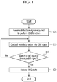
- FIG. 1 is a flowchart illustrating a method for controlling a vehicle including an idle stop and go (ISG) function in an exemplary form of the present disclosure.
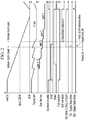
- FIG. 2 is a view explaining the method for controlling the vehicle including the ISG function shown in FIG. 1 .
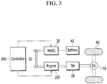
- FIG. 3 is a block diagram illustrating an example of a vehicle to which the method for controlling the vehicle including the ISG function shown in FIG. 1 is applied.
- a controller 200 may receive a detection signal desired for performing the ISG function.
- the ISG function may mean a function that stops an engine 205 of the vehicle to inhibit or prevent the engine from operating when the vehicle decelerates or stops and drives the engine again to enable the vehicle to move when the vehicle starts. More specifically, the ISG function may automatically stop the engine 205 by preventing fuel injection into the engine when the vehicle decelerates or stops while the vehicle is running and automatically restart the engine by a starter-generator 30 when the vehicle is no longer in the decelerated or stopped state (e.g., when the driver of the vehicle releases a brake pedal and depresses an acceleration pedal).
- the detection signal may include a fuel cut off signal that is in an on state when the vehicle is decelerated, is in an off state when revolutions per minute, namely RPM (or a revolution speed), of the engine 205 becomes a reference RPM of the engine.
- the detection signal may indicate whether a fuel supply to the engine is cut off, and also includes: a gear engagement signal indicating whether a gear of a transmission 20 of the vehicle is engaged, and a brake pedal signal indicating whether the brake pedal of the vehicle is operated.
- the reference RPM of the engine 205 may be greater than an idle RPM of the engine and may have a value (e.g., 1000 RPM) close to the idle RPM for maintaining the idle RPM and inhibiting or preventing the engine from turning off.
- the gear of the transmission 20 may be in an engagement state when the fuel cut off signal is in an on state.
- the engagement state of the gear of the transmission 20 may mean a state where a damper clutch of a torque converter of an automatic transmission is engaged.
- the fuel cut off signal may be used to improve fuel efficiency or fuel economy of the vehicle, to maintain the idle RPM of the engine 205, and to inhibit the engine from being turned off, when the vehicle decelerates.
- the fuel cut off signal may be generated by the controller 200 when the acceleration pedal of the vehicle is in an off state and the brake pedal is in an off state or the brake pedal is in an on state.
- an RPM of the engine 205 may be equal to or greater than a certain value (e.g., 1500 RPM or 2000 RPM).
- the reference RPM of the engine 205 may be detected by a RPM sensor of the vehicle and the detected RPM may be provided to the controller 200.
- the gear engagement signal may be detected by a sensor that senses gear engagement installed in the vehicle and the detected signal may be provided to the controller 200.
- the brake pedal signal may be detected by a brake pedal sensor (BPS) of the vehicle and the detected signal may be provided to the controller 200.
- a state of the acceleration pedal may be detected by an acceleration pedal position sensor (APS) of the vehicle and the detected signal may be provided to the controller 200.
- the controller 200 may control an overall operation of the vehicle.
- the controller 200 such as an engine control unit (ECU) may be one or more microprocessors operated by a program or hardware including the microprocessor.
- the program may include a series of commands for executing the method for controlling the vehicle including the idle stop and go function according to the exemplary form of the present disclosure.
- the commands may be stored in a memory.
- the vehicle may be, for example, a mild hybrid vehicle, and may include the engine 205, the transmission 20 such as the automatic transmission or a dual clutch transmission (DCT), the starter-generator (or the mild hybrid starter and generator) 30, a battery 40, a differential gear device 50, wheels 60, and the controller 200.
- the exemplary form of the present disclosure may be applied to a vehicle other than the mild hybrid vehicle shown in FIG. 3 .
- a device for controlling the vehicle including the Idle Stop and Go (ISG) function may include the starter-generator 30 and the controller 200.
- the engine 205 may convert chemical energy to mechanical energy by burning fuel and air. Torque of the engine 205 may be transmitted to an input shaft of the transmission 20, and torque output from an output shaft of the transmission may be transmitted to an axle of the vehicle via the differential gear device 50. The axle may rotate the wheels 60 so that the mild hybrid vehicle may be driven.
- the starter-generator 30 may convert electrical energy to mechanical energy or mechanical energy to electrical energy. In other words, the starter-generator 30 may start the engine 205 or generate electricity according to an output of the engine 205. In addition, the starter-generator 30 may assist the torque of the engine 205.
- the mild hybrid vehicle may use the torque of the starter-generator 30 as an auxiliary power while combustion torque of the engine 205 is a main power.
- the engine 205 and the starter-generator 30 may be connected via the belt 32 (or a pulley and a belt).
- the starter-generator 30 may be a part performing functions of an alternator, the engine torque assist, or regenerative braking.
- the starter-generator 30 may drive the engine 205 of the vehicle in a cranking and torque control mode of the vehicle (or the engine) and may generate electricity according to an output of the engine to charge the 48 V battery 40 in an electricity generation mode of the vehicle.
- the starter-generator 30 may operate in an operating mode in accordance with a driving state of the vehicle.
- the operating mode may include an engine starting mode, an engine torque assist mode for assisting torque of the engine by operating as a motor, a mode for charging the 48 V battery charging the 12 V battery that is connected to the 48 V battery via the LDC, a regenerative braking mode for charging the 48 V battery, or an inertial driving mode for extending a mileage of the vehicle.
- the starter-generator 30 may be optimally controlled according to the driving state of the vehicle to increase fuel efficiency of the vehicle.
- the battery 40 may supply electricity to the starter-generator 30 or may be charged by electricity collected through the starter-generator 30 in a regenerative braking mode of the vehicle.
- the battery 40 may be a 48 V battery.
- the mild hybrid vehicle may further include a low voltage DC-DC converter (LDC) that converts voltage supplied from the battery 40 to a low voltage and a 12 V battery that supplies the low voltage to an electric load of the vehicle.
- LDC low voltage DC-DC converter
- the controller 200 may control the vehicle to enter into an idle stop and go (ISG) state where a fuel supply to the engine 205 of the vehicle is cut off and the engine stops when the vehicle decelerates or stops according to the ISG function of the controller.
- the controller 200 may generate an idle stop and go (ISG) entry signal based on the fuel cut off signal "F/cut" that is in a state before transitioning from an on state to an off state, the gear engagement signal that is in an on state, and the brake pedal signal that is in an on state, and may enter the vehicle into the idle stop and go (ISG) state based on the idle stop and go (ISG) entry signal.
- An RPM of the engine 205 corresponding to the ISG entry signal may be greater than the reference revolution number of the engine and may be, for example, 1050 RPM.
- the ISG entry signal may be a signal that shuts down the engine 205 when the vehicle does not require acceleration.
- An engine stop order signal in FIG. 2 may the ISG entry signal.
- a fuel injection into the engine may be prohibited when the engine stop order signal may be in an on state.
- the ISG state may be released so that a fuel injection into the engine 205 is performed and the engine is restarted by a starter motor (or the starter-generator 30).
- an RPM of the engine 205 may be maintained at an RPM greater than or equal to the idle RPM when the vehicle decelerates and a gear shift stage may be lowered to, for example, a fifth stage, a fourth stage, or a third three stage to improve the vehicle driving performance when the vehicle decelerates again. Accordingly, the RPM of the engine may decrease in accordance with a speed of the vehicle during deceleration of the vehicle and may increase during shifting.
- the vehicle When the fuel cut off signal F/cut is in an on state, the gear engagement signal is in an on state, and the brake pedal signal is in an on state, the vehicle may perform a coasting drive.
- An acceleration pedal signal indicating whether the acceleration pedal of the vehicle is operated may be in an off state before the coasting drive of the vehicle.
- the acceleration pedal signal may be detected by the acceleration pedal position sensor (APS) of the vehicle and the detected signal may be provided to the controller 200.
- the vehicle speed (or the vehicle speed for fuel supply) corresponding to the reference RPM of the engine 205 may be, for example, 22 KPH.
- An operation time period of an electric oil pump (EOP) for operating the transmission 20 may be reduced when the vehicle speed for fuel supply is lowered.
- the gear included in the transmission 20 may be in a neutral state when the gear engagement signal is in an off state.
- the controller 200 may determine whether the brake pedal signal is switched from the on state to an off state.
- the controller 200 may release the ISG state when the brake pedal signal is switched from the on state to the off state in the determination step 115.
- the controller 200 may start the engine 205 of the vehicle by driving the starter-generator 30 in response to the acceleration pedal operation after the ISG state is released.
- the components, " ⁇ unit", block, or module which are used in the present exemplary form may be implemented in software such as a task, a class, a subroutine, a process, an object, an execution thread, or a program which is performed in a predetermined region in the memory, or hardware such as a field programmable gate array (FPGA) or an application-specific integrated circuit (ASIC), and may be performed with a combination of the software and the hardware.
- the components, ' ⁇ part', or the like may be embedded in a computer-readable storage medium, and some part thereof may be dispersedly distributed in a plurality of computers.
Abstract
Description
- This application claims priority to and the benefit of Korean Patent Application No.
10-2017-0174558, filed on December 18, 2017 - The present disclosure relates to a method for controlling a vehicle, and more particularly, to a method and a device for controlling a vehicle including an idle stop and go function.
- The statements in this section merely provide background information related to the present disclosure and may not constitute prior art.
- Efforts have been being made to reduce carbon dioxide generated by combustion of a fuel in a vehicle all over the world and to improve fuel efficiency of the vehicle as oil prices increase.
- An idle stop and go (ISG) system has been developed to meet the efforts. It has been proven that the ISG system can reduce an amount of carbon dioxide generated in the vehicle and can improve fuel efficiency.
- The ISG system is an engine control system that stops an engine of the vehicle to inhibit or prevent the engine from operating when the vehicle decelerates or stops and drives the engine again to enable the vehicle to move when the vehicle starts.
- The ISG system uses information such as the vehicle speed, the engine speed, and the engine coolant temperature to stop the engine when the engine is idling. In other words, the ISG system automatically stops the engine idling when the vehicle decelerates or stops due to a traffic signal and restarts the engine to start the vehicle after a predetermined time. The ISG system may also be named as an idling stop control device. The ISG system can achieve fuel economy of about 5 to 15% in a fuel economy mode. The vehicle equipped with the ISG system is referred to as an ISG vehicle.
- Because the ISG system inhibits or prevents the engine from operating when the vehicle decelerates or stops, the fuel cannot be used. Thus, the fuel efficiency of the vehicle can be improved and the carbon dioxide is less discharged.
- The ISG system includes a method of starting the engine using an electric motor and a method of starting the engine using a hydraulic motor. A passenger car can use the method of starting the engine using the electric motor.
- The above information disclosed in this Background section is only for enhancement of understanding of the background of the present disclosure, and therefore it may contain information that does not form the prior art that is already known to a person of ordinary skill in the art.
- The present disclosure provides a method and a device for controlling a vehicle including an idle stop and go function which are capable of maintaining a fuel cut off state until the vehicle stops after cutting off a fuel supply to an engine when the vehicle decelerates.
- In an exemplary form of the present disclosure, a method for controlling the vehicle having the idle stop and go function may include: receiving, by a controller, a detection signal to perform the idle stop and go function; and controlling, by the controller, the vehicle to enter into an idle stop and go state where a fuel supply to an engine of the vehicle is cut off and the engine stops when the vehicle decelerates or stops according to the idle stop and go function, in response to the detection signal. The detection signal may include a fuel cut off signal, a gear engagement signal, and a brake pedal signal. The fuel cut off signal is in an on state when the vehicle decelerates, is in an off state at a reference revolutions per minute (RPM) of the engine. The fuel cut off signal indicates whether a fuel supply to the engine is cut off, the gear engagement signal indicates whether a gear included in a transmission of the vehicle is engaged, and the brake pedal signal indicates whether the brake pedal of the vehicle is operated.
- The controller may be configured to generate an idle stop and go entry signal based on the fuel cut off signal that is in a state before transitioning from an on state to an off state, the gear engagement signal that is in an on state, and the brake pedal signal that is in an on state, and the controller is configured to enter the vehicle into the idle stop and go state based on the idle stop and go entry signal.
- The reference RPM of the engine may be greater than an idle RPM of the engine and may have a value close to the idle RPM.
- The gear of the transmission may be in an engagement state when the fuel cut off signal is in the on state.
- The method for controlling the vehicle including the idle stop and go function may further include: determining, by the controller, whether the brake pedal signal is switched from the on state to an off state. The controller may be configured to release the idle stop and go state when the brake pedal signal is switched to the off state
- The transmission may include an automatic transmission.
- Another exemplary form of the present disclosure may provide the device for controlling the vehicle including the idle stop and go function, the device may include: a starter-generator configured to drive an engine of the vehicle; and a controller configured to receive a detection signal to perform the idle stop and go function. The controller may be configured to control the vehicle to enter into an idle stop and go state in response to the detection signal where a fuel supply to the engine of the vehicle is cut off and the engine stops when the vehicle decelerates or stops according to the idle stop and go function, , and the controller is configured to operate the starter-generator when the idle stop and go state is released. The detection signal may include a fuel cut off signal, a gear engagement signal, and a brake pedal signal. The fuel cut off signal, which is in an on state when the vehicle decelerates, is in an off state at a reference revolution number of the engine (e.g., a reference revolutions per minute (RPM)), indicates whether a fuel supply to the engine is cut off. The gear engagement signal indicates whether a gear included in a transmission of the vehicle is engaged, and the brake pedal signal indicates whether the brake pedal of the vehicle is operated. The controller may be configured to generate an idle stop and go entry signal based on the fuel cut off signal that is in a state before transitioning from an on state to an off state, the gear engagement signal that is in an on state, and the brake pedal signal that is in an on state, and is configured to enter the vehicle into the idle stop and go state based on the idle stop and go entry signal.
- The reference RPM of the engine may be greater than an idle RPM of the engine and may have a value close to the idle revolutions per minute.
- The gear of the transmission may be in an engagement state when the fuel cut off signal is in an on state.
- The controller may be configured to determine whether the brake pedal signal is switched from the on state to an off state and may be configured to release the idle stop and go state when the brake pedal signal is switched to the off state.
- The method and the device for controlling the vehicle including the idle stop and go function according to the exemplary form of the present disclosure may enter the vehicle into the idle stop and go (ISG) state based on the idle stop and go (ISG) entry signal that is activated after the brake pedal is depressed in a state where the gear of the transmission is engaged after fuel cut by deceleration of the vehicle. Therefore, deterioration of the vehicle operability may be avoided or prevented even though a fuel injection into the engine is prohibited in an idle state of the engine due to entry of the ISG state. The deterioration of the vehicle operability may include deterioration of deceleration feeling of the vehicle driver that occurs due to increase of the engine friction torque caused by the fuel injection prohibition.
- Further areas of applicability will become apparent from the description provided herein. It should be understood that the description and specific examples are intended for purposes of illustration only and are not intended to limit the scope of the present disclosure.
- In order that the disclosure may be well understood, there will now be described various forms thereof, given by way of example, reference being made to the accompanying drawings, in which:
-
FIG. 1 is a flowchart illustrating a method for controlling a vehicle including an idle stop and go (ISG) function; -
FIG. 2 is a view explaining the method for controlling the vehicle including the ISGfunction shown inFIG. 1 ; and -
FIG. 3 is a block diagram illustrating an example of a vehicle to which the method for controlling the vehicle including the ISG function shown inFIG. 1 is applied. - The drawings described herein are for illustration purposes only and are not intended to limit the scope of the present disclosure in any way.
- The following description is merely exemplary in nature and is not intended to limit the present disclosure, application, or uses. It should be understood that throughout the drawings, corresponding reference numerals indicate like or corresponding parts and features.
- In describing the present disclosure, well-known configurations or functions will not be described in detail since they may unnecessarily obscure the gist of the present disclosure. Throughout the accompanying drawings, the same reference numerals will be used to denote the same components.
- Terms used in the present specification are only used in order to describe specific exemplary forms rather than limiting the present disclosure. Singular forms are to include plural forms unless the context clearly indicates otherwise. It will be further understood that the terms "include" or "have" used in the present specification specify the presence of features, numerals, steps, operations, components, or parts mentioned in the present specification, or a combination thereof, but do not preclude the presence or addition of one or more other features, numerals, steps, operations, components, parts, or a combination thereof.
- Throughout this specification and the claims that follow, when it is described that an element is "coupled" to another element, the element may be "directly coupled" to the other element or "electrically or mechanically coupled" to the other element through a third element.
- Unless defined otherwise, it is to be understood that the terms used in the present specification including technical and scientific terms have the same meanings as those that are generally understood by those skilled in the art. It must be understood that the terms defined by the dictionary are identical with the meanings within the context of the related art, and they should not be ideally or excessively formally defined unless the context clearly dictates otherwise.
- According to a related art, when a fuel cut signal for cutting off a fuel supplied to an engine is in an off state at a time of deceleration of a vehicle, the vehicle may enter into an idle stop & go (ISG) state only by depressing a brake pedal. Therefore, a fuel injection into the engine may be inhibited in an idle state of the engine by entry of the ISG state. As a result, an increase in the engine friction torque due to the fuel injection prohibition may result in deterioration of the vehicle driving performance such as deterioration of deceleration feeling of the vehicle driver.
-
FIG. 1 is a flowchart illustrating a method for controlling a vehicle including an idle stop and go (ISG) function in an exemplary form of the present disclosure.FIG. 2 is a view explaining the method for controlling the vehicle including the ISG function shown inFIG. 1 .FIG. 3 is a block diagram illustrating an example of a vehicle to which the method for controlling the vehicle including the ISG function shown inFIG. 1 is applied. - Referring to
FIG. 1 to FIG. 3 , in areception step 105, acontroller 200 may receive a detection signal desired for performing the ISG function. The ISG function may mean a function that stops anengine 205 of the vehicle to inhibit or prevent the engine from operating when the vehicle decelerates or stops and drives the engine again to enable the vehicle to move when the vehicle starts. More specifically, the ISG function may automatically stop theengine 205 by preventing fuel injection into the engine when the vehicle decelerates or stops while the vehicle is running and automatically restart the engine by a starter-generator 30 when the vehicle is no longer in the decelerated or stopped state (e.g., when the driver of the vehicle releases a brake pedal and depresses an acceleration pedal). - The detection signal may include a fuel cut off signal that is in an on state when the vehicle is decelerated, is in an off state when revolutions per minute, namely RPM (or a revolution speed), of the
engine 205 becomes a reference RPM of the engine. The detection signal may indicate whether a fuel supply to the engine is cut off, and also includes: a gear engagement signal indicating whether a gear of atransmission 20 of the vehicle is engaged, and a brake pedal signal indicating whether the brake pedal of the vehicle is operated. The reference RPM of theengine 205 may be greater than an idle RPM of the engine and may have a value (e.g., 1000 RPM) close to the idle RPM for maintaining the idle RPM and inhibiting or preventing the engine from turning off. The gear of thetransmission 20 may be in an engagement state when the fuel cut off signal is in an on state. For example, the engagement state of the gear of thetransmission 20 may mean a state where a damper clutch of a torque converter of an automatic transmission is engaged. - The fuel cut off signal may be used to improve fuel efficiency or fuel economy of the vehicle, to maintain the idle RPM of the
engine 205, and to inhibit the engine from being turned off, when the vehicle decelerates. The fuel cut off signal may be generated by thecontroller 200 when the acceleration pedal of the vehicle is in an off state and the brake pedal is in an off state or the brake pedal is in an on state. When the fuel cut off signal is in an on state, an RPM of theengine 205 may be equal to or greater than a certain value (e.g., 1500 RPM or 2000 RPM). - The reference RPM of the
engine 205 may be detected by a RPM sensor of the vehicle and the detected RPM may be provided to thecontroller 200. The gear engagement signal may be detected by a sensor that senses gear engagement installed in the vehicle and the detected signal may be provided to thecontroller 200. The brake pedal signal may be detected by a brake pedal sensor (BPS) of the vehicle and the detected signal may be provided to thecontroller 200. A state of the acceleration pedal may be detected by an acceleration pedal position sensor (APS) of the vehicle and the detected signal may be provided to thecontroller 200. - The
controller 200 may control an overall operation of the vehicle. For example, thecontroller 200 such as an engine control unit (ECU) may be one or more microprocessors operated by a program or hardware including the microprocessor. The program may include a series of commands for executing the method for controlling the vehicle including the idle stop and go function according to the exemplary form of the present disclosure. The commands may be stored in a memory. - The vehicle may be, for example, a mild hybrid vehicle, and may include the
engine 205, thetransmission 20 such as the automatic transmission or a dual clutch transmission (DCT), the starter-generator (or the mild hybrid starter and generator) 30, abattery 40, adifferential gear device 50,wheels 60, and thecontroller 200. The exemplary form of the present disclosure may be applied to a vehicle other than the mild hybrid vehicle shown inFIG. 3 . - A device for controlling the vehicle including the Idle Stop and Go (ISG) function may include the starter-
generator 30 and thecontroller 200. - The
engine 205 may convert chemical energy to mechanical energy by burning fuel and air. Torque of theengine 205 may be transmitted to an input shaft of thetransmission 20, and torque output from an output shaft of the transmission may be transmitted to an axle of the vehicle via thedifferential gear device 50. The axle may rotate thewheels 60 so that the mild hybrid vehicle may be driven. - The starter-
generator 30 may convert electrical energy to mechanical energy or mechanical energy to electrical energy. In other words, the starter-generator 30 may start theengine 205 or generate electricity according to an output of theengine 205. In addition, the starter-generator 30 may assist the torque of theengine 205. The mild hybrid vehicle may use the torque of the starter-generator 30 as an auxiliary power while combustion torque of theengine 205 is a main power. Theengine 205 and the starter-generator 30 may be connected via the belt 32 (or a pulley and a belt). - In the mild hybrid vehicle, the starter-
generator 30 may be a part performing functions of an alternator, the engine torque assist, or regenerative braking. - The starter-
generator 30 may drive theengine 205 of the vehicle in a cranking and torque control mode of the vehicle (or the engine) and may generate electricity according to an output of the engine to charge the 48V battery 40 in an electricity generation mode of the vehicle. The starter-generator 30 may operate in an operating mode in accordance with a driving state of the vehicle. The operating mode may include an engine starting mode, an engine torque assist mode for assisting torque of the engine by operating as a motor, a mode for charging the 48 V battery charging the 12 V battery that is connected to the 48 V battery via the LDC, a regenerative braking mode for charging the 48 V battery, or an inertial driving mode for extending a mileage of the vehicle. The starter-generator 30 may be optimally controlled according to the driving state of the vehicle to increase fuel efficiency of the vehicle. - The
battery 40 may supply electricity to the starter-generator 30 or may be charged by electricity collected through the starter-generator 30 in a regenerative braking mode of the vehicle. Thebattery 40 may be a 48 V battery. The mild hybrid vehicle may further include a low voltage DC-DC converter (LDC) that converts voltage supplied from thebattery 40 to a low voltage and a 12 V battery that supplies the low voltage to an electric load of the vehicle. - According to a
step 110, in response to the detection signal, thecontroller 200 may control the vehicle to enter into an idle stop and go (ISG) state where a fuel supply to theengine 205 of the vehicle is cut off and the engine stops when the vehicle decelerates or stops according to the ISG function of the controller. As shown inFIG. 2 , thecontroller 200 may generate an idle stop and go (ISG) entry signal based on the fuel cut off signal "F/cut" that is in a state before transitioning from an on state to an off state, the gear engagement signal that is in an on state, and the brake pedal signal that is in an on state, and may enter the vehicle into the idle stop and go (ISG) state based on the idle stop and go (ISG) entry signal. An RPM of theengine 205 corresponding to the ISG entry signal may be greater than the reference revolution number of the engine and may be, for example, 1050 RPM. The ISG entry signal may be a signal that shuts down theengine 205 when the vehicle does not require acceleration. - An engine stop order signal in
FIG. 2 may the ISG entry signal. A fuel injection into the engine may be prohibited when the engine stop order signal may be in an on state. When an engine start order signal is in an on state, the ISG state may be released so that a fuel injection into theengine 205 is performed and the engine is restarted by a starter motor (or the starter-generator 30). In the vehicle including the automatic transmission or the DCT, an RPM of theengine 205 may be maintained at an RPM greater than or equal to the idle RPM when the vehicle decelerates and a gear shift stage may be lowered to, for example, a fifth stage, a fourth stage, or a third three stage to improve the vehicle driving performance when the vehicle decelerates again. Accordingly, the RPM of the engine may decrease in accordance with a speed of the vehicle during deceleration of the vehicle and may increase during shifting. - When the fuel cut off signal F/cut is in an on state, the gear engagement signal is in an on state, and the brake pedal signal is in an on state, the vehicle may perform a coasting drive. An acceleration pedal signal indicating whether the acceleration pedal of the vehicle is operated may be in an off state before the coasting drive of the vehicle. The acceleration pedal signal may be detected by the acceleration pedal position sensor (APS) of the vehicle and the detected signal may be provided to the
controller 200. - The vehicle speed (or the vehicle speed for fuel supply) corresponding to the reference RPM of the
engine 205 may be, for example, 22 KPH. An operation time period of an electric oil pump (EOP) for operating thetransmission 20 may be reduced when the vehicle speed for fuel supply is lowered. The gear included in thetransmission 20 may be in a neutral state when the gear engagement signal is in an off state. - According to a
determination step 115, thecontroller 200 may determine whether the brake pedal signal is switched from the on state to an off state. - According to a
release step 120, thecontroller 200 may release the ISG state when the brake pedal signal is switched from the on state to the off state in thedetermination step 115. - The
controller 200 may start theengine 205 of the vehicle by driving the starter-generator 30 in response to the acceleration pedal operation after the ISG state is released. - The components, "∼ unit", block, or module which are used in the present exemplary form may be implemented in software such as a task, a class, a subroutine, a process, an object, an execution thread, or a program which is performed in a predetermined region in the memory, or hardware such as a field programmable gate array (FPGA) or an application-specific integrated circuit (ASIC), and may be performed with a combination of the software and the hardware. The components, '∼ part', or the like may be embedded in a computer-readable storage medium, and some part thereof may be dispersedly distributed in a plurality of computers.
- As set forth above, exemplary forms have been disclosed in the accompanying drawings and the specification. Herein, specific terms have been used, but are just used for the purpose of describing the present disclosure and are not used for qualifying the meaning or limiting the scope of the present disclosure. Therefore, it will be understood by those skilled in the art that various modifications and equivalent exemplary forms are possible from the present disclosure.
-
- 30: MHSG
- 200: controller
- 205: engine
Claims (10)
- A method for controlling a vehicle including an idle stop and go function, comprising the steps of:receiving, by a controller, a detection signal to perform the idle stop and go function; andcontrolling, by the controller, the vehicle to enter into an idle stop and go state where a fuel supply to an engine of the vehicle is cut off and the engine stops when the vehicle decelerates or stops based on the idle stop and go function, in response to the detection signal,wherein the detection signal includes a fuel cut off signal, a gear engagement signal, and a brake pedal signal,wherein the fuel cut off signal is in an on state when the vehicle decelerates and is in an off state at a reference revolutions per minute (RPM) of the engine, and wherein the fuel cut off signal indicates whether the fuel supply to the engine is cut off, and wherein the gear engagement signal indicates whether a gear of a transmission of the vehicle is engaged, and wherein the brake pedal signal indicates whether a brake pedal of the vehicle is operated, andwherein the controller is configured to generate an idle stop and go entry signal based on the fuel cut off signal that is in a state before transitioning from an on state to an off state, the gear engagement signal that is in an on state, and the brake pedal signal that is in an on state, and the controller is configured to enter the vehicle into the idle stop and go state based on the idle stop and go entry signal.
- The method of claim 1, wherein the reference RPM of the engine is greater than an idle RPM of the engine.
- The method of claim 1 or 2, wherein the gear of the transmission is in an engagement state when the fuel cut off signal is in the on state.
- The method of any one of the preceding claims, further comprising:determining, by the controller, whether the brake pedal signal is switched from the on state to an off state,wherein the controller is configured to release the idle stop and go state when the brake pedal signal is switched to the off state.
- The method of any one of the preceding claims, wherein the transmission includes an automatic transmission.
- A device for controlling a vehicle including an idle stop and go function, comprising:a starter-generator configured to drive an engine of the vehicle; anda controller configured to receive a detection signal to perform the idle stop and go function,wherein the controller is configured to control the vehicle to enter into an idle stop and go state in response to the detection signal where a fuel supply to the engine is cut off and the engine stops when the vehicle decelerates or stops, and the controller is configured to operate the starter-generator when the idle stop and go state is released,wherein the detection signal includes a fuel cut off signal, a gear engagement signal, and a brake pedal signal,wherein the fuel cut off signal is in an on state when the vehicle decelerates, is in an off state at a reference revolutions per minute (RPM) of the engine, and wherein the fuel cut off signal indicates whether the fuel supply to the engine is cut off, and wherein the gear engagement signal indicates whether a gear of a transmission of the vehicle is engaged, and wherein a brake pedal signal indicates whether a brake pedal of the vehicle is operated, andwherein the controller is configured to generate an idle stop and go entry signal based on the fuel cut off signal that is in a state before transitioning from an on state to an off state, the gear engagement signal that is in an on state, and the brake pedal signal that is in an on state, and the controller is configured to enter the vehicle into the idle stop and go state based on the idle stop and go entry signal.
- The device of claim 6, wherein the reference RPM of the engine is greater than an idle RPM of the engine and has a value close to the idle RPM.
- The device of claim 6 or 7, wherein the gear of the transmission is in an engagement state when the fuel cut off signal is in the on state.
- The device of any one of claims 6 to 9, wherein the controller is configured to determine whether the brake pedal signal is switched from the on state to an off state, and
wherein the controller is configured to release the idle stop and go state when the brake pedal signal is switched to the off state. - A method for controlling a vehicle including an idle stop and go function, comprising the steps of:generating, by a controller, an idle stop and go entry signal based on a detection signal;wherein the detection signal includes a fuel cut off signal, a gear engagement signal, and a brake pedal signal,wherein the fuel cut off signal is in an on state when the vehicle decelerates and is in an off state at a reference revolutions per minute (RPM) of the engine, and wherein the fuel cut off signal indicates whether a fuel supply to the engine is cut off, and wherein the gear engagement signal indicates whether a gear of a transmission of the vehicle is engaged, and wherein the brake pedal signal indicates whether a brake pedal of the vehicle is operated, andwherein the controller is configured to generate the idle stop and go entry signal when the fuel cut off signal is in a state before transitioning from an on state to an off state based on the reference RPM of the engine, and when the gear engagement signal is in an on state, and when the brake pedal signal that is in an on state.
Applications Claiming Priority (1)
| Application Number | Priority Date | Filing Date | Title |
|---|---|---|---|
| KR1020170174558A KR20190073182A (en) | 2017-12-18 | 2017-12-18 | Method and device for controlling vehicle including idle stop and go function |
Publications (2)
| Publication Number | Publication Date |
|---|---|
| EP3499010A1 true EP3499010A1 (en) | 2019-06-19 |
| EP3499010B1 EP3499010B1 (en) | 2020-11-25 |
Family
ID=62904326
Family Applications (1)
| Application Number | Title | Priority Date | Filing Date |
|---|---|---|---|
| EP18182393.1A Active EP3499010B1 (en) | 2017-12-18 | 2018-07-09 | Method and device for controlling vehicle including idle stop and go function |
Country Status (5)
| Country | Link |
|---|---|
| US (1) | US10920731B2 (en) |
| EP (1) | EP3499010B1 (en) |
| KR (1) | KR20190073182A (en) |
| CN (1) | CN109941284B (en) |
| ES (1) | ES2840230T3 (en) |
Families Citing this family (3)
| Publication number | Priority date | Publication date | Assignee | Title |
|---|---|---|---|---|
| KR20200046156A (en) * | 2018-10-16 | 2020-05-07 | 주식회사 만도 | Vehicle control system and vehicle control method |
| KR20210014254A (en) * | 2019-07-29 | 2021-02-09 | 현대자동차주식회사 | System for controlling automatically shut-off of a vehicle and method thereof |
| KR20210033151A (en) | 2019-09-18 | 2021-03-26 | 현대자동차주식회사 | Electronic device reset prevention control device of vehicle |
Citations (6)
| Publication number | Priority date | Publication date | Assignee | Title |
|---|---|---|---|---|
| DE19911736A1 (en) * | 1998-03-17 | 1999-09-23 | Honda Motor Co Ltd | Engine stop control system for vehicle with automatic transmission |
| DE102010034554A1 (en) * | 2009-09-01 | 2011-03-03 | Ford Global Technologies, LLC, Dearborn | System and method for restarting a motor |
| EP2789833A1 (en) * | 2011-12-06 | 2014-10-15 | Nissan Motor Co., Ltd | Automatic vehicle-engine control device |
| EP2789834A1 (en) * | 2011-12-06 | 2014-10-15 | Nissan Motor Co., Ltd | Automatic vehicle-engine control device |
| US20150158480A1 (en) * | 2013-12-05 | 2015-06-11 | Ford Global Technologies, Llc | System and method for controlling a stop/start system for a vehicle engine |
| US20150167614A1 (en) * | 2013-12-17 | 2015-06-18 | Ford Global Technologies, Llc | Vehicle and method of controlling an engine auto-stop and restart |
Family Cites Families (10)
| Publication number | Priority date | Publication date | Assignee | Title |
|---|---|---|---|---|
| JP3706732B2 (en) * | 1998-03-17 | 2005-10-19 | 本田技研工業株式会社 | Vehicle engine stop control device |
| KR100867798B1 (en) | 2006-10-18 | 2008-11-10 | 현대자동차주식회사 | Method for controling fuel rewet of hybrid car |
| JP2010229882A (en) * | 2009-03-27 | 2010-10-14 | Hitachi Automotive Systems Ltd | Vehicle control device and idling stop system |
| KR101189412B1 (en) * | 2010-12-07 | 2012-10-10 | 현대자동차주식회사 | Method and Device for Controlling ISG Logic |
| US9415771B1 (en) * | 2012-11-16 | 2016-08-16 | Nissan Motor Co., Ltd. | Control device for a hybrid vehicle |
| JP6094892B2 (en) * | 2013-10-16 | 2017-03-15 | 本田技研工業株式会社 | Vehicle control device |
| CN103802836B (en) * | 2014-01-26 | 2016-08-17 | 上汽通用五菱汽车股份有限公司 | A kind of method for controlling hybrid power vehicle |
| KR101576371B1 (en) | 2014-06-11 | 2015-12-10 | 고성석 | Intelligent idle stop and go control device and method thereof |
| JP6319148B2 (en) * | 2015-03-17 | 2018-05-09 | トヨタ自動車株式会社 | Control device for multi-cylinder internal combustion engine |
| KR20190072926A (en) * | 2017-12-18 | 2019-06-26 | 현대자동차주식회사 | Method for controlling vehicle including idle stop and go function |
-
2017
- 2017-12-18 KR KR1020170174558A patent/KR20190073182A/en not_active Application Discontinuation
-
2018
- 2018-06-19 US US16/012,075 patent/US10920731B2/en active Active
- 2018-07-09 EP EP18182393.1A patent/EP3499010B1/en active Active
- 2018-07-09 ES ES18182393T patent/ES2840230T3/en active Active
- 2018-07-25 CN CN201810825349.7A patent/CN109941284B/en active Active
Patent Citations (6)
| Publication number | Priority date | Publication date | Assignee | Title |
|---|---|---|---|---|
| DE19911736A1 (en) * | 1998-03-17 | 1999-09-23 | Honda Motor Co Ltd | Engine stop control system for vehicle with automatic transmission |
| DE102010034554A1 (en) * | 2009-09-01 | 2011-03-03 | Ford Global Technologies, LLC, Dearborn | System and method for restarting a motor |
| EP2789833A1 (en) * | 2011-12-06 | 2014-10-15 | Nissan Motor Co., Ltd | Automatic vehicle-engine control device |
| EP2789834A1 (en) * | 2011-12-06 | 2014-10-15 | Nissan Motor Co., Ltd | Automatic vehicle-engine control device |
| US20150158480A1 (en) * | 2013-12-05 | 2015-06-11 | Ford Global Technologies, Llc | System and method for controlling a stop/start system for a vehicle engine |
| US20150167614A1 (en) * | 2013-12-17 | 2015-06-18 | Ford Global Technologies, Llc | Vehicle and method of controlling an engine auto-stop and restart |
Also Published As
| Publication number | Publication date |
|---|---|
| EP3499010B1 (en) | 2020-11-25 |
| KR20190073182A (en) | 2019-06-26 |
| CN109941284B (en) | 2023-06-30 |
| US10920731B2 (en) | 2021-02-16 |
| ES2840230T3 (en) | 2021-07-06 |
| CN109941284A (en) | 2019-06-28 |
| US20190186450A1 (en) | 2019-06-20 |
Similar Documents
| Publication | Publication Date | Title |
|---|---|---|
| US8042632B2 (en) | Creep mode propulsion for stop-start hybrid vehicles | |
| US9562480B2 (en) | Automatic engine-stop control device for vehicle | |
| JP5478572B2 (en) | Control device for hybrid vehicle | |
| WO2011145190A1 (en) | Vehicle control system | |
| JP2002155773A (en) | Vehicle driving device | |
| EP3179125A1 (en) | Vehicle control device, and vehicle control method | |
| US9586469B2 (en) | Hybrid vehicle control device | |
| JP2016211495A (en) | Restart control device for internal combustion engine | |
| US10920731B2 (en) | Method and device for controlling vehicle including idle stop and go function | |
| EP2669126A1 (en) | Vehicle, and vehicle control method | |
| US11028813B2 (en) | Method for controlling a vehicle including an idle stop and go function | |
| JP2014173454A (en) | Control device of idle stop vehicle | |
| JP2018167738A (en) | Vehicle control device | |
| US11377106B2 (en) | Control method for ISG of vehicle equipped with manual transmission | |
| US11125200B2 (en) | Control method for SSC and ISG of vehicle and vehicle to which the control method is applied | |
| US10640114B2 (en) | Method for controlling mild hybrid electric vehicle | |
| US11440526B2 (en) | Control method for SSC and ISG of vehicle and vehicle to which the control method is applied | |
| JP2005207311A (en) | Vehicle control system | |
| US11286897B2 (en) | Control method for ISG of vehicle provided with manual transmission and vehicle of which the control method is applied | |
| KR102451875B1 (en) | Method for controlling vehicle | |
| JP5941934B2 (en) | Vehicle control device | |
| JP2019001302A (en) | Device for controlling drive of vehicle | |
| JP2004257259A (en) | Hybrid automobile | |
| JP2023152138A (en) | Vehicle control device | |
| JP2017197115A (en) | On-vehicle system |
Legal Events
| Date | Code | Title | Description |
|---|---|---|---|
| PUAI | Public reference made under article 153(3) epc to a published international application that has entered the european phase |
Free format text: ORIGINAL CODE: 0009012 |
|
| STAA | Information on the status of an ep patent application or granted ep patent |
Free format text: STATUS: THE APPLICATION HAS BEEN PUBLISHED |
|
| STAA | Information on the status of an ep patent application or granted ep patent |
Free format text: STATUS: REQUEST FOR EXAMINATION WAS MADE |
|
| AK | Designated contracting states |
Kind code of ref document: A1 Designated state(s): AL AT BE BG CH CY CZ DE DK EE ES FI FR GB GR HR HU IE IS IT LI LT LU LV MC MK MT NL NO PL PT RO RS SE SI SK SM TR |
|
| AX | Request for extension of the european patent |
Extension state: BA ME |
|
| 17P | Request for examination filed |
Effective date: 20190521 |
|
| RBV | Designated contracting states (corrected) |
Designated state(s): AL AT BE BG CH CY CZ DE DK EE ES FI FR GB GR HR HU IE IS IT LI LT LU LV MC MK MT NL NO PL PT RO RS SE SI SK SM TR |
|
| GRAP | Despatch of communication of intention to grant a patent |
Free format text: ORIGINAL CODE: EPIDOSNIGR1 |
|
| STAA | Information on the status of an ep patent application or granted ep patent |
Free format text: STATUS: GRANT OF PATENT IS INTENDED |
|
| INTG | Intention to grant announced |
Effective date: 20200619 |
|
| GRAS | Grant fee paid |
Free format text: ORIGINAL CODE: EPIDOSNIGR3 |
|
| GRAA | (expected) grant |
Free format text: ORIGINAL CODE: 0009210 |
|
| STAA | Information on the status of an ep patent application or granted ep patent |
Free format text: STATUS: THE PATENT HAS BEEN GRANTED |
|
| AK | Designated contracting states |
Kind code of ref document: B1 Designated state(s): AL AT BE BG CH CY CZ DE DK EE ES FI FR GB GR HR HU IE IS IT LI LT LU LV MC MK MT NL NO PL PT RO RS SE SI SK SM TR |
|
| REG | Reference to a national code |
Ref country code: GB Ref legal event code: FG4D |
|
| REG | Reference to a national code |
Ref country code: CH Ref legal event code: EP |
|
| REG | Reference to a national code |
Ref country code: AT Ref legal event code: REF Ref document number: 1338586 Country of ref document: AT Kind code of ref document: T Effective date: 20201215 |
|
| REG | Reference to a national code |
Ref country code: DE Ref legal event code: R096 Ref document number: 602018010031 Country of ref document: DE |
|
| REG | Reference to a national code |
Ref country code: IE Ref legal event code: FG4D |
|
| REG | Reference to a national code |
Ref country code: AT Ref legal event code: MK05 Ref document number: 1338586 Country of ref document: AT Kind code of ref document: T Effective date: 20201125 |
|
| REG | Reference to a national code |
Ref country code: NL Ref legal event code: MP Effective date: 20201125 |
|
| PG25 | Lapsed in a contracting state [announced via postgrant information from national office to epo] |
Ref country code: FI Free format text: LAPSE BECAUSE OF FAILURE TO SUBMIT A TRANSLATION OF THE DESCRIPTION OR TO PAY THE FEE WITHIN THE PRESCRIBED TIME-LIMIT Effective date: 20201125 Ref country code: PT Free format text: LAPSE BECAUSE OF FAILURE TO SUBMIT A TRANSLATION OF THE DESCRIPTION OR TO PAY THE FEE WITHIN THE PRESCRIBED TIME-LIMIT Effective date: 20210325 Ref country code: RS Free format text: LAPSE BECAUSE OF FAILURE TO SUBMIT A TRANSLATION OF THE DESCRIPTION OR TO PAY THE FEE WITHIN THE PRESCRIBED TIME-LIMIT Effective date: 20201125 Ref country code: NO Free format text: LAPSE BECAUSE OF FAILURE TO SUBMIT A TRANSLATION OF THE DESCRIPTION OR TO PAY THE FEE WITHIN THE PRESCRIBED TIME-LIMIT Effective date: 20210225 Ref country code: GR Free format text: LAPSE BECAUSE OF FAILURE TO SUBMIT A TRANSLATION OF THE DESCRIPTION OR TO PAY THE FEE WITHIN THE PRESCRIBED TIME-LIMIT Effective date: 20210226 |
|
| PG25 | Lapsed in a contracting state [announced via postgrant information from national office to epo] |
Ref country code: SE Free format text: LAPSE BECAUSE OF FAILURE TO SUBMIT A TRANSLATION OF THE DESCRIPTION OR TO PAY THE FEE WITHIN THE PRESCRIBED TIME-LIMIT Effective date: 20201125 Ref country code: LV Free format text: LAPSE BECAUSE OF FAILURE TO SUBMIT A TRANSLATION OF THE DESCRIPTION OR TO PAY THE FEE WITHIN THE PRESCRIBED TIME-LIMIT Effective date: 20201125 Ref country code: IS Free format text: LAPSE BECAUSE OF FAILURE TO SUBMIT A TRANSLATION OF THE DESCRIPTION OR TO PAY THE FEE WITHIN THE PRESCRIBED TIME-LIMIT Effective date: 20210325 Ref country code: PL Free format text: LAPSE BECAUSE OF FAILURE TO SUBMIT A TRANSLATION OF THE DESCRIPTION OR TO PAY THE FEE WITHIN THE PRESCRIBED TIME-LIMIT Effective date: 20201125 Ref country code: BG Free format text: LAPSE BECAUSE OF FAILURE TO SUBMIT A TRANSLATION OF THE DESCRIPTION OR TO PAY THE FEE WITHIN THE PRESCRIBED TIME-LIMIT Effective date: 20210225 Ref country code: AT Free format text: LAPSE BECAUSE OF FAILURE TO SUBMIT A TRANSLATION OF THE DESCRIPTION OR TO PAY THE FEE WITHIN THE PRESCRIBED TIME-LIMIT Effective date: 20201125 |
|
| REG | Reference to a national code |
Ref country code: LT Ref legal event code: MG9D |
|
| PG25 | Lapsed in a contracting state [announced via postgrant information from national office to epo] |
Ref country code: HR Free format text: LAPSE BECAUSE OF FAILURE TO SUBMIT A TRANSLATION OF THE DESCRIPTION OR TO PAY THE FEE WITHIN THE PRESCRIBED TIME-LIMIT Effective date: 20201125 |
|
| REG | Reference to a national code |
Ref country code: ES Ref legal event code: FG2A Ref document number: 2840230 Country of ref document: ES Kind code of ref document: T3 Effective date: 20210706 |
|
| PG25 | Lapsed in a contracting state [announced via postgrant information from national office to epo] |
Ref country code: LT Free format text: LAPSE BECAUSE OF FAILURE TO SUBMIT A TRANSLATION OF THE DESCRIPTION OR TO PAY THE FEE WITHIN THE PRESCRIBED TIME-LIMIT Effective date: 20201125 Ref country code: SK Free format text: LAPSE BECAUSE OF FAILURE TO SUBMIT A TRANSLATION OF THE DESCRIPTION OR TO PAY THE FEE WITHIN THE PRESCRIBED TIME-LIMIT Effective date: 20201125 Ref country code: RO Free format text: LAPSE BECAUSE OF FAILURE TO SUBMIT A TRANSLATION OF THE DESCRIPTION OR TO PAY THE FEE WITHIN THE PRESCRIBED TIME-LIMIT Effective date: 20201125 Ref country code: SM Free format text: LAPSE BECAUSE OF FAILURE TO SUBMIT A TRANSLATION OF THE DESCRIPTION OR TO PAY THE FEE WITHIN THE PRESCRIBED TIME-LIMIT Effective date: 20201125 Ref country code: CZ Free format text: LAPSE BECAUSE OF FAILURE TO SUBMIT A TRANSLATION OF THE DESCRIPTION OR TO PAY THE FEE WITHIN THE PRESCRIBED TIME-LIMIT Effective date: 20201125 Ref country code: EE Free format text: LAPSE BECAUSE OF FAILURE TO SUBMIT A TRANSLATION OF THE DESCRIPTION OR TO PAY THE FEE WITHIN THE PRESCRIBED TIME-LIMIT Effective date: 20201125 |
|
| REG | Reference to a national code |
Ref country code: DE Ref legal event code: R097 Ref document number: 602018010031 Country of ref document: DE |
|
| PG25 | Lapsed in a contracting state [announced via postgrant information from national office to epo] |
Ref country code: DK Free format text: LAPSE BECAUSE OF FAILURE TO SUBMIT A TRANSLATION OF THE DESCRIPTION OR TO PAY THE FEE WITHIN THE PRESCRIBED TIME-LIMIT Effective date: 20201125 |
|
| PLBE | No opposition filed within time limit |
Free format text: ORIGINAL CODE: 0009261 |
|
| STAA | Information on the status of an ep patent application or granted ep patent |
Free format text: STATUS: NO OPPOSITION FILED WITHIN TIME LIMIT |
|
| PG25 | Lapsed in a contracting state [announced via postgrant information from national office to epo] |
Ref country code: IT Free format text: LAPSE BECAUSE OF FAILURE TO SUBMIT A TRANSLATION OF THE DESCRIPTION OR TO PAY THE FEE WITHIN THE PRESCRIBED TIME-LIMIT Effective date: 20201125 Ref country code: AL Free format text: LAPSE BECAUSE OF FAILURE TO SUBMIT A TRANSLATION OF THE DESCRIPTION OR TO PAY THE FEE WITHIN THE PRESCRIBED TIME-LIMIT Effective date: 20201125 Ref country code: NL Free format text: LAPSE BECAUSE OF FAILURE TO SUBMIT A TRANSLATION OF THE DESCRIPTION OR TO PAY THE FEE WITHIN THE PRESCRIBED TIME-LIMIT Effective date: 20201125 |
|
| 26N | No opposition filed |
Effective date: 20210826 |
|
| PG25 | Lapsed in a contracting state [announced via postgrant information from national office to epo] |
Ref country code: SI Free format text: LAPSE BECAUSE OF FAILURE TO SUBMIT A TRANSLATION OF THE DESCRIPTION OR TO PAY THE FEE WITHIN THE PRESCRIBED TIME-LIMIT Effective date: 20201125 |
|
| REG | Reference to a national code |
Ref country code: CH Ref legal event code: PL |
|
| PG25 | Lapsed in a contracting state [announced via postgrant information from national office to epo] |
Ref country code: MC Free format text: LAPSE BECAUSE OF FAILURE TO SUBMIT A TRANSLATION OF THE DESCRIPTION OR TO PAY THE FEE WITHIN THE PRESCRIBED TIME-LIMIT Effective date: 20201125 |
|
| REG | Reference to a national code |
Ref country code: BE Ref legal event code: MM Effective date: 20210731 |
|
| PG25 | Lapsed in a contracting state [announced via postgrant information from national office to epo] |
Ref country code: LI Free format text: LAPSE BECAUSE OF NON-PAYMENT OF DUE FEES Effective date: 20210731 Ref country code: CH Free format text: LAPSE BECAUSE OF NON-PAYMENT OF DUE FEES Effective date: 20210731 |
|
| PG25 | Lapsed in a contracting state [announced via postgrant information from national office to epo] |
Ref country code: IS Free format text: LAPSE BECAUSE OF FAILURE TO SUBMIT A TRANSLATION OF THE DESCRIPTION OR TO PAY THE FEE WITHIN THE PRESCRIBED TIME-LIMIT Effective date: 20210325 Ref country code: LU Free format text: LAPSE BECAUSE OF NON-PAYMENT OF DUE FEES Effective date: 20210709 |
|
| PG25 | Lapsed in a contracting state [announced via postgrant information from national office to epo] |
Ref country code: IE Free format text: LAPSE BECAUSE OF NON-PAYMENT OF DUE FEES Effective date: 20210709 Ref country code: BE Free format text: LAPSE BECAUSE OF NON-PAYMENT OF DUE FEES Effective date: 20210731 |
|
| P01 | Opt-out of the competence of the unified patent court (upc) registered |
Effective date: 20230519 |
|
| PG25 | Lapsed in a contracting state [announced via postgrant information from national office to epo] |
Ref country code: CY Free format text: LAPSE BECAUSE OF FAILURE TO SUBMIT A TRANSLATION OF THE DESCRIPTION OR TO PAY THE FEE WITHIN THE PRESCRIBED TIME-LIMIT Effective date: 20201125 |
|
| PG25 | Lapsed in a contracting state [announced via postgrant information from national office to epo] |
Ref country code: HU Free format text: LAPSE BECAUSE OF FAILURE TO SUBMIT A TRANSLATION OF THE DESCRIPTION OR TO PAY THE FEE WITHIN THE PRESCRIBED TIME-LIMIT; INVALID AB INITIO Effective date: 20180709 |
|
| PGFP | Annual fee paid to national office [announced via postgrant information from national office to epo] |
Ref country code: FR Payment date: 20230621 Year of fee payment: 6 |
|
| PGFP | Annual fee paid to national office [announced via postgrant information from national office to epo] |
Ref country code: GB Payment date: 20230620 Year of fee payment: 6 Ref country code: ES Payment date: 20230814 Year of fee payment: 6 |
|
| PGFP | Annual fee paid to national office [announced via postgrant information from national office to epo] |
Ref country code: DE Payment date: 20230620 Year of fee payment: 6 |