EP3498984A1 - Seal retention assembly for gas turbine engine and corresponding method of assembly - Google Patents
Seal retention assembly for gas turbine engine and corresponding method of assembly Download PDFInfo
- Publication number
- EP3498984A1 EP3498984A1 EP18211987.5A EP18211987A EP3498984A1 EP 3498984 A1 EP3498984 A1 EP 3498984A1 EP 18211987 A EP18211987 A EP 18211987A EP 3498984 A1 EP3498984 A1 EP 3498984A1
- Authority
- EP
- European Patent Office
- Prior art keywords
- seal
- wall
- assembly
- gas turbine
- face seal
- Prior art date
- Legal status (The legal status is an assumption and is not a legal conclusion. Google has not performed a legal analysis and makes no representation as to the accuracy of the status listed.)
- Granted
Links
Images



Classifications
-
- F—MECHANICAL ENGINEERING; LIGHTING; HEATING; WEAPONS; BLASTING
- F01—MACHINES OR ENGINES IN GENERAL; ENGINE PLANTS IN GENERAL; STEAM ENGINES
- F01D—NON-POSITIVE DISPLACEMENT MACHINES OR ENGINES, e.g. STEAM TURBINES
- F01D11/00—Preventing or minimising internal leakage of working-fluid, e.g. between stages
- F01D11/003—Preventing or minimising internal leakage of working-fluid, e.g. between stages by packing rings; Mechanical seals
-
- F—MECHANICAL ENGINEERING; LIGHTING; HEATING; WEAPONS; BLASTING
- F02—COMBUSTION ENGINES; HOT-GAS OR COMBUSTION-PRODUCT ENGINE PLANTS
- F02C—GAS-TURBINE PLANTS; AIR INTAKES FOR JET-PROPULSION PLANTS; CONTROLLING FUEL SUPPLY IN AIR-BREATHING JET-PROPULSION PLANTS
- F02C7/00—Features, components parts, details or accessories, not provided for in, or of interest apart form groups F02C1/00 - F02C6/00; Air intakes for jet-propulsion plants
- F02C7/28—Arrangement of seals
-
- F—MECHANICAL ENGINEERING; LIGHTING; HEATING; WEAPONS; BLASTING
- F01—MACHINES OR ENGINES IN GENERAL; ENGINE PLANTS IN GENERAL; STEAM ENGINES
- F01D—NON-POSITIVE DISPLACEMENT MACHINES OR ENGINES, e.g. STEAM TURBINES
- F01D11/00—Preventing or minimising internal leakage of working-fluid, e.g. between stages
- F01D11/005—Sealing means between non relatively rotating elements
-
- F—MECHANICAL ENGINEERING; LIGHTING; HEATING; WEAPONS; BLASTING
- F01—MACHINES OR ENGINES IN GENERAL; ENGINE PLANTS IN GENERAL; STEAM ENGINES
- F01D—NON-POSITIVE DISPLACEMENT MACHINES OR ENGINES, e.g. STEAM TURBINES
- F01D25/00—Component parts, details, or accessories, not provided for in, or of interest apart from, other groups
- F01D25/16—Arrangement of bearings; Supporting or mounting bearings in casings
- F01D25/162—Bearing supports
-
- F—MECHANICAL ENGINEERING; LIGHTING; HEATING; WEAPONS; BLASTING
- F01—MACHINES OR ENGINES IN GENERAL; ENGINE PLANTS IN GENERAL; STEAM ENGINES
- F01D—NON-POSITIVE DISPLACEMENT MACHINES OR ENGINES, e.g. STEAM TURBINES
- F01D25/00—Component parts, details, or accessories, not provided for in, or of interest apart from, other groups
- F01D25/18—Lubricating arrangements
- F01D25/183—Sealing means
-
- F—MECHANICAL ENGINEERING; LIGHTING; HEATING; WEAPONS; BLASTING
- F02—COMBUSTION ENGINES; HOT-GAS OR COMBUSTION-PRODUCT ENGINE PLANTS
- F02C—GAS-TURBINE PLANTS; AIR INTAKES FOR JET-PROPULSION PLANTS; CONTROLLING FUEL SUPPLY IN AIR-BREATHING JET-PROPULSION PLANTS
- F02C3/00—Gas-turbine plants characterised by the use of combustion products as the working fluid
- F02C3/14—Gas-turbine plants characterised by the use of combustion products as the working fluid characterised by the arrangement of the combustion chamber in the plant
-
- F—MECHANICAL ENGINEERING; LIGHTING; HEATING; WEAPONS; BLASTING
- F02—COMBUSTION ENGINES; HOT-GAS OR COMBUSTION-PRODUCT ENGINE PLANTS
- F02C—GAS-TURBINE PLANTS; AIR INTAKES FOR JET-PROPULSION PLANTS; CONTROLLING FUEL SUPPLY IN AIR-BREATHING JET-PROPULSION PLANTS
- F02C7/00—Features, components parts, details or accessories, not provided for in, or of interest apart form groups F02C1/00 - F02C6/00; Air intakes for jet-propulsion plants
- F02C7/06—Arrangements of bearings; Lubricating
-
- F—MECHANICAL ENGINEERING; LIGHTING; HEATING; WEAPONS; BLASTING
- F16—ENGINEERING ELEMENTS AND UNITS; GENERAL MEASURES FOR PRODUCING AND MAINTAINING EFFECTIVE FUNCTIONING OF MACHINES OR INSTALLATIONS; THERMAL INSULATION IN GENERAL
- F16J—PISTONS; CYLINDERS; SEALINGS
- F16J15/00—Sealings
- F16J15/02—Sealings between relatively-stationary surfaces
- F16J15/06—Sealings between relatively-stationary surfaces with solid packing compressed between sealing surfaces
-
- F—MECHANICAL ENGINEERING; LIGHTING; HEATING; WEAPONS; BLASTING
- F05—INDEXING SCHEMES RELATING TO ENGINES OR PUMPS IN VARIOUS SUBCLASSES OF CLASSES F01-F04
- F05D—INDEXING SCHEME FOR ASPECTS RELATING TO NON-POSITIVE-DISPLACEMENT MACHINES OR ENGINES, GAS-TURBINES OR JET-PROPULSION PLANTS
- F05D2220/00—Application
- F05D2220/30—Application in turbines
- F05D2220/32—Application in turbines in gas turbines
-
- F—MECHANICAL ENGINEERING; LIGHTING; HEATING; WEAPONS; BLASTING
- F05—INDEXING SCHEMES RELATING TO ENGINES OR PUMPS IN VARIOUS SUBCLASSES OF CLASSES F01-F04
- F05D—INDEXING SCHEME FOR ASPECTS RELATING TO NON-POSITIVE-DISPLACEMENT MACHINES OR ENGINES, GAS-TURBINES OR JET-PROPULSION PLANTS
- F05D2230/00—Manufacture
- F05D2230/60—Assembly methods
-
- F—MECHANICAL ENGINEERING; LIGHTING; HEATING; WEAPONS; BLASTING
- F05—INDEXING SCHEMES RELATING TO ENGINES OR PUMPS IN VARIOUS SUBCLASSES OF CLASSES F01-F04
- F05D—INDEXING SCHEME FOR ASPECTS RELATING TO NON-POSITIVE-DISPLACEMENT MACHINES OR ENGINES, GAS-TURBINES OR JET-PROPULSION PLANTS
- F05D2240/00—Components
- F05D2240/55—Seals
-
- F—MECHANICAL ENGINEERING; LIGHTING; HEATING; WEAPONS; BLASTING
- F05—INDEXING SCHEMES RELATING TO ENGINES OR PUMPS IN VARIOUS SUBCLASSES OF CLASSES F01-F04
- F05D—INDEXING SCHEME FOR ASPECTS RELATING TO NON-POSITIVE-DISPLACEMENT MACHINES OR ENGINES, GAS-TURBINES OR JET-PROPULSION PLANTS
- F05D2260/00—Function
- F05D2260/30—Retaining components in desired mutual position
- F05D2260/36—Retaining components in desired mutual position by a form fit connection, e.g. by interlocking
Definitions
- Exemplary embodiments pertain to the art of gas turbine engines and, more particularly, to a seal retention assembly for a gas turbine engine.
- Advanced high performance engines such as those used in commercial jetliners, utilize main shaft bearing compartment seals to seal a main shaft bearing compartment and minimize lubricant from escaping the bearing compartment.
- Carbon seals are typically used for this purpose, and enable the engine and bearing compartment to function with minimal impact on the thrust specific fuel consumption, thermal management system, or the lubrication system.
- Face seal assemblies in gas turbine engines often include a seal retaining feature that is integral to a seal carrier, but this adds mass to the carrier and can make separation requirements difficult. A higher mass requires heavier springs, which in turn amplifies wear rate and heat generation resultants.
- the challenge is to design a carrier that is lightweight, but strong enough to withstand the stresses of the interference fit of the carbon and avoid bending due to the applied spring load, and meet the fit requirements with the surrounding hardware.
- the assembly includes a seal.
- the assembly also includes a seal carrier including a first seal wall, a second seal wall and a base seal wall, the first seal wall, the second seal wall and the base seal wall defining a groove for receiving the seal therein, the second seal wall extending radially outwardly to a non-uniform radial location.
- further embodiments may include that the second seal wall includes a plurality of segments extending to a common, first radial location and a plurality of recessed portions extending to a second radial location that is radially inward of the first radial location.
- each of the plurality of recessed portions extends circumferentially between an adjacent pair of the plurality of segments.
- further embodiments may include that the groove is substantially U-shaped.
- further embodiments may include that the face seal assembly is disposed in a gas turbine engine.
- further embodiments may include that the face seal assembly is located adjacent a bearing compartment disposed proximate a main shaft assembly of the gas turbine engine.
- further embodiments may include that the face seal assembly is located within the compressor section of the gas turbine engine.
- a gas turbine engine including a compressor section, a combustion section, a turbine section, a main shaft assembly, and a face seal assembly.
- the face seal assembly includes a seal.
- the face seal assembly also includes a seal carrier including a first seal wall, a second seal wall and a base seal wall, the first seal wall, the second seal wall and the base seal wall defining a groove for receiving the seal therein, the second seal wall extending radially outwardly to a non-uniform radial location.
- further embodiments may include that the second seal wall includes a plurality of segments extending to a common, first radial location and a plurality of recessed portions extending to a second radial location that is radially inward of the first radial location.
- each of the plurality of recessed portions extends circumferentially between an adjacent pair of the plurality of segments.
- further embodiments may include that the groove is substantially U-shaped.
- further embodiments may include that the face seal assembly is located adjacent a bearing compartment disposed proximate a main shaft of the gas turbine engine.
- further embodiments may include that the face seal assembly is located within the compressor section.
- the method includes disposing at least one seal segment within a groove defined by a first seal wall, a second seal wall and a seal base wall, the second seal wall extending radially outwardly to a non-uniform radial location.
- FIG. 1 schematically illustrates a gas turbine engine 20.
- the gas turbine engine 20 is disclosed herein as a two-spool turbofan that generally incorporates a fan section 22, a compressor section 24, a combustor section 26 and a turbine section 28.
- Alternative engines might include an augmentor section (not shown) among other systems or features.
- the fan section 22 drives air along a bypass flow path B in a bypass duct, while the compressor section 24 drives air along a core flow path C for compression and communication into the combustor section 26 then expansion through the turbine section 28.
- the exemplary engine 20 generally includes a low speed spool 30 and a high speed spool 32 mounted for rotation about an engine central longitudinal axis A relative to an engine static structure 36 via several bearing systems 38. It should be understood that various bearing systems 38 at various locations may alternatively or additionally be provided, and the location of bearing systems 38 may be varied as appropriate to the application.
- the low speed spool 30 generally includes an inner shaft 40 that interconnects a fan 42, a low pressure compressor 44 and a low pressure turbine 46.
- the inner shaft 40 is connected to the fan 42 through a speed change mechanism, which in exemplary gas turbine engine 20 is illustrated as a geared architecture 48 to drive the fan 42 at a lower speed than the low speed spool 30.
- the high speed spool 32 includes an outer shaft 50 that interconnects a high pressure compressor 52 and high pressure turbine 54.
- a combustor 56 is arranged in exemplary gas turbine 20 between the high pressure compressor 52 and the high pressure turbine 54.
- An engine static structure 36 is arranged generally between the high pressure turbine 54 and the low pressure turbine 46.
- the engine static structure 36 further supports bearing systems 38 in the turbine section 28.
- the inner shaft 40 and the outer shaft 50 are concentric and rotate via bearing systems 38 about the engine central longitudinal axis A which is collinear with their longitudinal axes.
- each of the positions of the fan section 22, compressor section 24, combustor section 26, turbine section 28, and fan drive gear system 48 may be varied.
- gear system 48 may be located aft of combustor section 26 or even aft of turbine section 28, and fan section 22 may be positioned forward or aft of the location of gear system 48.
- the engine 20 in one example is a high-bypass geared aircraft engine.
- the engine 20 bypass ratio is greater than about six (6), with an example embodiment being greater than about ten (10)
- the geared architecture 48 is an epicyclic gear train, such as a planetary gear system or other gear system, with a gear reduction ratio of greater than about 2.3 and the low pressure turbine 46 has a pressure ratio that is greater than about five.
- the engine 20 bypass ratio is greater than about ten (10:1)
- the fan diameter is significantly larger than that of the low pressure compressor 44
- the low pressure turbine 46 has a pressure ratio that is greater than about five (5:1).
- Low pressure turbine 46 pressure ratio is pressure measured prior to inlet of low pressure turbine 46 as related to the pressure at the outlet of the low pressure turbine 46 prior to an exhaust nozzle.
- the geared architecture 48 may be an epicycle gear train, such as a planetary gear system or other gear system, with a gear reduction ratio of greater than about 2.3:1. It should be understood, however, that the above parameters are only exemplary of one embodiment of a geared architecture engine and that the present disclosure is applicable to other gas turbine engines including direct drive turbofans.
- the fan section 22 of the engine 20 is designed for a particular flight condition--typically cruise at about 0.8 Mach and about 35,000 feet (11,000 meters).
- 'TSFC Thrust Specific Fuel Consumption
- Low fan pressure ratio is the pressure ratio across the fan blade alone, without a Fan Exit Guide Vane (“FEGV”) system.
- the low fan pressure ratio as disclosed herein according to one non-limiting embodiment is less than about 1.45.
- Low corrected fan tip speed is the actual fan tip speed in ft/sec divided by an industry standard temperature correction of [(Tram °R)/(518.7 °R)] 0.5 .
- the "Low corrected fan tip speed” as disclosed herein according to one non-limiting embodiment is less than about 1150 ft/second (350 m/sec).
- the face seal arrangement may be located at various contemplated locations within the gas turbine engine 20. In some embodiments, the face seal arrangement is located proximate the above-described bearing systems 38 to seal a bearing compartment.
- the face seal arrangement includes a housing (not shown) surrounding the seal carrier. Disposed within the seal carrier 60 is a seal 62, as shown in FIGS. 5-7 and described in detail herein.
- the seal 62 is substantially circular in cross-section.
- the seal carrier 60 is prevented from rotating about the engine centerline axis A via at least one anti-rotation pin assemblies (not shown) that interface with the seal carrier 60.
- an anti-rotation pin is positioned in a corresponding anti-rotation slot 64 of the seal carrier 60.
- four anti-rotation slots 64 are provided, but it is to be understood that different embodiments may include greater or fewer slots.
- the seal carrier 60 is positioned axially relative to the housing using multiple springs (not shown).
- the springs are spaced circumferentially about the seal carrier 60 and interfaces with the seal carrier 60 via multiple spring fastener features 68.
- the springs provide axial loading to maintain contact between the seal 60 and a rotating seal plate that is part of the spool or shaft assembly.
- FIGS. 2-6 the seal carrier 60 and the seal 62 are shown with various views.
- FIGS. 2-4 illustrate the seal carrier 60 and FIGS. 5 and 6 illustrate the seal 62 installed within a groove of the seal carrier 60.
- the seal carrier 60 includes a main plate portion 72 that defines the anti-rotation slots 64 and provide flanges for attachment of the spring fastener features 68.
- the seal carrier 60 also includes a cylindrical body 74 extending away from the main plate portion 72.
- the seal retention structure 80 includes a first wall 82, a second wall 84 and a base wall 86.
- the first wall 82, the second wall 84 and the base wall 86 define a cylindrical groove 88 that is configured to receive and retain the seal 62.
- the groove 88 is substantially U-shaped when taken at a circumferential section location of the seal carrier 60.
- the second seal wall 84 extends radially away from the base wall 86, but not to a constant radial distance.
- the second seal wall 84 includes a plurality of segments 90 that extend to a maximum radius, the plurality of segments 90 having constant radial lengths.
- the plurality of segments 90 extend to a common radius.
- Located between, in a circumferential direction, the plurality of segments 90 are a plurality of recessed portions 92 of the wall that do not extend as far in the radial direction as the plurality of segments 90.
- the shape and contour of the recessed portions 92 may vary from the example shown in the illustrated embodiments.
- the positioning of the plurality of segments 90 and recessed portions 92 define a second seal wall that extends to a non-uniform radial location.
- Avoiding a constant radius ring for the second seal wall 84 provides numerous benefits. For example, the weight and moment of inertia of the seal carrier 60 are reduced. A higher mass for a seal carrier requires heavier spring loads during operation to avoid any seal separation during operation. Higher spring loads consequently increases the friction generated at the rubbing interface, resulting in higher heat generation and accelerating seal wear over time, in addition to a higher oil flow requirement to mitigate this extra heat generation. Reducing the mass of the second seal wall 84 allows mitigation of these issues without having to make more challenging modifications. Therefore, high quality performance is maintained, while improving issues associated with seal wear.
- FIG. 7 features that assist with installation of the seal 62 within the groove 88 of the seal carrier 60 are illustrated.
- the geometry of the seal 62 only allows the seal 62 to be installed in a single, correct orientation, such as the orientation shown in FIGS. 5 and 6 .
- the correct orientation allows the seal 62 to be inserted into the groove 88 with a slight clearance between the second seal wall 84 and the seal 62 ( FIGS. 5 and 6 ).
- the seal 62 is shown during an attempt to install the seal 62 backwards. Attempting to install the seal 62 in this manner - or any other incorrect orientation - results in an interference condition that prevents full insertion of the seal 62 into the groove 88.
- the inner side 96 of the second seal wall 84 and the seal 62 clash prior to full installation of the seal 62. Installation reliability is therefore improved with the installation features described above.
Landscapes
- Engineering & Computer Science (AREA)
- General Engineering & Computer Science (AREA)
- Mechanical Engineering (AREA)
- Chemical & Material Sciences (AREA)
- Combustion & Propulsion (AREA)
- Structures Of Non-Positive Displacement Pumps (AREA)
- Turbine Rotor Nozzle Sealing (AREA)
Abstract
Description
- Exemplary embodiments pertain to the art of gas turbine engines and, more particularly, to a seal retention assembly for a gas turbine engine.
- Advanced high performance engines, such as those used in commercial jetliners, utilize main shaft bearing compartment seals to seal a main shaft bearing compartment and minimize lubricant from escaping the bearing compartment. Carbon seals are typically used for this purpose, and enable the engine and bearing compartment to function with minimal impact on the thrust specific fuel consumption, thermal management system, or the lubrication system.
- Face seal assemblies in gas turbine engines often include a seal retaining feature that is integral to a seal carrier, but this adds mass to the carrier and can make separation requirements difficult. A higher mass requires heavier springs, which in turn amplifies wear rate and heat generation resultants. The challenge is to design a carrier that is lightweight, but strong enough to withstand the stresses of the interference fit of the carbon and avoid bending due to the applied spring load, and meet the fit requirements with the surrounding hardware.
- Disclosed is a face seal assembly. The assembly includes a seal. The assembly also includes a seal carrier including a first seal wall, a second seal wall and a base seal wall, the first seal wall, the second seal wall and the base seal wall defining a groove for receiving the seal therein, the second seal wall extending radially outwardly to a non-uniform radial location.
- In addition to one or more of the features described above, or as an alternative, further embodiments may include that the second seal wall includes a plurality of segments extending to a common, first radial location and a plurality of recessed portions extending to a second radial location that is radially inward of the first radial location.
- In addition to one or more of the features described above, or as an alternative, further embodiments may include that each of the plurality of recessed portions extends circumferentially between an adjacent pair of the plurality of segments.
- In addition to one or more of the features described above, or as an alternative, further embodiments may include that the groove is substantially U-shaped.
- In addition to one or more of the features described above, or as an alternative, further embodiments may include that the face seal assembly is disposed in a gas turbine engine.
- In addition to one or more of the features described above, or as an alternative, further embodiments may include that the face seal assembly is located adjacent a bearing compartment disposed proximate a main shaft assembly of the gas turbine engine.
- In addition to one or more of the features described above, or as an alternative, further embodiments may include that the face seal assembly is located within the compressor section of the gas turbine engine.
- Also disclosed is a gas turbine engine including a compressor section, a combustion section, a turbine section, a main shaft assembly, and a face seal assembly. The face seal assembly includes a seal. The face seal assembly also includes a seal carrier including a first seal wall, a second seal wall and a base seal wall, the first seal wall, the second seal wall and the base seal wall defining a groove for receiving the seal therein, the second seal wall extending radially outwardly to a non-uniform radial location.
- In addition to one or more of the features described above, or as an alternative, further embodiments may include that the second seal wall includes a plurality of segments extending to a common, first radial location and a plurality of recessed portions extending to a second radial location that is radially inward of the first radial location.
- In addition to one or more of the features described above, or as an alternative, further embodiments may include that each of the plurality of recessed portions extends circumferentially between an adjacent pair of the plurality of segments.
- In addition to one or more of the features described above, or as an alternative, further embodiments may include that the groove is substantially U-shaped.
- In addition to one or more of the features described above, or as an alternative, further embodiments may include that the face seal assembly is located adjacent a bearing compartment disposed proximate a main shaft of the gas turbine engine.
- In addition to one or more of the features described above, or as an alternative, further embodiments may include that the face seal assembly is located within the compressor section.
- Further disclosed is a method of assembling a face seal assembly in a gas turbine engine. The method includes disposing at least one seal segment within a groove defined by a first seal wall, a second seal wall and a seal base wall, the second seal wall extending radially outwardly to a non-uniform radial location.
- The following descriptions should not be considered limiting in any way. With reference to the accompanying drawings, like elements are numbered alike:
-
FIG. 1 is a partial cross-sectional view of a gas turbine engine; -
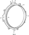
FIG. 2 is a perspective view of a seal carrier; -
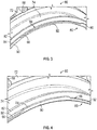
FIG. 3 is a perspective view of a portion of the seal carrier; -
FIG. 4 is a perspective view of a portion of the seal carrier; -
FIG. 5 is a perspective view of a portion of the seal carrier with a seal installed therein; -
FIG. 6 is a perspective view of a portion of the seal carrier with the seal installed therein; and -
FIG. 7 is a perspective view of an attempt to install the seal within the seal carrier in an incorrect orientation. - A detailed description of one or more embodiments of the disclosed apparatus and method are presented herein by way of exemplification and not limitation with reference to the Figures.
-
FIG. 1 schematically illustrates agas turbine engine 20. Thegas turbine engine 20 is disclosed herein as a two-spool turbofan that generally incorporates afan section 22, a compressor section 24, acombustor section 26 and aturbine section 28. Alternative engines might include an augmentor section (not shown) among other systems or features. Thefan section 22 drives air along a bypass flow path B in a bypass duct, while the compressor section 24 drives air along a core flow path C for compression and communication into thecombustor section 26 then expansion through theturbine section 28. Although depicted as a two-spool turbofan gas turbine engine in the disclosed non-limiting embodiment, it should be understood that the concepts described herein are not limited to use with two-spool turbofans as the teachings may be applied to other types of turbine engines including three-spool architectures. - The
exemplary engine 20 generally includes alow speed spool 30 and ahigh speed spool 32 mounted for rotation about an engine central longitudinal axis A relative to an enginestatic structure 36 viaseveral bearing systems 38. It should be understood thatvarious bearing systems 38 at various locations may alternatively or additionally be provided, and the location ofbearing systems 38 may be varied as appropriate to the application. - The
low speed spool 30 generally includes aninner shaft 40 that interconnects afan 42, a low pressure compressor 44 and alow pressure turbine 46. Theinner shaft 40 is connected to thefan 42 through a speed change mechanism, which in exemplarygas turbine engine 20 is illustrated as a gearedarchitecture 48 to drive thefan 42 at a lower speed than thelow speed spool 30. Thehigh speed spool 32 includes anouter shaft 50 that interconnects ahigh pressure compressor 52 andhigh pressure turbine 54. Acombustor 56 is arranged inexemplary gas turbine 20 between thehigh pressure compressor 52 and thehigh pressure turbine 54. An enginestatic structure 36 is arranged generally between thehigh pressure turbine 54 and thelow pressure turbine 46. The enginestatic structure 36 further supports bearingsystems 38 in theturbine section 28. Theinner shaft 40 and theouter shaft 50 are concentric and rotate viabearing systems 38 about the engine central longitudinal axis A which is collinear with their longitudinal axes. - The core airflow is compressed by the low pressure compressor 44 then the
high pressure compressor 52, mixed and burned with fuel in thecombustor 56, then expanded over thehigh pressure turbine 54 andlow pressure turbine 46. Theturbines low speed spool 30 andhigh speed spool 32 in response to the expansion. It will be appreciated that each of the positions of thefan section 22, compressor section 24,combustor section 26,turbine section 28, and fandrive gear system 48 may be varied. For example,gear system 48 may be located aft ofcombustor section 26 or even aft ofturbine section 28, andfan section 22 may be positioned forward or aft of the location ofgear system 48. - The
engine 20 in one example is a high-bypass geared aircraft engine. In a further example, theengine 20 bypass ratio is greater than about six (6), with an example embodiment being greater than about ten (10), the gearedarchitecture 48 is an epicyclic gear train, such as a planetary gear system or other gear system, with a gear reduction ratio of greater than about 2.3 and thelow pressure turbine 46 has a pressure ratio that is greater than about five. In one disclosed embodiment, theengine 20 bypass ratio is greater than about ten (10:1), the fan diameter is significantly larger than that of the low pressure compressor 44, and thelow pressure turbine 46 has a pressure ratio that is greater than about five (5:1).Low pressure turbine 46 pressure ratio is pressure measured prior to inlet oflow pressure turbine 46 as related to the pressure at the outlet of thelow pressure turbine 46 prior to an exhaust nozzle. The gearedarchitecture 48 may be an epicycle gear train, such as a planetary gear system or other gear system, with a gear reduction ratio of greater than about 2.3:1. It should be understood, however, that the above parameters are only exemplary of one embodiment of a geared architecture engine and that the present disclosure is applicable to other gas turbine engines including direct drive turbofans. - A significant amount of thrust is provided by the bypass flow B due to the high bypass ratio. The
fan section 22 of theengine 20 is designed for a particular flight condition--typically cruise at about 0.8 Mach and about 35,000 feet (11,000 meters). The flight condition of 0.8 Mach and 35,000 feet (11,000 meters), with the engine at its best fuel consumption--also known as "bucket cruise Thrust Specific Fuel Consumption ('TSFC)"--is the industry standard parameter of lbm of fuel being burned divided by lbf of thrust the engine produces at that minimum point. "Low fan pressure ratio" is the pressure ratio across the fan blade alone, without a Fan Exit Guide Vane ("FEGV") system. The low fan pressure ratio as disclosed herein according to one non-limiting embodiment is less than about 1.45. "Low corrected fan tip speed" is the actual fan tip speed in ft/sec divided by an industry standard temperature correction of [(Tram °R)/(518.7 °R)]0.5. The "Low corrected fan tip speed" as disclosed herein according to one non-limiting embodiment is less than about 1150 ft/second (350 m/sec). - Referring now to
FIG. 2 , illustrated is aseal carrier 60 that is part of a face seal arrangement. The face seal arrangement may be located at various contemplated locations within thegas turbine engine 20. In some embodiments, the face seal arrangement is located proximate the above-describedbearing systems 38 to seal a bearing compartment. The face seal arrangement includes a housing (not shown) surrounding the seal carrier. Disposed within theseal carrier 60 is aseal 62, as shown inFIGS. 5-7 and described in detail herein. Theseal 62 is substantially circular in cross-section. Theseal carrier 60 is prevented from rotating about the engine centerline axis A via at least one anti-rotation pin assemblies (not shown) that interface with theseal carrier 60. In particular, an anti-rotation pin is positioned in a correspondinganti-rotation slot 64 of theseal carrier 60. In the illustrated embodiments, fouranti-rotation slots 64 are provided, but it is to be understood that different embodiments may include greater or fewer slots. - The
seal carrier 60 is positioned axially relative to the housing using multiple springs (not shown). The springs are spaced circumferentially about theseal carrier 60 and interfaces with theseal carrier 60 via multiple spring fastener features 68. The springs provide axial loading to maintain contact between theseal 60 and a rotating seal plate that is part of the spool or shaft assembly. - Referring now to
FIGS. 2-6 , theseal carrier 60 and theseal 62 are shown with various views.FIGS. 2-4 illustrate theseal carrier 60 andFIGS. 5 and 6 illustrate theseal 62 installed within a groove of theseal carrier 60. Theseal carrier 60 includes amain plate portion 72 that defines theanti-rotation slots 64 and provide flanges for attachment of the spring fastener features 68. Theseal carrier 60 also includes acylindrical body 74 extending away from themain plate portion 72. - At an end of the
cylindrical body 74 distal from themain plate portion 72 is aseal retention structure 80 for installation of theseal 62. Theseal retention structure 80 includes afirst wall 82, asecond wall 84 and abase wall 86. Thefirst wall 82, thesecond wall 84 and thebase wall 86 define acylindrical groove 88 that is configured to receive and retain theseal 62. In the illustrated embodiment, thegroove 88 is substantially U-shaped when taken at a circumferential section location of theseal carrier 60. - The
second seal wall 84 extends radially away from thebase wall 86, but not to a constant radial distance. In particular, thesecond seal wall 84 includes a plurality ofsegments 90 that extend to a maximum radius, the plurality ofsegments 90 having constant radial lengths. In other words, the plurality ofsegments 90 extend to a common radius. Located between, in a circumferential direction, the plurality ofsegments 90 are a plurality of recessedportions 92 of the wall that do not extend as far in the radial direction as the plurality ofsegments 90. The shape and contour of the recessedportions 92 may vary from the example shown in the illustrated embodiments. The positioning of the plurality ofsegments 90 and recessedportions 92 define a second seal wall that extends to a non-uniform radial location. - Avoiding a constant radius ring for the
second seal wall 84 provides numerous benefits. For example, the weight and moment of inertia of theseal carrier 60 are reduced. A higher mass for a seal carrier requires heavier spring loads during operation to avoid any seal separation during operation. Higher spring loads consequently increases the friction generated at the rubbing interface, resulting in higher heat generation and accelerating seal wear over time, in addition to a higher oil flow requirement to mitigate this extra heat generation. Reducing the mass of thesecond seal wall 84 allows mitigation of these issues without having to make more challenging modifications. Therefore, high quality performance is maintained, while improving issues associated with seal wear. - Referring now to
FIG. 7 , features that assist with installation of theseal 62 within thegroove 88 of theseal carrier 60 are illustrated. In particular, the geometry of theseal 62 only allows theseal 62 to be installed in a single, correct orientation, such as the orientation shown inFIGS. 5 and 6 . The correct orientation allows theseal 62 to be inserted into thegroove 88 with a slight clearance between thesecond seal wall 84 and the seal 62 (FIGS. 5 and 6 ). In the illustration ofFIG. 7 , theseal 62 is shown during an attempt to install theseal 62 backwards. Attempting to install theseal 62 in this manner - or any other incorrect orientation - results in an interference condition that prevents full insertion of theseal 62 into thegroove 88. Specifically, the inner side 96 of thesecond seal wall 84 and theseal 62 clash prior to full installation of theseal 62. Installation reliability is therefore improved with the installation features described above. - The term "about" is intended to include the degree of error associated with measurement of the particular quantity based upon the equipment available at the time of filing the application. For example, "about" can include a range of ± 8% or 5%, or 2% of a given value.
- The terminology used herein is for the purpose of describing particular embodiments only and is not intended to be limiting of the present disclosure. As used herein, the singular forms "a", "an" and "the" are intended to include the plural forms as well, unless the context clearly indicates otherwise. It will be further understood that the terms "comprises" and/or "comprising," when used in this specification, specify the presence of stated features, integers, steps, operations, elements, and/or components, but do not preclude the presence or addition of one or more other features, integers, steps, operations, element components, and/or groups thereof.
- While the present disclosure has been described with reference to an exemplary embodiment or embodiments, it will be understood by those skilled in the art that various changes may be made and equivalents may be substituted for elements thereof without departing from the scope of the present disclosure. In addition, many modifications may be made to adapt a particular situation or material to the teachings of the present disclosure without departing from the essential scope thereof. Therefore, it is intended that the present disclosure not be limited to the particular embodiment disclosed as the best mode contemplated for carrying out this present disclosure, but that the present disclosure will include all embodiments falling within the scope of the claims.
Claims (11)
- A face seal assembly comprising:a seal (62); anda seal carrier (160) including a first seal wall (82), a second seal wall (84) and a base seal wall (86), the first seal wall (82), the second seal wall (84) and the base seal wall (86) defining a groove (88) for receiving the seal (62) therein, the second seal wall (84) extending radially outwardly to a non-uniform radial location.
- The face seal assembly of claim 1, wherein the second seal wall (84) includes a plurality of segments (90) extending to a common, first radial location and a plurality of recessed portions (92) extending to a second radial location that is radially inward of the first radial location.
- The face seal assembly of claim 2, wherein each of the plurality of recessed portions (92) extends circumferentially between an adjacent pair of the plurality of segments (84).
- The face seal assembly of claim 1, 2 or 3 wherein the groove (88) is substantially U-shaped.
- The face seal assembly of any of claims 1 to 4, wherein the face seal assembly is disposed in a gas turbine engine (20).
- The face seal assembly of claim 5, wherein the face seal assembly is located adjacent a bearing compartment disposed proximate a main shaft assembly of the gas turbine engine (20).
- The face seal assembly of claim 5, wherein the face seal assembly is located within a compressor section (24) of the gas turbine engine (20).
- A gas turbine engine (20) comprising:a compressor section (24);a combustion section (26);a turbine section (28);a main shaft assembly; andthe face seal assembly of any of claims 1 to 7.
- The face seal assembly of claim 8, wherein the face seal assembly is located adjacent a bearing compartment disposed proximate a main shaft of the gas turbine engine (20).
- The face seal assembly of claim 8, wherein the face seal assembly is located within the compressor section (24).
- A method of assembling a face seal assembly in a gas turbine engine (20), the method comprising disposing at least one seal segment (62) within a groove (88) defined by a first seal wall (82), a second seal wall (84) and a seal base wall (86), the second seal wall (84) extending radially outwardly to a non-uniform radial location.
Applications Claiming Priority (1)
| Application Number | Priority Date | Filing Date | Title |
|---|---|---|---|
| US15/840,458 US10677168B2 (en) | 2017-12-13 | 2017-12-13 | Seal retention assembly for gas turbine engine |
Publications (2)
| Publication Number | Publication Date |
|---|---|
| EP3498984A1 true EP3498984A1 (en) | 2019-06-19 |
| EP3498984B1 EP3498984B1 (en) | 2021-07-21 |
Family
ID=64665049
Family Applications (1)
| Application Number | Title | Priority Date | Filing Date |
|---|---|---|---|
| EP18211987.5A Active EP3498984B1 (en) | 2017-12-13 | 2018-12-12 | Seal retention assembly for gas turbine engine and corresponding method of assembly |
Country Status (2)
| Country | Link |
|---|---|
| US (1) | US10677168B2 (en) |
| EP (1) | EP3498984B1 (en) |
Families Citing this family (6)
| Publication number | Priority date | Publication date | Assignee | Title |
|---|---|---|---|---|
| US12460727B2 (en) * | 2019-09-20 | 2025-11-04 | Rtx Corporation | Self-centering seal and method of using same |
| US11473436B2 (en) * | 2019-10-14 | 2022-10-18 | General Electric Company | Seal assembly |
| CN113669451A (en) * | 2021-08-31 | 2021-11-19 | 湖北三江航天红林探控有限公司 | A kind of sealing structure and its application in high temperature and high pressure system |
| US11773746B2 (en) | 2021-09-10 | 2023-10-03 | Hamilton Sundstrand Corporation | Turbomachinery rotor shroud with variable lattice densities |
| US11994141B2 (en) | 2021-09-10 | 2024-05-28 | Hamilton Sundstrand Corporation | Turbomachinery shaft with variable lattice densities |
| US11802488B2 (en) | 2021-09-10 | 2023-10-31 | Hamilton Sundstrand Corporation | Turbomachinery seal plate with variable lattice densities |
Citations (3)
| Publication number | Priority date | Publication date | Assignee | Title |
|---|---|---|---|---|
| US20100111682A1 (en) * | 2008-10-31 | 2010-05-06 | Patrick Jarvis Scoggins | Crenelated turbine nozzle |
| US20160208923A1 (en) * | 2015-01-20 | 2016-07-21 | United Technologies Corporation | Radial coverage piston ring groove arrangement |
| US20160369642A1 (en) * | 2015-06-22 | 2016-12-22 | United Technologies Corporation | Gas turbine engine seal installation protection |
Family Cites Families (6)
| Publication number | Priority date | Publication date | Assignee | Title |
|---|---|---|---|---|
| US4989700A (en) | 1989-12-28 | 1991-02-05 | Fichtel & Sachs Industries, Inc. | Gas spring with an anti-rattle piston assembly |
| US6196790B1 (en) | 1998-12-17 | 2001-03-06 | United Technologies Corporation | Seal assembly for an intershaft seal in a gas turbine engine |
| US9850771B2 (en) * | 2014-02-07 | 2017-12-26 | United Technologies Corporation | Gas turbine engine sealing arrangement |
| US10215098B2 (en) | 2015-01-22 | 2019-02-26 | United Technologies Corporation | Bearing compartment seal |
| US10161256B2 (en) | 2015-01-22 | 2018-12-25 | Untied Technologies Corporation | Seal with backup seal |
| US9926797B2 (en) | 2015-01-22 | 2018-03-27 | United Technologies Corporation | Flange trapped seal configuration |
-
2017
- 2017-12-13 US US15/840,458 patent/US10677168B2/en active Active
-
2018
- 2018-12-12 EP EP18211987.5A patent/EP3498984B1/en active Active
Patent Citations (3)
| Publication number | Priority date | Publication date | Assignee | Title |
|---|---|---|---|---|
| US20100111682A1 (en) * | 2008-10-31 | 2010-05-06 | Patrick Jarvis Scoggins | Crenelated turbine nozzle |
| US20160208923A1 (en) * | 2015-01-20 | 2016-07-21 | United Technologies Corporation | Radial coverage piston ring groove arrangement |
| US20160369642A1 (en) * | 2015-06-22 | 2016-12-22 | United Technologies Corporation | Gas turbine engine seal installation protection |
Also Published As
| Publication number | Publication date |
|---|---|
| US10677168B2 (en) | 2020-06-09 |
| US20190178166A1 (en) | 2019-06-13 |
| EP3498984B1 (en) | 2021-07-21 |
Similar Documents
| Publication | Publication Date | Title |
|---|---|---|
| EP3498984B1 (en) | Seal retention assembly for gas turbine engine and corresponding method of assembly | |
| US11391172B2 (en) | Piloted retaining plate for a face seal arrangement | |
| EP3502497B1 (en) | Flexible preloaded ball bearing assembly | |
| US9546560B2 (en) | Compact double grounded mechanical carbon seal | |
| EP2900999B1 (en) | Seal damper with improved retention | |
| EP3789589B1 (en) | Hydrostatic seal | |
| EP3653915A1 (en) | Seal disassembly aid | |
| EP3786418A1 (en) | Hydrostatic seal with seal stops | |
| EP2880282B1 (en) | Compressor assembly with stator anti-rotation lug | |
| EP3960993B1 (en) | Face seal carrier arrester | |
| US11674548B2 (en) | Low profile rotating bearing centering spring | |
| EP3772570A1 (en) | Hydrostatic seal with extended carrier arm | |
| EP3816472B1 (en) | Axially rigid curved beam with squeeze damper | |
| EP3611347B1 (en) | Gas turbine engine with stator segments | |
| US10883370B2 (en) | Dovetail weight system for rotor balance | |
| US11002147B2 (en) | Fixed vane pack retaining ring | |
| EP4006310B1 (en) | Face seal arrangement with reduced balance ratio | |
| EP3933170B1 (en) | Mid mount sleeve arrangement | |
| EP3760841B1 (en) | Multi-purpose anti-rotation lock pin | |
| EP4372208A1 (en) | Seal for gas turbine engine | |
| EP4488494B1 (en) | Bearing inner race with sleeve and integrated puller | |
| EP4332353A1 (en) | Thermal conditioning of flange with secondary flow | |
| EP4560114A1 (en) | Piston ring seal | |
| EP3550113A2 (en) | Gas turbine engine having cantilevered stators with sealing members |
Legal Events
| Date | Code | Title | Description |
|---|---|---|---|
| PUAI | Public reference made under article 153(3) epc to a published international application that has entered the european phase |
Free format text: ORIGINAL CODE: 0009012 |
|
| STAA | Information on the status of an ep patent application or granted ep patent |
Free format text: STATUS: THE APPLICATION HAS BEEN PUBLISHED |
|
| AK | Designated contracting states |
Kind code of ref document: A1 Designated state(s): AL AT BE BG CH CY CZ DE DK EE ES FI FR GB GR HR HU IE IS IT LI LT LU LV MC MK MT NL NO PL PT RO RS SE SI SK SM TR |
|
| AX | Request for extension of the european patent |
Extension state: BA ME |
|
| STAA | Information on the status of an ep patent application or granted ep patent |
Free format text: STATUS: REQUEST FOR EXAMINATION WAS MADE |
|
| 17P | Request for examination filed |
Effective date: 20191219 |
|
| RBV | Designated contracting states (corrected) |
Designated state(s): AL AT BE BG CH CY CZ DE DK EE ES FI FR GB GR HR HU IE IS IT LI LT LU LV MC MK MT NL NO PL PT RO RS SE SI SK SM TR |
|
| GRAP | Despatch of communication of intention to grant a patent |
Free format text: ORIGINAL CODE: EPIDOSNIGR1 |
|
| STAA | Information on the status of an ep patent application or granted ep patent |
Free format text: STATUS: GRANT OF PATENT IS INTENDED |
|
| INTG | Intention to grant announced |
Effective date: 20210224 |
|
| RAP1 | Party data changed (applicant data changed or rights of an application transferred) |
Owner name: RAYTHEON TECHNOLOGIES CORPORATION |
|
| GRAS | Grant fee paid |
Free format text: ORIGINAL CODE: EPIDOSNIGR3 |
|
| GRAA | (expected) grant |
Free format text: ORIGINAL CODE: 0009210 |
|
| STAA | Information on the status of an ep patent application or granted ep patent |
Free format text: STATUS: THE PATENT HAS BEEN GRANTED |
|
| AK | Designated contracting states |
Kind code of ref document: B1 Designated state(s): AL AT BE BG CH CY CZ DE DK EE ES FI FR GB GR HR HU IE IS IT LI LT LU LV MC MK MT NL NO PL PT RO RS SE SI SK SM TR |
|
| REG | Reference to a national code |
Ref country code: GB Ref legal event code: FG4D |
|
| REG | Reference to a national code |
Ref country code: CH Ref legal event code: EP |
|
| REG | Reference to a national code |
Ref country code: DE Ref legal event code: R096 Ref document number: 602018020385 Country of ref document: DE |
|
| REG | Reference to a national code |
Ref country code: AT Ref legal event code: REF Ref document number: 1412784 Country of ref document: AT Kind code of ref document: T Effective date: 20210815 |
|
| REG | Reference to a national code |
Ref country code: IE Ref legal event code: FG4D |
|
| REG | Reference to a national code |
Ref country code: LT Ref legal event code: MG9D |
|
| REG | Reference to a national code |
Ref country code: NL Ref legal event code: MP Effective date: 20210721 |
|
| REG | Reference to a national code |
Ref country code: AT Ref legal event code: MK05 Ref document number: 1412784 Country of ref document: AT Kind code of ref document: T Effective date: 20210721 |
|
| PG25 | Lapsed in a contracting state [announced via postgrant information from national office to epo] |
Ref country code: HR Free format text: LAPSE BECAUSE OF FAILURE TO SUBMIT A TRANSLATION OF THE DESCRIPTION OR TO PAY THE FEE WITHIN THE PRESCRIBED TIME-LIMIT Effective date: 20210721 Ref country code: FI Free format text: LAPSE BECAUSE OF FAILURE TO SUBMIT A TRANSLATION OF THE DESCRIPTION OR TO PAY THE FEE WITHIN THE PRESCRIBED TIME-LIMIT Effective date: 20210721 Ref country code: ES Free format text: LAPSE BECAUSE OF FAILURE TO SUBMIT A TRANSLATION OF THE DESCRIPTION OR TO PAY THE FEE WITHIN THE PRESCRIBED TIME-LIMIT Effective date: 20210721 Ref country code: RS Free format text: LAPSE BECAUSE OF FAILURE TO SUBMIT A TRANSLATION OF THE DESCRIPTION OR TO PAY THE FEE WITHIN THE PRESCRIBED TIME-LIMIT Effective date: 20210721 Ref country code: SE Free format text: LAPSE BECAUSE OF FAILURE TO SUBMIT A TRANSLATION OF THE DESCRIPTION OR TO PAY THE FEE WITHIN THE PRESCRIBED TIME-LIMIT Effective date: 20210721 Ref country code: LT Free format text: LAPSE BECAUSE OF FAILURE TO SUBMIT A TRANSLATION OF THE DESCRIPTION OR TO PAY THE FEE WITHIN THE PRESCRIBED TIME-LIMIT Effective date: 20210721 Ref country code: BG Free format text: LAPSE BECAUSE OF FAILURE TO SUBMIT A TRANSLATION OF THE DESCRIPTION OR TO PAY THE FEE WITHIN THE PRESCRIBED TIME-LIMIT Effective date: 20211021 Ref country code: AT Free format text: LAPSE BECAUSE OF FAILURE TO SUBMIT A TRANSLATION OF THE DESCRIPTION OR TO PAY THE FEE WITHIN THE PRESCRIBED TIME-LIMIT Effective date: 20210721 Ref country code: PT Free format text: LAPSE BECAUSE OF FAILURE TO SUBMIT A TRANSLATION OF THE DESCRIPTION OR TO PAY THE FEE WITHIN THE PRESCRIBED TIME-LIMIT Effective date: 20211122 Ref country code: NL Free format text: LAPSE BECAUSE OF FAILURE TO SUBMIT A TRANSLATION OF THE DESCRIPTION OR TO PAY THE FEE WITHIN THE PRESCRIBED TIME-LIMIT Effective date: 20210721 Ref country code: NO Free format text: LAPSE BECAUSE OF FAILURE TO SUBMIT A TRANSLATION OF THE DESCRIPTION OR TO PAY THE FEE WITHIN THE PRESCRIBED TIME-LIMIT Effective date: 20211021 |
|
| PG25 | Lapsed in a contracting state [announced via postgrant information from national office to epo] |
Ref country code: PL Free format text: LAPSE BECAUSE OF FAILURE TO SUBMIT A TRANSLATION OF THE DESCRIPTION OR TO PAY THE FEE WITHIN THE PRESCRIBED TIME-LIMIT Effective date: 20210721 Ref country code: LV Free format text: LAPSE BECAUSE OF FAILURE TO SUBMIT A TRANSLATION OF THE DESCRIPTION OR TO PAY THE FEE WITHIN THE PRESCRIBED TIME-LIMIT Effective date: 20210721 Ref country code: GR Free format text: LAPSE BECAUSE OF FAILURE TO SUBMIT A TRANSLATION OF THE DESCRIPTION OR TO PAY THE FEE WITHIN THE PRESCRIBED TIME-LIMIT Effective date: 20211022 |
|
| REG | Reference to a national code |
Ref country code: DE Ref legal event code: R097 Ref document number: 602018020385 Country of ref document: DE |
|
| PG25 | Lapsed in a contracting state [announced via postgrant information from national office to epo] |
Ref country code: DK Free format text: LAPSE BECAUSE OF FAILURE TO SUBMIT A TRANSLATION OF THE DESCRIPTION OR TO PAY THE FEE WITHIN THE PRESCRIBED TIME-LIMIT Effective date: 20210721 |
|
| PLBE | No opposition filed within time limit |
Free format text: ORIGINAL CODE: 0009261 |
|
| STAA | Information on the status of an ep patent application or granted ep patent |
Free format text: STATUS: NO OPPOSITION FILED WITHIN TIME LIMIT |
|
| PG25 | Lapsed in a contracting state [announced via postgrant information from national office to epo] |
Ref country code: SM Free format text: LAPSE BECAUSE OF FAILURE TO SUBMIT A TRANSLATION OF THE DESCRIPTION OR TO PAY THE FEE WITHIN THE PRESCRIBED TIME-LIMIT Effective date: 20210721 Ref country code: SK Free format text: LAPSE BECAUSE OF FAILURE TO SUBMIT A TRANSLATION OF THE DESCRIPTION OR TO PAY THE FEE WITHIN THE PRESCRIBED TIME-LIMIT Effective date: 20210721 Ref country code: RO Free format text: LAPSE BECAUSE OF FAILURE TO SUBMIT A TRANSLATION OF THE DESCRIPTION OR TO PAY THE FEE WITHIN THE PRESCRIBED TIME-LIMIT Effective date: 20210721 Ref country code: EE Free format text: LAPSE BECAUSE OF FAILURE TO SUBMIT A TRANSLATION OF THE DESCRIPTION OR TO PAY THE FEE WITHIN THE PRESCRIBED TIME-LIMIT Effective date: 20210721 Ref country code: CZ Free format text: LAPSE BECAUSE OF FAILURE TO SUBMIT A TRANSLATION OF THE DESCRIPTION OR TO PAY THE FEE WITHIN THE PRESCRIBED TIME-LIMIT Effective date: 20210721 Ref country code: AL Free format text: LAPSE BECAUSE OF FAILURE TO SUBMIT A TRANSLATION OF THE DESCRIPTION OR TO PAY THE FEE WITHIN THE PRESCRIBED TIME-LIMIT Effective date: 20210721 |
|
| 26N | No opposition filed |
Effective date: 20220422 |
|
| PG25 | Lapsed in a contracting state [announced via postgrant information from national office to epo] |
Ref country code: MC Free format text: LAPSE BECAUSE OF FAILURE TO SUBMIT A TRANSLATION OF THE DESCRIPTION OR TO PAY THE FEE WITHIN THE PRESCRIBED TIME-LIMIT Effective date: 20210721 Ref country code: IT Free format text: LAPSE BECAUSE OF FAILURE TO SUBMIT A TRANSLATION OF THE DESCRIPTION OR TO PAY THE FEE WITHIN THE PRESCRIBED TIME-LIMIT Effective date: 20210721 |
|
| REG | Reference to a national code |
Ref country code: CH Ref legal event code: PL |
|
| REG | Reference to a national code |
Ref country code: BE Ref legal event code: MM Effective date: 20211231 |
|
| PG25 | Lapsed in a contracting state [announced via postgrant information from national office to epo] |
Ref country code: LU Free format text: LAPSE BECAUSE OF NON-PAYMENT OF DUE FEES Effective date: 20211212 Ref country code: IE Free format text: LAPSE BECAUSE OF NON-PAYMENT OF DUE FEES Effective date: 20211212 |
|
| PG25 | Lapsed in a contracting state [announced via postgrant information from national office to epo] |
Ref country code: BE Free format text: LAPSE BECAUSE OF NON-PAYMENT OF DUE FEES Effective date: 20211231 |
|
| PG25 | Lapsed in a contracting state [announced via postgrant information from national office to epo] |
Ref country code: LI Free format text: LAPSE BECAUSE OF NON-PAYMENT OF DUE FEES Effective date: 20211231 Ref country code: CH Free format text: LAPSE BECAUSE OF NON-PAYMENT OF DUE FEES Effective date: 20211231 |
|
| P01 | Opt-out of the competence of the unified patent court (upc) registered |
Effective date: 20230521 |
|
| PG25 | Lapsed in a contracting state [announced via postgrant information from national office to epo] |
Ref country code: CY Free format text: LAPSE BECAUSE OF FAILURE TO SUBMIT A TRANSLATION OF THE DESCRIPTION OR TO PAY THE FEE WITHIN THE PRESCRIBED TIME-LIMIT Effective date: 20210721 |
|
| PG25 | Lapsed in a contracting state [announced via postgrant information from national office to epo] |
Ref country code: HU Free format text: LAPSE BECAUSE OF FAILURE TO SUBMIT A TRANSLATION OF THE DESCRIPTION OR TO PAY THE FEE WITHIN THE PRESCRIBED TIME-LIMIT; INVALID AB INITIO Effective date: 20181212 |
|
| PG25 | Lapsed in a contracting state [announced via postgrant information from national office to epo] |
Ref country code: MK Free format text: LAPSE BECAUSE OF FAILURE TO SUBMIT A TRANSLATION OF THE DESCRIPTION OR TO PAY THE FEE WITHIN THE PRESCRIBED TIME-LIMIT Effective date: 20210721 |
|
| PG25 | Lapsed in a contracting state [announced via postgrant information from national office to epo] |
Ref country code: TR Free format text: LAPSE BECAUSE OF FAILURE TO SUBMIT A TRANSLATION OF THE DESCRIPTION OR TO PAY THE FEE WITHIN THE PRESCRIBED TIME-LIMIT Effective date: 20210721 |
|
| PG25 | Lapsed in a contracting state [announced via postgrant information from national office to epo] |
Ref country code: MT Free format text: LAPSE BECAUSE OF FAILURE TO SUBMIT A TRANSLATION OF THE DESCRIPTION OR TO PAY THE FEE WITHIN THE PRESCRIBED TIME-LIMIT Effective date: 20210721 |
|
| REG | Reference to a national code |
Ref country code: DE Ref legal event code: R081 Ref document number: 602018020385 Country of ref document: DE Owner name: RTX CORPORATION (N.D.GES.D. STAATES DELAWARE),, US Free format text: FORMER OWNER: RAYTHEON TECHNOLOGIES CORPORATION, FARMINGTON, CT, US |
|
| PGFP | Annual fee paid to national office [announced via postgrant information from national office to epo] |
Ref country code: DE Payment date: 20251126 Year of fee payment: 8 |
|
| PGFP | Annual fee paid to national office [announced via postgrant information from national office to epo] |
Ref country code: GB Payment date: 20251120 Year of fee payment: 8 |
|
| PGFP | Annual fee paid to national office [announced via postgrant information from national office to epo] |
Ref country code: FR Payment date: 20251120 Year of fee payment: 8 |