EP3498976A2 - Cmc component with flowpath surface ribs - Google Patents
Cmc component with flowpath surface ribs Download PDFInfo
- Publication number
- EP3498976A2 EP3498976A2 EP18212690.4A EP18212690A EP3498976A2 EP 3498976 A2 EP3498976 A2 EP 3498976A2 EP 18212690 A EP18212690 A EP 18212690A EP 3498976 A2 EP3498976 A2 EP 3498976A2
- Authority
- EP
- European Patent Office
- Prior art keywords
- ribs
- turbomachine
- airfoil element
- turbomachine airfoil
- cmc
- Prior art date
- Legal status (The legal status is an assumption and is not a legal conclusion. Google has not performed a legal analysis and makes no representation as to the accuracy of the status listed.)
- Granted
Links
Images



Classifications
-
- F—MECHANICAL ENGINEERING; LIGHTING; HEATING; WEAPONS; BLASTING
- F01—MACHINES OR ENGINES IN GENERAL; ENGINE PLANTS IN GENERAL; STEAM ENGINES
- F01D—NON-POSITIVE DISPLACEMENT MACHINES OR ENGINES, e.g. STEAM TURBINES
- F01D5/00—Blades; Blade-carrying members; Heating, heat-insulating, cooling or antivibration means on the blades or the members
- F01D5/12—Blades
- F01D5/14—Form or construction
- F01D5/141—Shape, i.e. outer, aerodynamic form
- F01D5/145—Means for influencing boundary layers or secondary circulations
-
- F—MECHANICAL ENGINEERING; LIGHTING; HEATING; WEAPONS; BLASTING
- F01—MACHINES OR ENGINES IN GENERAL; ENGINE PLANTS IN GENERAL; STEAM ENGINES
- F01D—NON-POSITIVE DISPLACEMENT MACHINES OR ENGINES, e.g. STEAM TURBINES
- F01D5/00—Blades; Blade-carrying members; Heating, heat-insulating, cooling or antivibration means on the blades or the members
- F01D5/12—Blades
- F01D5/14—Form or construction
- F01D5/141—Shape, i.e. outer, aerodynamic form
-
- F—MECHANICAL ENGINEERING; LIGHTING; HEATING; WEAPONS; BLASTING
- F01—MACHINES OR ENGINES IN GENERAL; ENGINE PLANTS IN GENERAL; STEAM ENGINES
- F01D—NON-POSITIVE DISPLACEMENT MACHINES OR ENGINES, e.g. STEAM TURBINES
- F01D11/00—Preventing or minimising internal leakage of working-fluid, e.g. between stages
- F01D11/08—Preventing or minimising internal leakage of working-fluid, e.g. between stages for sealing space between rotor blade tips and stator
-
- F—MECHANICAL ENGINEERING; LIGHTING; HEATING; WEAPONS; BLASTING
- F01—MACHINES OR ENGINES IN GENERAL; ENGINE PLANTS IN GENERAL; STEAM ENGINES
- F01D—NON-POSITIVE DISPLACEMENT MACHINES OR ENGINES, e.g. STEAM TURBINES
- F01D11/00—Preventing or minimising internal leakage of working-fluid, e.g. between stages
- F01D11/08—Preventing or minimising internal leakage of working-fluid, e.g. between stages for sealing space between rotor blade tips and stator
- F01D11/14—Adjusting or regulating tip-clearance, i.e. distance between rotor-blade tips and stator casing
-
- F—MECHANICAL ENGINEERING; LIGHTING; HEATING; WEAPONS; BLASTING
- F01—MACHINES OR ENGINES IN GENERAL; ENGINE PLANTS IN GENERAL; STEAM ENGINES
- F01D—NON-POSITIVE DISPLACEMENT MACHINES OR ENGINES, e.g. STEAM TURBINES
- F01D25/00—Component parts, details, or accessories, not provided for in, or of interest apart from, other groups
- F01D25/005—Selecting particular materials
-
- F—MECHANICAL ENGINEERING; LIGHTING; HEATING; WEAPONS; BLASTING
- F01—MACHINES OR ENGINES IN GENERAL; ENGINE PLANTS IN GENERAL; STEAM ENGINES
- F01D—NON-POSITIVE DISPLACEMENT MACHINES OR ENGINES, e.g. STEAM TURBINES
- F01D5/00—Blades; Blade-carrying members; Heating, heat-insulating, cooling or antivibration means on the blades or the members
- F01D5/12—Blades
- F01D5/14—Form or construction
- F01D5/141—Shape, i.e. outer, aerodynamic form
- F01D5/142—Shape, i.e. outer, aerodynamic form of the blades of successive rotor or stator blade-rows
-
- F—MECHANICAL ENGINEERING; LIGHTING; HEATING; WEAPONS; BLASTING
- F01—MACHINES OR ENGINES IN GENERAL; ENGINE PLANTS IN GENERAL; STEAM ENGINES
- F01D—NON-POSITIVE DISPLACEMENT MACHINES OR ENGINES, e.g. STEAM TURBINES
- F01D5/00—Blades; Blade-carrying members; Heating, heat-insulating, cooling or antivibration means on the blades or the members
- F01D5/12—Blades
- F01D5/28—Selecting particular materials; Particular measures relating thereto; Measures against erosion or corrosion
-
- F—MECHANICAL ENGINEERING; LIGHTING; HEATING; WEAPONS; BLASTING
- F01—MACHINES OR ENGINES IN GENERAL; ENGINE PLANTS IN GENERAL; STEAM ENGINES
- F01D—NON-POSITIVE DISPLACEMENT MACHINES OR ENGINES, e.g. STEAM TURBINES
- F01D5/00—Blades; Blade-carrying members; Heating, heat-insulating, cooling or antivibration means on the blades or the members
- F01D5/12—Blades
- F01D5/28—Selecting particular materials; Particular measures relating thereto; Measures against erosion or corrosion
- F01D5/282—Selecting composite materials, e.g. blades with reinforcing filaments
-
- F—MECHANICAL ENGINEERING; LIGHTING; HEATING; WEAPONS; BLASTING
- F01—MACHINES OR ENGINES IN GENERAL; ENGINE PLANTS IN GENERAL; STEAM ENGINES
- F01D—NON-POSITIVE DISPLACEMENT MACHINES OR ENGINES, e.g. STEAM TURBINES
- F01D5/00—Blades; Blade-carrying members; Heating, heat-insulating, cooling or antivibration means on the blades or the members
- F01D5/12—Blades
- F01D5/28—Selecting particular materials; Particular measures relating thereto; Measures against erosion or corrosion
- F01D5/284—Selection of ceramic materials
-
- F—MECHANICAL ENGINEERING; LIGHTING; HEATING; WEAPONS; BLASTING
- F05—INDEXING SCHEMES RELATING TO ENGINES OR PUMPS IN VARIOUS SUBCLASSES OF CLASSES F01-F04
- F05D—INDEXING SCHEME FOR ASPECTS RELATING TO NON-POSITIVE-DISPLACEMENT MACHINES OR ENGINES, GAS-TURBINES OR JET-PROPULSION PLANTS
- F05D2220/00—Application
- F05D2220/30—Application in turbines
- F05D2220/32—Application in turbines in gas turbines
- F05D2220/323—Application in turbines in gas turbines for aircraft propulsion, e.g. jet engines
-
- F—MECHANICAL ENGINEERING; LIGHTING; HEATING; WEAPONS; BLASTING
- F05—INDEXING SCHEMES RELATING TO ENGINES OR PUMPS IN VARIOUS SUBCLASSES OF CLASSES F01-F04
- F05D—INDEXING SCHEME FOR ASPECTS RELATING TO NON-POSITIVE-DISPLACEMENT MACHINES OR ENGINES, GAS-TURBINES OR JET-PROPULSION PLANTS
- F05D2230/00—Manufacture
- F05D2230/20—Manufacture essentially without removing material
-
- F—MECHANICAL ENGINEERING; LIGHTING; HEATING; WEAPONS; BLASTING
- F05—INDEXING SCHEMES RELATING TO ENGINES OR PUMPS IN VARIOUS SUBCLASSES OF CLASSES F01-F04
- F05D—INDEXING SCHEME FOR ASPECTS RELATING TO NON-POSITIVE-DISPLACEMENT MACHINES OR ENGINES, GAS-TURBINES OR JET-PROPULSION PLANTS
- F05D2230/00—Manufacture
- F05D2230/90—Coating; Surface treatment
-
- F—MECHANICAL ENGINEERING; LIGHTING; HEATING; WEAPONS; BLASTING
- F05—INDEXING SCHEMES RELATING TO ENGINES OR PUMPS IN VARIOUS SUBCLASSES OF CLASSES F01-F04
- F05D—INDEXING SCHEME FOR ASPECTS RELATING TO NON-POSITIVE-DISPLACEMENT MACHINES OR ENGINES, GAS-TURBINES OR JET-PROPULSION PLANTS
- F05D2240/00—Components
- F05D2240/10—Stators
- F05D2240/11—Shroud seal segments
-
- F—MECHANICAL ENGINEERING; LIGHTING; HEATING; WEAPONS; BLASTING
- F05—INDEXING SCHEMES RELATING TO ENGINES OR PUMPS IN VARIOUS SUBCLASSES OF CLASSES F01-F04
- F05D—INDEXING SCHEME FOR ASPECTS RELATING TO NON-POSITIVE-DISPLACEMENT MACHINES OR ENGINES, GAS-TURBINES OR JET-PROPULSION PLANTS
- F05D2240/00—Components
- F05D2240/20—Rotors
- F05D2240/30—Characteristics of rotor blades, i.e. of any element transforming dynamic fluid energy to or from rotational energy and being attached to a rotor
- F05D2240/305—Characteristics of rotor blades, i.e. of any element transforming dynamic fluid energy to or from rotational energy and being attached to a rotor related to the pressure side of a rotor blade
-
- F—MECHANICAL ENGINEERING; LIGHTING; HEATING; WEAPONS; BLASTING
- F05—INDEXING SCHEMES RELATING TO ENGINES OR PUMPS IN VARIOUS SUBCLASSES OF CLASSES F01-F04
- F05D—INDEXING SCHEME FOR ASPECTS RELATING TO NON-POSITIVE-DISPLACEMENT MACHINES OR ENGINES, GAS-TURBINES OR JET-PROPULSION PLANTS
- F05D2260/00—Function
- F05D2260/97—Reducing windage losses
-
- F—MECHANICAL ENGINEERING; LIGHTING; HEATING; WEAPONS; BLASTING
- F05—INDEXING SCHEMES RELATING TO ENGINES OR PUMPS IN VARIOUS SUBCLASSES OF CLASSES F01-F04
- F05D—INDEXING SCHEME FOR ASPECTS RELATING TO NON-POSITIVE-DISPLACEMENT MACHINES OR ENGINES, GAS-TURBINES OR JET-PROPULSION PLANTS
- F05D2300/00—Materials; Properties thereof
- F05D2300/20—Oxide or non-oxide ceramics
- F05D2300/22—Non-oxide ceramics
- F05D2300/222—Silicon
-
- F—MECHANICAL ENGINEERING; LIGHTING; HEATING; WEAPONS; BLASTING
- F05—INDEXING SCHEMES RELATING TO ENGINES OR PUMPS IN VARIOUS SUBCLASSES OF CLASSES F01-F04
- F05D—INDEXING SCHEME FOR ASPECTS RELATING TO NON-POSITIVE-DISPLACEMENT MACHINES OR ENGINES, GAS-TURBINES OR JET-PROPULSION PLANTS
- F05D2300/00—Materials; Properties thereof
- F05D2300/60—Properties or characteristics given to material by treatment or manufacturing
- F05D2300/603—Composites; e.g. fibre-reinforced
-
- F—MECHANICAL ENGINEERING; LIGHTING; HEATING; WEAPONS; BLASTING
- F05—INDEXING SCHEMES RELATING TO ENGINES OR PUMPS IN VARIOUS SUBCLASSES OF CLASSES F01-F04
- F05D—INDEXING SCHEME FOR ASPECTS RELATING TO NON-POSITIVE-DISPLACEMENT MACHINES OR ENGINES, GAS-TURBINES OR JET-PROPULSION PLANTS
- F05D2300/00—Materials; Properties thereof
- F05D2300/60—Properties or characteristics given to material by treatment or manufacturing
- F05D2300/603—Composites; e.g. fibre-reinforced
- F05D2300/6033—Ceramic matrix composites [CMC]
-
- F—MECHANICAL ENGINEERING; LIGHTING; HEATING; WEAPONS; BLASTING
- F05—INDEXING SCHEMES RELATING TO ENGINES OR PUMPS IN VARIOUS SUBCLASSES OF CLASSES F01-F04
- F05D—INDEXING SCHEME FOR ASPECTS RELATING TO NON-POSITIVE-DISPLACEMENT MACHINES OR ENGINES, GAS-TURBINES OR JET-PROPULSION PLANTS
- F05D2300/00—Materials; Properties thereof
- F05D2300/60—Properties or characteristics given to material by treatment or manufacturing
- F05D2300/614—Fibres or filaments
-
- Y—GENERAL TAGGING OF NEW TECHNOLOGICAL DEVELOPMENTS; GENERAL TAGGING OF CROSS-SECTIONAL TECHNOLOGIES SPANNING OVER SEVERAL SECTIONS OF THE IPC; TECHNICAL SUBJECTS COVERED BY FORMER USPC CROSS-REFERENCE ART COLLECTIONS [XRACs] AND DIGESTS
- Y02—TECHNOLOGIES OR APPLICATIONS FOR MITIGATION OR ADAPTATION AGAINST CLIMATE CHANGE
- Y02T—CLIMATE CHANGE MITIGATION TECHNOLOGIES RELATED TO TRANSPORTATION
- Y02T50/00—Aeronautics or air transport
- Y02T50/60—Efficient propulsion technologies, e.g. for aircraft
Definitions
- the disclosure relates to turbomachinery. More particularly, the disclosure relates to ceramic and ceramic matrix composite (CMC) components along the gaspath of turbine sections of such turbomachinery.
- CMC ceramic matrix composite
- CMC has been proposed for wide use in hot sections of gas turbine engines (broadly inclusive of engines used in propulsion via thrust, other propulsive engines, industrial gas turbines, and the like).
- Particular structures proposed for CMC use include turbine blades and vanes (e.g., United States Patent Application Publication 20100189556A1 , Propheter-Hinckley et al., July 29, 2010, "Segmented Ceramic Matrix Composite Turbine Airfoil Component"), combustor components (e.g., United States Patent Application Publication 20170314785A1, Vargas, November 2, 2017 , "Ceramic and Ceramic Matrix Composite Attachment Methods and Systems"), and blade outer air seals (BOAS) (e.g., United States Patent Application Publication 20160215645A1, McCaffrey, July 28, 2016 , "Blade Outer Air Seal Made of Ceramic Matrix Composite”).
- turbine blades and vanes e.g., United States Patent Application Publication 20100189556A1 , Propheter-H
- turbomachine airfoil element comprising: a substrate defining an airfoil having a pressure side and a suction side; and a plurality of fiber composite ribs along the pressure side.
- An embodiment of the foregoing may additionally and/or alternatively include the turbomachine airfoil element being a blade having a free tip.
- a further embodiment of any of the foregoing embodiments may additionally and/or alternatively include the ribs converging toward each other from upstream to downstream (i.e. from the leading edge to the trailing edge).
- a further embodiment of any of the foregoing embodiments may additionally and/or alternatively include the ribs comprising a plurality of short ribs alternating with a plurality of long ribs.
- a further embodiment of any of the foregoing embodiments may additionally and/or alternatively include the ribs shifting tipward (or radially outward) from upstream to downstream.
- a further embodiment of any of the foregoing embodiments may additionally and/or alternatively include the ribs being only along an outboard half of the pressure side.
- a further embodiment of any of the foregoing embodiments may additionally and/or alternatively include the turbomachine airfoil element being non-hollow.
- a further embodiment of any of the foregoing embodiments may additionally and/or alternatively include the turbomachine airfoil element lacking internal cooling passageways.
- a further embodiment of any of the foregoing embodiments may additionally and/or alternatively include the turbomachine airfoil element lacking film cooling holes adjacent the plurality of ribs.
- a further embodiment of any of the foregoing embodiments may additionally and/or alternatively include each rib comprising a stack of tapes, the tapes each comprising a plurality of fiber bundles.
- a further embodiment of any of the foregoing embodiments may additionally and/or alternatively include the fiber composite ribs being ceramic matrix composite (CMC).
- CMC ceramic matrix composite
- a further embodiment of any of the foregoing embodiments may additionally and/or alternatively include the substrate comprising a CMC.
- a further embodiment of any of the foregoing embodiments may additionally and/or alternatively include the CMC of the substrate and the CMC of the ribs each comprising: a silicon-based matrix; and silicon-based fibers embedded in the matrix.
- a further embodiment of any of the foregoing embodiments may additionally and/or alternatively include the CMC comprising: a silicon-based matrix; and silicon-based fibers embedded in the matrix.
- a further embodiment of any of the foregoing embodiments may additionally and/or alternatively include a coating over the ribs and extending beyond the ribs.
- a further embodiment of any of the foregoing embodiments may additionally and/or alternatively include a turbomachine including a stage of the turbomachine airfoil elements, the turbomachine airfoil elements being blades, and the turbomachine further comprising a blade outer airseal adjacent tips of the blades.
- a further embodiment of any of the foregoing embodiments may additionally and/or alternatively include a method for using the turbomachine airfoil element.
- the method comprises: running a stage of said airfoil elements forming a blade stage; and the ribs diverting gas flow along the pressure sides relatively toward the respective trailing edges and away from the respective tips.
- a gas turbine engine comprising: a gaspath, a component along the gaspath comprising: a substrate; and a plurality of fiber composite ribs along the gaspath.
- a further embodiment of any of the foregoing embodiments may additionally and/or alternatively include the component being a blade outer airseal and the ribs being along an ID (inner diameter) face of the substrate.
- Another aspect of the disclosure which the Applicant expressly reserves the right to claim independently, involves a method for guiding gas flow along a surface of a component of a turbomachine, the method comprising: providing a plurality of fiber composite ribs along the surface parallel to a desired direction of the gas flow.
- the ribs may have any of the features discussed above.
- FIG. 1 is a schematic illustration of a gas turbine engine 10.
- the illustrated engine is a turbofan used to produce propulsive thrust in aerospace applications.
- relevant gas turbine engines may also include turbojets, turboprops, turboshafts, industrial gas turbines (IGT), and the like.
- IGT industrial gas turbines
- the gas turbine engine has a central longitudinal axis 500.
- the gas turbine engine generally has a fan section 12 through which an inlet flow 520 of ambient air is propelled by a fan 14, a compressor 16 for pressurizing the air 520-1 received from the fan 14, and a combustor 18 wherein the compressed air is mixed with fuel and ignited for generating combustion gases.
- the inlet flow 520 splits into a first or core portion 520-1 flowing along the gaspath (core flowpath) 510 and a bypass portion 520-2 flowing along a bypass flowpath 512.
- core flowpath gaspath
- bypass flowpath 512 bypass flowpath 512
- the gas turbine engine 10 further comprises a turbine 20 for extracting energy from the combustion gases.
- Fuel is injected into the combustor 18 of the gas turbine engine 10 for mixing with the compressed air from the compressor 16 and ignition of the resultant mixture.
- the fan 14, compressor 16, combustor 18, and turbine 20 are typically all concentric about a central longitudinal axis 500 of the gas turbine engine 10.
- the compressor and turbine may each contain multiple sections. Each section includes one or more stages of rotor blades interspersed with one or more stages of stator vanes.
- the exemplary configuration has two compressor sections and two turbine sections. From upstream to downstream along the gaspath 510, these include a Low Pressure Compressor section (LPC) 16-1, a High Pressure Compressor section (HPC) 16-2, a High Pressure Turbine section (HPT) 20-2, and a Low Pressure Turbine section (LPT) 20-1.
- LPC Low Pressure Compressor section
- HPC High Pressure Compressor section
- HPT High Pressure Turbine section
- the exemplary rotors of the LPC and LPT are formed to rotate as a first unit or low pressure spool with the LPT driving the LPC.
- the HPT and HPC rotors are arranged as a high pressure spool.
- the fan may be driven by the low pressure spool either directly or via a reduction gearbox 30.
- Other configurations are, however, known.
- the exemplary engine comprises a fan case 32 and a core case 34.
- the core case has sections along the corresponding sections of the engine core (e.g. an LPC case section, an HPC case section, a HPT case section, and an LPT case section).
- Each of the LPC, HPC, HPT, and LPT sections has several stages of blades of the associated rotor. Interspersed with the blades are stages of stator vanes.
- FIG. 5 shows a prior art CMC (e.g., silicon carbide fibers in silicon carbide matrix) turbine blade 101 having an airfoil 102 extending from an inboard end 104 at a platform 106 to an outboard end 108 at a tip 110.
- the airfoil exterior (gaspath-facing) surface extends from an upstream leading edge 112 to a downstream trailing edge 114 and has a pressure side 116 and a suction side 118.
- a protuberant attachment root 120 depends from the underside of the platform 106 for attaching the blade to a disk.
- Alternative blade configurations are integrally formed with the disk (integrally bladed rotors (IBR) or blisks).
- the exemplary blade lacks internal cooling air passages, generally, and film cooling holes to the airfoil surface, particularly. This highlights one potential area of advantage of CMC blades relative to metallic blades.
- Use of cooling air creates several inefficiencies. First, it cools and dilutes the combustion gases, thereby reducing the amount of energy that could be extracted by the turbine. Second, diversion of cooling air reduces the amount of air that could be driven through the bypass flowpath, thereby further reducing thrust. Nevertheless, the blades may have internal cooling passages and there may be film cooling.
- the film cooling holes could be positioned between the ribs. This may counter vortex formation.
- the centrifugal action causes the gas flow 520-1A (a portion of the core flow 520-1) along the pressure side to radially outwardly diverge and form a leakage flow over the tip toward the suction side (e.g., between the tip and a blade outer air seal (BOAS)). This reduces efficiency of energy extraction from the gas.
- BOAS blade outer air seal
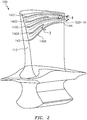
- FIG. 2 shows a modified blade 100 having a radially or spanwise arrayed plurality of surface ribs 140A, 140B, 140C, 140D, 140E (collectively 140).
- Each rib extends from a leading/upstream end 142 to a trailing/downstream end 144.
- the leading ends are all close to the leading edge 112 (e.g., within 10% of the local distance along the pressure side from the leading edge to the trailing edge).
- the ribs are oriented to guide the gas flow 520-1A to reduce or minimize leakage over the tip.
- the spanwise spacing between any given two ribs generally converges from upstream to downstream.
- the exemplary embodiment has alternating essentially full length ribs 140A, 140C, and 140E with their downstream ends 144 relatively near the trailing edge (e.g., within 10% as described for the leading ends 142 relative to the airfoil leading edge) and shorter ribs 140B and 140D (e.g., with their ends 144 terminating well short of the trailing edge (e.g., at least 25% or 35% shy of the trailing edge)).
- This alternating/interdigitated arrangement of ribs allows for sufficient density of ribs near the leading edge to provide a desired guidance of the flow while not interfering with that flow guidance near the trailing edge.
- the ribs are close to parallel to the tip. Near the root, the ribs radially diverge toward the tip from upstream to downstream. The use of alternating shorter ribs also reduces rotating mass relative to hypothetical use of only full-length ribs.
- the ribs may have non-uniform cross-section between the leading/upstream end 142 and the trailing/downstream end 144.
- a cross-section near the leading/upstream end 142 may be greater than that near the trailing/downstream end 144 (e.g., wider or taller).
- the greater cross-section upstream may allow for greater flow turning and handling greater stresses.
- the taper downstream may be for aerodynamic purposes such as avoiding vortex formation.
- leading end of the ribs may be aerodynamically shaped for minimizing losses.
- the exemplary ribs are located along an outboard portion of the airfoil (e.g., along an outboard half). This may have several advantages. First, is simple reduction of cost relative to having ribs along the entire span. Second, is it limits risk of creating turbulence along the inboard portion of the airfoil (whereas turbulence may otherwise be present near the tip). Also, the added rotating weight of ribs on the inboard portion is avoided. However, in further variations, the ribs can be located along an inboard portion and/or along a platform surface.
- the illustrated example lacks any surface film cooling holes.
- the surface ribs in the example are not associated with any discharge from film cooling holes. Nevertheless, this does not preclude the ribs being used on film-cooled embodiments.
- FIG. 3 is a partial sectional view of the airfoil taken transverse to a rib 140. This shows the blade along the airfoil as comprising a CMC substrate 160 of a main body of the airfoil; a core substrate 162 of the rib atop a surface 164 of the substrate 160, and a coating 166.
- the exemplary coating is a two layer coating having first layer 168 and a second layer 170.
- An exemplary second layer is an environmental barrier coating (EBC - typically a ceramic) and an exemplary first layer is a bond coat to improve adhesion of the EBC to the CMC substrate.
- EBC environmental barrier coating
- Exemplary EBC and bond coats are disclosed in United States Patent Application Publication 20060280952A1 (the '952 publication), of Hazel et al., published December 14, 2006, and entitled "Bond coat for corrosion resistant EBC for silicon-containing substrate and processes for preparing same".
- the '952 publication discloses silicon-containing bond coats and silicide-containing bond coats.
- An exemplary bond coat is applied by spray or vapor deposition.
- Exemplary silicon, silicate, or silica bond coats may comprise one or more layers formed from rare earth silicates such as a mullite layer, a mullite-alkaline earth aluminosilicate mixture layer, an yttrium monosilicate layer, an ytterbium doped yttrium disilicate layer, a barium strontium aluminosilicate layer, and the like.
- the application technique may tailored so that at the edges of the ribs there is a sufficiently gradual transition to prevent EBC spallation while still having a desired flow redirection.
- One approach is to have a thick bond coat for improved elasticity.
- An exemplary EBC is one or more ceramic layers such as stabilized zirconias or alumina, applied by spray or vapor deposition.
- the exemplary configuration forms the CMC substrate of interwoven tapes 180 of fiber (e.g., ceramic) bundles 182.
- the exemplary schematic illustration has six fiber bundles per tape. For purposes of illustration, these are shown in a simple weave of tapes 180-1 and 180-2 in respective alternating orthogonal directions.
- FIG. 3 also shows a ceramic matrix 172 encapsulating the fibers of the substrate and rib.
- the exemplary rib is also made out of similar tapes 180.
- each tape is shown with distinct hatching.
- the exemplary lay-up includes a single central tape. Two tapes form a layer on top and then progressively more tapes form further layers. This allows the size of the rib to gradually taper.
- FIG. 4 shows one of the ends 142 or 144.
- the tapes 180 are progressively longer from the base layer outward. This provides a gradual taper at the ends.
- the side and end tapers avoid sharp corners that would produce notch stress in the coating 166.
- FIG. 3 shows exemplary rib heights H R and widths W R as projected through the coating.
- Alternative dimensional characterizations may involve the height and width of the CMC substrate (e.g., all the bundles that form the rib such as those that are not part of the normal weave or other layup of the blade substrate). These height and width dimensions are shown as H B and W B . With a relatively even coating thickness, H B and H R will be about the same but W B will be smaller than W R .
- Exemplary rib heights H R are 0.005 inch to 0.020 inch (0.13 millimeter to 0.51 millimeter), more narrowly 0.20 millimeter to 0.40 millimeter for typical sizes of aero engines or in the range of 0.20 millimeter to 1.2 millimeter for industrial gas turbines.
- Exemplary W B is 0.005 inch to 0.015 inch (0.13 millimeter to 0.38 millimeter), more broadly 0.13 millimeter to 0.50 millimeter for aero engines with 0.13 millimeter to 3.0 millimeter for industrial gas turbines.
- Exemplary W R is 1.25 to 2.0 times W B , more broadly 1.0 to 5.0. Rib length may similarly be measured with terminal locations for lengths L R and L B shown in FIG. 4 .
- An exemplary process of engineering the blade may start from a baseline blade without ribs. It may include an iterative computational fluid dynamics (CFD) simulation.
- CFD computational fluid dynamics
- parameters of the optimization are fixed to begin with and which are varied/optimized. Such options may reflect designer experience. These parameters include the height and width of ribs, the streamwise locations at which they begin and end, the portion of the airfoil along which they are arranged, and the amount of redirection of the flow.
- ribs parallel to the core flowpath may represent too much redirection and produces turbulence/losses.
- the simulation may work from that value toward stability or from the baseline toward that.
- the baseline (ribless) simulation has a streamline that starts at 70% span at the leading edge just leaking over the tip at the trailing edge.
- the rib may continuously progressively diverge from the baseline streamline.
- the rib density is initially set (either in absolute terms (e.g. ribs starting every 3.0 millimeter of span from 60% span outward) or relative terms (e.g. ribs starting every 4% of span from 60% span outward)). Iterations may increase the amount of redirection until negative returns (e.g., turbulence above a tolerable threshold is observed) are encountered. The may be a zeroing in in terms of changing the increment and /or backing off to find an optimum. Other parameters may similarly be iteratively optimized.
- an exemplary process of manufacture may be implemented as a modification of a baseline process (e.g., see the '083 application) for manufacturing a baseline component (i.e., one without the subject ribs but which is to be replaced by the modified component having the ribs).
- Some processes may involve forming the ribs as part of the basic structure of the substrate (e.g., wherein the rib tapes or individual bundles become interwoven with the rest of the substrate).
- Others involve separate application.
- One group of separate application techniques involves essentially laying up the fibers of the substrate and then applying the fibers of the ribs. This may be done before matrix infiltration of the substrate or after infiltration of the substrate.
- the tapes or bundles of the ribs could be pre-infiltrated with matrix material or a separate subsequent infiltration step could occur.
- Another possible process involves modifying the die/mold used for the substrate layup to include grooves corresponding to the ribs. The rib bundles or tapes could then be inserted into the grooves and then the substrate laid-up as in the baseline.
- one particular example of a process may involve lay-up of the fiber bundles/tapes in a die.
- the matrix is then infiltrated into the lay-up (e.g., via melt infiltration).
- solidification e.g., cooling
- FIG. 6 shows a BOAS 200.
- the exemplary BOAS is circumferentially segmented. Each segment has a substrate 204 (e.g., metallic, ceramic, or hybrid metallic/ceramic) with mounting features for mounting to a case 206.
- a ceramic layer 208 atop the substrate may be formed by monolithic ceramic or CMC.
- CMC ribs 210 may be formed similarly to the blade CMC ribs.
- the exemplary BOAS segment has a forward/upstream/leading end 220 and an aft/downstream/trailing end 222 and first 224 and second 226 circumferential ends ( FIG. 7).
- FIG. 7 shows the footprint of the airfoil at the tip.
- Exemplary rib planform bears a relationship to the airfoil tip footprint. In a region 230 near the trailing end, swept by a trailing portion of the airfoil tip footprint, the rib planform is generally close to an orientation of the suction side of the footprint. This may streamline gas flow along the tip for vortex reduction near the airfoil trailing portion. However, in a region 232 near the leading end, the shaped to minimize airfoil turning loss. In other variations, the leading end may be curved more aggressively.
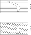
- FIG. 8 shows an alternate pattern where the ribs are essentially diagonal or helical in the same direction off axial as is the footprint chord.
- the diagonal/spiral form balances cost and ease of manufacture against aerodynamic performance.
- FIG. 9 shows an alternate pattern where the ribs are circumferential.
- ease and low cost of manufacture may be favored over aerodynamic performance.
- the CMC ribs may be atop a monolithic ceramic (or a randomly filled/reinforced ceramic) instead of a CMC.
- Other fiber composite (fibers in matrix) variations involve use of organic matrix composite (OMC) substrates and ribs.
- OMC organic matrix composite
- first, second, and the like in the following claims is for differentiation within the claim only and does not necessarily indicate relative or absolute importance or temporal order. Similarly, the identification in a claim of one element as “first” (or the like) does not preclude such "first” element from identifying an element that is referred to as “second” (or the like) in another claim or in the description.
Landscapes
- Engineering & Computer Science (AREA)
- Mechanical Engineering (AREA)
- General Engineering & Computer Science (AREA)
- Chemical & Material Sciences (AREA)
- Materials Engineering (AREA)
- Physics & Mathematics (AREA)
- Fluid Mechanics (AREA)
- Composite Materials (AREA)
- Ceramic Engineering (AREA)
- Turbine Rotor Nozzle Sealing (AREA)
- Laminated Bodies (AREA)
Abstract
Description
- The disclosure relates to turbomachinery. More particularly, the disclosure relates to ceramic and ceramic matrix composite (CMC) components along the gaspath of turbine sections of such turbomachinery.
- CMC has been proposed for wide use in hot sections of gas turbine engines (broadly inclusive of engines used in propulsion via thrust, other propulsive engines, industrial gas turbines, and the like). Particular structures proposed for CMC use include turbine blades and vanes (e.g., United States Patent Application Publication
20100189556A1 , Propheter-Hinckley et al., July 29, 2010, "Segmented Ceramic Matrix Composite Turbine Airfoil Component"), combustor components (e.g., United States Patent Application Publication20170314785A1, Vargas, November 2, 2017 , "Ceramic and Ceramic Matrix Composite Attachment Methods and Systems"), and blade outer air seals (BOAS) (e.g., United States Patent Application Publication20160215645A1, McCaffrey, July 28, 2016 , "Blade Outer Air Seal Made of Ceramic Matrix Composite"). - United States Patent Application
15/354,083, Propheter-Hinckley et al., November 17, 2016 - Separately, in the field of metallic blades, United States Patent
9,109,452, Martin et al., August 18, 2015 20170234134A1, Bunker, August 17, 2017 , "Riblets for a Flowpath Surface of a Turbomachine", also discloses airfoil surface features. - Also, in the field of blade outer air seals (BOAS), United States Patent
7,600,968, Nelson et al., October 13, 2009 , "Pattern for the Surface of a Turbine Shroud" discloses various patterns of ribs along the inner diameter (ID) surface of a BOAS. - One aspect of the disclosure involves a turbomachine airfoil element comprising: a substrate defining an airfoil having a pressure side and a suction side; and a plurality of fiber composite ribs along the pressure side.
- An embodiment of the foregoing may additionally and/or alternatively include the turbomachine airfoil element being a blade having a free tip.
- A further embodiment of any of the foregoing embodiments may additionally and/or alternatively include the ribs converging toward each other from upstream to downstream (i.e. from the leading edge to the trailing edge).
- A further embodiment of any of the foregoing embodiments may additionally and/or alternatively include the ribs comprising a plurality of short ribs alternating with a plurality of long ribs.
- A further embodiment of any of the foregoing embodiments may additionally and/or alternatively include the ribs shifting tipward (or radially outward) from upstream to downstream.
- A further embodiment of any of the foregoing embodiments may additionally and/or alternatively include the ribs being only along an outboard half of the pressure side.
- A further embodiment of any of the foregoing embodiments may additionally and/or alternatively include the turbomachine airfoil element being non-hollow.
- A further embodiment of any of the foregoing embodiments may additionally and/or alternatively include the turbomachine airfoil element lacking internal cooling passageways.
- A further embodiment of any of the foregoing embodiments may additionally and/or alternatively include the turbomachine airfoil element lacking film cooling holes adjacent the plurality of ribs.
- A further embodiment of any of the foregoing embodiments may additionally and/or alternatively include each rib comprising a stack of tapes, the tapes each comprising a plurality of fiber bundles.
- A further embodiment of any of the foregoing embodiments may additionally and/or alternatively include the fiber composite ribs being ceramic matrix composite (CMC).
- A further embodiment of any of the foregoing embodiments may additionally and/or alternatively include the substrate comprising a CMC.
- A further embodiment of any of the foregoing embodiments may additionally and/or alternatively include the CMC of the substrate and the CMC of the ribs each comprising: a silicon-based matrix; and silicon-based fibers embedded in the matrix.
- A further embodiment of any of the foregoing embodiments may additionally and/or alternatively include the CMC comprising: a silicon-based matrix; and silicon-based fibers embedded in the matrix.
- A further embodiment of any of the foregoing embodiments may additionally and/or alternatively include a coating over the ribs and extending beyond the ribs.
- A further embodiment of any of the foregoing embodiments may additionally and/or alternatively include a turbomachine including a stage of the turbomachine airfoil elements, the turbomachine airfoil elements being blades, and the turbomachine further comprising a blade outer airseal adjacent tips of the blades.
- A further embodiment of any of the foregoing embodiments may additionally and/or alternatively include a method for using the turbomachine airfoil element. The method comprises: running a stage of said airfoil elements forming a blade stage; and the ribs diverting gas flow along the pressure sides relatively toward the respective trailing edges and away from the respective tips.
- Another aspect of the disclosure, which the Applicant expressly reserves the right to claim independently, involves a gas turbine engine comprising: a gaspath, a component along the gaspath comprising: a substrate; and a plurality of fiber composite ribs along the gaspath.
- A further embodiment of any of the foregoing embodiments may additionally and/or alternatively include the component being a blade outer airseal and the ribs being along an ID (inner diameter) face of the substrate.
- Another aspect of the disclosure, which the Applicant expressly reserves the right to claim independently, involves a method for guiding gas flow along a surface of a component of a turbomachine, the method comprising: providing a plurality of fiber composite ribs along the surface parallel to a desired direction of the gas flow.
- The ribs may have any of the features discussed above.
- The details of one or more embodiments are set forth in the accompanying drawings and the description below. Other features, objects, and advantages will be apparent from the description and drawings, and from the claims.
-
-
FIG. 1 is a partially schematic half-sectional (central longitudinal) view of a gas turbine engine. -
FIG. 2 is a view of a blade of the engine. -
FIG. 3 is a partial sectional view of a pressure side wall of the blade taken transverse to a surface rib. -
FIG. 4 is a partial sectional view of a pressure side wall of the blade taken along a surface rib. -
FIG. 5 is a view of a prior art blade. -
FIG. 6 is a partial view of a ribbed blade outer airseal (BOAS) showing sweep by two blade airfoils of a stage of blades. -
FIG. 7 is a schematic view of the relationship between blade airfoils and pattern of BOAS ribs for the BOAS ofFIG. 6 . -
FIG. 8 is a schematic view of the relationship between blade airfoils and an alternate pattern of BOAS ribs. -
FIG. 9 is a schematic view of the relationship between blade airfoils and an alternate pattern of BOAS ribs. - Like reference numbers and designations in the various drawings indicate like elements.
-
FIG. 1 is a schematic illustration of agas turbine engine 10. The illustrated engine is a turbofan used to produce propulsive thrust in aerospace applications. Broadly, relevant gas turbine engines may also include turbojets, turboprops, turboshafts, industrial gas turbines (IGT), and the like. For purposes of illustration, outer aerodynamic cases are not shown. The gas turbine engine has a centrallongitudinal axis 500. The gas turbine engine generally has afan section 12 through which aninlet flow 520 of ambient air is propelled by afan 14, acompressor 16 for pressurizing the air 520-1 received from thefan 14, and acombustor 18 wherein the compressed air is mixed with fuel and ignited for generating combustion gases. Theinlet flow 520 splits into a first or core portion 520-1 flowing along the gaspath (core flowpath) 510 and a bypass portion 520-2 flowing along abypass flowpath 512. The illustratedengine 10 and gross features are based on a particular configuration. Nevertheless, the teachings herein may be applied to other general engine configurations and other particular component configurations. - The
gas turbine engine 10 further comprises aturbine 20 for extracting energy from the combustion gases. Fuel is injected into thecombustor 18 of thegas turbine engine 10 for mixing with the compressed air from thecompressor 16 and ignition of the resultant mixture. Thefan 14,compressor 16,combustor 18, andturbine 20 are typically all concentric about a centrallongitudinal axis 500 of thegas turbine engine 10. - Depending upon the implementation, the compressor and turbine may each contain multiple sections. Each section includes one or more stages of rotor blades interspersed with one or more stages of stator vanes. The exemplary configuration has two compressor sections and two turbine sections. From upstream to downstream along the
gaspath 510, these include a Low Pressure Compressor section (LPC) 16-1, a High Pressure Compressor section (HPC) 16-2, a High Pressure Turbine section (HPT) 20-2, and a Low Pressure Turbine section (LPT) 20-1. The exemplary rotors of the LPC and LPT are formed to rotate as a first unit or low pressure spool with the LPT driving the LPC. Similarly, the HPT and HPC rotors are arranged as a high pressure spool. The fan may be driven by the low pressure spool either directly or via areduction gearbox 30. Other configurations are, however, known. - The exemplary engine comprises a
fan case 32 and acore case 34. The core case has sections along the corresponding sections of the engine core (e.g. an LPC case section, an HPC case section, a HPT case section, and an LPT case section). - Each of the LPC, HPC, HPT, and LPT sections has several stages of blades of the associated rotor. Interspersed with the blades are stages of stator vanes.
-
FIG. 5 shows a prior art CMC (e.g., silicon carbide fibers in silicon carbide matrix)turbine blade 101 having anairfoil 102 extending from aninboard end 104 at aplatform 106 to anoutboard end 108 at atip 110. The airfoil exterior (gaspath-facing) surface extends from an upstreamleading edge 112 to adownstream trailing edge 114 and has apressure side 116 and asuction side 118. Aprotuberant attachment root 120 depends from the underside of theplatform 106 for attaching the blade to a disk. Alternative blade configurations are integrally formed with the disk (integrally bladed rotors (IBR) or blisks). The exemplary blade lacks internal cooling air passages, generally, and film cooling holes to the airfoil surface, particularly. This highlights one potential area of advantage of CMC blades relative to metallic blades. Use of cooling air creates several inefficiencies. First, it cools and dilutes the combustion gases, thereby reducing the amount of energy that could be extracted by the turbine. Second, diversion of cooling air reduces the amount of air that could be driven through the bypass flowpath, thereby further reducing thrust. Nevertheless, the blades may have internal cooling passages and there may be film cooling. - In one particular group of examples, the film cooling holes could be positioned between the ribs. This may counter vortex formation.
- In operation, as the blade rotates, the centrifugal action causes the gas flow 520-1A (a portion of the core flow 520-1) along the pressure side to radially outwardly diverge and form a leakage flow over the tip toward the suction side (e.g., between the tip and a blade outer air seal (BOAS)). This reduces efficiency of energy extraction from the gas.
-
FIG. 2 shows a modifiedblade 100 having a radially or spanwise arrayed plurality ofsurface ribs upstream end 142 to a trailing/downstream end 144. The leading ends are all close to the leading edge 112 (e.g., within 10% of the local distance along the pressure side from the leading edge to the trailing edge). The ribs are oriented to guide the gas flow 520-1A to reduce or minimize leakage over the tip. The spanwise spacing between any given two ribs generally converges from upstream to downstream. Given this convergence, the exemplary embodiment has alternating essentiallyfull length ribs shorter ribs ends 144 terminating well short of the trailing edge (e.g., at least 25% or 35% shy of the trailing edge)). This alternating/interdigitated arrangement of ribs allows for sufficient density of ribs near the leading edge to provide a desired guidance of the flow while not interfering with that flow guidance near the trailing edge. For example, if the density got too high near the trailing edge, the flow would tend to merely pass over the ribs. Near the tip, the ribs are close to parallel to the tip. Near the root, the ribs radially diverge toward the tip from upstream to downstream. The use of alternating shorter ribs also reduces rotating mass relative to hypothetical use of only full-length ribs. - In further variations, the ribs may have non-uniform cross-section between the leading/
upstream end 142 and the trailing/downstream end 144. For example, a cross-section near the leading/upstream end 142 may be greater than that near the trailing/downstream end 144 (e.g., wider or taller). The greater cross-section upstream may allow for greater flow turning and handling greater stresses. The taper downstream may be for aerodynamic purposes such as avoiding vortex formation. - In yet further variations, the leading end of the ribs may be aerodynamically shaped for minimizing losses.
- The exemplary ribs are located along an outboard portion of the airfoil (e.g., along an outboard half). This may have several advantages. First, is simple reduction of cost relative to having ribs along the entire span. Second, is it limits risk of creating turbulence along the inboard portion of the airfoil (whereas turbulence may otherwise be present near the tip). Also, the added rotating weight of ribs on the inboard portion is avoided. However, in further variations, the ribs can be located along an inboard portion and/or along a platform surface.
- As is noted above, the illustrated example lacks any surface film cooling holes. Thus, unlike certain metallic blades, the surface ribs in the example are not associated with any discharge from film cooling holes. Nevertheless, this does not preclude the ribs being used on film-cooled embodiments.
-
FIG. 3 is a partial sectional view of the airfoil taken transverse to arib 140. This shows the blade along the airfoil as comprising aCMC substrate 160 of a main body of the airfoil; acore substrate 162 of the rib atop asurface 164 of thesubstrate 160, and acoating 166. The exemplary coating is a two layer coating havingfirst layer 168 and asecond layer 170. An exemplary second layer is an environmental barrier coating (EBC - typically a ceramic) and an exemplary first layer is a bond coat to improve adhesion of the EBC to the CMC substrate. - Exemplary EBC and bond coats are disclosed in United States Patent Application Publication
20060280952A1 (the '952 publication), of Hazel et al., published December 14, 2006, and entitled "Bond coat for corrosion resistant EBC for silicon-containing substrate and processes for preparing same". The '952 publication discloses silicon-containing bond coats and silicide-containing bond coats. An exemplary bond coat is applied by spray or vapor deposition. Exemplary silicon, silicate, or silica bond coats may comprise one or more layers formed from rare earth silicates such as a mullite layer, a mullite-alkaline earth aluminosilicate mixture layer, an yttrium monosilicate layer, an ytterbium doped yttrium disilicate layer, a barium strontium aluminosilicate layer, and the like. The application technique may tailored so that at the edges of the ribs there is a sufficiently gradual transition to prevent EBC spallation while still having a desired flow redirection. One approach is to have a thick bond coat for improved elasticity. An exemplary EBC is one or more ceramic layers such as stabilized zirconias or alumina, applied by spray or vapor deposition. - The exemplary configuration forms the CMC substrate of interwoven
tapes 180 of fiber (e.g., ceramic) bundles 182. The exemplary schematic illustration has six fiber bundles per tape. For purposes of illustration, these are shown in a simple weave of tapes 180-1 and 180-2 in respective alternating orthogonal directions.FIG. 3 also shows aceramic matrix 172 encapsulating the fibers of the substrate and rib. - The exemplary rib is also made out of
similar tapes 180. For purposes of illustration of the interlayering of tapes, each tape is shown with distinct hatching. The exemplary lay-up includes a single central tape. Two tapes form a layer on top and then progressively more tapes form further layers. This allows the size of the rib to gradually taper. -
FIG. 4 shows one of theends tapes 180 are progressively longer from the base layer outward. This provides a gradual taper at the ends. The side and end tapers avoid sharp corners that would produce notch stress in thecoating 166. - In terms of exemplary dimensions,
FIG. 3 shows exemplary rib heights HR and widths WR as projected through the coating. Alternative dimensional characterizations may involve the height and width of the CMC substrate (e.g., all the bundles that form the rib such as those that are not part of the normal weave or other layup of the blade substrate). These height and width dimensions are shown as HB and WB. With a relatively even coating thickness, HB and HR will be about the same but WB will be smaller than WR. Exemplary rib heights HR are 0.005 inch to 0.020 inch (0.13 millimeter to 0.51 millimeter), more narrowly 0.20 millimeter to 0.40 millimeter for typical sizes of aero engines or in the range of 0.20 millimeter to 1.2 millimeter for industrial gas turbines. Exemplary WB is 0.005 inch to 0.015 inch (0.13 millimeter to 0.38 millimeter), more broadly 0.13 millimeter to 0.50 millimeter for aero engines with 0.13 millimeter to 3.0 millimeter for industrial gas turbines. Exemplary WR is 1.25 to 2.0 times WB, more broadly 1.0 to 5.0. Rib length may similarly be measured with terminal locations for lengths LR and LB shown inFIG. 4 . - An exemplary process of engineering the blade may start from a baseline blade without ribs. It may include an iterative computational fluid dynamics (CFD) simulation. There are a broad range of options for which parameters of the optimization are fixed to begin with and which are varied/optimized. Such options may reflect designer experience. These parameters include the height and width of ribs, the streamwise locations at which they begin and end, the portion of the airfoil along which they are arranged, and the amount of redirection of the flow.
- In one example only the amount of redirection is optimized. Consider that ribs parallel to the core flowpath (e.g., a rib that starts and ends at X% of the local airfoil span) may represent too much redirection and produces turbulence/losses. The simulation may work from that value toward stability or from the baseline toward that. Assume that the baseline (ribless) simulation has a streamline that starts at 70% span at the leading edge just leaking over the tip at the trailing edge. One might start the simulation with an increment such that a rib at 70% span near the leading edge is directed toward a 90% span location at the trailing edge. The rib may continuously progressively diverge from the baseline streamline. For purposes of example, it is assumed that the rib density is initially set (either in absolute terms (e.g. ribs starting every 3.0 millimeter of span from 60% span outward) or relative terms (e.g. ribs starting every 4% of span from 60% span outward)). Iterations may increase the amount of redirection until negative returns (e.g., turbulence above a tolerable threshold is observed) are encountered. The may be a zeroing in in terms of changing the increment and /or backing off to find an optimum. Other parameters may similarly be iteratively optimized.
- Thus, an exemplary process of manufacture may be implemented as a modification of a baseline process (e.g., see the '083 application) for manufacturing a baseline component (i.e., one without the subject ribs but which is to be replaced by the modified component having the ribs). Some processes may involve forming the ribs as part of the basic structure of the substrate (e.g., wherein the rib tapes or individual bundles become interwoven with the rest of the substrate). Others involve separate application. One group of separate application techniques involves essentially laying up the fibers of the substrate and then applying the fibers of the ribs. This may be done before matrix infiltration of the substrate or after infiltration of the substrate. In the latter situation, the tapes or bundles of the ribs could be pre-infiltrated with matrix material or a separate subsequent infiltration step could occur. Another possible process involves modifying the die/mold used for the substrate layup to include grooves corresponding to the ribs. The rib bundles or tapes could then be inserted into the grooves and then the substrate laid-up as in the baseline.
- Thus, one particular example of a process may involve lay-up of the fiber bundles/tapes in a die. The matrix is then infiltrated into the lay-up (e.g., via melt infiltration). After solidification (e.g., cooling), there may be a machining and then coating.
-
FIG. 6 shows aBOAS 200. The exemplary BOAS is circumferentially segmented. Each segment has a substrate 204 (e.g., metallic, ceramic, or hybrid metallic/ceramic) with mounting features for mounting to acase 206. Aceramic layer 208 atop the substrate may be formed by monolithic ceramic or CMC.CMC ribs 210 may be formed similarly to the blade CMC ribs. - The exemplary BOAS segment has a forward/upstream/leading
end 220 and an aft/downstream/trailingend 222 and first 224 and second 226 circumferential ends (FIG. 7). FIG. 7 shows the footprint of the airfoil at the tip. Exemplary rib planform bears a relationship to the airfoil tip footprint. In aregion 230 near the trailing end, swept by a trailing portion of the airfoil tip footprint, the rib planform is generally close to an orientation of the suction side of the footprint. This may streamline gas flow along the tip for vortex reduction near the airfoil trailing portion. However, in aregion 232 near the leading end, the shaped to minimize airfoil turning loss. In other variations, the leading end may be curved more aggressively. -
FIG. 8 shows an alternate pattern where the ribs are essentially diagonal or helical in the same direction off axial as is the footprint chord. In this example, the diagonal/spiral form balances cost and ease of manufacture against aerodynamic performance. -
FIG. 9 shows an alternate pattern where the ribs are circumferential. In this example, ease and low cost of manufacture may be favored over aerodynamic performance. - In further variations, the CMC ribs may be atop a monolithic ceramic (or a randomly filled/reinforced ceramic) instead of a CMC. Other fiber composite (fibers in matrix) variations involve use of organic matrix composite (OMC) substrates and ribs.
- The use of "first", "second", and the like in the following claims is for differentiation within the claim only and does not necessarily indicate relative or absolute importance or temporal order. Similarly, the identification in a claim of one element as "first" (or the like) does not preclude such "first" element from identifying an element that is referred to as "second" (or the like) in another claim or in the description.
- Where a measure is given in English units followed by a parenthetical containing SI or other units, the parenthetical's units are a conversion and should not imply a degree of precision not found in the English units.
- One or more embodiments have been described. Nevertheless, it will be understood that various modifications may be made. For example, when applied to an existing baseline configuration, details of such baseline may influence details of particular implementations. Accordingly, other embodiments are within the scope of the following claims.
Claims (15)
- A turbomachine airfoil element (100) comprising:a substrate (160) defining an airfoil having a pressure side and a suction side; anda plurality of fiber composite ribs (140;140A-E) along the pressure side.
- The turbomachine airfoil element (100) of claim 1 being a blade having a free tip.
- The turbomachine airfoil element (100) of any preceding claim wherein the ribs (140;140A-E) converge toward each other from upstream to downstream.
- The turbomachine airfoil element (100) of any preceding claim wherein the ribs (140;140A-E) comprise a plurality of shorter ribs (140B,140D) alternating with a plurality of longer ribs (140A,140C,140E).
- The turbomachine airfoil element (100) of any preceding claim wherein the ribs (140;140A-E) shift tipward from upstream to downstream.
- The turbomachine airfoil element (100) of any preceding claim wherein the ribs (140;140A-E) are only along an outboard half of the pressure side.
- The turbomachine airfoil element (100) of any preceding claim being non-hollow.
- The turbomachine airfoil element (100) of any preceding claim wherein:the turbomachine airfoil element lacks internal cooling passageways; and/orlacks film cooling holes adjacent the plurality of ribs (140;140A-E).
- The turbomachine airfoil element (100) of any preceding claim wherein each rib (140;140A-E) comprises a stack of tapes (180;180-1,180-2), the tapes (180;180-1,180-2) each comprising a plurality of fiber bundles (182).
- The turbomachine airfoil element (100) of any preceding claim wherein the fiber composite ribs (140;140A-E) are ceramic matrix composite (CMC).
- The turbomachine airfoil element (100) of any preceding claim wherein the substrate (160) comprises a CMC.
- The turbomachine airfoil element (100) of claim 10 or 11 wherein the CMC of the ribs (140;140A-E) and/or the CMC of the substrate (160) comprises:a silicon-based matrix (172); andsilicon-based fibers embedded in the matrix (172).
- The turbomachine airfoil element (100) of any preceding claim further comprising a coating (166) over the ribs (140;140A-E) and extending beyond the ribs (140;140A-E).
- A turbomachine (10) including:a stage of the turbomachine airfoil elements (100) of any preceding claim, the turbomachine airfoil elements (100) being blades (100); anda blade outer airseal (200) adjacent tips of the blades (100).
- A method for using the turbomachine airfoil element (100) of any of claims 1 to 13, the method comprising:running a stage of said airfoil elements forming a blade stage; andthe ribs (140;140A-E) diverting gas flow (520-1A) along the pressure sides relatively toward the respective trailing edges and away from the respective tips.
Applications Claiming Priority (1)
| Application Number | Priority Date | Filing Date | Title |
|---|---|---|---|
| US15/841,627 US10605087B2 (en) | 2017-12-14 | 2017-12-14 | CMC component with flowpath surface ribs |
Publications (3)
| Publication Number | Publication Date |
|---|---|
| EP3498976A2 true EP3498976A2 (en) | 2019-06-19 |
| EP3498976A3 EP3498976A3 (en) | 2019-06-26 |
| EP3498976B1 EP3498976B1 (en) | 2021-09-15 |
Family
ID=64665673
Family Applications (1)
| Application Number | Title | Priority Date | Filing Date |
|---|---|---|---|
| EP18212690.4A Active EP3498976B1 (en) | 2017-12-14 | 2018-12-14 | Turbomachine airfoil with flowpath surface ribs |
Country Status (2)
| Country | Link |
|---|---|
| US (1) | US10605087B2 (en) |
| EP (1) | EP3498976B1 (en) |
Families Citing this family (11)
| Publication number | Priority date | Publication date | Assignee | Title |
|---|---|---|---|---|
| US10738628B2 (en) * | 2018-05-25 | 2020-08-11 | General Electric Company | Joint for band features on turbine nozzle and fabrication |
| EP3823775A4 (en) * | 2018-07-18 | 2022-03-23 | Poly6 Technologies, Inc. | Articles and methods of manufacture |
| EP3608505B1 (en) | 2018-08-08 | 2021-06-23 | General Electric Company | Turbine incorporating endwall fences |
| BE1026579B1 (en) * | 2018-08-31 | 2020-03-30 | Safran Aero Boosters Sa | PROTUBERANCE VANE FOR TURBOMACHINE COMPRESSOR |
| US20220186742A1 (en) * | 2019-05-21 | 2022-06-16 | Mitsubishi Electric Corporation | Axial fan, air-sending device, and refrigeration cycle apparatus |
| AT523439A1 (en) * | 2020-01-14 | 2021-07-15 | Peter Leitl | Method for the production of an object provided with riblets on and / or in the surface and an object produced therewith |
| IT202100002240A1 (en) | 2021-02-02 | 2022-08-02 | Gen Electric | TURBINE ENGINE WITH REDUCED TRANSVERSE FLOW VANES |
| US11719103B1 (en) * | 2022-04-07 | 2023-08-08 | General Electric Company | Components having composite laminate with co-cured chopped fibers |
| US11834967B1 (en) * | 2022-05-13 | 2023-12-05 | Rtx Corporation | Liner for anti-rotation tab and ceramic component |
| CN116538144B (en) * | 2023-04-13 | 2025-12-09 | 中国航空发动机研究院 | Hollow guide vane of fan, manufacturing method and aeroengine |
| US20250059894A1 (en) * | 2023-08-16 | 2025-02-20 | General Electric Company | Turbine engine and a composite airfoil assembly thereof |
Citations (7)
| Publication number | Priority date | Publication date | Assignee | Title |
|---|---|---|---|---|
| US20060280952A1 (en) | 2005-06-13 | 2006-12-14 | Hazel Brian T | Bond coat for corrosion resistant EBC for silicon-containing substrate and processes for preparing same |
| US7600968B2 (en) | 2004-11-24 | 2009-10-13 | General Electric Company | Pattern for the surface of a turbine shroud |
| US20100189556A1 (en) | 2009-01-28 | 2010-07-29 | United Technologies Corporation | Segmented ceramic matrix composite turbine airfoil component |
| US9109452B2 (en) | 2012-06-05 | 2015-08-18 | United Technologies Corporation | Vortex generators for improved film effectiveness |
| US20160215645A1 (en) | 2013-08-29 | 2016-07-28 | United Technologies Corporation | Blade outer air seal made of ceramic matrix composite |
| US20170234134A1 (en) | 2016-02-12 | 2017-08-17 | General Electric Company | Riblets For A Flowpath Surface Of A Turbomachine |
| US20170314785A1 (en) | 2016-04-28 | 2017-11-02 | United Technologies Corporation | Ceramic and Ceramic Matrix Composite Attachment Methods and Systems |
Family Cites Families (32)
| Publication number | Priority date | Publication date | Assignee | Title |
|---|---|---|---|---|
| US1022203A (en) * | 1911-07-05 | 1912-04-02 | John F Nettle | Propeller. |
| DE833100C (en) * | 1950-08-23 | 1952-03-03 | Inconex Handelsgesellschaft M | Turbo compressor blade with boundary layer fences |
| US3012709A (en) * | 1955-05-18 | 1961-12-12 | Daimler Benz Ag | Blade for axial compressors |
| BE638547A (en) * | 1962-10-29 | 1900-01-01 | ||
| US3706512A (en) * | 1970-11-16 | 1972-12-19 | United Aircraft Canada | Compressor blades |
| US4128363A (en) * | 1975-04-30 | 1978-12-05 | Kabushiki Kaisha Toyota Chuo Kenkyusho | Axial flow fan |
| JPS5377321A (en) * | 1976-12-20 | 1978-07-08 | Toyota Central Res & Dev Lab Inc | Axial-flow fan with supplementary blade |
| JPS5377320A (en) * | 1976-12-20 | 1978-07-08 | Toyota Central Res & Dev Lab Inc | Axial-flow fan with supplementary blade |
| US4108573A (en) * | 1977-01-26 | 1978-08-22 | Westinghouse Electric Corp. | Vibratory tuning of rotatable blades for elastic fluid machines |
| GB2017228B (en) * | 1977-07-14 | 1982-05-06 | Pratt & Witney Aircraft Of Can | Shroud for a turbine rotor |
| DE9013099U1 (en) * | 1990-09-14 | 1991-11-07 | Moser, Josef, 8058 Pretzen | rotor |
| US5368508A (en) * | 1993-06-08 | 1994-11-29 | Whittington; Burl D. | Marine propeller with transversal converging ribs |
| US5525038A (en) * | 1994-11-04 | 1996-06-11 | United Technologies Corporation | Rotor airfoils to control tip leakage flows |
| EP0962874A1 (en) * | 1998-06-04 | 1999-12-08 | Asea Brown Boveri AG | Method for designing a flow device |
| US6284390B1 (en) * | 1998-06-12 | 2001-09-04 | United Technologies Corporation | Thermal barrier coating system utilizing localized bond coat and article having the same |
| US6589600B1 (en) * | 1999-06-30 | 2003-07-08 | General Electric Company | Turbine engine component having enhanced heat transfer characteristics and method for forming same |
| US6612808B2 (en) * | 2001-11-29 | 2003-09-02 | General Electric Company | Article wall with interrupted ribbed heat transfer surface |
| US20050091848A1 (en) * | 2003-11-03 | 2005-05-05 | Nenov Krassimir P. | Turbine blade and a method of manufacturing and repairing a turbine blade |
| GB2411440B (en) * | 2004-02-24 | 2006-08-16 | Rolls Royce Plc | Gas turbine nozzle guide vane |
| US7153096B2 (en) * | 2004-12-02 | 2006-12-26 | Siemens Power Generation, Inc. | Stacked laminate CMC turbine vane |
| US7435058B2 (en) * | 2005-01-18 | 2008-10-14 | Siemens Power Generation, Inc. | Ceramic matrix composite vane with chordwise stiffener |
| EP1788255A1 (en) * | 2005-11-16 | 2007-05-23 | Siemens Aktiengesellschaft | Impeller of radial compressor |
| US20160052621A1 (en) * | 2009-07-10 | 2016-02-25 | Peter Ireland | Energy efficiency improvements for turbomachinery |
| US9228445B2 (en) * | 2010-12-23 | 2016-01-05 | General Electric Company | Turbine airfoil components containing ceramic-based materials and processes therefor |
| US8460779B2 (en) * | 2011-03-30 | 2013-06-11 | General Electric Company | Microstructures for reducing noise of a fluid dynamic structure |
| EP2532510B1 (en) * | 2011-06-07 | 2016-11-16 | Siemens Aktiengesellschaft | Method of modifying the surface shape of a wind turbine rotor blade |
| US9091176B2 (en) * | 2012-06-05 | 2015-07-28 | United Technologies Corporation | Turbomachinery component cooling scheme |
| ITCO20130024A1 (en) * | 2013-06-13 | 2014-12-14 | Nuovo Pignone Srl | COMPRESSOR IMPELLERS |
| RU2016134446A (en) | 2014-02-25 | 2018-03-29 | Сименс Акциенгезелльшафт | THERMAL BARRIER COATING OF A TURBINE COMPONENT WITH MATERIAL PROPERTIES VARIABLE DEPTH |
| US8939705B1 (en) * | 2014-02-25 | 2015-01-27 | Siemens Energy, Inc. | Turbine abradable layer with progressive wear zone multi depth grooves |
| JP6213668B2 (en) * | 2014-04-22 | 2017-10-18 | 日本電気株式会社 | Semiconductor device, infrared imaging device including the semiconductor device, and method for controlling the semiconductor device |
| US9777635B2 (en) * | 2014-12-31 | 2017-10-03 | General Electric Company | Engine component |
-
2017
- 2017-12-14 US US15/841,627 patent/US10605087B2/en active Active
-
2018
- 2018-12-14 EP EP18212690.4A patent/EP3498976B1/en active Active
Patent Citations (7)
| Publication number | Priority date | Publication date | Assignee | Title |
|---|---|---|---|---|
| US7600968B2 (en) | 2004-11-24 | 2009-10-13 | General Electric Company | Pattern for the surface of a turbine shroud |
| US20060280952A1 (en) | 2005-06-13 | 2006-12-14 | Hazel Brian T | Bond coat for corrosion resistant EBC for silicon-containing substrate and processes for preparing same |
| US20100189556A1 (en) | 2009-01-28 | 2010-07-29 | United Technologies Corporation | Segmented ceramic matrix composite turbine airfoil component |
| US9109452B2 (en) | 2012-06-05 | 2015-08-18 | United Technologies Corporation | Vortex generators for improved film effectiveness |
| US20160215645A1 (en) | 2013-08-29 | 2016-07-28 | United Technologies Corporation | Blade outer air seal made of ceramic matrix composite |
| US20170234134A1 (en) | 2016-02-12 | 2017-08-17 | General Electric Company | Riblets For A Flowpath Surface Of A Turbomachine |
| US20170314785A1 (en) | 2016-04-28 | 2017-11-02 | United Technologies Corporation | Ceramic and Ceramic Matrix Composite Attachment Methods and Systems |
Also Published As
| Publication number | Publication date |
|---|---|
| EP3498976A3 (en) | 2019-06-26 |
| EP3498976B1 (en) | 2021-09-15 |
| US10605087B2 (en) | 2020-03-31 |
| US20190186271A1 (en) | 2019-06-20 |
Similar Documents
| Publication | Publication Date | Title |
|---|---|---|
| EP3498976B1 (en) | Turbomachine airfoil with flowpath surface ribs | |
| EP2815078B1 (en) | Gas turbine engine component and corresponding combustor assembly | |
| US8572983B2 (en) | Gas turbine engine component with impingement and diffusive cooling | |
| EP2825733B1 (en) | Airfoil and corresponding rotor blade for a gas turbine engine | |
| US12345177B2 (en) | Turbine engine with composite airfoils | |
| CN106930837B (en) | Thermal Management of CMC Articles with Membrane Pores | |
| EP3043026B1 (en) | High lift airfoil and corresponding method of vectoring cooling air | |
| US12410753B2 (en) | Gas turbine engine | |
| WO2012016789A1 (en) | Turbine airfoil and method for thermal barrier coating | |
| EP3460191A1 (en) | Gas turbine engine component with cooling holes having variable roughness | |
| WO2013165518A9 (en) | Gas turbine engine component with cusped, lobed cooling hole | |
| US20200141247A1 (en) | Component for a turbine engine with a film hole | |
| US12467370B2 (en) | Turbine engine with composite airfoils | |
| US20250198290A1 (en) | Gas turbine engine | |
| WO2013172903A2 (en) | Tapered thermal coating for airfoil | |
| US12503980B2 (en) | Gas turbine engine | |
| US12571404B2 (en) | Turbine engine with composite airfoils | |
| US12331661B2 (en) | Turbine engine with composite airfoils | |
| US20250257694A1 (en) | Gas turbine engine | |
| US20250215823A1 (en) | Gas turbine engine | |
| US20250179923A1 (en) | Gas turbine engine |
Legal Events
| Date | Code | Title | Description |
|---|---|---|---|
| PUAI | Public reference made under article 153(3) epc to a published international application that has entered the european phase |
Free format text: ORIGINAL CODE: 0009012 |
|
| STAA | Information on the status of an ep patent application or granted ep patent |
Free format text: STATUS: THE APPLICATION HAS BEEN PUBLISHED |
|
| PUAL | Search report despatched |
Free format text: ORIGINAL CODE: 0009013 |
|
| AK | Designated contracting states |
Kind code of ref document: A2 Designated state(s): AL AT BE BG CH CY CZ DE DK EE ES FI FR GB GR HR HU IE IS IT LI LT LU LV MC MK MT NL NO PL PT RO RS SE SI SK SM TR |
|
| AX | Request for extension of the european patent |
Extension state: BA ME |
|
| AK | Designated contracting states |
Kind code of ref document: A3 Designated state(s): AL AT BE BG CH CY CZ DE DK EE ES FI FR GB GR HR HU IE IS IT LI LT LU LV MC MK MT NL NO PL PT RO RS SE SI SK SM TR |
|
| AX | Request for extension of the european patent |
Extension state: BA ME |
|
| RIC1 | Information provided on ipc code assigned before grant |
Ipc: F01D 11/14 20060101ALI20190520BHEP Ipc: F01D 5/28 20060101AFI20190520BHEP Ipc: F01D 5/14 20060101ALI20190520BHEP Ipc: C04B 35/80 20060101ALI20190520BHEP |
|
| STAA | Information on the status of an ep patent application or granted ep patent |
Free format text: STATUS: REQUEST FOR EXAMINATION WAS MADE |
|
| 17P | Request for examination filed |
Effective date: 20200102 |
|
| RBV | Designated contracting states (corrected) |
Designated state(s): AL AT BE BG CH CY CZ DE DK EE ES FI FR GB GR HR HU IE IS IT LI LT LU LV MC MK MT NL NO PL PT RO RS SE SI SK SM TR |
|
| STAA | Information on the status of an ep patent application or granted ep patent |
Free format text: STATUS: EXAMINATION IS IN PROGRESS |
|
| 17Q | First examination report despatched |
Effective date: 20200727 |
|
| RAP1 | Party data changed (applicant data changed or rights of an application transferred) |
Owner name: RAYTHEON TECHNOLOGIES CORPORATION |
|
| GRAP | Despatch of communication of intention to grant a patent |
Free format text: ORIGINAL CODE: EPIDOSNIGR1 |
|
| STAA | Information on the status of an ep patent application or granted ep patent |
Free format text: STATUS: GRANT OF PATENT IS INTENDED |
|
| INTG | Intention to grant announced |
Effective date: 20210401 |
|
| GRAS | Grant fee paid |
Free format text: ORIGINAL CODE: EPIDOSNIGR3 |
|
| GRAA | (expected) grant |
Free format text: ORIGINAL CODE: 0009210 |
|
| STAA | Information on the status of an ep patent application or granted ep patent |
Free format text: STATUS: THE PATENT HAS BEEN GRANTED |
|
| AK | Designated contracting states |
Kind code of ref document: B1 Designated state(s): AL AT BE BG CH CY CZ DE DK EE ES FI FR GB GR HR HU IE IS IT LI LT LU LV MC MK MT NL NO PL PT RO RS SE SI SK SM TR |
|
| REG | Reference to a national code |
Ref country code: CH Ref legal event code: EP |
|
| REG | Reference to a national code |
Ref country code: DE Ref legal event code: R096 Ref document number: 602018023534 Country of ref document: DE |
|
| REG | Reference to a national code |
Ref country code: IE Ref legal event code: FG4D |
|
| REG | Reference to a national code |
Ref country code: AT Ref legal event code: REF Ref document number: 1430667 Country of ref document: AT Kind code of ref document: T Effective date: 20211015 |
|
| REG | Reference to a national code |
Ref country code: LT Ref legal event code: MG9D |
|
| REG | Reference to a national code |
Ref country code: NL Ref legal event code: MP Effective date: 20210915 |
|
| PG25 | Lapsed in a contracting state [announced via postgrant information from national office to epo] |
Ref country code: BG Free format text: LAPSE BECAUSE OF FAILURE TO SUBMIT A TRANSLATION OF THE DESCRIPTION OR TO PAY THE FEE WITHIN THE PRESCRIBED TIME-LIMIT Effective date: 20211215 Ref country code: LT Free format text: LAPSE BECAUSE OF FAILURE TO SUBMIT A TRANSLATION OF THE DESCRIPTION OR TO PAY THE FEE WITHIN THE PRESCRIBED TIME-LIMIT Effective date: 20210915 Ref country code: NO Free format text: LAPSE BECAUSE OF FAILURE TO SUBMIT A TRANSLATION OF THE DESCRIPTION OR TO PAY THE FEE WITHIN THE PRESCRIBED TIME-LIMIT Effective date: 20211215 Ref country code: SE Free format text: LAPSE BECAUSE OF FAILURE TO SUBMIT A TRANSLATION OF THE DESCRIPTION OR TO PAY THE FEE WITHIN THE PRESCRIBED TIME-LIMIT Effective date: 20210915 Ref country code: RS Free format text: LAPSE BECAUSE OF FAILURE TO SUBMIT A TRANSLATION OF THE DESCRIPTION OR TO PAY THE FEE WITHIN THE PRESCRIBED TIME-LIMIT Effective date: 20210915 Ref country code: HR Free format text: LAPSE BECAUSE OF FAILURE TO SUBMIT A TRANSLATION OF THE DESCRIPTION OR TO PAY THE FEE WITHIN THE PRESCRIBED TIME-LIMIT Effective date: 20210915 Ref country code: FI Free format text: LAPSE BECAUSE OF FAILURE TO SUBMIT A TRANSLATION OF THE DESCRIPTION OR TO PAY THE FEE WITHIN THE PRESCRIBED TIME-LIMIT Effective date: 20210915 |
|
| REG | Reference to a national code |
Ref country code: AT Ref legal event code: MK05 Ref document number: 1430667 Country of ref document: AT Kind code of ref document: T Effective date: 20210915 |
|
| PG25 | Lapsed in a contracting state [announced via postgrant information from national office to epo] |
Ref country code: LV Free format text: LAPSE BECAUSE OF FAILURE TO SUBMIT A TRANSLATION OF THE DESCRIPTION OR TO PAY THE FEE WITHIN THE PRESCRIBED TIME-LIMIT Effective date: 20210915 Ref country code: GR Free format text: LAPSE BECAUSE OF FAILURE TO SUBMIT A TRANSLATION OF THE DESCRIPTION OR TO PAY THE FEE WITHIN THE PRESCRIBED TIME-LIMIT Effective date: 20211216 |
|
| PG25 | Lapsed in a contracting state [announced via postgrant information from national office to epo] |
Ref country code: AT Free format text: LAPSE BECAUSE OF FAILURE TO SUBMIT A TRANSLATION OF THE DESCRIPTION OR TO PAY THE FEE WITHIN THE PRESCRIBED TIME-LIMIT Effective date: 20210915 |
|
| PG25 | Lapsed in a contracting state [announced via postgrant information from national office to epo] |
Ref country code: IS Free format text: LAPSE BECAUSE OF FAILURE TO SUBMIT A TRANSLATION OF THE DESCRIPTION OR TO PAY THE FEE WITHIN THE PRESCRIBED TIME-LIMIT Effective date: 20220115 Ref country code: SM Free format text: LAPSE BECAUSE OF FAILURE TO SUBMIT A TRANSLATION OF THE DESCRIPTION OR TO PAY THE FEE WITHIN THE PRESCRIBED TIME-LIMIT Effective date: 20210915 Ref country code: SK Free format text: LAPSE BECAUSE OF FAILURE TO SUBMIT A TRANSLATION OF THE DESCRIPTION OR TO PAY THE FEE WITHIN THE PRESCRIBED TIME-LIMIT Effective date: 20210915 Ref country code: RO Free format text: LAPSE BECAUSE OF FAILURE TO SUBMIT A TRANSLATION OF THE DESCRIPTION OR TO PAY THE FEE WITHIN THE PRESCRIBED TIME-LIMIT Effective date: 20210915 Ref country code: PT Free format text: LAPSE BECAUSE OF FAILURE TO SUBMIT A TRANSLATION OF THE DESCRIPTION OR TO PAY THE FEE WITHIN THE PRESCRIBED TIME-LIMIT Effective date: 20220117 Ref country code: PL Free format text: LAPSE BECAUSE OF FAILURE TO SUBMIT A TRANSLATION OF THE DESCRIPTION OR TO PAY THE FEE WITHIN THE PRESCRIBED TIME-LIMIT Effective date: 20210915 Ref country code: NL Free format text: LAPSE BECAUSE OF FAILURE TO SUBMIT A TRANSLATION OF THE DESCRIPTION OR TO PAY THE FEE WITHIN THE PRESCRIBED TIME-LIMIT Effective date: 20210915 Ref country code: ES Free format text: LAPSE BECAUSE OF FAILURE TO SUBMIT A TRANSLATION OF THE DESCRIPTION OR TO PAY THE FEE WITHIN THE PRESCRIBED TIME-LIMIT Effective date: 20210915 Ref country code: EE Free format text: LAPSE BECAUSE OF FAILURE TO SUBMIT A TRANSLATION OF THE DESCRIPTION OR TO PAY THE FEE WITHIN THE PRESCRIBED TIME-LIMIT Effective date: 20210915 Ref country code: CZ Free format text: LAPSE BECAUSE OF FAILURE TO SUBMIT A TRANSLATION OF THE DESCRIPTION OR TO PAY THE FEE WITHIN THE PRESCRIBED TIME-LIMIT Effective date: 20210915 Ref country code: AL Free format text: LAPSE BECAUSE OF FAILURE TO SUBMIT A TRANSLATION OF THE DESCRIPTION OR TO PAY THE FEE WITHIN THE PRESCRIBED TIME-LIMIT Effective date: 20210915 |
|
| REG | Reference to a national code |
Ref country code: DE Ref legal event code: R097 Ref document number: 602018023534 Country of ref document: DE |
|
| PLBE | No opposition filed within time limit |
Free format text: ORIGINAL CODE: 0009261 |
|
| STAA | Information on the status of an ep patent application or granted ep patent |
Free format text: STATUS: NO OPPOSITION FILED WITHIN TIME LIMIT |
|
| PG25 | Lapsed in a contracting state [announced via postgrant information from national office to epo] |
Ref country code: MC Free format text: LAPSE BECAUSE OF FAILURE TO SUBMIT A TRANSLATION OF THE DESCRIPTION OR TO PAY THE FEE WITHIN THE PRESCRIBED TIME-LIMIT Effective date: 20210915 Ref country code: DK Free format text: LAPSE BECAUSE OF FAILURE TO SUBMIT A TRANSLATION OF THE DESCRIPTION OR TO PAY THE FEE WITHIN THE PRESCRIBED TIME-LIMIT Effective date: 20210915 |
|
| REG | Reference to a national code |
Ref country code: CH Ref legal event code: PL |
|
| 26N | No opposition filed |
Effective date: 20220616 |
|
| PG25 | Lapsed in a contracting state [announced via postgrant information from national office to epo] |
Ref country code: SI Free format text: LAPSE BECAUSE OF FAILURE TO SUBMIT A TRANSLATION OF THE DESCRIPTION OR TO PAY THE FEE WITHIN THE PRESCRIBED TIME-LIMIT Effective date: 20210915 |
|
| REG | Reference to a national code |
Ref country code: BE Ref legal event code: MM Effective date: 20211231 |
|
| PG25 | Lapsed in a contracting state [announced via postgrant information from national office to epo] |
Ref country code: LU Free format text: LAPSE BECAUSE OF NON-PAYMENT OF DUE FEES Effective date: 20211214 Ref country code: IE Free format text: LAPSE BECAUSE OF NON-PAYMENT OF DUE FEES Effective date: 20211214 |
|
| PG25 | Lapsed in a contracting state [announced via postgrant information from national office to epo] |
Ref country code: BE Free format text: LAPSE BECAUSE OF NON-PAYMENT OF DUE FEES Effective date: 20211231 |
|
| PG25 | Lapsed in a contracting state [announced via postgrant information from national office to epo] |
Ref country code: LI Free format text: LAPSE BECAUSE OF NON-PAYMENT OF DUE FEES Effective date: 20211231 Ref country code: CH Free format text: LAPSE BECAUSE OF NON-PAYMENT OF DUE FEES Effective date: 20211231 |
|
| PG25 | Lapsed in a contracting state [announced via postgrant information from national office to epo] |
Ref country code: IT Free format text: LAPSE BECAUSE OF FAILURE TO SUBMIT A TRANSLATION OF THE DESCRIPTION OR TO PAY THE FEE WITHIN THE PRESCRIBED TIME-LIMIT Effective date: 20210915 |
|
| P01 | Opt-out of the competence of the unified patent court (upc) registered |
Effective date: 20230521 |
|
| PG25 | Lapsed in a contracting state [announced via postgrant information from national office to epo] |
Ref country code: CY Free format text: LAPSE BECAUSE OF FAILURE TO SUBMIT A TRANSLATION OF THE DESCRIPTION OR TO PAY THE FEE WITHIN THE PRESCRIBED TIME-LIMIT Effective date: 20210915 |
|
| PG25 | Lapsed in a contracting state [announced via postgrant information from national office to epo] |
Ref country code: HU Free format text: LAPSE BECAUSE OF FAILURE TO SUBMIT A TRANSLATION OF THE DESCRIPTION OR TO PAY THE FEE WITHIN THE PRESCRIBED TIME-LIMIT; INVALID AB INITIO Effective date: 20181214 |
|
| PG25 | Lapsed in a contracting state [announced via postgrant information from national office to epo] |
Ref country code: MK Free format text: LAPSE BECAUSE OF FAILURE TO SUBMIT A TRANSLATION OF THE DESCRIPTION OR TO PAY THE FEE WITHIN THE PRESCRIBED TIME-LIMIT Effective date: 20210915 |
|
| PG25 | Lapsed in a contracting state [announced via postgrant information from national office to epo] |
Ref country code: MT Free format text: LAPSE BECAUSE OF FAILURE TO SUBMIT A TRANSLATION OF THE DESCRIPTION OR TO PAY THE FEE WITHIN THE PRESCRIBED TIME-LIMIT Effective date: 20210915 |
|
| REG | Reference to a national code |
Ref country code: DE Ref legal event code: R081 Ref document number: 602018023534 Country of ref document: DE Owner name: RTX CORPORATION (N.D.GES.D. STAATES DELAWARE),, US Free format text: FORMER OWNER: RAYTHEON TECHNOLOGIES CORPORATION, FARMINGTON, CT, US |
|
| PG25 | Lapsed in a contracting state [announced via postgrant information from national office to epo] |
Ref country code: TR Free format text: LAPSE BECAUSE OF FAILURE TO SUBMIT A TRANSLATION OF THE DESCRIPTION OR TO PAY THE FEE WITHIN THE PRESCRIBED TIME-LIMIT Effective date: 20210915 |
|
| PGFP | Annual fee paid to national office [announced via postgrant information from national office to epo] |
Ref country code: DE Payment date: 20251126 Year of fee payment: 8 |
|
| PGFP | Annual fee paid to national office [announced via postgrant information from national office to epo] |
Ref country code: GB Payment date: 20251119 Year of fee payment: 8 |
|
| PGFP | Annual fee paid to national office [announced via postgrant information from national office to epo] |
Ref country code: FR Payment date: 20251119 Year of fee payment: 8 |