EP3498957A1 - Opening device used in sliding window and sliding window - Google Patents
Opening device used in sliding window and sliding window Download PDFInfo
- Publication number
- EP3498957A1 EP3498957A1 EP17838336.0A EP17838336A EP3498957A1 EP 3498957 A1 EP3498957 A1 EP 3498957A1 EP 17838336 A EP17838336 A EP 17838336A EP 3498957 A1 EP3498957 A1 EP 3498957A1
- Authority
- EP
- European Patent Office
- Prior art keywords
- rotation shaft
- opening device
- lead screw
- sliding window
- friction member
- Prior art date
- Legal status (The legal status is an assumption and is not a legal conclusion. Google has not performed a legal analysis and makes no representation as to the accuracy of the status listed.)
- Granted
Links
Images
Classifications
-
- E—FIXED CONSTRUCTIONS
- E05—LOCKS; KEYS; WINDOW OR DOOR FITTINGS; SAFES
- E05F—DEVICES FOR MOVING WINGS INTO OPEN OR CLOSED POSITION; CHECKS FOR WINGS; WING FITTINGS NOT OTHERWISE PROVIDED FOR, CONCERNED WITH THE FUNCTIONING OF THE WING
- E05F11/00—Man-operated mechanisms for operating wings, including those which also operate the fastening
- E05F11/38—Man-operated mechanisms for operating wings, including those which also operate the fastening for sliding windows, e.g. vehicle windows, to be opened or closed by vertical movement
- E05F11/48—Man-operated mechanisms for operating wings, including those which also operate the fastening for sliding windows, e.g. vehicle windows, to be opened or closed by vertical movement operated by cords or chains or other flexible elongated pulling elements, e.g. tapes
-
- E—FIXED CONSTRUCTIONS
- E05—LOCKS; KEYS; WINDOW OR DOOR FITTINGS; SAFES
- E05F—DEVICES FOR MOVING WINGS INTO OPEN OR CLOSED POSITION; CHECKS FOR WINGS; WING FITTINGS NOT OTHERWISE PROVIDED FOR, CONCERNED WITH THE FUNCTIONING OF THE WING
- E05F11/00—Man-operated mechanisms for operating wings, including those which also operate the fastening
- E05F11/38—Man-operated mechanisms for operating wings, including those which also operate the fastening for sliding windows, e.g. vehicle windows, to be opened or closed by vertical movement
- E05F11/50—Crank gear with clutches or retaining brakes, for operating window mechanisms
-
- E—FIXED CONSTRUCTIONS
- E05—LOCKS; KEYS; WINDOW OR DOOR FITTINGS; SAFES
- E05F—DEVICES FOR MOVING WINGS INTO OPEN OR CLOSED POSITION; CHECKS FOR WINGS; WING FITTINGS NOT OTHERWISE PROVIDED FOR, CONCERNED WITH THE FUNCTIONING OF THE WING
- E05F3/00—Closers or openers with braking devices, e.g. checks; Construction of pneumatic or liquid braking devices
- E05F3/16—Closers or openers with braking devices, e.g. checks; Construction of pneumatic or liquid braking devices with friction brakes
-
- E—FIXED CONSTRUCTIONS
- E06—DOORS, WINDOWS, SHUTTERS, OR ROLLER BLINDS IN GENERAL; LADDERS
- E06B—FIXED OR MOVABLE CLOSURES FOR OPENINGS IN BUILDINGS, VEHICLES, FENCES OR LIKE ENCLOSURES IN GENERAL, e.g. DOORS, WINDOWS, BLINDS, GATES
- E06B3/00—Window sashes, door leaves, or like elements for closing wall or like openings; Layout of fixed or moving closures, e.g. windows in wall or like openings; Features of rigidly-mounted outer frames relating to the mounting of wing frames
- E06B3/32—Arrangements of wings characterised by the manner of movement; Arrangements of movable wings in openings; Features of wings or frames relating solely to the manner of movement of the wing
- E06B3/34—Arrangements of wings characterised by the manner of movement; Arrangements of movable wings in openings; Features of wings or frames relating solely to the manner of movement of the wing with only one kind of movement
- E06B3/42—Sliding wings; Details of frames with respect to guiding
- E06B3/44—Vertically-sliding wings
-
- E—FIXED CONSTRUCTIONS
- E05—LOCKS; KEYS; WINDOW OR DOOR FITTINGS; SAFES
- E05F—DEVICES FOR MOVING WINGS INTO OPEN OR CLOSED POSITION; CHECKS FOR WINGS; WING FITTINGS NOT OTHERWISE PROVIDED FOR, CONCERNED WITH THE FUNCTIONING OF THE WING
- E05F5/00—Braking devices, e.g. checks; Stops; Buffers
- E05F5/003—Braking devices, e.g. checks; Stops; Buffers for sliding wings
-
- E—FIXED CONSTRUCTIONS
- E05—LOCKS; KEYS; WINDOW OR DOOR FITTINGS; SAFES
- E05F—DEVICES FOR MOVING WINGS INTO OPEN OR CLOSED POSITION; CHECKS FOR WINGS; WING FITTINGS NOT OTHERWISE PROVIDED FOR, CONCERNED WITH THE FUNCTIONING OF THE WING
- E05F5/00—Braking devices, e.g. checks; Stops; Buffers
- E05F5/02—Braking devices, e.g. checks; Stops; Buffers specially for preventing the slamming of swinging wings during final closing movement, e.g. jamb stops
-
- E—FIXED CONSTRUCTIONS
- E05—LOCKS; KEYS; WINDOW OR DOOR FITTINGS; SAFES
- E05Y—INDEXING SCHEME ASSOCIATED WITH SUBCLASSES E05D AND E05F, RELATING TO CONSTRUCTION ELEMENTS, ELECTRIC CONTROL, POWER SUPPLY, POWER SIGNAL OR TRANSMISSION, USER INTERFACES, MOUNTING OR COUPLING, DETAILS, ACCESSORIES, AUXILIARY OPERATIONS NOT OTHERWISE PROVIDED FOR, APPLICATION THEREOF
- E05Y2201/00—Constructional elements; Accessories therefor
- E05Y2201/20—Brakes; Disengaging means; Holders; Stops; Valves; Accessories therefor
- E05Y2201/21—Brakes
- E05Y2201/212—Buffers
-
- E—FIXED CONSTRUCTIONS
- E05—LOCKS; KEYS; WINDOW OR DOOR FITTINGS; SAFES
- E05Y—INDEXING SCHEME ASSOCIATED WITH SUBCLASSES E05D AND E05F, RELATING TO CONSTRUCTION ELEMENTS, ELECTRIC CONTROL, POWER SUPPLY, POWER SIGNAL OR TRANSMISSION, USER INTERFACES, MOUNTING OR COUPLING, DETAILS, ACCESSORIES, AUXILIARY OPERATIONS NOT OTHERWISE PROVIDED FOR, APPLICATION THEREOF
- E05Y2201/00—Constructional elements; Accessories therefor
- E05Y2201/20—Brakes; Disengaging means; Holders; Stops; Valves; Accessories therefor
- E05Y2201/214—Disengaging means
-
- E—FIXED CONSTRUCTIONS
- E05—LOCKS; KEYS; WINDOW OR DOOR FITTINGS; SAFES
- E05Y—INDEXING SCHEME ASSOCIATED WITH SUBCLASSES E05D AND E05F, RELATING TO CONSTRUCTION ELEMENTS, ELECTRIC CONTROL, POWER SUPPLY, POWER SIGNAL OR TRANSMISSION, USER INTERFACES, MOUNTING OR COUPLING, DETAILS, ACCESSORIES, AUXILIARY OPERATIONS NOT OTHERWISE PROVIDED FOR, APPLICATION THEREOF
- E05Y2201/00—Constructional elements; Accessories therefor
- E05Y2201/20—Brakes; Disengaging means; Holders; Stops; Valves; Accessories therefor
- E05Y2201/224—Stops
-
- E—FIXED CONSTRUCTIONS
- E05—LOCKS; KEYS; WINDOW OR DOOR FITTINGS; SAFES
- E05Y—INDEXING SCHEME ASSOCIATED WITH SUBCLASSES E05D AND E05F, RELATING TO CONSTRUCTION ELEMENTS, ELECTRIC CONTROL, POWER SUPPLY, POWER SIGNAL OR TRANSMISSION, USER INTERFACES, MOUNTING OR COUPLING, DETAILS, ACCESSORIES, AUXILIARY OPERATIONS NOT OTHERWISE PROVIDED FOR, APPLICATION THEREOF
- E05Y2201/00—Constructional elements; Accessories therefor
- E05Y2201/20—Brakes; Disengaging means; Holders; Stops; Valves; Accessories therefor
- E05Y2201/23—Actuation thereof
- E05Y2201/232—Actuation thereof by automatically acting means
- E05Y2201/234—Actuation thereof by automatically acting means direction dependent
-
- E—FIXED CONSTRUCTIONS
- E05—LOCKS; KEYS; WINDOW OR DOOR FITTINGS; SAFES
- E05Y—INDEXING SCHEME ASSOCIATED WITH SUBCLASSES E05D AND E05F, RELATING TO CONSTRUCTION ELEMENTS, ELECTRIC CONTROL, POWER SUPPLY, POWER SIGNAL OR TRANSMISSION, USER INTERFACES, MOUNTING OR COUPLING, DETAILS, ACCESSORIES, AUXILIARY OPERATIONS NOT OTHERWISE PROVIDED FOR, APPLICATION THEREOF
- E05Y2201/00—Constructional elements; Accessories therefor
- E05Y2201/20—Brakes; Disengaging means; Holders; Stops; Valves; Accessories therefor
- E05Y2201/252—Type of friction
- E05Y2201/26—Mechanical friction
-
- E—FIXED CONSTRUCTIONS
- E05—LOCKS; KEYS; WINDOW OR DOOR FITTINGS; SAFES
- E05Y—INDEXING SCHEME ASSOCIATED WITH SUBCLASSES E05D AND E05F, RELATING TO CONSTRUCTION ELEMENTS, ELECTRIC CONTROL, POWER SUPPLY, POWER SIGNAL OR TRANSMISSION, USER INTERFACES, MOUNTING OR COUPLING, DETAILS, ACCESSORIES, AUXILIARY OPERATIONS NOT OTHERWISE PROVIDED FOR, APPLICATION THEREOF
- E05Y2201/00—Constructional elements; Accessories therefor
- E05Y2201/40—Motors; Magnets; Springs; Weights; Accessories therefor
- E05Y2201/47—Springs
- E05Y2201/476—Disk springs
-
- E—FIXED CONSTRUCTIONS
- E05—LOCKS; KEYS; WINDOW OR DOOR FITTINGS; SAFES
- E05Y—INDEXING SCHEME ASSOCIATED WITH SUBCLASSES E05D AND E05F, RELATING TO CONSTRUCTION ELEMENTS, ELECTRIC CONTROL, POWER SUPPLY, POWER SIGNAL OR TRANSMISSION, USER INTERFACES, MOUNTING OR COUPLING, DETAILS, ACCESSORIES, AUXILIARY OPERATIONS NOT OTHERWISE PROVIDED FOR, APPLICATION THEREOF
- E05Y2201/00—Constructional elements; Accessories therefor
- E05Y2201/60—Suspension or transmission members; Accessories therefor
- E05Y2201/622—Suspension or transmission members elements
- E05Y2201/644—Flexible elongated pulling elements
- E05Y2201/654—Cables
-
- E—FIXED CONSTRUCTIONS
- E05—LOCKS; KEYS; WINDOW OR DOOR FITTINGS; SAFES
- E05Y—INDEXING SCHEME ASSOCIATED WITH SUBCLASSES E05D AND E05F, RELATING TO CONSTRUCTION ELEMENTS, ELECTRIC CONTROL, POWER SUPPLY, POWER SIGNAL OR TRANSMISSION, USER INTERFACES, MOUNTING OR COUPLING, DETAILS, ACCESSORIES, AUXILIARY OPERATIONS NOT OTHERWISE PROVIDED FOR, APPLICATION THEREOF
- E05Y2201/00—Constructional elements; Accessories therefor
- E05Y2201/60—Suspension or transmission members; Accessories therefor
- E05Y2201/622—Suspension or transmission members elements
- E05Y2201/658—Members cooperating with flexible elongated pulling elements
- E05Y2201/664—Drums
-
- E—FIXED CONSTRUCTIONS
- E05—LOCKS; KEYS; WINDOW OR DOOR FITTINGS; SAFES
- E05Y—INDEXING SCHEME ASSOCIATED WITH SUBCLASSES E05D AND E05F, RELATING TO CONSTRUCTION ELEMENTS, ELECTRIC CONTROL, POWER SUPPLY, POWER SIGNAL OR TRANSMISSION, USER INTERFACES, MOUNTING OR COUPLING, DETAILS, ACCESSORIES, AUXILIARY OPERATIONS NOT OTHERWISE PROVIDED FOR, APPLICATION THEREOF
- E05Y2201/00—Constructional elements; Accessories therefor
- E05Y2201/60—Suspension or transmission members; Accessories therefor
- E05Y2201/622—Suspension or transmission members elements
- E05Y2201/696—Screw mechanisms
-
- E—FIXED CONSTRUCTIONS
- E05—LOCKS; KEYS; WINDOW OR DOOR FITTINGS; SAFES
- E05Y—INDEXING SCHEME ASSOCIATED WITH SUBCLASSES E05D AND E05F, RELATING TO CONSTRUCTION ELEMENTS, ELECTRIC CONTROL, POWER SUPPLY, POWER SIGNAL OR TRANSMISSION, USER INTERFACES, MOUNTING OR COUPLING, DETAILS, ACCESSORIES, AUXILIARY OPERATIONS NOT OTHERWISE PROVIDED FOR, APPLICATION THEREOF
- E05Y2600/00—Mounting or coupling arrangements for elements provided for in this subclass
- E05Y2600/10—Adjustable
-
- E—FIXED CONSTRUCTIONS
- E05—LOCKS; KEYS; WINDOW OR DOOR FITTINGS; SAFES
- E05Y—INDEXING SCHEME ASSOCIATED WITH SUBCLASSES E05D AND E05F, RELATING TO CONSTRUCTION ELEMENTS, ELECTRIC CONTROL, POWER SUPPLY, POWER SIGNAL OR TRANSMISSION, USER INTERFACES, MOUNTING OR COUPLING, DETAILS, ACCESSORIES, AUXILIARY OPERATIONS NOT OTHERWISE PROVIDED FOR, APPLICATION THEREOF
- E05Y2900/00—Application of doors, windows, wings or fittings thereof
- E05Y2900/10—Application of doors, windows, wings or fittings thereof for buildings or parts thereof
- E05Y2900/13—Type of wing
- E05Y2900/148—Windows
Definitions
- the present invention relates to the technical field of sliding windows, and in particular to an opening device for a sliding window.
- the present invention further relates to a sliding window that uses the foregoing opening device.
- a sliding window is a novel window in which a window sash can be opened in a vertical direction, and is gradually adopted in the field of building construction.
- a sliding window mainly includes a sliding opening sash, a window frame, and an opening device.
- the window frame further includes vertical frames and horizontal frames.
- a redirection guiding member is mounted on the vertical frame.
- a guiding member is mounted on a surface at which the sliding opening sash fits with the vertical frame. The guiding member is inserted into the redirection guiding member and can move up and down along the redirection guiding member.
- a pulling cable in the opening device is connected to the sliding opening sash, and the pulling cable pulls the sliding opening sash to move up and down along the redirection guiding member.
- a driving motor is provided as the power member of the sliding window.
- the driving motor rotates and drives a corresponding transmission mechanism and the pulling cable, thereby achieving opening and closing of the sliding window.
- the driving motor cannot rotate, and therefore the sliding opening sash cannot be normally opened or closed.
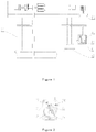
- FIG. 1 is an overall schematic diagram of a powerless opening device.
- FIG. 2 is a side schematic diagram of the powerless opening device.
- FIG. 3 is a schematic diagram of a damping device in the powerless opening device. As shown in FIG. 1 to FIG.
- the powerless opening device includes a case 01, a crank 02, a ratchet shaft 03, a pulling cable pulley 04, a ratchet 05, a pawl 06, a pressure spring 07, a friction plate 08, a friction ring 09, and a button 010.
- the ratchet shaft 03 is rotatably connected to the case 01.
- the pulling cable pulley 04, the ratchet 05, and the friction plate 08 are fixed on the ratchet shaft 03.
- the crank 02 is fixedly connected to the ratchet shaft 03 and extends outside of the case 01.
- One end of the pawl 06 is coupled to the pressure spring 07, and the other end of the pawl 06 is connected to the button 010.
- the friction ring 09 is also fixedly connected to the button 010.
- One end of the pulling cable 012 that is connected to the sliding opening sash 011 is fixedly connected to the pulling cable pulley 04.
- the pawl 06 is pressed by the pressure spring 07 to abut against the ratchet 05, the ratchet 05 cooperates with the pawl 06 to prevent the ratchet shaft 03 from rotating, thus preventing the pulling cable 012 wound on the ratchet shaft 03 from being released.
- the sliding opening sash 011 is in a stationary status.
- the button 010 is pressed down to a certain degree, the ratchet system is unlocked.
- the pulling cable 012 pulls the ratchet shaft 03 to rotate, and is unwound from the ratchet shaft 03; consequently, the sliding opening sash 011 moves downwardly.
- the friction ring 09 is in contact with the friction plate 08 and so as to generate a sliding frictional resistance, thereby preventing the sliding opening sash 011 from moving downwardly too quickly.
- the present invention provides a novel opening device for a sliding window.
- the present invention further provides a sliding window that uses the foregoing opening device.
- the present invention provides an opening device for a sliding window, comprising a base, a rotation shaft, a pulling cable, and a locking mechanism; wherein the rotation shaft is rotatably mounted on the base; the pulling cable is wound on the rotation shaft; and the locking mechanism is configured to control a rotation of the rotation shaft with respect to the base, characterized in that the opening device further comprises:
- the screw nut is provided with a threaded hole, and further comprises an adjustment screw that is threadably engaged with the threaded hole and abuts against the elastic member.
- an adjustment plate located between the elastic member and the adjustment screw is further included.
- the elastic member is a disk spring having a through hole; and the disk spring is sleeved on the lead screw via the through hole.
- the lead screw is coaxially disposed with the rotation shaft and is fixedly connected to the rotation shaft.
- the guiding member is a guide limiting hole provided in the base.
- a reel on which the pulling cable is wound is further included, wherein the reel is fixedly sleeved on the rotation shaft; and the reel has a helical groove for accommodating the pulling cable.
- an end portion of the rotation shaft and/or the lead screw has a groove for engaging a handle.
- the locking mechanism includes: a ratchet fixedly mounted on the rotation shaft or the lead screw, a pawl cooperating with the ratchet, and a sleeve fixedly mounted on the base; and the locking mechanism further includes a pressure spring, a spring positioning nut, a lever retaining pad, and a handle, wherein the spring positioning nut is fixed at an end portion of the sleeve that is away from the ratchet, and has a through hole for passing-through of the pawl; the pawl passes through the sleeve and the spring positioning nut, with one end of the pawl cooperating with the ratchet and the other end being provided with the lever retaining pad; the pressure spring is mounted in the sleeve, with one end of the pressure spring abutting against the pawl and the other end abutting against the spring positioning nut, so that the pawl engages/locks with the ratchet; the handle is hingedly mounted on the base, and one end end
- the present invention provides a sliding window, comprising a sliding opening sash and an opening device described previously, with a pulling cable of the opening device being connected to the sliding opening sash.
- the opening device provided in the present invention includes a pulling cable, a base, a rotation shaft, a first friction member, a second friction member, a lead screw, a screw nut, and an elastic member.
- the rotation shaft drives the lead screw to rotate, and the lead screw rotates to drive the screw nut to move towards the second friction member. Because one end of the elastic member abuts against the screw nut, and the other end abuts against the first friction member, during the moving process of the screw nut, the elastic member is compressed and deformed so as to make the first friction member abut against the second friction member.
- the elastic member As the rotation shaft continues to rotate, the elastic member is increasingly compressively deformed, and a deformational force acted on the first friction member is also gradually increased. Therefore, a friction force generated between the first friction member and the second friction member gradually increases.
- the friction force is gradually increased to be greater than a traction force of the pulling cable, so that a speed of the sliding opening sash is decreased to a certain degree when the sliding opening sash moves down to a lowest point, thereby preventing a lower frame and a side frame of a window from being seriously impacted due to an excessively great falling speed of the sliding opening sash, thereby reducing a possibility that the window may be deformed or damaged.
- the screw nut is provided with a threaded hole, and an adjustment screw is mounted in the threaded hole, with one end of the adjustment screw abutting against the elastic member and capable of rotating with respect to the threaded hole. Therefore, an initial deformation degree of the elastic member can be adjusted according to a magnitude of the pulling force on the pulling cable by the sliding opening sash, so as to be adapted with sliding opening sashes of different dimensions or weights.
- the sliding window provided in the present invention uses the foregoing opening device, may achieve beneficial effects as mentioned above, and the details thereof are not provided herein again.
- FIG. 1 to FIG. 3 01-case, 02-crank, 03-ratchet shaft, 04-pulling cable pulley, 05-ratchet, 06-pawl, 07-pressure spring, 08-friction plate, 09-friction ring, 010-button, 011-sliding opening sash, 012-pulling cable;
- FIG. 4 to FIG. 6 1-sliding opening sash, 2-pulling cable, 3-base, 31-guide limiting hole, 4-rotation shaft, 5-first friction member, 6-second friction member, 7-lead screw, 71-groove, 8-screw nut, 81-threaded hole, 9-disk spring, 10-adjustment screw, 11-adjustment plate, 12-reel, 13-ratchet, 14-pawl, 15-spring, 16-sleeve, 17-spring positioning nut, 18-lever retaining pad, 19-handle, 20-opening device, 21-movable pulley, 22-driving motor, 23-side frame.
- FIG. 4 is a cross-sectional view of an opening device for a sliding window according to an embodiment of the present invention
- FIG. 5 is a side view of an opening device according to an embodiment of the present invention.
- FIG. 5 is a side view of an opening device for a sliding window according to an embodiment of the present invention. It can be seen from FIG. 4 that the opening device in this embodiment includes a pulling cable 2, a base 3, a rotation shaft 4, a first friction member 5, a second friction member 6, a lead screw 7, a screw nut 8, a disk spring 9, and a locking mechanism.
- the base 3 is provided with a mounting chamber.
- the rotation shaft 4 is mounted in the mounting chamber of the base 3 by using a bearing and may rotate with respect to the base 3.
- One end of the pulling cable 2 is fixedly connected to the rotation shaft 4, and the other end is connected to the sliding opening sash 1 or a driving device that drives the sliding opening sash 1 to move.
- the locking mechanism is mounted between the base 3 and the rotation shaft 4 to control a rotation of the rotation shaft.
- the lead screw 7 is coaxially disposed with the rotation shaft 4 and is fixedly connected to the rotation shaft 4. The rotation shaft 4 drives the lead screw 7 to rotate together.
- a right side of the base 3 has a guide limiting hole 31.
- An extension direction of the guide limiting hole 31 is parallel to the axial direction of the lead screw 7 and the rotation shaft 4.
- the screw nut 8 is mounted in the guide limiting hole 31, and may move along the extension direction of the guide limiting hole 31.
- the guide limiting hole 31 limits the screw nut 8 to rotate along a circumferential direction.
- the lead screw 7 is threadably connected to the screw nut 8. Using the foregoing structure, when the lead screw 7 rotates, the screw nut 8 translates along an axial direction of the lead screw 7 by a guiding action of the guide limiting hole 31.
- a deformation direction of the disk spring 9 is parallel to an extension direction of the lead screw 7.
- One end of the disk spring 9 abuts against the screw nut 8, and the other end abuts against the first friction member 5.
- the second friction member 6 is fixedly mounted on the base 3.
- a friction surface of the first friction member faces a friction surface of the second friction member 6.
- the first friction member 5 is splined to the lead screw 7, and may move along the axial direction of the lead screw 7.
- a corresponding activation member is further provided on the opening device.
- the activation member When the activation member is activated, under a gravity force of the sliding opening sash 1, the pulling cable 2 is unwound from the rotation shaft 4 and drives the rotation shaft 4 to rotate.
- the screw nut 8 moves towards the second friction member 6 under a driving action of the lead screw 7 and a guiding action of the guide limiting hole 31. Because the second friction member 6 is fixedly mounted on the base 3, when the screw nut 8 arrives at a certain position, the disk spring 9 will deform and enable the friction surface of the first friction member 5 to be in contact with and engage with the friction surface of the second friction member 6. Due to a spline connection, the first friction member 5 rotates as the lead screw 7 rotates.
- Relative slip occurs between the friction surface of the first friction member 5 and the friction surface of the second friction member 6, thus generating a friction force.
- the friction force is smaller than a traction force that is acted on the pulling cable 2 by the sliding opening sash 1, the sliding opening sash 1 continues to move downwardly and drives the pulling cable 2 to be unwound.
- the friction force generated between the first friction member 5 and the second friction member 6 will be the same as the traction force that is acted on the pulling cable 2 by the sliding opening sash 1, and a declining speed of the sliding opening sash 1 reaches its maximum. At this time, the pulling cable 2 continues to be unwound.
- the speed of the sliding opening sash 1 has already been lowered when the sliding opening sash 1 moves to the lowest point. Therefore, impacts on a lower frame of a window and corresponding members may be reduced.
- the speed of the sliding opening sash 1 may also be reduced to be nearly zero when the sliding opening sash 1 moves to the lowest point, and an impacting force may also be reduced to minimum.
- the disk spring 9 of the opening device in this embodiment serve as an elastic member to generate deformation and increase the friction force.
- a plurality of disk springs 9 stacking together are used in this embodiment to increase an elastic force, so as to reduce a radial dimension of the lead screw 7 as much as possible, thereby further reduce a dimension of the entire opening device.
- Each disk spring 9 is provided with a central through hole, and is sleeved on the lead screw 7 via the through hole. It may be conceivable that to ensure a deformation, each disk spring 9 should be able to move along the axial direction of the lead screw 7. Certainly, in other embodiments, other types of elastic member may alternatively be used to replace with the disk spring 9.
- the rotation shaft 4 and the lead screw 7 in the opening device of this embodiment are coaxially and fixedly disposed.
- the rotation shaft 4 and the lead screw 7 may be integrally formed.
- the rotation shaft 4 and the lead screw 7 may not be coaxially disposed.
- the rotation shaft 4 and the lead screw 7 may be disposed to be parallel but not coaxial, with gears being provided at corresponding portions of the rotation shaft 4 and the lead screw 7; these two gears are meshed with each other, and the rotation shaft 4 drives the lead screw 7 to rotate via the meshing of the gears.
- the screw nut 8 in this embodiment further has a threaded hole 81.
- the screw nut 8 is further provided with an adjustment screw 10.
- the adjustment screw 10 is threadably engaged with the threaded hole 81, and one end of the adjustment screw 10 abuts against the disk spring 9.
- Weight variation of the sliding opening sash 1 causes the traction force acted on the pulling cable to be different.
- the foregoing threaded hole 81 and adjustment screw 10 are provided such that the deformation degree of the disk spring 9 may be adjusted according to an actual weight of the sliding opening sash 1 and a specific condition of the disk spring 9, thereby adaptively adjusting a magnitude of the friction force.
- adjustment screws 10 are provided both at an upper side and a lower side of the screw nut 8, ensuring an even deformation of the disk spring 9.
- an adjustment plate 11 is further provided in this embodiment.
- the adjustment plate 11 is a ring-shaped plate having a through hole.
- the adjustment plate 11 is sleeved on the lead screw 7 and is located between the disk spring 9 and the adjustment screw 10.
- the adjustment screw 10 adjusts the deformation degree of the disk spring 9 by adjusting a position of the adjustment plate 11.
- the adjustment screw 10 used in this embodiment is a countersunk screw.
- the countersunk screw is mounted in the threaded hole 81 and is not exposed. Therefore, sharp protruding portions of the entire opening device may be avoided/reduced. That is, a possibility of damage due to sharp protruding portions may be reduced.
- a reel 12 sleeved on the rotation shaft 4 is further included.
- a wiring slot for positioning the pulling cable 2 is provided on the reel 12.
- the locking mechanism includes a ratchet 13, a pawl 14, a sleeve 16, a pressure spring 15, a spring positioning nut 17, and a handle 19.
- the ratchet 13 is fixedly sleeved on the rotation shaft 4 or the lead screw 7, and may rotate as the rotation shaft 4 rotates.
- the pawl 14 and the pressure spring 15 are mounted in the sleeve 16.
- One end of the pawl 14 is engaged with ratchet teeth of the ratchet 13.
- the spring positioning nut 17 is mounted at a top end of the sleeve 16. The spring positioning nut 17 and the pawl 14 are clamped with the pressure spring 15 to compress the pressure spring 15.
- a deformational force generated by the compression of the pressure spring 15 is acted on the pawl 14, so that the pawl 14 is engaged with ratchet teeth.
- the other end of the pawl 14 extends outside the sleeve 16 and is provided with a lever retaining pad 18.
- the handle 19 is hingedly connected onto the base 3, with one end of the handle 19 abutting against a lower end of the lever retaining pad, and the other end being an operating end. When being turned to a right side, the handle 19 drives the lever retaining pad 18 and the pawl 14 to move upward and releases the engagement between the pawl 14 and the ratchet 13, thereby activating the opening device.
- the pawl 14 moves downwards under a deformational force of the pressure spring 15 and meshes/engages with the ratchet 13 again. It may be conceived that in other embodiments, other types of activation members such as a bolt may be disposed.
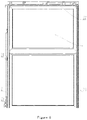
- FIG. 6 is a front view of a sliding window according to an embodiment of the present invention.
- the sliding window in this embodiment has the sliding opening sash 1, a side frame 23, a horizontal frame, and the foregoing opening device 20.
- the sliding opening sash 1 moves up and down along the side frame 23.
- a driving motor 22 and a pulley block are further provided in this embodiment.
- the foregoing opening device 20 is connected to a movable pulley 21 in the pulley block, so as to control the sliding opening sash 1 of the sliding window to be opened in cases of, such as, a power failure.
- the opening device 20 in this embodiment may also be directly used to drive the window to open or close, without providing the driving motor 22.
- a power member driving the pulling cable 2 to get wound should be further disposed on the opening device 20.
- a groove 71 for mounting a crank 02 may be further provided at an end portion of the lead screw 7. With the groove 71 and the crank 02, the lead screw 7 and the rotation shaft 4 may be driven to rotate, so that the pulling cable 2 may be wound onto the rotation shaft 4. In other embodiments, the winding of the pulling cable 2 may be achieved by using other power members.
Landscapes
- Engineering & Computer Science (AREA)
- Civil Engineering (AREA)
- Structural Engineering (AREA)
- Power-Operated Mechanisms For Wings (AREA)
- Devices For Conveying Motion By Means Of Endless Flexible Members (AREA)
- Wing Frames And Configurations (AREA)
- Transmission Devices (AREA)
Abstract
Description
- This application claims the priority of the Chinese patent application No.
201610642725.X - The present invention relates to the technical field of sliding windows, and in particular to an opening device for a sliding window. In addition, the present invention further relates to a sliding window that uses the foregoing opening device.
- A sliding window is a novel window in which a window sash can be opened in a vertical direction, and is gradually adopted in the field of building construction. A sliding window mainly includes a sliding opening sash, a window frame, and an opening device. The window frame further includes vertical frames and horizontal frames. A redirection guiding member is mounted on the vertical frame. A guiding member is mounted on a surface at which the sliding opening sash fits with the vertical frame. The guiding member is inserted into the redirection guiding member and can move up and down along the redirection guiding member. A pulling cable in the opening device is connected to the sliding opening sash, and the pulling cable pulls the sliding opening sash to move up and down along the redirection guiding member. Generally, a driving motor is provided as the power member of the sliding window. The driving motor rotates and drives a corresponding transmission mechanism and the pulling cable, thereby achieving opening and closing of the sliding window. However, when a power failure or other situations occurs in a building, the driving motor cannot rotate, and therefore the sliding opening sash cannot be normally opened or closed.
- In order to realize a normal open or close of a sliding window in a case of power failure, the utility model patent No.
201420424671.6 FIG. 1 is an overall schematic diagram of a powerless opening device.FIG. 2 is a side schematic diagram of the powerless opening device.FIG. 3 is a schematic diagram of a damping device in the powerless opening device. As shown inFIG. 1 to FIG. 3 , the powerless opening device includes acase 01, acrank 02, aratchet shaft 03, apulling cable pulley 04, aratchet 05, apawl 06, apressure spring 07, afriction plate 08, afriction ring 09, and abutton 010. Theratchet shaft 03 is rotatably connected to thecase 01. Thepulling cable pulley 04, theratchet 05, and thefriction plate 08 are fixed on theratchet shaft 03. Thecrank 02 is fixedly connected to theratchet shaft 03 and extends outside of thecase 01. One end of thepawl 06 is coupled to thepressure spring 07, and the other end of thepawl 06 is connected to thebutton 010. Thefriction ring 09 is also fixedly connected to thebutton 010. One end of thepulling cable 012 that is connected to the slidingopening sash 011 is fixedly connected to thepulling cable pulley 04. When thepawl 06 is pressed by thepressure spring 07 to abut against theratchet 05, theratchet 05 cooperates with thepawl 06 to prevent theratchet shaft 03 from rotating, thus preventing the pullingcable 012 wound on theratchet shaft 03 from being released. The slidingopening sash 011 is in a stationary status. When thebutton 010 is pressed down to a certain degree, the ratchet system is unlocked. Due to a gravity force of the slidingopening sash 011, thepulling cable 012 pulls theratchet shaft 03 to rotate, and is unwound from theratchet shaft 03; consequently, the slidingopening sash 011 moves downwardly. As thebutton 010 is pressed down, thefriction ring 09 is in contact with thefriction plate 08 and so as to generate a sliding frictional resistance, thereby preventing the slidingopening sash 011 from moving downwardly too quickly. - However, when the foregoing powerless opening device is used, a magnitude of the friction force produced by the
friction ring 09 and thefriction plate 08 is determined by a pressing pressure of thebutton 010. However, in actual operations, it is very difficult for an operator to control pressure of thebutton 010. Therefore, the friction force generated between thefriction ring 09 and thefriction plate 08 also changes as the pressure of thebutton 010 changes. As a result, it is also relatively difficult to control a declining speed of the slidingopening sash 011. If the friction force is smaller than a traction force that is applied by the sliding opening sash on thepulling cable 012, the declining speed of the slidingopening sash 011 during the declining process will become faster and faster, and a lower frame and a side frame of a window may be seriously impacted when the slidingopening sash 011 reaches the lower frame of the window, resulting in a local deformation or damage to the window. Therefore, it is a problem to be resolved by a person skilled in the art to provide an opening device that can still work in a power off state and that can effectively control a falling speed of a sliding opening sash. - To resolve a problem that a prior art powerless opening device cannot provide sufficient friction force to reduce an impacting force of a sliding opening sash on a window frame when the sliding opening sash moves downwardly, the present invention provides a novel opening device for a sliding window. In addition, the present invention further provides a sliding window that uses the foregoing opening device.
- The present invention provides an opening device for a sliding window, comprising a base, a rotation shaft, a pulling cable, and a locking mechanism; wherein the rotation shaft is rotatably mounted on the base; the pulling cable is wound on the rotation shaft; and the locking mechanism is configured to control a rotation of the rotation shaft with respect to the base, characterized in that the opening device further comprises:
- a lead screw connected to the rotation shaft and rotating with the rotation shaft;
- a screw nut threadably engaged with the lead screw;
- a guiding member guiding the screw nut to move along an axial direction of the lead screw, thus confining a rotation of the screw nut, where in the guiding member is fixedly provided on the base;
- a first friction member sleeved on the lead screw, rotating with the lead screw, and being movable along the axial direction of the lead screw;
- a second friction member fixedly mounted on the base and in frictional engagement with the first friction member, wherein the second friction member and the screw nut are respectively provided at two sides of the first friction member; and
- an elastic member provided between the first friction member and the screw nut, wherein
- when the rotation shaft rotates in a first direction, the pulling cable is unwound from the rotation shaft, and the screw nut rotates towards the second friction member and presses the elastic member.
- Optionally, the screw nut is provided with a threaded hole, and further comprises an adjustment screw that is threadably engaged with the threaded hole and abuts against the elastic member.
- Optionally, an adjustment plate located between the elastic member and the adjustment screw is further included.
- Optionally, the elastic member is a disk spring having a through hole; and the disk spring is sleeved on the lead screw via the through hole.
- Optionally, the lead screw is coaxially disposed with the rotation shaft and is fixedly connected to the rotation shaft.
- Optionally, the guiding member is a guide limiting hole provided in the base.
- Optionally, a reel on which the pulling cable is wound is further included, wherein the reel is fixedly sleeved on the rotation shaft; and the reel has a helical groove for accommodating the pulling cable.
- Optionally, an end portion of the rotation shaft and/or the lead screw has a groove for engaging a handle.
- Optionally, the locking mechanism includes: a ratchet fixedly mounted on the rotation shaft or the lead screw, a pawl cooperating with the ratchet, and a sleeve fixedly mounted on the base; and the locking mechanism further includes a pressure spring, a spring positioning nut, a lever retaining pad, and a handle, wherein the spring positioning nut is fixed at an end portion of the sleeve that is away from the ratchet, and has a through hole for passing-through of the pawl; the pawl passes through the sleeve and the spring positioning nut, with one end of the pawl cooperating with the ratchet and the other end being provided with the lever retaining pad; the pressure spring is mounted in the sleeve, with one end of the pressure spring abutting against the pawl and the other end abutting against the spring positioning nut, so that the pawl engages/locks with the ratchet; the handle is hingedly mounted on the base, and one end of the handle abuts against a lower end of the lever retaining pad.
- The present invention provides a sliding window, comprising a sliding opening sash and an opening device described previously, with a pulling cable of the opening device being connected to the sliding opening sash.
- The opening device provided in the present invention includes a pulling cable, a base, a rotation shaft, a first friction member, a second friction member, a lead screw, a screw nut, and an elastic member. When the pulling cable is unwound from the rotation shaft, the rotation shaft drives the lead screw to rotate, and the lead screw rotates to drive the screw nut to move towards the second friction member. Because one end of the elastic member abuts against the screw nut, and the other end abuts against the first friction member, during the moving process of the screw nut, the elastic member is compressed and deformed so as to make the first friction member abut against the second friction member. As the rotation shaft continues to rotate, the elastic member is increasingly compressively deformed, and a deformational force acted on the first friction member is also gradually increased. Therefore, a friction force generated between the first friction member and the second friction member gradually increases. During a declining process of the sliding opening sash, the friction force is gradually increased to be greater than a traction force of the pulling cable, so that a speed of the sliding opening sash is decreased to a certain degree when the sliding opening sash moves down to a lowest point, thereby preventing a lower frame and a side frame of a window from being seriously impacted due to an excessively great falling speed of the sliding opening sash, thereby reducing a possibility that the window may be deformed or damaged.
- According to an embodiment of the present invention, the screw nut is provided with a threaded hole, and an adjustment screw is mounted in the threaded hole, with one end of the adjustment screw abutting against the elastic member and capable of rotating with respect to the threaded hole. Therefore, an initial deformation degree of the elastic member can be adjusted according to a magnitude of the pulling force on the pulling cable by the sliding opening sash, so as to be adapted with sliding opening sashes of different dimensions or weights.
- The sliding window provided in the present invention uses the foregoing opening device, may achieve beneficial effects as mentioned above, and the details thereof are not provided herein again.
- To more clearly describe the background or the technical solutions of the present invention, the prior art or specific embodiments will be briefly described below in combination with accompanying drawings. Obviously, the accompanying drawings in combination with specific embodiments are merely used for an easy understanding of the present invention. For persons ordinarily skill in the art, other drawings can be derived according to these accompanying drawings without a creative effect.
-
FIG. 1 is an overall schematic diagram of a powerless opening device; -
FIG. 2 is a side schematic diagram of a powerless opening device; -
FIG. 3 is a schematic diagram of a damping device in a powerless opening device; -
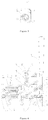
FIG. 4 is a cross-sectional view of an opening device for a sliding window according to an embodiment of the present invention; -
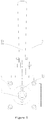
FIG. 5 is a side view of an opening device for a sliding window according to an embodiment of the present invention; and -
FIG. 6 is a front view of a sliding window according to an embodiment of the present invention. - In
FIG. 1 to FIG. 3 : 01-case, 02-crank, 03-ratchet shaft, 04-pulling cable pulley, 05-ratchet, 06-pawl, 07-pressure spring, 08-friction plate, 09-friction ring, 010-button, 011-sliding opening sash, 012-pulling cable; - In
FIG. 4 to FIG. 6 : 1-sliding opening sash, 2-pulling cable, 3-base, 31-guide limiting hole, 4-rotation shaft, 5-first friction member, 6-second friction member, 7-lead screw, 71-groove, 8-screw nut, 81-threaded hole, 9-disk spring, 10-adjustment screw, 11-adjustment plate, 12-reel, 13-ratchet, 14-pawl, 15-spring, 16-sleeve, 17-spring positioning nut, 18-lever retaining pad, 19-handle, 20-opening device, 21-movable pulley, 22-driving motor, 23-side frame. - The technical solutions in the embodiments of the present invention are described in detail with reference to the accompanying drawings in the embodiments of the present invention.
-
FIG. 4 is a cross-sectional view of an opening device for a sliding window according to an embodiment of the present invention;FIG. 5 is a side view of an opening device according to an embodiment of the present invention.FIG. 5 is a side view of an opening device for a sliding window according to an embodiment of the present invention. It can be seen fromFIG. 4 that the opening device in this embodiment includes a pullingcable 2, a base 3, a rotation shaft 4, a first friction member 5, asecond friction member 6, alead screw 7, ascrew nut 8, adisk spring 9, and a locking mechanism. - The base 3 is provided with a mounting chamber. The rotation shaft 4 is mounted in the mounting chamber of the base 3 by using a bearing and may rotate with respect to the base 3. One end of the pulling
cable 2 is fixedly connected to the rotation shaft 4, and the other end is connected to the sliding opening sash 1 or a driving device that drives the sliding opening sash 1 to move. The locking mechanism is mounted between the base 3 and the rotation shaft 4 to control a rotation of the rotation shaft. Thelead screw 7 is coaxially disposed with the rotation shaft 4 and is fixedly connected to the rotation shaft 4. The rotation shaft 4 drives thelead screw 7 to rotate together. - A right side of the base 3 has a
guide limiting hole 31. An extension direction of theguide limiting hole 31 is parallel to the axial direction of thelead screw 7 and the rotation shaft 4. Thescrew nut 8 is mounted in theguide limiting hole 31, and may move along the extension direction of theguide limiting hole 31. Theguide limiting hole 31 limits thescrew nut 8 to rotate along a circumferential direction. Thelead screw 7 is threadably connected to thescrew nut 8. Using the foregoing structure, when thelead screw 7 rotates, thescrew nut 8 translates along an axial direction of thelead screw 7 by a guiding action of theguide limiting hole 31. - A deformation direction of the
disk spring 9 is parallel to an extension direction of thelead screw 7. One end of thedisk spring 9 abuts against thescrew nut 8, and the other end abuts against the first friction member 5. Thesecond friction member 6 is fixedly mounted on the base 3. A friction surface of the first friction member faces a friction surface of thesecond friction member 6. The first friction member 5 is splined to thelead screw 7, and may move along the axial direction of thelead screw 7. - In addition, a corresponding activation member is further provided on the opening device. When the activation member is activated, under a gravity force of the sliding opening sash 1, the pulling
cable 2 is unwound from the rotation shaft 4 and drives the rotation shaft 4 to rotate. Thescrew nut 8 moves towards thesecond friction member 6 under a driving action of thelead screw 7 and a guiding action of theguide limiting hole 31. Because thesecond friction member 6 is fixedly mounted on the base 3, when thescrew nut 8 arrives at a certain position, thedisk spring 9 will deform and enable the friction surface of the first friction member 5 to be in contact with and engage with the friction surface of thesecond friction member 6. Due to a spline connection, the first friction member 5 rotates as thelead screw 7 rotates. Relative slip occurs between the friction surface of the first friction member 5 and the friction surface of thesecond friction member 6, thus generating a friction force. However, because the friction force is smaller than a traction force that is acted on the pullingcable 2 by the sliding opening sash 1, the sliding opening sash 1 continues to move downwardly and drives the pullingcable 2 to be unwound. - As the rotation shaft 4 continues to rotate, a distance between the
screw nut 8 and thesecond friction member 6 is gradually reduced. A deformation degree of thedisk spring 9 becomes greater under the squeezing action of thescrew nut 8 and thesecond friction member 6, and therefore, the resulted elastic deformational force becomes greater. The deformational force generated by thedisk spring 9 is acted on the first friction member 5, so that the friction force between the friction surface of the first friction member 5 and the friction surface of thesecond friction member 6 is gradually increased. When the pullingcable 2 is unwound to a certain degree, the friction force generated between the first friction member 5 and thesecond friction member 6 will be the same as the traction force that is acted on the pullingcable 2 by the sliding opening sash 1, and a declining speed of the sliding opening sash 1 reaches its maximum. At this time, the pullingcable 2 continues to be unwound. - As the pulling
cable 2 continues to be unwound, thescrew nut 8 continues to approach thesecond friction member 6, the deformation degree of thedisk spring 9 is further increased, the friction force between the first friction member 5 and thesecond friction member 6 becomes greater than the traction force that is acted on the pullingcable 2 by the sliding opening sash 1, the declining speed of the sliding opening sash 1 is lowered, and a unwinding speed of the pullingcable 2 is also lowered. Finally, when the sliding opening sash 1 moves to a lowest point, unwinding of the pullingcable 2 is basically completed. - Using the foregoing opening device, the speed of the sliding opening sash 1 has already been lowered when the sliding opening sash 1 moves to the lowest point. Therefore, impacts on a lower frame of a window and corresponding members may be reduced. In specific implementations, if the distance between the
screw nut 8 and thesecond friction member 6, a friction coefficient between the friction surface of the first friction member 5 and the friction surface of thesecond friction member 6, and an elastic deformation coefficient of thedisk spring 9 are reasonably selected, the speed of the sliding opening sash 1 may also be reduced to be nearly zero when the sliding opening sash 1 moves to the lowest point, and an impacting force may also be reduced to minimum. - The
disk spring 9 of the opening device in this embodiment serve as an elastic member to generate deformation and increase the friction force. As shown inFIG. 4 , a plurality of disk springs 9 stacking together are used in this embodiment to increase an elastic force, so as to reduce a radial dimension of thelead screw 7 as much as possible, thereby further reduce a dimension of the entire opening device. Eachdisk spring 9 is provided with a central through hole, and is sleeved on thelead screw 7 via the through hole. It may be conceivable that to ensure a deformation, eachdisk spring 9 should be able to move along the axial direction of thelead screw 7. Certainly, in other embodiments, other types of elastic member may alternatively be used to replace with thedisk spring 9. - As stated above, the rotation shaft 4 and the
lead screw 7 in the opening device of this embodiment are coaxially and fixedly disposed. In practical productions, the rotation shaft 4 and thelead screw 7 may be integrally formed. Certainly, in other implementations, the rotation shaft 4 and thelead screw 7 may not be coaxially disposed. For example, the rotation shaft 4 and thelead screw 7 may be disposed to be parallel but not coaxial, with gears being provided at corresponding portions of the rotation shaft 4 and thelead screw 7; these two gears are meshed with each other, and the rotation shaft 4 drives thelead screw 7 to rotate via the meshing of the gears. - As shown in
FIG. 5 , thescrew nut 8 in this embodiment further has a threadedhole 81. In addition, thescrew nut 8 is further provided with anadjustment screw 10. Theadjustment screw 10 is threadably engaged with the threadedhole 81, and one end of theadjustment screw 10 abuts against thedisk spring 9. In practical production applications, as the dimension of the sliding opening sash 1 varies, the corresponding weight will also vary. Weight variation of the sliding opening sash 1 causes the traction force acted on the pulling cable to be different. The foregoing threadedhole 81 andadjustment screw 10 are provided such that the deformation degree of thedisk spring 9 may be adjusted according to an actual weight of the sliding opening sash 1 and a specific condition of thedisk spring 9, thereby adaptively adjusting a magnitude of the friction force. As shown inFIG. 4 andFIG. 5 , adjustment screws 10 are provided both at an upper side and a lower side of thescrew nut 8, ensuring an even deformation of thedisk spring 9. To further ensure an even deformation in a circumferential direction of thedisk spring 9, anadjustment plate 11 is further provided in this embodiment. Theadjustment plate 11 is a ring-shaped plate having a through hole. Theadjustment plate 11 is sleeved on thelead screw 7 and is located between thedisk spring 9 and theadjustment screw 10. Theadjustment screw 10 adjusts the deformation degree of thedisk spring 9 by adjusting a position of theadjustment plate 11. As shown inFIG. 4 andFIG. 5 , theadjustment screw 10 used in this embodiment is a countersunk screw. The countersunk screw is mounted in the threadedhole 81 and is not exposed. Therefore, sharp protruding portions of the entire opening device may be avoided/reduced. That is, a possibility of damage due to sharp protruding portions may be reduced. - In this embodiment, what confines the rotation of the
screw nut 8 is theguide limiting hole 31 provided in the base 3. In other embodiments, other structural guiding members may be alternatively used to replace theguide limiting hole 31. - In addition, as shown in
FIG. 4 , to make sure that the pullingcable 2 may be properly wound on the rotation shaft 4, areel 12 sleeved on the rotation shaft 4 is further included. A wiring slot for positioning the pullingcable 2 is provided on thereel 12. - As shown in
FIG. 4 , the locking mechanism includes a ratchet 13, apawl 14, asleeve 16, apressure spring 15, a spring positioning nut 17, and ahandle 19. The ratchet 13 is fixedly sleeved on the rotation shaft 4 or thelead screw 7, and may rotate as the rotation shaft 4 rotates. Thepawl 14 and thepressure spring 15 are mounted in thesleeve 16. One end of thepawl 14 is engaged with ratchet teeth of the ratchet 13. The spring positioning nut 17 is mounted at a top end of thesleeve 16. The spring positioning nut 17 and thepawl 14 are clamped with thepressure spring 15 to compress thepressure spring 15. A deformational force generated by the compression of thepressure spring 15 is acted on thepawl 14, so that thepawl 14 is engaged with ratchet teeth. In addition, the other end of thepawl 14 extends outside thesleeve 16 and is provided with alever retaining pad 18. Thehandle 19 is hingedly connected onto the base 3, with one end of thehandle 19 abutting against a lower end of the lever retaining pad, and the other end being an operating end. When being turned to a right side, thehandle 19 drives thelever retaining pad 18 and thepawl 14 to move upward and releases the engagement between thepawl 14 and the ratchet 13, thereby activating the opening device. When thehandle 19 is released, thepawl 14 moves downwards under a deformational force of thepressure spring 15 and meshes/engages with the ratchet 13 again. It may be conceived that in other embodiments, other types of activation members such as a bolt may be disposed. -
FIG. 6 is a front view of a sliding window according to an embodiment of the present invention. As shown inFIG. 5 , the sliding window in this embodiment has the sliding opening sash 1, aside frame 23, a horizontal frame, and the foregoingopening device 20. The sliding opening sash 1 moves up and down along theside frame 23. Specifically, a drivingmotor 22 and a pulley block are further provided in this embodiment. The foregoingopening device 20 is connected to amovable pulley 21 in the pulley block, so as to control the sliding opening sash 1 of the sliding window to be opened in cases of, such as, a power failure. In addition, in some cases in which electric wires are inconvenient to be arranged, theopening device 20 in this embodiment may also be directly used to drive the window to open or close, without providing the drivingmotor 22. To open or close the window, a power member driving the pullingcable 2 to get wound should be further disposed on theopening device 20. As shown inFIG. 4 , agroove 71 for mounting a crank 02 may be further provided at an end portion of thelead screw 7. With thegroove 71 and thecrank 02, thelead screw 7 and the rotation shaft 4 may be driven to rotate, so that the pullingcable 2 may be wound onto the rotation shaft 4. In other embodiments, the winding of the pullingcable 2 may be achieved by using other power members. - The opening device and the sliding window in the embodiments of the present invention are described above in detail. Principles and implementations of the present invention are described herein with specific embodiments. The foregoing descriptions of the embodiments are merely intended to help to understand the core concept of the present invention. All other embodiments derived by persons of ordinary skill in the art without departing from the principles of the present invention and without an inventive effort shall fall within the protection scope of the present invention.
Claims (10)
- An opening device for a sliding window, comprising a base (3), a rotation shaft (4), a pulling cable (2), and a locking mechanism, wherein
the rotation shaft (4) is rotatably mounted on the base (3); the pulling cable (2) is wound on the rotation shaft (4); and the locking mechanism is configured to control a rotation of the rotation shaft (4) with respect to the base (3), characterized in that the opening device further comprises:a lead screw (7) connected to the rotation shaft (4) and rotating with the rotation shaft (4);a screw nut (8) threadably engaged with the lead screw (7);a guiding member guiding the screw nut (8) to move along an axial direction of the lead screw (7), thus confining a rotation of the screw nut (8), wherein the guiding member is fixedly disposed on the base (3);a first friction member (5) sleeved on the lead screw (7), rotating with the lead screw (7), and being movable along the axial direction of the lead screw (7);a second friction member (6) fixedly mounted on the base (3) and in frictional engagement with the first friction member (5), wherein the second friction member (6) and the screw nut (8) are respectively provided at two opposite sides of the first friction member (5); andan elastic member provided between the first friction member (5) and the screw nut (8), whereinwhen the rotation shaft (4) rotates in a first direction, the pulling cable (2) is unwound from the rotation shaft (4), and the screw nut (8) rotates towards the second friction member (6) and presses the elastic member. - The opening device for a sliding window according to claim 1, characterized in that:
the screw nut (8) is provided with a threaded hole (81), and further comprises an adjustment screw (10) that is threadably engaged with the threaded hole (81) and abuts against the elastic member. - The opening device for a sliding window according to claim 2, characterized in that:
the opening device further comprises an adjustment plate (11) provided between the elastic member and the adjustment screw (10). - The opening device for a sliding window according to claims 1 to 3, characterized in that:
the elastic member is a disk spring (9) having a through hole, wherein the disk spring (9) is sleeved on the lead screw (7) via the through hole. - The opening device for a sliding window according to claim 4, characterized in that:
the lead screw (7) is coaxially disposed with the rotation shaft (4) and is fixedly connected to the rotation shaft (4). - The opening device for a sliding window according to claim 5, characterized in that:
the guiding member is a guide limiting hole (31) provided in the base (3). - The opening device for a sliding window according to claim 6, characterized in that:
the opening device further comprises a reel (12) on which the pulling cable (2) is wound, wherein the reel (12) is fixedly sleeved on the rotation shaft (4); and the reel (12) has a helical groove for accommodating the pulling cable (2). - The opening device for a sliding window according to claim 7, characterized in that:
an end portion of the rotation shaft (4) and/or the lead screw (7) has a groove (71) for engaging a crank. - The opening device for a sliding window according to any one of claims 1 to 3, characterized in that the locking mechanism comprises:a ratchet (13) fixedly mounted on the rotation shaft (4) or the lead screw (7), a pawl (14) cooperating with the ratchet (13), and a sleeve (16) fixedly mounted on the base (13); whereinthe locking mechanism further comprises a pressure spring (15), a spring positioning nut (17), a lever retaining pad (18), and a handle (19), whereinthe spring positioning nut (17) is fixedly mounted at an end portion of the sleeve (16) that is away from the ratchet (13), and has a through hole for passing-through of the pawl (14);the pawl (14) passes through the sleeve (16) and the spring positioning nut (17), with one end of the pawl (14) cooperating with the ratchet (13), and the other end being provided with the lever retaining pad (18);the pressure spring (15) is mounted in the sleeve (16), with one end of the pressure spring (15) abutting against the pawl (14), and the other end abutting against the spring positioning nut (17), so that the pawl (14) locks with the ratchet (13); andthe handle (19) is hingedly mounted on the base (3), and one end of the handle (19) abuts against a lower end of the lever retaining pad (18).
- A sliding window, characterized by comprising a sliding opening sash (1) and an opening device (20) according to any one of claims 1 to 9, whererin the pulling cable (2) of the opening device (20) is connected with the sliding opening sash (1).
Applications Claiming Priority (2)
| Application Number | Priority Date | Filing Date | Title |
|---|---|---|---|
| CN201610642725.XA CN107701006B (en) | 2016-08-08 | 2016-08-08 | A kind of opening device and a kind of sliding window for sliding window |
| PCT/CN2017/077032 WO2018028203A1 (en) | 2016-08-08 | 2017-03-17 | Opening device used in sliding window and sliding window |
Publications (3)
| Publication Number | Publication Date |
|---|---|
| EP3498957A1 true EP3498957A1 (en) | 2019-06-19 |
| EP3498957A4 EP3498957A4 (en) | 2020-06-03 |
| EP3498957B1 EP3498957B1 (en) | 2021-03-03 |
Family
ID=61162614
Family Applications (1)
| Application Number | Title | Priority Date | Filing Date |
|---|---|---|---|
| EP17838336.0A Not-in-force EP3498957B1 (en) | 2016-08-08 | 2017-03-17 | Opening device used in sliding window and sliding window |
Country Status (4)
| Country | Link |
|---|---|
| EP (1) | EP3498957B1 (en) |
| CN (1) | CN107701006B (en) |
| DK (1) | DK3498957T3 (en) |
| WO (1) | WO2018028203A1 (en) |
Families Citing this family (3)
| Publication number | Priority date | Publication date | Assignee | Title |
|---|---|---|---|---|
| CN108331479B (en) * | 2017-01-19 | 2019-09-10 | 长春阔尔科技股份有限公司 | A kind of sliding window emergency opening system |
| CN112220570A (en) * | 2020-10-26 | 2021-01-15 | 珠海市人民医院 | Rotary pin-type dental implant structure and using method |
| CN112461107A (en) * | 2020-11-11 | 2021-03-09 | 唐立政 | Tunnel deformation measuring device |
Family Cites Families (10)
| Publication number | Priority date | Publication date | Assignee | Title |
|---|---|---|---|---|
| GB430457A (en) * | 1933-07-03 | 1935-06-19 | Braun Karl | Improvements in or relating to windows |
| US4697304A (en) * | 1986-07-11 | 1987-10-06 | The Celotex Corporation | Friction controlled window balance |
| CN1995671A (en) * | 2005-12-31 | 2007-07-11 | 张俊成 | Automatic reset device by using gravity |
| KR20090068883A (en) * | 2007-12-24 | 2009-06-29 | 윤선화 | Door closer |
| CN103748305B (en) * | 2011-06-29 | 2016-05-18 | 亚萨合莱自动门系统有限公司 | Vertical sliding door assembly |
| CN202910765U (en) * | 2012-11-13 | 2013-05-01 | 南通昱品通信科技有限公司 | Wire coil clamp protective device |
| JP2014181554A (en) * | 2013-03-18 | 2014-09-29 | Yuichi Umeda | Hybrid semi-automatic door |
| CN204024296U (en) * | 2014-07-30 | 2014-12-17 | 长春阔尔科技股份有限公司 | Open system that vertical sliding motion side window is unpowered |
| CN104328999B (en) * | 2014-11-19 | 2016-06-29 | 盐城工学院 | A kind of multifunctional burglary-resistant escape window |
| CN205422431U (en) * | 2015-12-16 | 2016-08-03 | 江西朝阳机械厂 | Board -like fire window that shifts up of weighing apparatus power |
-
2016
- 2016-08-08 CN CN201610642725.XA patent/CN107701006B/en active Active
-
2017
- 2017-03-17 WO PCT/CN2017/077032 patent/WO2018028203A1/en not_active Ceased
- 2017-03-17 EP EP17838336.0A patent/EP3498957B1/en not_active Not-in-force
- 2017-03-17 DK DK17838336.0T patent/DK3498957T3/en active
Also Published As
| Publication number | Publication date |
|---|---|
| EP3498957B1 (en) | 2021-03-03 |
| DK3498957T3 (en) | 2021-05-31 |
| CN107701006A (en) | 2018-02-16 |
| WO2018028203A1 (en) | 2018-02-15 |
| CN107701006B (en) | 2019-02-05 |
| EP3498957A4 (en) | 2020-06-03 |
Similar Documents
| Publication | Publication Date | Title |
|---|---|---|
| US9816317B2 (en) | Spring-assisted cordless roller shade without clutch system | |
| EP3498957B1 (en) | Opening device used in sliding window and sliding window | |
| US20080099157A1 (en) | Device for winding suspension cord of blind | |
| US8579086B2 (en) | Crash safety device having a rope drive mechanism | |
| US11473341B2 (en) | Sliding window emergency opening system | |
| CN110924771B (en) | Automobile limiting mechanism | |
| CN108821054B (en) | Car anti-falling device and car lifting system | |
| JP5107698B2 (en) | Roll screen | |
| EP1903174A1 (en) | Device for winding a suspension cord of a blind | |
| CN214886347U (en) | Anti-falling safety device and lifting equipment of industrial door | |
| CN210033227U (en) | Electric door rolling machine | |
| CN216730461U (en) | Stable feeding mechanism of hinge pin | |
| CN115680464A (en) | A hole-free installation mechanism and curtain | |
| US4428252A (en) | Actuator device for opening a sliding door | |
| JP6140494B2 (en) | Opening / closing member stop device for opening / closing device | |
| JP4294527B2 (en) | Seat elevating control device in entrance / exit seat opening / closing machine | |
| JP6438918B2 (en) | Braking device and solar shading device using the same | |
| CN211818892U (en) | Anti-collision reverse force protection mechanism of automatic vertical hinged door machine | |
| CN220415219U (en) | Balancing weight locking mechanism of hollow shutter | |
| CN221546828U (en) | Manual control device for roller shutter door | |
| EP1783316A2 (en) | On-failure blind stopper system | |
| CN214576681U (en) | Rolling gate anti-falling device and rolling gate with same | |
| CN114000795B (en) | Manual-automatic integrated power-assisted electric lifting window | |
| CN116044300A (en) | A kind of operating mechanism and curtain | |
| JP7328867B2 (en) | Shielding device |
Legal Events
| Date | Code | Title | Description |
|---|---|---|---|
| STAA | Information on the status of an ep patent application or granted ep patent |
Free format text: STATUS: THE INTERNATIONAL PUBLICATION HAS BEEN MADE |
|
| PUAI | Public reference made under article 153(3) epc to a published international application that has entered the european phase |
Free format text: ORIGINAL CODE: 0009012 |
|
| STAA | Information on the status of an ep patent application or granted ep patent |
Free format text: STATUS: REQUEST FOR EXAMINATION WAS MADE |
|
| 17P | Request for examination filed |
Effective date: 20190307 |
|
| AK | Designated contracting states |
Kind code of ref document: A1 Designated state(s): AL AT BE BG CH CY CZ DE DK EE ES FI FR GB GR HR HU IE IS IT LI LT LU LV MC MK MT NL NO PL PT RO RS SE SI SK SM TR |
|
| AX | Request for extension of the european patent |
Extension state: BA ME |
|
| DAV | Request for validation of the european patent (deleted) | ||
| DAX | Request for extension of the european patent (deleted) | ||
| A4 | Supplementary search report drawn up and despatched |
Effective date: 20200507 |
|
| RIC1 | Information provided on ipc code assigned before grant |
Ipc: E05F 3/16 20060101ALI20200429BHEP Ipc: E05F 5/02 20060101ALI20200429BHEP Ipc: E05F 11/48 20060101AFI20200429BHEP Ipc: E06B 3/44 20060101ALI20200429BHEP Ipc: E05F 11/50 20060101ALI20200429BHEP Ipc: E05F 1/16 20060101ALI20200429BHEP |
|
| GRAP | Despatch of communication of intention to grant a patent |
Free format text: ORIGINAL CODE: EPIDOSNIGR1 |
|
| STAA | Information on the status of an ep patent application or granted ep patent |
Free format text: STATUS: GRANT OF PATENT IS INTENDED |
|
| RIC1 | Information provided on ipc code assigned before grant |
Ipc: E05F 3/16 20060101ALI20201020BHEP Ipc: E06B 3/44 20060101ALI20201020BHEP Ipc: E05F 5/02 20060101ALI20201020BHEP Ipc: E05F 11/50 20060101ALI20201020BHEP Ipc: E05F 1/16 20060101ALI20201020BHEP Ipc: E05F 11/48 20060101AFI20201020BHEP |
|
| INTG | Intention to grant announced |
Effective date: 20201113 |
|
| GRAS | Grant fee paid |
Free format text: ORIGINAL CODE: EPIDOSNIGR3 |
|
| GRAA | (expected) grant |
Free format text: ORIGINAL CODE: 0009210 |
|
| STAA | Information on the status of an ep patent application or granted ep patent |
Free format text: STATUS: THE PATENT HAS BEEN GRANTED |
|
| AK | Designated contracting states |
Kind code of ref document: B1 Designated state(s): AL AT BE BG CH CY CZ DE DK EE ES FI FR GB GR HR HU IE IS IT LI LT LU LV MC MK MT NL NO PL PT RO RS SE SI SK SM TR |
|
| REG | Reference to a national code |
Ref country code: GB Ref legal event code: FG4D |
|
| REG | Reference to a national code |
Ref country code: AT Ref legal event code: REF Ref document number: 1367372 Country of ref document: AT Kind code of ref document: T Effective date: 20210315 Ref country code: CH Ref legal event code: EP |
|
| REG | Reference to a national code |
Ref country code: DE Ref legal event code: R096 Ref document number: 602017034040 Country of ref document: DE |
|
| REG | Reference to a national code |
Ref country code: IE Ref legal event code: FG4D |
|
| REG | Reference to a national code |
Ref country code: DK Ref legal event code: T3 Effective date: 20210528 |
|
| REG | Reference to a national code |
Ref country code: LT Ref legal event code: MG9D |
|
| PG25 | Lapsed in a contracting state [announced via postgrant information from national office to epo] |
Ref country code: GR Free format text: LAPSE BECAUSE OF FAILURE TO SUBMIT A TRANSLATION OF THE DESCRIPTION OR TO PAY THE FEE WITHIN THE PRESCRIBED TIME-LIMIT Effective date: 20210604 Ref country code: HR Free format text: LAPSE BECAUSE OF FAILURE TO SUBMIT A TRANSLATION OF THE DESCRIPTION OR TO PAY THE FEE WITHIN THE PRESCRIBED TIME-LIMIT Effective date: 20210303 Ref country code: FI Free format text: LAPSE BECAUSE OF FAILURE TO SUBMIT A TRANSLATION OF THE DESCRIPTION OR TO PAY THE FEE WITHIN THE PRESCRIBED TIME-LIMIT Effective date: 20210303 Ref country code: NO Free format text: LAPSE BECAUSE OF FAILURE TO SUBMIT A TRANSLATION OF THE DESCRIPTION OR TO PAY THE FEE WITHIN THE PRESCRIBED TIME-LIMIT Effective date: 20210603 Ref country code: BG Free format text: LAPSE BECAUSE OF FAILURE TO SUBMIT A TRANSLATION OF THE DESCRIPTION OR TO PAY THE FEE WITHIN THE PRESCRIBED TIME-LIMIT Effective date: 20210603 Ref country code: LT Free format text: LAPSE BECAUSE OF FAILURE TO SUBMIT A TRANSLATION OF THE DESCRIPTION OR TO PAY THE FEE WITHIN THE PRESCRIBED TIME-LIMIT Effective date: 20210303 |
|
| REG | Reference to a national code |
Ref country code: NL Ref legal event code: MP Effective date: 20210303 |
|
| REG | Reference to a national code |
Ref country code: AT Ref legal event code: MK05 Ref document number: 1367372 Country of ref document: AT Kind code of ref document: T Effective date: 20210303 |
|
| PG25 | Lapsed in a contracting state [announced via postgrant information from national office to epo] |
Ref country code: PL Free format text: LAPSE BECAUSE OF FAILURE TO SUBMIT A TRANSLATION OF THE DESCRIPTION OR TO PAY THE FEE WITHIN THE PRESCRIBED TIME-LIMIT Effective date: 20210303 Ref country code: LV Free format text: LAPSE BECAUSE OF FAILURE TO SUBMIT A TRANSLATION OF THE DESCRIPTION OR TO PAY THE FEE WITHIN THE PRESCRIBED TIME-LIMIT Effective date: 20210303 Ref country code: RS Free format text: LAPSE BECAUSE OF FAILURE TO SUBMIT A TRANSLATION OF THE DESCRIPTION OR TO PAY THE FEE WITHIN THE PRESCRIBED TIME-LIMIT Effective date: 20210303 Ref country code: SE Free format text: LAPSE BECAUSE OF FAILURE TO SUBMIT A TRANSLATION OF THE DESCRIPTION OR TO PAY THE FEE WITHIN THE PRESCRIBED TIME-LIMIT Effective date: 20210303 |
|
| PG25 | Lapsed in a contracting state [announced via postgrant information from national office to epo] |
Ref country code: NL Free format text: LAPSE BECAUSE OF FAILURE TO SUBMIT A TRANSLATION OF THE DESCRIPTION OR TO PAY THE FEE WITHIN THE PRESCRIBED TIME-LIMIT Effective date: 20210303 |
|
| PG25 | Lapsed in a contracting state [announced via postgrant information from national office to epo] |
Ref country code: SM Free format text: LAPSE BECAUSE OF FAILURE TO SUBMIT A TRANSLATION OF THE DESCRIPTION OR TO PAY THE FEE WITHIN THE PRESCRIBED TIME-LIMIT Effective date: 20210303 Ref country code: AT Free format text: LAPSE BECAUSE OF FAILURE TO SUBMIT A TRANSLATION OF THE DESCRIPTION OR TO PAY THE FEE WITHIN THE PRESCRIBED TIME-LIMIT Effective date: 20210303 Ref country code: CZ Free format text: LAPSE BECAUSE OF FAILURE TO SUBMIT A TRANSLATION OF THE DESCRIPTION OR TO PAY THE FEE WITHIN THE PRESCRIBED TIME-LIMIT Effective date: 20210303 Ref country code: EE Free format text: LAPSE BECAUSE OF FAILURE TO SUBMIT A TRANSLATION OF THE DESCRIPTION OR TO PAY THE FEE WITHIN THE PRESCRIBED TIME-LIMIT Effective date: 20210303 |
|
| REG | Reference to a national code |
Ref country code: CH Ref legal event code: PL |
|
| PG25 | Lapsed in a contracting state [announced via postgrant information from national office to epo] |
Ref country code: IS Free format text: LAPSE BECAUSE OF FAILURE TO SUBMIT A TRANSLATION OF THE DESCRIPTION OR TO PAY THE FEE WITHIN THE PRESCRIBED TIME-LIMIT Effective date: 20210703 Ref country code: PT Free format text: LAPSE BECAUSE OF FAILURE TO SUBMIT A TRANSLATION OF THE DESCRIPTION OR TO PAY THE FEE WITHIN THE PRESCRIBED TIME-LIMIT Effective date: 20210705 Ref country code: RO Free format text: LAPSE BECAUSE OF FAILURE TO SUBMIT A TRANSLATION OF THE DESCRIPTION OR TO PAY THE FEE WITHIN THE PRESCRIBED TIME-LIMIT Effective date: 20210303 Ref country code: SK Free format text: LAPSE BECAUSE OF FAILURE TO SUBMIT A TRANSLATION OF THE DESCRIPTION OR TO PAY THE FEE WITHIN THE PRESCRIBED TIME-LIMIT Effective date: 20210303 |
|
| REG | Reference to a national code |
Ref country code: DE Ref legal event code: R097 Ref document number: 602017034040 Country of ref document: DE |
|
| REG | Reference to a national code |
Ref country code: BE Ref legal event code: MM Effective date: 20210331 |
|
| PLBE | No opposition filed within time limit |
Free format text: ORIGINAL CODE: 0009261 |
|
| STAA | Information on the status of an ep patent application or granted ep patent |
Free format text: STATUS: NO OPPOSITION FILED WITHIN TIME LIMIT |
|
| PG25 | Lapsed in a contracting state [announced via postgrant information from national office to epo] |
Ref country code: LU Free format text: LAPSE BECAUSE OF NON-PAYMENT OF DUE FEES Effective date: 20210317 Ref country code: LI Free format text: LAPSE BECAUSE OF NON-PAYMENT OF DUE FEES Effective date: 20210331 Ref country code: MC Free format text: LAPSE BECAUSE OF FAILURE TO SUBMIT A TRANSLATION OF THE DESCRIPTION OR TO PAY THE FEE WITHIN THE PRESCRIBED TIME-LIMIT Effective date: 20210303 Ref country code: CH Free format text: LAPSE BECAUSE OF NON-PAYMENT OF DUE FEES Effective date: 20210331 Ref country code: AL Free format text: LAPSE BECAUSE OF FAILURE TO SUBMIT A TRANSLATION OF THE DESCRIPTION OR TO PAY THE FEE WITHIN THE PRESCRIBED TIME-LIMIT Effective date: 20210303 Ref country code: ES Free format text: LAPSE BECAUSE OF FAILURE TO SUBMIT A TRANSLATION OF THE DESCRIPTION OR TO PAY THE FEE WITHIN THE PRESCRIBED TIME-LIMIT Effective date: 20210303 Ref country code: IE Free format text: LAPSE BECAUSE OF NON-PAYMENT OF DUE FEES Effective date: 20210317 |
|
| 26N | No opposition filed |
Effective date: 20211206 |
|
| PG25 | Lapsed in a contracting state [announced via postgrant information from national office to epo] |
Ref country code: SI Free format text: LAPSE BECAUSE OF FAILURE TO SUBMIT A TRANSLATION OF THE DESCRIPTION OR TO PAY THE FEE WITHIN THE PRESCRIBED TIME-LIMIT Effective date: 20210303 |
|
| PGFP | Annual fee paid to national office [announced via postgrant information from national office to epo] |
Ref country code: DK Payment date: 20220322 Year of fee payment: 6 Ref country code: GB Payment date: 20220324 Year of fee payment: 6 |
|
| PG25 | Lapsed in a contracting state [announced via postgrant information from national office to epo] |
Ref country code: IS Free format text: LAPSE BECAUSE OF FAILURE TO SUBMIT A TRANSLATION OF THE DESCRIPTION OR TO PAY THE FEE WITHIN THE PRESCRIBED TIME-LIMIT Effective date: 20210703 |
|
| PGFP | Annual fee paid to national office [announced via postgrant information from national office to epo] |
Ref country code: FR Payment date: 20220322 Year of fee payment: 6 |
|
| PG25 | Lapsed in a contracting state [announced via postgrant information from national office to epo] |
Ref country code: BE Free format text: LAPSE BECAUSE OF NON-PAYMENT OF DUE FEES Effective date: 20210331 |
|
| PGFP | Annual fee paid to national office [announced via postgrant information from national office to epo] |
Ref country code: IT Payment date: 20220331 Year of fee payment: 6 Ref country code: DE Payment date: 20220504 Year of fee payment: 6 |
|
| PG25 | Lapsed in a contracting state [announced via postgrant information from national office to epo] |
Ref country code: CY Free format text: LAPSE BECAUSE OF FAILURE TO SUBMIT A TRANSLATION OF THE DESCRIPTION OR TO PAY THE FEE WITHIN THE PRESCRIBED TIME-LIMIT Effective date: 20210303 |
|
| PG25 | Lapsed in a contracting state [announced via postgrant information from national office to epo] |
Ref country code: HU Free format text: LAPSE BECAUSE OF FAILURE TO SUBMIT A TRANSLATION OF THE DESCRIPTION OR TO PAY THE FEE WITHIN THE PRESCRIBED TIME-LIMIT; INVALID AB INITIO Effective date: 20170317 |
|
| REG | Reference to a national code |
Ref country code: DE Ref legal event code: R119 Ref document number: 602017034040 Country of ref document: DE |
|
| REG | Reference to a national code |
Ref country code: DK Ref legal event code: EBP Effective date: 20230331 |
|
| GBPC | Gb: european patent ceased through non-payment of renewal fee |
Effective date: 20230317 |
|
| PG25 | Lapsed in a contracting state [announced via postgrant information from national office to epo] |
Ref country code: GB Free format text: LAPSE BECAUSE OF NON-PAYMENT OF DUE FEES Effective date: 20230317 |
|
| PG25 | Lapsed in a contracting state [announced via postgrant information from national office to epo] |
Ref country code: GB Free format text: LAPSE BECAUSE OF NON-PAYMENT OF DUE FEES Effective date: 20230317 Ref country code: FR Free format text: LAPSE BECAUSE OF NON-PAYMENT OF DUE FEES Effective date: 20230331 Ref country code: DE Free format text: LAPSE BECAUSE OF NON-PAYMENT OF DUE FEES Effective date: 20231003 |
|
| PG25 | Lapsed in a contracting state [announced via postgrant information from national office to epo] |
Ref country code: MK Free format text: LAPSE BECAUSE OF FAILURE TO SUBMIT A TRANSLATION OF THE DESCRIPTION OR TO PAY THE FEE WITHIN THE PRESCRIBED TIME-LIMIT Effective date: 20210303 Ref country code: IT Free format text: LAPSE BECAUSE OF NON-PAYMENT OF DUE FEES Effective date: 20230317 Ref country code: DK Free format text: LAPSE BECAUSE OF NON-PAYMENT OF DUE FEES Effective date: 20230331 |
|
| PG25 | Lapsed in a contracting state [announced via postgrant information from national office to epo] |
Ref country code: TR Free format text: LAPSE BECAUSE OF FAILURE TO SUBMIT A TRANSLATION OF THE DESCRIPTION OR TO PAY THE FEE WITHIN THE PRESCRIBED TIME-LIMIT Effective date: 20210303 |
|
| PG25 | Lapsed in a contracting state [announced via postgrant information from national office to epo] |
Ref country code: MT Free format text: LAPSE BECAUSE OF FAILURE TO SUBMIT A TRANSLATION OF THE DESCRIPTION OR TO PAY THE FEE WITHIN THE PRESCRIBED TIME-LIMIT Effective date: 20210303 |