EP3498898A1 - Interlacing device - Google Patents
Interlacing device Download PDFInfo
- Publication number
- EP3498898A1 EP3498898A1 EP18203674.9A EP18203674A EP3498898A1 EP 3498898 A1 EP3498898 A1 EP 3498898A1 EP 18203674 A EP18203674 A EP 18203674A EP 3498898 A1 EP3498898 A1 EP 3498898A1
- Authority
- EP
- European Patent Office
- Prior art keywords
- yarn
- passage
- interlacing
- running
- swing member
- Prior art date
- Legal status (The legal status is an assumption and is not a legal conclusion. Google has not performed a legal analysis and makes no representation as to the accuracy of the status listed.)
- Granted
Links
Images






Classifications
-
- D—TEXTILES; PAPER
- D02—YARNS; MECHANICAL FINISHING OF YARNS OR ROPES; WARPING OR BEAMING
- D02J—FINISHING OR DRESSING OF FILAMENTS, YARNS, THREADS, CORDS, ROPES OR THE LIKE
- D02J1/00—Modifying the structure or properties resulting from a particular structure; Modifying, retaining, or restoring the physical form or cross-sectional shape, e.g. by use of dies or squeeze rollers
- D02J1/08—Interlacing constituent filaments without breakage thereof, e.g. by use of turbulent air streams
Definitions
- the present invention relates to an interlacing device configured to interlace yarns.
- Patent Literature 1 Japanese Unexamined Patent Publication No. 2016-160550 recites a spun yarn take-up apparatus including an interlacing device configured to interlace yarns.
- this interlacing device a plurality of yarn running spaces are lined up on a single line.
- yarns are interlaced by injecting fluid into the space while the yarns are running.
- a yarn is introduced into each yarn running space through a slit (equivalent to a first yarn passage of the present invention) which extends in the up-down direction and a yarn insertion gap (equivalent to a second yarn passage of the present invention) which is connected to the lower end of the slit and extends horizontally.
- the spun yarn take-up apparatus including the interlacing device recited in Patent Literature 1, for example, insertion of a yarn into the slit of the interlacing device is prohibited, and after yarn threading to parts other than the interlacing device of the spun yarn take-up apparatus is completed, the prohibition is canceled, and the yarn is introduced into the yarn running space via the slit and the yarn insertion gap, by utilizing the tension of the yarn.
- the yarns may not be inserted into the slits even after the prohibition of insertion of yarns into the slit is canceled.
- the yarns not inserted into the slits are not introduced into the yarn running spaces. In such a case, the yarns must be manually introduced into the yarn running spaces by an operator.
- An object of the present invention is to provide an interlacing device in which a yarn is certainly inserted into a yarn introduction passage through which the yarns is introduced into a yarn running space.
- an interlacing device includes: an interlacing portion configured to interlace a yarn; and a yarn introduction device configured to introduce the yarn into the interlacing portion, the interlacing portion including: a yarn running space in which the yarn runs; an injection unit configured to inject air into the yarn running space; and a yarn introduction passage through which the yarn is introduced into the yarn running space, the yarn introduction passage including a first yarn passage which extends in a first direction orthogonal to a yarn running direction in the yarn running space and has a yarn insertion slot at an end on one side in the first direction, and the yarn introduction device including an insertion member which presses the yarn from the one side toward the other side in the first direction to insert the yarn into the first yarn passage through the insertion slot.
- the yarn is pressed from the one side toward the other side in the first direction by the insertion member, the yarn is certainly inserted into the first path extending in the first direction.
- the interlacing device of the first aspect is arranged such that, the yarn introduction passage further includes a second yarn passage which is connected to an end of the first yarn passage on the other side in the first direction and extends along a second direction which is orthogonal to the yarn running direction and intersects with the first direction, and the yarn introduction device further includes a movement member which presses, in the second direction, the yarn inserted in the first yarn passage to move the yarn along the second yarn passage.
- the yarn having been inserted into the first yarn passage may be caught in the second yarn passage.
- the yarn inserted into the first yarn passage is pressed in the second direction by the movement member, the yarn moves along the second yarn passage extending in the second direction.
- the interlacing device of the second aspect is arranged such that the yarn introduction device includes a common member which functions as both the insertion member and the movement member and is configured to press the yarn by exerting force including a component in the first direction and a component in the second direction to the yarn.
- the structure of the interlacing device is simple as compared to cases where the insertion member and the movement member are independently provided.
- the interlacing device of the third aspect is arranged such that the common member is a swing member which is swung to press the yarn.
- force having a component in the first direction and a component in the second direction can be applied to the yarn Y by the swing member which has a simple structure.
- the interlacing device of the fourth aspect is arranged such that the swing member is swung about a shaft which is parallel to the yarn running direction.
- the swing member is swung about the shaft parallel to the yarn running direction, the length of a space required to provide the swing member is short in the yarn running direction, and hence the interlacing device is downsized in the yarn running direction.
- the interlacing device of any one of the second to fifth aspects is arranged such that the yarn introduction passage further includes a third yarn passage which is connected to an end of the second yarn passage opposite to the first yarn passage, and extends toward the one side in the first direction from a junction with the second yarn passage.
- the yarn is moved to the junction between the second yarn passage and the third yarn passage. Thereafter, as the pressing of the yarn by the insertion member and the movement member is canceled, the yarn moves in the third yarn passage and reaches the yarn running space, on account of the tension of itself.
- the interlacing device of any one of the first to sixth aspects is arranged such that the yarn introduction device is provided upstream of at least the interlacing portion in the yarn running direction.
- the yarn introduction device As a yarn part upstream of the interlacing portion in the yarn running direction is pressed by the yarn introduction device, the yarn is inserted into the first yarn passage.
- a running yarn is pressed by the yarn introduction device, a pressed part of the yarn is temporarily restricted.
- a part downstream of the pressed part of the yarn temporarily has increased tension, with the result that the yarn path becomes stable.
- a part upstream of the pressed part of the yarn temporarily has decreased tension and is slackened, with the result that the yarn path becomes unstable.
- the yarn introduction device is provided upstream of the interlacing portion in the yarn running direction, a yarn part with a stable yarn path, which is downstream of a part of the yarn pressed by the yarn introduction device, is introduced into the interlacing portion.
- the yarn is easily introduced to the interlacing portion as compared to cases where the yarn introduction device is provided downstream of the interlacing portion in the yarn running direction.
- the interlacing device of the seventh aspect further includes a yarn guide which is provided upstream of the interlacing portion in the yarn running direction, the yarn introduction device being provided at least between the interlacing portion and the yarn guide in the yarn running direction.
- the yarn introduction device is provided between the interlacing portion and the yarn guide in the yarn running direction. On this account, the movement of the yarn in the interlacing portion is not obstructed by the yarn guide when the yarn is pressed by the yarn introduction device.
- the present invention makes it possible to certainly introduce the yarn into the yarn introduction passage.
- a spun yarn take-up apparatus 1 takes up synthetic fiber yarns Y spun out from a spinning apparatus 2 and formed of filaments f, and forms packages P by winding the yarns Y onto bobbins B, respectively.
- the description below is given on the premise that the up-down direction, front-back direction, and left-right direction in FIG. 1 are respectively the up-down direction relative to the spun yarn take-up apparatus 1, the front-back direction relative to the spun yarn take-up apparatus 1, and the left-right direction relative to the spun yarn take-up apparatus 1.
- the spun yarn take-up apparatus 1 includes members such as a cooling unit 3, an oil supply unit 4, a drawing unit 5, take-up rollers 6 and 7, an interlacing device 8 (an interlacing device of the present invention), and a winding device 9.
- a polymer supplier not illustrated
- spinnerets 2a which are lined up in the left-right direction (the direction away from the viewer of FIG. 1 ).
- yarns Y formed of filaments F are spun out while being lined up in the left-right direction.
- the yarns Y spun out from the spinnerets 2a of the spinning apparatus 2 travel along a yarn path through the cooling unit 3, the oil supply unit 4, the drawing unit 5, the take-up roller 6, the interlacing device 8, and the take-up roller 7, while being lined up in the left-right direction.
- the yarns Y are distributed in the front-back direction from the take-up roller 7, and are then wound onto the bobbins B at the winding device 9.
- the cooling unit 3 includes a plurality of cylindrical cooling cylinders 10. Each cooling cylinder 10 is provided below the corresponding spinneret 2a of the spinning apparatus 2. The yarns Y spun out from the spinnerets 2a of the spinning apparatus 2 run downward in internal spaces 10a of the cooling cylinders 10, along the axial direction of the cooling cylinder 10. A flow adjustment section 10b is provided around the internal space 10a. Cooling wind supplied from an unillustrated pressurized air supplier flows into the internal space 10a while being adjusted by the flow adjustment section 10b. The flow adjustment section 10b mainly performs the adjustment in such a way that the flow rate of the cooling wind flowing into the internal space 10a is more or less even in the circumferential direction of the cooling cylinder 10.
- the oil supply unit 4 includes oil supply guides 11 which are provided below the respective cooling cylinders 10.
- the oil supply guide 11 gathers filaments F spun out from the spinneret 2a into a single yarn Y, and applies oil to the yarn Y (filaments F).
- the drawing unit 5 is provided below the oil supply unit 4.
- the drawing unit 5 includes: a heat retaining box 12; and heating rollers (not illustrated) accommodated in the heat retaining box 12. By the heating rollers, the drawing unit 5 draws the yarns Y while heating them.
- the yarns Y drawn by the drawing unit 5 are sent to the winding device 9 by the take-up rollers 6 and 7.
- the interlacing device 8 is provided between the take-up roller 6 and the take-up roller 7 to interlace filaments F constituting each yarn Y. The details of the interlacing device 8 will be given later.
- the winding device 9 includes members such as a frame 13, a turret 14, two bobbin holders 15, a supporting frame 16, a contact roller 17, and a traverse unit 18.
- the winding device 9 simultaneously winds the yarns Y sent from the take-up roller 7 onto the bobbins B by rotating the bobbin holder 15, so as to form packages P.
- the turret 14 is a disc-shaped member and is attached to the frame 13.
- the turret 14 is rotationally driven by a motor which is not illustrated.
- the two bobbin holders 15 are cantilevered by the turret 14 to extend in the front-back direction.
- cylindrical bobbins B are attached to be lined up along the axial direction of the bobbin holder 15. As the turret 14 rotates, the positions of the two bobbin holders 15 are switched between an upper winding position and a lower retracted position.
- the supporting frame 16 is a frame-shaped member which is long in the front-back direction. This supporting frame 16 is fixed to the frame 13.
- a roller supporting member 19 which is long in the front-back direction is attached to a lower part of the supporting frame 16 so as to be vertically movable relative to the supporting frame 16.
- the roller supporting member 19 supports the contact roller 17 in a rotatable manner.
- the contact roller 17 extends in the axial direction of the bobbin holders 15. As this contact roller 17 makes contact with a package P under the formation and the contact roller 17 applies a predetermined contact pressure to the package P, the shape of the package P is adjusted.
- the traverse unit 18 includes traverse guides 18a lined up in the front-back direction.
- the traverse guides 18a are driven by a motor (not illustrated) and are configured to reciprocate in the front-back direction.
- a motor not illustrated
- the yarn Y is wound onto the corresponding bobbin B while being traversed about a fulcrum guide 18b.
- the interlacing device 8 includes a base 20, an interlacing portion 21, upstream yarn guides 22, downstream yarn guides 23, a yarn regulation bar 24, and a swing member 25 (a common member of the present invention).
- yarns Y run in a yarn running direction which is inclined relative to the front-back direction so as to be a positive slope in the rearward direction.
- a direction orthogonal to both the yarn running direction and the left-right direction is defined as a height direction of the interlacing device 8 (a first direction in the present invention), and one side and the other side in the height direction are defined as shown in FIG. 2 .
- the base 20 is substantially rectangular parallelepiped in shape.
- An interlacing portion 21 is constructed such that interlacing pieces 26 are lined up in the left-right direction on a surface of the base 20 on one side in the height direction.
- the interlacing portion 21 includes yarn running spaces 31, yarn introduction passages 32, and injection passages 33.
- the yarn running spaces 31 are formed in the respective interlacing pieces 26.
- the yarn running space 31 is substantially elliptical in shape and is long in the left-right direction when viewed in the yarn running direction. In the yarn running direction, the yarn running space 31 extends over the entire length of the interlacing piece 26 and is open at the both ends.
- the yarn introduction passages 32 are passages provided for the respective yarn running spaces 31 to introduce the yarns Y to the yarn running spaces 31. In the yarn running direction, the yarn introduction passage 32 extends over the entire length of the interlacing piece 26 and is open at the both ends.
- the yarn introduction passage 32 includes a first yarn passage 36, a second yarn passage 37, and a third yarn passage 38.
- the first yarn passage 36 is a gap formed between two neighboring interlacing pieces 26, and extends in the height direction at a substantially upper half of the interlacing piece 26.
- One end in the height direction of the first yarn passage 36 is an insertion slot 36a from which the yarn Y is inserted.
- the second yarn passage 37 is connected to the other end of the first yarn passage 36 in the height direction, and extends rightward from the junction with the first yarn passage 36.
- the third yarn passage 38 is connected to the right end of the second yarn passage 37, and extends toward the one side in the height direction from the junction with the second yarn passage 37. An end on the one side in the height direction of the third yarn passage 38 is connected to the yarn running space 31.
- a substantial left half of the surface on the one side in the height direction of the interlacing piece 26 is an inclined surface 26a which is inclined relative to the left-right direction so as to be a negative slope in the leftward direction if it is assumed that the height direction is the vertical direction.
- a substantial right half of the surface on the one side in the height direction of the interlacing piece 26 is an inclined surface 26b which is inclined relative to the left-right direction so as to be a negative slope in the rightward direction if it is assumed that the height direction is the vertical direction.
- the inclined surfaces 26a and 26b are positioned on the respective sides of the first yarn passage 36 in the left-right direction, and the yarn Y is guided by the inclined surfaces 26a and 26b and inserted into the first yarn passage 36.
- the injection passages 33 are provided for the respective yarn running spaces 31.
- One injection passage 33 is formed for each interlacing piece 26 and extends in the height direction.
- a leading end (end on the one side) of the injection passage 33 is an injection port 33a which is open to a wall surface of the junction between the second yarn passage 37 and the third yarn passage 38, on the other side in the height direction.
- the injection port 33a therefore opposes the yarn running space 31 across the third yarn passage 38 in the height direction.
- a lower end portion of the injection passage 33 is connected to a fluid supply source 40 via a fluid supply path 41.
- a valve 39 is provided on the fluid supply path 41.
- a combination of the injection passage 33, the fluid supply source 40, the fluid supply path 41, and the valve 39 is equivalent to an injection unit of the present invention.
- the upstream yarn guides 22 are provided upstream of the interlacing portion 21 in the yarn running direction and on the surface of the base 20 on the one side in the height direction, and are lined up in the left-right direction.
- Each upstream yarn guide 22 is a column extending in the height direction.
- the downstream yarn guides 23 are provided downstream of the interlacing portion 21 in the yarn running direction and on the surface of the base 20 on the one side in the height direction, and are lined up in the left-right direction.
- Each downstream yarn guide 23 is a column similar to the upstream yarn guide 22.
- the upstream yarn guides 22 and the downstream yarn guides 23 are substantially symmetrical in position in the left-right direction.
- the yarn guides 22 and 23 have a function of supporting the yarn Y when the yarn Y is interlaced at the interlacing portion 21.
- the yarn regulation bar 24 prevents the yarn Y from being introduced into the yarn running space 31 at the time of yarn threading to the spun yarn take-up apparatus 1.
- the yarn regulation bar 24 is a substantially columnar member which extends in the left-right direction over the interlacing pieces 26 (the upstream yarn guides 22 and the downstream yarn guides 23) and has an axis extending in the left-right direction.
- the yarn regulation bar 24 is cantilevered at a leading end portion of a lever 42.
- the lever 42 is swingable about a shaft 43 extending in the left-right direction, and is swung about the shaft 43 by a lever driver 51 (see FIG. 6 ).
- the yarn regulation bar 24 is positioned downstream in the yarn running direction of the downstream yarn guides 23 and is on the other side in the height direction of the yarn paths in the interlacing device 8. (Hereinafter, this position may be referred to as a regulation cancellation position.) When the yarn regulation bar 24 is at the regulation cancellation position, the yarn regulation bar 24 does not interfere with the yarns Y and does not prevent the yarns Y from entering the yarn running spaces 31.
- the swing member 25 is provided to introduce the yarns Y into the yarn running spaces 31.
- the swing member 25 is a long plate-shaped member. The length of the swing member 25 is longer than the interlacing portion 21 in the left-right direction.
- the swing member 25 is positioned between the interlacing portion 21 and the upstream yarn guides 22 in the yarn running direction.
- the swing member 25 is swingable about a shaft 44 which is to the left of the interlacing pieces 26 (the upstream yarn guides 22 and the downstream yarn guides 23) and is parallel to the yarn running direction.
- the swing member 25 is swung about the shaft 44 by a swing member driver 52 (see FIG. 6 ).
- the swing member 25 is postured so that the length thereof is substantially parallel to the height direction, and is at a position out of the yarn paths of the interlacing device 8 (hereinafter, this position may be referred to as a pressing cancellation position).
- the swing member 25 at the pressing cancellation position does not interfere with the yarns Y running in the interlacing device 8.
- the controller 50 controls operations of the lever driver 51, the swing member driver 52, and the valve 39 of the interlacing device 8.
- the controller 50 controls the lever driver 51 to swing the lever 42, with the result that the yarn regulation bar 24 is at a position (hereinafter, this position may be referred to as a regulation position) which is on one side in the height direction of the interlacing portion 21, as shown in FIG. 7 and FIG. 8 .
- this position may be referred to as a regulation position
- the operator performs yarn threading to the parts other than the interlacing device 8 in the spun yarn take-up apparatus 1. In so doing, the operator places the yarns onto the yarn regulation bar 24.
- the controller 50 controls the lever driver 51 to swing the lever 42, with the result that the yarn regulation bar 24 returns from the regulation position to the regulation cancellation position, as shown in FIG. 9 and FIG. 10 . Thereafter, the controller 50 controls the swing member driver 52 to swing the swing member 25 from the pressing cancellation position to a position (hereinafter, this position may be referred to as a pressing completion position) where the length of the swing member 25 is substantially parallel to the left-right direction. Subsequently, the controller 50 controls the swing member driver 52 to return the swing member 25 from the pressing completion position to the pressing cancellation position.
- the pressing force E with which the swing member 25 presses the yarn Y includes a component E1 (hereinafter, a component E1 in the height direction) exerted from the one side to the other side in the height direction and a component E2 (hereinafter, a component E2 in the left-right direction) exerted from the left side to the right side.
- the pressing of the yarns Y by the swing member 25 is canceled as the swing member 25 is returned from the pressing completion position to the pressing cancellation position.
- the yarn Y having been moved to the junction between the second yarn passage 37 and the third yarn passage 38 is moved to the one side in the height direction in the third yarn passage 38 on account of the tension T of itself, and is introduced into the yarn running space 31.
- the yarns Y may be introduced into the yarn running spaces 31 on account of their tensions, but some of the yarn Y may not be introduced into the yarn running spaces 31 because, for example, they are not inserted into the yarn introduction passages 32 or caught in the yarn introduction passages 32. For this reason, in the present embodiment, the yarns Y are pressed by the swing member 25 after the cancelation of the regulation by the yarn regulation bar 24, and then the pressing of the yarns Y by the swing member 25 is canceled. This causes all yarns Y to be introduced into the yarn running spaces 31.
- the yarn introduction passage 32 includes the first yarn passage 36 extending in the height direction, the second yarn passage 37 connected to the first yarn passage 36 and extending in the left-right direction, and the third yarn passage 38 connected to the second yarn passage 37 and extending in the height direction.
- the yarn Y is required to move in the first yarn passage 36 in the height direction and then change the moving direction and move in the second yarn passage 37 in the left-right direction, and further change the moving direction and move in the third yarn passage 38 in the height direction.
- the yarn Y is therefore likely to be caught before reaching the yarn running space 31 if the yarn Y is moved solely by the tension of itself.
- the structure of the interlacing device 8 is simple as compared to cases where a member which presses the yarn Y in the height direction to insert the yarn Y into the first yarn passage 36 and a moving member which presses the yarn Y in the left-right direction to move the yarn Y in the left-right direction are independently provided.
- the pressing force E having a component E1 in the height direction and a component E2 in the left-right direction can be applied to the yarn Y by a simple structure.
- the shaft 44 is parallel to the yarn running direction, the length of a space required to swing the swing member 25 is short in the yarn running direction, and hence the interlacing device 8 is downsized in the yarn running direction.
- the swing member 25 presses a running yarn Y
- a pressed part of the yarn Y is temporarily restricted.
- a part downstream of the pressed part of the yarn Y temporarily has increased tension, with the result that the yarn path becomes stable.
- a part upstream of the pressed part of the yarn Y temporarily has decreased tension and is slackened, with the result that the yarn path becomes unstable.
- the swing member 25 is provided upstream of the interlacing portion 21 in the yarn running direction.
- a yarn part with a stable yarn path which is downstream of a part of the yarn pressed by the swing member 25 in the yarn running direction, is introduced into the interlacing portion 21.
- the yarn Y is therefore easily introduced into the interlacing portion 21, as compared to cases where the swing member 25 is provided downstream of the interlacing portion 21.
- the swing member 25 is provided upstream of the upstream yarn guides 22 in the yarn running direction.
- the upstream yarn guides 22 are provided between the swing member 25 and the interlacing portion 21, the movement of a part of the yarn Y running at the interlacing portion 21 may be obstructed by the upstream yarn guide 22 when the yarn Y is pressed by the swing member 25.
- the swing member 25 is provided between the interlacing portion 21 and the upstream yarn guides 22 in the yarn running direction. On this account, the movement of the yarn Y in the interlacing portion 21 is not obstructed by the upstream yarn guide 22 when the yarn Y is pressed by the swing member 25.
- the disclosure is not limited to this arrangement.
- the interlacing device 8 includes only the downstream yarn guides 23 among the upstream yarn guides 22 and the downstream yarn guides 23, the swing member 25 may be provided upstream of the interlacing portion 21 in the yarn running direction.
- swing member 25 is provided upstream of the interlacing portion 21 in the yarn running direction
- the disclosure is not limited to this arrangement.
- the swing member 25 may be provided downstream of the interlacing portion 21 in the yarn running direction.
- swing members 25 are provided both upstream and downstream of the interlacing portion 21 in the yarn running direction.
- the swing member 25 When the swing member 25 is provided downstream of the interlacing portion 21 in the yarn running direction, if the interlacing device 8 includes a plurality of downstream yarn guides 23 as in the embodiment above, the swing member 25 may be provided between the interlacing portion 21 and the downstream yarn guides 23 in the yarn running direction. With this arrangement, the movement of the yarn Y in the interlacing portion 21 is not obstructed by the downstream yarn guide 23 when the yarn Y is pressed by the swing member 25.
- swing member 25 is swingable about the shaft 44 which is parallel to the yarn running direction
- the disclosure is not limited to this arrangement.
- the swing member 25 may be swingable about a shaft which is slightly inclined relative to the yarn running direction.
- the disclosure is not limited to this arrangement.
- the yarn Y may be pressed by a member (the common member of the present invention) which moves in a parallel manner in a direction orthogonal to the yarn running direction and intersecting with the height direction and the left-right direction.
- pressing force having a component in the height direction and a component in the left-right direction can be applied to the yarn Y.
- an insertion member which presses the yarn Y in the height direction to insert the yarn Y into the first yarn passage 36 through the insertion slot 36a and a movement member which presses, in the left-right direction, the yarn Y inserted into the first yarn passage 36 to move the yarn Y in the left-right direction along the second yarn passage 37 may be independently provided instead of the swing member.
- the insertion member is, for example, a long member which extends parallel to the left-right direction and over the interlacing pieces 26, and moves in a parallel manner in the height direction.
- the movement member may be a comb-teeth member, for example.
- at least one set of the yarn guides 22 and 23 may be arranged to be movable in the left-right direction as a movement member.
- the yarn Y may not be pressed by force having a component in the height direction and a component in the left-right direction.
- a movement member for moving the yarn Y in the left-right direction may not be provided when an insertion member pressing the yarn Y in the height direction to insert the same into the first yarn passage is provided.
- a yarn Y which is not inserted into the first yarn passage and a yarn Y caught in the first yarn passage are pressed by the insertion member and moved to the junction between the first yarn passage and the second yarn passage.
- the second yarn passage 37 extends to be parallel to the left-right direction orthogonal to the height direction in which the first yarn passage 36 extends, the disclosure is not limited to this arrangement.
- the second yarn passage 37 may extend in a direction which is orthogonal to the running direction in the interlacing device 8 and is inclined relative to the left-right direction.
- the yarn introduction passage 32 through which the yarn is introduced into the yarn running space 31 includes the first yarn passage 36, the second yarn passage 37, and the third yarn passage 38, the disclosure is not limited to this arrangement.
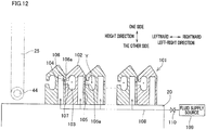
- an interlacing device 101 is formed of interlacing pieces 102 lined up in the left-right direction, as shown in FIG. 12 .
- the interlacing device 101 includes yarn running spaces 103, yarn introduction passages 104, and injection passages 105.
- the yarn running space 103 is substantially elliptical in shape and is long in the height direction when viewed in the yarn running direction.
- the yarn introduction passage 104 includes a first yarn passage 106 and a second yarn passage 107.
- the first yarn passage 106 is a gap between two neighboring interlacing pieces 102.
- the first yarn passage 106 extends in the height direction, and one end in the height direction of the first yarn passage 106 is an insertion slot 106a from which the yarn Y is inserted.
- the second yarn passage 107 is connected to the other end of the first yarn passage 106 in the height direction, extends rightward from the junction with the first yarn passage 106, and is connected to the yarn running space 103 at the right end.
- the injection passage 105 is formed in each interlacing piece 102 and extends in the height direction. At an upper end portion of the injection passage 105, an injection port 105a is formed to open in the left inner wall surface of the first yarn passage 106. With this arrangement, the injection port 105a of each interlacing piece 102 opposes, in the left-right direction, the yarn running space 103 of the interlacing piece 102 which is directly to the right of the each interlacing piece 102.
- the injection passage 105 is connected to a fluid supply source 109 via a fluid supply path 108.
- a valve 110 is provided on the fluid supply path 108. When the valve 110 is opened, fluid such as air supplied from the fluid supply source 109 is injected into the yarn running space 103 from the injection port 105a. As a result, a swirling flow is generated in the yarn running space 103, and the yarn Y is interlaced.
- the yarn introduction passage may include only the first yarn passage, and the first yarn passage may be directly connected to the yarn running space.
- the yarn Y is introduced into the yarn running space via the first yarn passage.
- a movement member for moving the yarn Y in the left-right direction is unnecessary, when an insertion member pressing the yarn Y in the height direction to insert the same into the first yarn passage is provided.
Landscapes
- Physics & Mathematics (AREA)
- Fluid Mechanics (AREA)
- Engineering & Computer Science (AREA)
- Textile Engineering (AREA)
- Yarns And Mechanical Finishing Of Yarns Or Ropes (AREA)
Abstract
Description
- The present invention relates to an interlacing device configured to interlace yarns.
- Patent Literature 1 (Japanese Unexamined Patent Publication No.
2016-160550 Patent Literature 1, a yarn is introduced into each yarn running space through a slit (equivalent to a first yarn passage of the present invention) which extends in the up-down direction and a yarn insertion gap (equivalent to a second yarn passage of the present invention) which is connected to the lower end of the slit and extends horizontally. - In the spun yarn take-up apparatus including the interlacing device recited in
Patent Literature 1, for example, insertion of a yarn into the slit of the interlacing device is prohibited, and after yarn threading to parts other than the interlacing device of the spun yarn take-up apparatus is completed, the prohibition is canceled, and the yarn is introduced into the yarn running space via the slit and the yarn insertion gap, by utilizing the tension of the yarn. However, in this case, at least some of the yarns may not be inserted into the slits even after the prohibition of insertion of yarns into the slit is canceled. The yarns not inserted into the slits are not introduced into the yarn running spaces. In such a case, the yarns must be manually introduced into the yarn running spaces by an operator. - An object of the present invention is to provide an interlacing device in which a yarn is certainly inserted into a yarn introduction passage through which the yarns is introduced into a yarn running space.
- According to the first aspect of the invention, an interlacing device includes: an interlacing portion configured to interlace a yarn; and a yarn introduction device configured to introduce the yarn into the interlacing portion, the interlacing portion including: a yarn running space in which the yarn runs; an injection unit configured to inject air into the yarn running space; and a yarn introduction passage through which the yarn is introduced into the yarn running space, the yarn introduction passage including a first yarn passage which extends in a first direction orthogonal to a yarn running direction in the yarn running space and has a yarn insertion slot at an end on one side in the first direction, and the yarn introduction device including an insertion member which presses the yarn from the one side toward the other side in the first direction to insert the yarn into the first yarn passage through the insertion slot.
- According to this aspect, as the yarn is pressed from the one side toward the other side in the first direction by the insertion member, the yarn is certainly inserted into the first path extending in the first direction.
- According to the second aspect of the invention, the interlacing device of the first aspect is arranged such that, the yarn introduction passage further includes a second yarn passage which is connected to an end of the first yarn passage on the other side in the first direction and extends along a second direction which is orthogonal to the yarn running direction and intersects with the first direction, and the yarn introduction device further includes a movement member which presses, in the second direction, the yarn inserted in the first yarn passage to move the yarn along the second yarn passage.
- After the yarn is inserted into the first yarn passage by the insertion member, the yarn having been inserted into the first yarn passage may be caught in the second yarn passage. According to the aspect above, as the yarn inserted into the first yarn passage is pressed in the second direction by the movement member, the yarn moves along the second yarn passage extending in the second direction.
- According to the third aspect of the invention, the interlacing device of the second aspect is arranged such that the yarn introduction device includes a common member which functions as both the insertion member and the movement member and is configured to press the yarn by exerting force including a component in the first direction and a component in the second direction to the yarn.
- According to this aspect, because the common member functioning as both the insertion member and the movement member is provided, the structure of the interlacing device is simple as compared to cases where the insertion member and the movement member are independently provided.
- According to the fourth aspect of the invention, the interlacing device of the third aspect is arranged such that the common member is a swing member which is swung to press the yarn.
- According to this aspect, force having a component in the first direction and a component in the second direction can be applied to the yarn Y by the swing member which has a simple structure.
- According to the fifth aspect of the invention, the interlacing device of the fourth aspect is arranged such that the swing member is swung about a shaft which is parallel to the yarn running direction.
- According to this aspect, because the swing member is swung about the shaft parallel to the yarn running direction, the length of a space required to provide the swing member is short in the yarn running direction, and hence the interlacing device is downsized in the yarn running direction.
- According to the sixth aspect of the invention, the interlacing device of any one of the second to fifth aspects is arranged such that the yarn introduction passage further includes a third yarn passage which is connected to an end of the second yarn passage opposite to the first yarn passage, and extends toward the one side in the first direction from a junction with the second yarn passage.
- According to this aspect, as the yarn is pressed by the insertion member and the movement member, the yarn is moved to the junction between the second yarn passage and the third yarn passage. Thereafter, as the pressing of the yarn by the insertion member and the movement member is canceled, the yarn moves in the third yarn passage and reaches the yarn running space, on account of the tension of itself.
- According to the seventh aspect of the invention, the interlacing device of any one of the first to sixth aspects is arranged such that the yarn introduction device is provided upstream of at least the interlacing portion in the yarn running direction.
- According to this aspect, as a yarn part upstream of the interlacing portion in the yarn running direction is pressed by the yarn introduction device, the yarn is inserted into the first yarn passage. When a running yarn is pressed by the yarn introduction device, a pressed part of the yarn is temporarily restricted. On this account, a part downstream of the pressed part of the yarn temporarily has increased tension, with the result that the yarn path becomes stable. Meanwhile, a part upstream of the pressed part of the yarn temporarily has decreased tension and is slackened, with the result that the yarn path becomes unstable. According to the aspect above, because the yarn introduction device is provided upstream of the interlacing portion in the yarn running direction, a yarn part with a stable yarn path, which is downstream of a part of the yarn pressed by the yarn introduction device, is introduced into the interlacing portion. On this account, according to the aspect above, the yarn is easily introduced to the interlacing portion as compared to cases where the yarn introduction device is provided downstream of the interlacing portion in the yarn running direction.
- According to the eighth aspect of the invention, the interlacing device of the seventh aspect further includes a yarn guide which is provided upstream of the interlacing portion in the yarn running direction, the yarn introduction device being provided at least between the interlacing portion and the yarn guide in the yarn running direction.
- When the yarn guide is provided upstream of the interlacing portion and the yarn introduction device is provided upstream of the yarn guide in the yarn running direction, the movement of the yarn in the interlacing portion when the yarn is pressed by the yarn introduction device may be obstructed by the yarn guide. According to the aspect above, the yarn introduction device is provided between the interlacing portion and the yarn guide in the yarn running direction. On this account, the movement of the yarn in the interlacing portion is not obstructed by the yarn guide when the yarn is pressed by the yarn introduction device.
- The present invention makes it possible to certainly introduce the yarn into the yarn introduction passage.
-
-
FIG. 1 is a schematic diagram of a spun yarn take-up apparatus. -
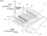
FIG. 2 is a perspective view showing the outline of an interlacing device. -
FIG. 3 shows the interlacing device ofFIG. 2 when viewed from one side in the height direction. -
FIG. 4 shows the interlacing device ofFIG. 2 when viewed from the right side. -
FIG. 5 is a cross section of a part of an interlacing portion taken along a plane which is parallel to the left-right direction and the height direction. -
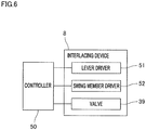
FIG. 6 is a block diagram illustrating an electric structure of the interlacing device and a controller. -
FIG. 7 corresponds toFIG. 3 and shows a state in yarn threading. -
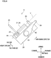
FIG. 8 corresponds toFIG. 4 and shows a state in yarn threading. -
FIG. 9 corresponds toFIG. 3 and shows a state in which a yarn regulation bar is returned to a regulation cancellation position and a swing member is moved to a pressing completion position. -
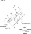
FIG. 10 corresponds toFIG. 4 and shows a state in which the yarn regulation bar is returned to the regulation cancellation position and the swing member is moved to the pressing completion position. -
FIG. 11(a) shows a state in which a yarn outside a yarn introduction passage is pressed by a swing member.FIG. 11(b) shows a state in which a yarn in a first yarn passage is pressed by the swing member.FIG. 11(c) shows a state in which a yarn in a second yarn passage is pressed by the swing member.FIG. 11(d) shows a state in which a yarn in a third yarn passage and a yarn running space is pressed by the swing member. -
FIG. 12 relates to an interlacing portion of a modification and corresponds toFIG. 5 . - The following will describe a preferred embodiment of the present invention.
- As shown in
FIG. 1 , a spun yarn take-up apparatus 1 takes up synthetic fiber yarns Y spun out from a spinning apparatus 2 and formed of filaments f, and forms packages P by winding the yarns Y onto bobbins B, respectively. The description below is given on the premise that the up-down direction, front-back direction, and left-right direction inFIG. 1 are respectively the up-down direction relative to the spun yarn take-up apparatus 1, the front-back direction relative to the spun yarn take-up apparatus 1, and the left-right direction relative to the spun yarn take-up apparatus 1. - The spun yarn take-
up apparatus 1 includes members such as acooling unit 3, anoil supply unit 4, adrawing unit 5, take-up rollers winding device 9. In the spinning apparatus 2, polymer supplied from a polymer supplier (not illustrated), which is a gear pump, for example, is extruded downward throughspinnerets 2a which are lined up in the left-right direction (the direction away from the viewer ofFIG. 1 ). As a consequence, yarns Y formed of filaments F are spun out while being lined up in the left-right direction. - The yarns Y spun out from the
spinnerets 2a of the spinning apparatus 2 travel along a yarn path through thecooling unit 3, theoil supply unit 4, thedrawing unit 5, the take-up roller 6, theinterlacing device 8, and the take-up roller 7, while being lined up in the left-right direction. The yarns Y are distributed in the front-back direction from the take-up roller 7, and are then wound onto the bobbins B at thewinding device 9. - The
cooling unit 3 includes a plurality ofcylindrical cooling cylinders 10. Each coolingcylinder 10 is provided below the correspondingspinneret 2a of the spinning apparatus 2. The yarns Y spun out from thespinnerets 2a of the spinning apparatus 2 run downward ininternal spaces 10a of the coolingcylinders 10, along the axial direction of thecooling cylinder 10. Aflow adjustment section 10b is provided around theinternal space 10a. Cooling wind supplied from an unillustrated pressurized air supplier flows into theinternal space 10a while being adjusted by theflow adjustment section 10b. Theflow adjustment section 10b mainly performs the adjustment in such a way that the flow rate of the cooling wind flowing into theinternal space 10a is more or less even in the circumferential direction of thecooling cylinder 10. - The
oil supply unit 4 includes oil supply guides 11 which are provided below therespective cooling cylinders 10. Theoil supply guide 11 gathers filaments F spun out from thespinneret 2a into a single yarn Y, and applies oil to the yarn Y (filaments F). - The
drawing unit 5 is provided below theoil supply unit 4. Thedrawing unit 5 includes: aheat retaining box 12; and heating rollers (not illustrated) accommodated in theheat retaining box 12. By the heating rollers, thedrawing unit 5 draws the yarns Y while heating them. - The yarns Y drawn by the
drawing unit 5 are sent to the windingdevice 9 by the take-uprollers device 8 is provided between the take-uproller 6 and the take-uproller 7 to interlace filaments F constituting each yarn Y. The details of the interlacingdevice 8 will be given later. - The winding
device 9 includes members such as aframe 13, aturret 14, twobobbin holders 15, a supportingframe 16, acontact roller 17, and atraverse unit 18. The windingdevice 9 simultaneously winds the yarns Y sent from the take-uproller 7 onto the bobbins B by rotating thebobbin holder 15, so as to form packages P. - The
turret 14 is a disc-shaped member and is attached to theframe 13. Theturret 14 is rotationally driven by a motor which is not illustrated. The twobobbin holders 15 are cantilevered by theturret 14 to extend in the front-back direction. To eachbobbin holder 15, cylindrical bobbins B are attached to be lined up along the axial direction of thebobbin holder 15. As theturret 14 rotates, the positions of the twobobbin holders 15 are switched between an upper winding position and a lower retracted position. - The supporting
frame 16 is a frame-shaped member which is long in the front-back direction. This supportingframe 16 is fixed to theframe 13. Aroller supporting member 19 which is long in the front-back direction is attached to a lower part of the supportingframe 16 so as to be vertically movable relative to the supportingframe 16. Theroller supporting member 19 supports thecontact roller 17 in a rotatable manner. Thecontact roller 17 extends in the axial direction of thebobbin holders 15. As thiscontact roller 17 makes contact with a package P under the formation and thecontact roller 17 applies a predetermined contact pressure to the package P, the shape of the package P is adjusted. - The
traverse unit 18 includes traverse guides 18a lined up in the front-back direction. The traverse guides 18a are driven by a motor (not illustrated) and are configured to reciprocate in the front-back direction. As eachtraverse guide 18a to which the yarn Y is threaded reciprocates, the yarn Y is wound onto the corresponding bobbin B while being traversed about afulcrum guide 18b. - Now, the interlacing
device 8 will be detailed. As shown inFIG. 2 to FIG. 5 , the interlacingdevice 8 includes abase 20, an interlacingportion 21, upstream yarn guides 22, downstream yarn guides 23, ayarn regulation bar 24, and a swing member 25 (a common member of the present invention). In the interlacingdevice 8, yarns Y run in a yarn running direction which is inclined relative to the front-back direction so as to be a positive slope in the rearward direction. Furthermore, hereinafter, a direction orthogonal to both the yarn running direction and the left-right direction (a second direction in the present invention) is defined as a height direction of the interlacing device 8 (a first direction in the present invention), and one side and the other side in the height direction are defined as shown inFIG. 2 . - The
base 20 is substantially rectangular parallelepiped in shape. An interlacingportion 21 is constructed such that interlacingpieces 26 are lined up in the left-right direction on a surface of the base 20 on one side in the height direction. The interlacingportion 21 includesyarn running spaces 31,yarn introduction passages 32, andinjection passages 33. Theyarn running spaces 31 are formed in the respective interlacingpieces 26. Theyarn running space 31 is substantially elliptical in shape and is long in the left-right direction when viewed in the yarn running direction. In the yarn running direction, theyarn running space 31 extends over the entire length of the interlacingpiece 26 and is open at the both ends. - The
yarn introduction passages 32 are passages provided for the respectiveyarn running spaces 31 to introduce the yarns Y to theyarn running spaces 31. In the yarn running direction, theyarn introduction passage 32 extends over the entire length of the interlacingpiece 26 and is open at the both ends. Theyarn introduction passage 32 includes afirst yarn passage 36, asecond yarn passage 37, and athird yarn passage 38. - The
first yarn passage 36 is a gap formed between two neighboring interlacingpieces 26, and extends in the height direction at a substantially upper half of the interlacingpiece 26. One end in the height direction of thefirst yarn passage 36 is aninsertion slot 36a from which the yarn Y is inserted. - The
second yarn passage 37 is connected to the other end of thefirst yarn passage 36 in the height direction, and extends rightward from the junction with thefirst yarn passage 36. Thethird yarn passage 38 is connected to the right end of thesecond yarn passage 37, and extends toward the one side in the height direction from the junction with thesecond yarn passage 37. An end on the one side in the height direction of thethird yarn passage 38 is connected to theyarn running space 31. - A substantial left half of the surface on the one side in the height direction of the interlacing
piece 26 is aninclined surface 26a which is inclined relative to the left-right direction so as to be a negative slope in the leftward direction if it is assumed that the height direction is the vertical direction. A substantial right half of the surface on the one side in the height direction of the interlacingpiece 26 is aninclined surface 26b which is inclined relative to the left-right direction so as to be a negative slope in the rightward direction if it is assumed that the height direction is the vertical direction. As such, theinclined surfaces first yarn passage 36 in the left-right direction, and the yarn Y is guided by theinclined surfaces first yarn passage 36. - The
injection passages 33 are provided for the respectiveyarn running spaces 31. Oneinjection passage 33 is formed for each interlacingpiece 26 and extends in the height direction. A leading end (end on the one side) of theinjection passage 33 is aninjection port 33a which is open to a wall surface of the junction between thesecond yarn passage 37 and thethird yarn passage 38, on the other side in the height direction. Theinjection port 33a therefore opposes theyarn running space 31 across thethird yarn passage 38 in the height direction. A lower end portion of theinjection passage 33 is connected to afluid supply source 40 via afluid supply path 41. Avalve 39 is provided on thefluid supply path 41. When thevalve 39 is opened, fluid such as air supplied from thefluid supply source 40 is supplied to theinjection passage 33 via thefluid supply path 41, and is injected into theyarn running space 31 from theinjection port 33a of theinjection passage 33. As a result, a swirling flow is generated in theyarn running space 31, and the filaments F forming the yarn Y running in theyarn running space 31 are interlaced. - In the present embodiment, a combination of the
injection passage 33, thefluid supply source 40, thefluid supply path 41, and thevalve 39 is equivalent to an injection unit of the present invention. - The upstream yarn guides 22 are provided upstream of the interlacing
portion 21 in the yarn running direction and on the surface of the base 20 on the one side in the height direction, and are lined up in the left-right direction. Eachupstream yarn guide 22 is a column extending in the height direction. The downstream yarn guides 23 are provided downstream of the interlacingportion 21 in the yarn running direction and on the surface of the base 20 on the one side in the height direction, and are lined up in the left-right direction. Eachdownstream yarn guide 23 is a column similar to theupstream yarn guide 22. The upstream yarn guides 22 and the downstream yarn guides 23 are substantially symmetrical in position in the left-right direction. Because the yarn Y running in the yarn running direction passes between the neighboring upstream yarn guides 22 and between the neighboring downstream yarn guides 23, the movement of the yarn Y in the left-right direction is regulated, and the yarn path is defined. The yarn guides 22 and 23 have a function of supporting the yarn Y when the yarn Y is interlaced at the interlacingportion 21. - As described below, the
yarn regulation bar 24 prevents the yarn Y from being introduced into theyarn running space 31 at the time of yarn threading to the spun yarn take-upapparatus 1. Theyarn regulation bar 24 is a substantially columnar member which extends in the left-right direction over the interlacing pieces 26 (the upstream yarn guides 22 and the downstream yarn guides 23) and has an axis extending in the left-right direction. Theyarn regulation bar 24 is cantilevered at a leading end portion of alever 42. Thelever 42 is swingable about ashaft 43 extending in the left-right direction, and is swung about theshaft 43 by a lever driver 51 (seeFIG. 6 ). When the yarns Y having been spun out are taken up in the spun yarn take-upapparatus 1, as shown inFIG. 2 to FIG. 4 , theyarn regulation bar 24 is positioned downstream in the yarn running direction of the downstream yarn guides 23 and is on the other side in the height direction of the yarn paths in the interlacingdevice 8. (Hereinafter, this position may be referred to as a regulation cancellation position.) When theyarn regulation bar 24 is at the regulation cancellation position, theyarn regulation bar 24 does not interfere with the yarns Y and does not prevent the yarns Y from entering theyarn running spaces 31. - As described below, the
swing member 25 is provided to introduce the yarns Y into theyarn running spaces 31. Theswing member 25 is a long plate-shaped member. The length of theswing member 25 is longer than the interlacingportion 21 in the left-right direction. Theswing member 25 is positioned between the interlacingportion 21 and the upstream yarn guides 22 in the yarn running direction. Theswing member 25 is swingable about ashaft 44 which is to the left of the interlacing pieces 26 (the upstream yarn guides 22 and the downstream yarn guides 23) and is parallel to the yarn running direction. Theswing member 25 is swung about theshaft 44 by a swing member driver 52 (seeFIG. 6 ). When the yarns Y having been spun out are taken up in the spun yarn take-upapparatus 1, as shown inFIG. 2 to FIG. 5 , theswing member 25 is postured so that the length thereof is substantially parallel to the height direction, and is at a position out of the yarn paths of the interlacing device 8 (hereinafter, this position may be referred to as a pressing cancellation position). Theswing member 25 at the pressing cancellation position does not interfere with the yarns Y running in the interlacingdevice 8. - In the present embodiment, as shown in
FIG. 6 , thecontroller 50 controls operations of thelever driver 51, theswing member driver 52, and thevalve 39 of the interlacingdevice 8. - Now, a method of performing yarn threading to the spun yarn take-up
apparatus 1 will be described. In the spun yarn take-upapparatus 1, after yarn threading to theoil supply guide 11, the heating roller of thedrawing unit 5, and the take-uprollers yarn running space 31 and yarn threading to the yarn guides 22 and 23) is performed. Subsequently, yarn threading to the fulcrum guides 18b and the bobbins B is performed. - Before the yarn threading to parts other than the interlacing
device 8 in the spun yarn take-upapparatus 1, thecontroller 50 controls thelever driver 51 to swing thelever 42, with the result that theyarn regulation bar 24 is at a position (hereinafter, this position may be referred to as a regulation position) which is on one side in the height direction of the interlacingportion 21, as shown inFIG. 7 andFIG. 8 . Thereafter, the operator performs yarn threading to the parts other than the interlacingdevice 8 in the spun yarn take-upapparatus 1. In so doing, the operator places the yarns onto theyarn regulation bar 24. On this account, at the time of the yarn threading to the parts other than the interlacingdevice 8 in the spun yarn take-upapparatus 1, yarn threading of the yarns Y to the interlacing device 8 (i.e., introduction of the yarn into theyarn running space 31 and yarn threading to the yarn guides 22 and 23) is prohibited by theyarn regulation bar 24. - After the yarn threading to the parts other than the interlacing
device 8 in the spun yarn take-upapparatus 1 is completed, thecontroller 50 controls thelever driver 51 to swing thelever 42, with the result that theyarn regulation bar 24 returns from the regulation position to the regulation cancellation position, as shown inFIG. 9 andFIG. 10 . Thereafter, thecontroller 50 controls theswing member driver 52 to swing theswing member 25 from the pressing cancellation position to a position (hereinafter, this position may be referred to as a pressing completion position) where the length of theswing member 25 is substantially parallel to the left-right direction. Subsequently, thecontroller 50 controls theswing member driver 52 to return theswing member 25 from the pressing completion position to the pressing cancellation position. - When the
yarn regulation bar 24 is returned to the regulation cancellation position, the regulation of the yarns Y by theyarn regulation bar 24 is canceled, and the yarns Y are threaded to the upstream yarn guides 22 and the downstream yarn guides 23 on account of the tensions of the yarns Y. At this stage, a part of each yarn Y, which is above the interlacingportion 21, moves on account of the tension T of itself. The tension T is force exerted toward theyarn running space 31. As a result of this movement of the yarns Y, all yarns Y may be introduced into theyarn running spaces 31. However, at least some of the yarns Y may be outside theyarn introduction passages 32 as they are caught on one of theinclined surfaces yarn introduction passages 32. - Thereafter, when the
swing member 25 is moved from the pressing cancellation position to the pressing completion position, the yarns Y are pressed by theswing member 25. In this connection, before reaching the pressing completion position, theswing member 25 makes contact with and presses the yarns Y, while the length of theswing member 25 is inclined relative to the left-right direction. On this account, as shown inFIG. 11(a) to FIG. 11(d) , the pressing force E with which theswing member 25 presses the yarn Y includes a component E1 (hereinafter, a component E1 in the height direction) exerted from the one side to the other side in the height direction and a component E2 (hereinafter, a component E2 in the left-right direction) exerted from the left side to the right side. - Therefore, as shown in
FIG. 11(a) , when pressed by theswing member 25, the yarn Y outside theyarn introduction passage 32 is inserted into thefirst yarn passage 36 through theinsertion slot 36a, mainly on account of the component E1 in the height direction of the pressing force E. Furthermore, as shown inFIG. 11(b) , when pressed by theswing member 25, the yarn Y inside thefirst yarn passage 36 is moved to the junction between thefirst yarn passage 36 and thesecond yarn passage 37, mainly on account of the component E1 in the height direction of the pressing force E. - Furthermore, as shown in
FIG. 11(c) , when pressed by theswing member 25, the yarn Y either at the junction between thefirst yarn passage 36 and thesecond yarn passage 37 or in thesecond yarn passage 37 is moved to the junction between thesecond yarn passage 37 and thethird yarn passage 38, on account of the component E2 in the left-right direction of the pressing force E and the tension T. - Furthermore, as shown in
FIG. 11(d) , when pressed by theswing member 25, the yarn Y in thethird yarn passage 38 and theyarn running space 31 is moved to the junction between thesecond yarn passage 37 and thethird yarn passage 38, mainly on account of the component E1 in the height direction of the pressing force E. - In this way, when the
swing member 25 reaches the pressing completion position, all yarns Y have been moved to the junction between thesecond yarn passage 37 and thethird yarn passage 38 as shown inFIG. 11(d) . - Thereafter, the pressing of the yarns Y by the
swing member 25 is canceled as theswing member 25 is returned from the pressing completion position to the pressing cancellation position. As a result, the yarn Y having been moved to the junction between thesecond yarn passage 37 and thethird yarn passage 38 is moved to the one side in the height direction in thethird yarn passage 38 on account of the tension T of itself, and is introduced into theyarn running space 31. - As described above, when the regulation by the
yarn regulation bar 24 is canceled after yarn threading to parts other than the interlacingdevice 8 of the spun yarn take-upapparatus 1 is performed, the yarns Y may be introduced into theyarn running spaces 31 on account of their tensions, but some of the yarn Y may not be introduced into theyarn running spaces 31 because, for example, they are not inserted into theyarn introduction passages 32 or caught in theyarn introduction passages 32. For this reason, in the present embodiment, the yarns Y are pressed by theswing member 25 after the cancelation of the regulation by theyarn regulation bar 24, and then the pressing of the yarns Y by theswing member 25 is canceled. This causes all yarns Y to be introduced into theyarn running spaces 31. - In the present embodiment, the
yarn introduction passage 32 includes thefirst yarn passage 36 extending in the height direction, thesecond yarn passage 37 connected to thefirst yarn passage 36 and extending in the left-right direction, and thethird yarn passage 38 connected to thesecond yarn passage 37 and extending in the height direction. On this account, to reach theyarn running space 31, the yarn Y is required to move in thefirst yarn passage 36 in the height direction and then change the moving direction and move in thesecond yarn passage 37 in the left-right direction, and further change the moving direction and move in thethird yarn passage 38 in the height direction. The yarn Y is therefore likely to be caught before reaching theyarn running space 31 if the yarn Y is moved solely by the tension of itself. - In this regard, in the present embodiment, as the yarn Y is pressed by the
swing member 25, pressing force E having the component E1 in the height direction and the component E2 in the left-right direction is applied to the yarn Y. With this arrangement, as described above, the yarn Y pressed by theswing member 25 moves in thefirst yarn passage 36 and in thesecond yarn passage 37 in order, and reaches the junction between thesecond yarn passage 37 and thethird yarn passage 38. Thereafter, as the pressing of the yarn Y by theswing member 25 is canceled, the yarn Y moves in thethird yarn passage 38 and reaches theyarn running space 31, on account of the tension of itself. - In regard to the above, in the present embodiment, because one
swing member 25 exerts the pressing force E having the component E1 in the height direction and the component E2 in the left-right direction to the yarn Y, the structure of the interlacingdevice 8 is simple as compared to cases where a member which presses the yarn Y in the height direction to insert the yarn Y into thefirst yarn passage 36 and a moving member which presses the yarn Y in the left-right direction to move the yarn Y in the left-right direction are independently provided. - In the present embodiment, as the yarn Y is pressed by the
swing member 25 which is swung about theshaft 44, the pressing force E having a component E1 in the height direction and a component E2 in the left-right direction can be applied to the yarn Y by a simple structure. In this connection, because theshaft 44 is parallel to the yarn running direction, the length of a space required to swing theswing member 25 is short in the yarn running direction, and hence the interlacingdevice 8 is downsized in the yarn running direction. - In addition to the above, when the
swing member 25 presses a running yarn Y, a pressed part of the yarn Y is temporarily restricted. On this account, a part downstream of the pressed part of the yarn Y temporarily has increased tension, with the result that the yarn path becomes stable. Meanwhile, a part upstream of the pressed part of the yarn Y temporarily has decreased tension and is slackened, with the result that the yarn path becomes unstable. For this reason, in the present embodiment, theswing member 25 is provided upstream of the interlacingportion 21 in the yarn running direction. With this arrangement, a yarn part with a stable yarn path, which is downstream of a part of the yarn pressed by theswing member 25 in the yarn running direction, is introduced into the interlacingportion 21. The yarn Y is therefore easily introduced into the interlacingportion 21, as compared to cases where theswing member 25 is provided downstream of the interlacingportion 21. - Being different from the present embodiment, assume that the
swing member 25 is provided upstream of the upstream yarn guides 22 in the yarn running direction. In such a case, because the upstream yarn guides 22 are provided between theswing member 25 and the interlacingportion 21, the movement of a part of the yarn Y running at the interlacingportion 21 may be obstructed by theupstream yarn guide 22 when the yarn Y is pressed by theswing member 25. - In this regard, in the present embodiment, the
swing member 25 is provided between the interlacingportion 21 and the upstream yarn guides 22 in the yarn running direction. On this account, the movement of the yarn Y in the interlacingportion 21 is not obstructed by theupstream yarn guide 22 when the yarn Y is pressed by theswing member 25. - A preferred embodiment of the present invention has been described. It should be noted that the present invention is not limited to the above-described embodiment, and various changes, substitutions, and alterations can be made herein without departing from the spirit and scope of the invention as defined by the appended claims.
- While in the embodiment above the upstream yarn guides 22 are provided upstream of the interlacing
portion 21 in the yarn running direction and theswing member 25 is provided between the upstream yarn guides 22 and the interlacingportion 21, the disclosure is not limited to this arrangement. For example, when the interlacingdevice 8 includes only the downstream yarn guides 23 among the upstream yarn guides 22 and the downstream yarn guides 23, theswing member 25 may be provided upstream of the interlacingportion 21 in the yarn running direction. - While in the embodiment above the
swing member 25 is provided upstream of the interlacingportion 21 in the yarn running direction, the disclosure is not limited to this arrangement. For example, theswing member 25 may be provided downstream of the interlacingportion 21 in the yarn running direction. Alternatively,swing members 25 are provided both upstream and downstream of the interlacingportion 21 in the yarn running direction. - When the
swing member 25 is provided downstream of the interlacingportion 21 in the yarn running direction, if the interlacingdevice 8 includes a plurality of downstream yarn guides 23 as in the embodiment above, theswing member 25 may be provided between the interlacingportion 21 and the downstream yarn guides 23 in the yarn running direction. With this arrangement, the movement of the yarn Y in the interlacingportion 21 is not obstructed by thedownstream yarn guide 23 when the yarn Y is pressed by theswing member 25. - While in the embodiment above the
swing member 25 is swingable about theshaft 44 which is parallel to the yarn running direction, the disclosure is not limited to this arrangement. Theswing member 25 may be swingable about a shaft which is slightly inclined relative to the yarn running direction. - While in the embodiment above the yarn Y is pressed by the
swingable swing member 25, the disclosure is not limited to this arrangement. For example, the yarn Y may be pressed by a member (the common member of the present invention) which moves in a parallel manner in a direction orthogonal to the yarn running direction and intersecting with the height direction and the left-right direction. Also in this case, pressing force having a component in the height direction and a component in the left-right direction can be applied to the yarn Y. - While, in the embodiment above, force having a component in the height direction and a component in the left-right direction is applied to the yarn Y by one
swing member 25, the disclosure is not limited to this arrangement. For example, in the embodiment above, an insertion member which presses the yarn Y in the height direction to insert the yarn Y into thefirst yarn passage 36 through theinsertion slot 36a and a movement member which presses, in the left-right direction, the yarn Y inserted into thefirst yarn passage 36 to move the yarn Y in the left-right direction along thesecond yarn passage 37 may be independently provided instead of the swing member. The insertion member is, for example, a long member which extends parallel to the left-right direction and over the interlacingpieces 26, and moves in a parallel manner in the height direction. The movement member may be a comb-teeth member, for example. Alternatively, at least one set of the yarn guides 22 and 23 may be arranged to be movable in the left-right direction as a movement member. - In addition to the above, the yarn Y may not be pressed by force having a component in the height direction and a component in the left-right direction. For example, a movement member for moving the yarn Y in the left-right direction may not be provided when an insertion member pressing the yarn Y in the height direction to insert the same into the first yarn passage is provided. In this case, a yarn Y which is not inserted into the first yarn passage and a yarn Y caught in the first yarn passage are pressed by the insertion member and moved to the junction between the first yarn passage and the second yarn passage. With this arrangement, thereafter, movement of the yarn Y along the second yarn passage on account of its tension is facilitated. The yarn Y is therefore likely to be introduced into the
yarn running space 31 as compared to cases where no insertion member is provided. - While in the embodiment above the
second yarn passage 37 extends to be parallel to the left-right direction orthogonal to the height direction in which thefirst yarn passage 36 extends, the disclosure is not limited to this arrangement. Thesecond yarn passage 37 may extend in a direction which is orthogonal to the running direction in the interlacingdevice 8 and is inclined relative to the left-right direction. - While in the embodiment above the
yarn introduction passage 32 through which the yarn is introduced into theyarn running space 31 includes thefirst yarn passage 36, thesecond yarn passage 37, and thethird yarn passage 38, the disclosure is not limited to this arrangement. - For example, according to a modification, an interlacing
device 101 is formed of interlacingpieces 102 lined up in the left-right direction, as shown inFIG. 12 . The interlacingdevice 101 includesyarn running spaces 103,yarn introduction passages 104, andinjection passages 105. - The
yarn running space 103 is substantially elliptical in shape and is long in the height direction when viewed in the yarn running direction. Theyarn introduction passage 104 includes afirst yarn passage 106 and asecond yarn passage 107. Thefirst yarn passage 106 is a gap between two neighboring interlacingpieces 102. Thefirst yarn passage 106 extends in the height direction, and one end in the height direction of thefirst yarn passage 106 is aninsertion slot 106a from which the yarn Y is inserted. Thesecond yarn passage 107 is connected to the other end of thefirst yarn passage 106 in the height direction, extends rightward from the junction with thefirst yarn passage 106, and is connected to theyarn running space 103 at the right end. - The
injection passage 105 is formed in each interlacingpiece 102 and extends in the height direction. At an upper end portion of theinjection passage 105, aninjection port 105a is formed to open in the left inner wall surface of thefirst yarn passage 106. With this arrangement, theinjection port 105a of each interlacingpiece 102 opposes, in the left-right direction, theyarn running space 103 of the interlacingpiece 102 which is directly to the right of the each interlacingpiece 102. Theinjection passage 105 is connected to afluid supply source 109 via afluid supply path 108. Avalve 110 is provided on thefluid supply path 108. When thevalve 110 is opened, fluid such as air supplied from thefluid supply source 109 is injected into theyarn running space 103 from theinjection port 105a. As a result, a swirling flow is generated in theyarn running space 103, and the yarn Y is interlaced. - In this interlacing
device 101, as thecontroller 50 controls theswing member driver 52 to swing theswing member 25 from the pressing cancellation position to the pressing completion position, pressing force including a component in the height direction and a component in the left-right direction is exerted to the yarn Y. Therefore, when pressed by theswing member 25, the yarn Y outside theyarn introduction passage 104 is inserted into thefirst yarn passage 106 through theinsertion slot 106a, mainly on account of the component in the height direction of the pressing force. Furthermore, when pressed by theswing member 25, the yarn Y inside thefirst yarn passage 106 is moved in thefirst yarn passage 106 and reaches the junction with thesecond yarn passage 107, mainly on account of the component in the height direction of the pressing force. Furthermore, when pressed by theswing member 25, the yarn Y inside thesecond yarn passage 107 is moved in thesecond yarn passage 107 and reaches theyarn running space 103, mainly on account of the component in the left-right direction of the pressing force. - Alternatively, the yarn introduction passage may include only the first yarn passage, and the first yarn passage may be directly connected to the yarn running space. In this case, as the yarn Y is pressed in the height direction, the yarn Y is introduced into the yarn running space via the first yarn passage. In this case, a movement member for moving the yarn Y in the left-right direction is unnecessary, when an insertion member pressing the yarn Y in the height direction to insert the same into the first yarn passage is provided.
Claims (8)
- An interlacing device comprising:an interlacing portion configured to interlace a yarn; anda yarn introduction device configured to introduce the yarn into the interlacing portion,the interlacing portion including:a yarn running space in which the yarn runs;an injection unit configured to inject air into the yarn running space; anda yarn introduction passage through which the yarn is introduced into the yarn running space,the yarn introduction passage includinga first yarn passage which extends in a first direction orthogonal to a yarn running direction in the yarn running space and has a yarn insertion slot at an end on one side in the first direction, andthe yarn introduction device includingan insertion member which presses the yarn from the one side toward the other side in the first direction to insert the yarn into the first yarn passage through the insertion slot.
- The interlacing device according to claim 1, wherein,
the yarn introduction passage further includes
a second yarn passage which is connected to an end of the first yarn passage on the other side in the first direction and extends along a second direction which is orthogonal to the yarn running direction and intersects with the first direction, and
the yarn introduction device further includes
a movement member which presses, in the second direction, the yarn inserted in the first yarn passage to move the yarn along the second yarn passage. - The interlacing device according to claim 2, wherein,
the yarn introduction device includes
a common member which functions as both the insertion member and the movement member and is configured to press the yarn by exerting force including a component in the first direction and a component in the second direction to the yarn. - The interlacing device according to claim 3, wherein, the common member is a swing member which is swung to press the yarn.
- The interlacing device according to claim 4, wherein, the swing member is swung about a shaft which is parallel to the yarn running direction.
- The interlacing device according to any one of claims 2 to 5, wherein,
the yarn introduction passage further includes
a third yarn passage which is connected to an end of the second yarn passage opposite to the first yarn passage, and extends toward the one side in the first direction from a junction with the second yarn passage. - The interlacing device according to any one of claims 1 to 6, wherein, the yarn introduction device is provided upstream of at least the interlacing portion in the yarn running direction.
- The interlacing device according to claim 7, further comprising
a yarn guide which is provided upstream of the interlacing portion in the yarn running direction,
the yarn introduction device being provided at least between the interlacing portion and the yarn guide in the yarn running direction.
Applications Claiming Priority (1)
| Application Number | Priority Date | Filing Date | Title |
|---|---|---|---|
| JP2017238801A JP7128572B2 (en) | 2017-12-13 | 2017-12-13 | Entangling device |
Publications (2)
| Publication Number | Publication Date |
|---|---|
| EP3498898A1 true EP3498898A1 (en) | 2019-06-19 |
| EP3498898B1 EP3498898B1 (en) | 2020-10-28 |
Family
ID=64362307
Family Applications (1)
| Application Number | Title | Priority Date | Filing Date |
|---|---|---|---|
| EP18203674.9A Active EP3498898B1 (en) | 2017-12-13 | 2018-10-31 | Interlacing device |
Country Status (3)
| Country | Link |
|---|---|
| EP (1) | EP3498898B1 (en) |
| JP (1) | JP7128572B2 (en) |
| CN (1) | CN109914000B (en) |
Cited By (3)
| Publication number | Priority date | Publication date | Assignee | Title |
|---|---|---|---|---|
| CN115233325A (en) * | 2022-09-23 | 2022-10-25 | 江苏恒力化纤股份有限公司 | A kind of method for producing special-shaped fiber with low filament rate by polyester FDY process |
| EP4279647A1 (en) * | 2022-05-19 | 2023-11-22 | TMT Machinery, Inc. | Apparatus for treating yarns comprising a threading device |
| CN117779223A (en) * | 2022-09-28 | 2024-03-29 | 日本Tmt机械株式会社 | Wire processing device |
Families Citing this family (1)
| Publication number | Priority date | Publication date | Assignee | Title |
|---|---|---|---|---|
| JP7580078B2 (en) * | 2021-02-16 | 2024-11-11 | Tmtマシナリー株式会社 | Intertwining device and yarn winding machine |
Citations (4)
| Publication number | Priority date | Publication date | Assignee | Title |
|---|---|---|---|---|
| EP2065495A2 (en) * | 2007-11-29 | 2009-06-03 | TMT Machinery, Inc. | Multiple yarn interlacing device |
| EP2407407A2 (en) * | 2010-07-13 | 2012-01-18 | TMT Machinery, Inc. | Yarn threading method of take-up winding apparatus, take-up winding apparatus, and suction gun |
| JP2016113716A (en) * | 2014-12-12 | 2016-06-23 | Tmtマシナリー株式会社 | Interlacing imparting mechanism |
| JP2016160550A (en) | 2015-03-02 | 2016-09-05 | Tmtマシナリー株式会社 | Interlacing device |
Family Cites Families (6)
| Publication number | Priority date | Publication date | Assignee | Title |
|---|---|---|---|---|
| JP3158709B2 (en) * | 1992-09-16 | 2001-04-23 | 東レ株式会社 | Nozzle for entanglement of yarn |
| JP2000017534A (en) * | 1998-06-24 | 2000-01-18 | Toray Eng Co Ltd | Yarn processing equipment |
| JP4673355B2 (en) * | 2007-10-30 | 2011-04-20 | Tmtマシナリー株式会社 | Confounding device |
| JP5398462B2 (en) * | 2009-10-15 | 2014-01-29 | Tmtマシナリー株式会社 | Yarn conveying device |
| JP5604080B2 (en) * | 2009-10-26 | 2014-10-08 | Tmtマシナリー株式会社 | Yarn entanglement device |
| CN205313759U (en) * | 2015-10-27 | 2016-06-15 | 汤浅丝道工业株式会社 | Hand over twine to form processing apparatus |
-
2017
- 2017-12-13 JP JP2017238801A patent/JP7128572B2/en active Active
-
2018
- 2018-10-26 CN CN201811256518.6A patent/CN109914000B/en active Active
- 2018-10-31 EP EP18203674.9A patent/EP3498898B1/en active Active
Patent Citations (4)
| Publication number | Priority date | Publication date | Assignee | Title |
|---|---|---|---|---|
| EP2065495A2 (en) * | 2007-11-29 | 2009-06-03 | TMT Machinery, Inc. | Multiple yarn interlacing device |
| EP2407407A2 (en) * | 2010-07-13 | 2012-01-18 | TMT Machinery, Inc. | Yarn threading method of take-up winding apparatus, take-up winding apparatus, and suction gun |
| JP2016113716A (en) * | 2014-12-12 | 2016-06-23 | Tmtマシナリー株式会社 | Interlacing imparting mechanism |
| JP2016160550A (en) | 2015-03-02 | 2016-09-05 | Tmtマシナリー株式会社 | Interlacing device |
Cited By (5)
| Publication number | Priority date | Publication date | Assignee | Title |
|---|---|---|---|---|
| EP4279647A1 (en) * | 2022-05-19 | 2023-11-22 | TMT Machinery, Inc. | Apparatus for treating yarns comprising a threading device |
| CN115233325A (en) * | 2022-09-23 | 2022-10-25 | 江苏恒力化纤股份有限公司 | A kind of method for producing special-shaped fiber with low filament rate by polyester FDY process |
| CN115233325B (en) * | 2022-09-23 | 2022-12-16 | 江苏恒力化纤股份有限公司 | Method for producing low-broken-yarn-rate profiled fibers by polyester FDY (fully drawn yarn) process |
| CN117779223A (en) * | 2022-09-28 | 2024-03-29 | 日本Tmt机械株式会社 | Wire processing device |
| EP4345039A1 (en) * | 2022-09-28 | 2024-04-03 | TMT Machinery, Inc. | Yarn processing apparatus |
Also Published As
| Publication number | Publication date |
|---|---|
| EP3498898B1 (en) | 2020-10-28 |
| CN109914000B (en) | 2022-04-26 |
| CN109914000A (en) | 2019-06-21 |
| JP2019105007A (en) | 2019-06-27 |
| JP7128572B2 (en) | 2022-08-31 |
Similar Documents
| Publication | Publication Date | Title |
|---|---|---|
| EP3498898B1 (en) | Interlacing device | |
| EP2407408B1 (en) | Filament yarn winding apparatus | |
| JP7613888B2 (en) | Blended yarn manufacturing equipment | |
| JP5642441B2 (en) | Threading method for spinning winder, spinning winder, and suction gun | |
| JP6495051B2 (en) | Confounding device | |
| US8152090B2 (en) | Take-up device | |
| EP3835468B1 (en) | Yarn handling device | |
| JP7549999B2 (en) | Oil recovery device, yarn processing mechanism and yarn take-up device | |
| EP3521486A1 (en) | Oil supply guide and spun yarn take-up apparatus | |
| CN109402824B (en) | Interlacing device | |
| JP2016513758A (en) | Equipment for melt spinning, drawing and winding a plurality of synthetic yarns | |
| JP2007512444A (en) | Spinning equipment | |
| JP6027344B2 (en) | Textile machinery | |
| EP3210919B1 (en) | Spun yarn take-up machine | |
| JP6334373B2 (en) | Confounding device | |
| JP6352793B2 (en) | Confounding mechanism | |
| CN1416479A (en) | Parallel spinning process invilving intermingling of threads between galettet and corresponding spinning installation therefor | |
| JP7772901B2 (en) | Spinning production equipment | |
| EP4411034A1 (en) | Yarn production system | |
| JP2023023618A (en) | Yarn processing mechanism and spinning takeoff device | |
| EP4411035A1 (en) | Yarn production system | |
| CN115467037B (en) | Spinning traction device | |
| EP4596767A1 (en) | Interlacing apparatus and spun yarn take-up machine | |
| EP4345039A1 (en) | Yarn processing apparatus | |
| JPH11229229A (en) | Spinning take-up device and method of hooking yarn to spinning take-up device |
Legal Events
| Date | Code | Title | Description |
|---|---|---|---|
| PUAI | Public reference made under article 153(3) epc to a published international application that has entered the european phase |
Free format text: ORIGINAL CODE: 0009012 |
|
| STAA | Information on the status of an ep patent application or granted ep patent |
Free format text: STATUS: THE APPLICATION HAS BEEN PUBLISHED |
|
| AK | Designated contracting states |
Kind code of ref document: A1 Designated state(s): AL AT BE BG CH CY CZ DE DK EE ES FI FR GB GR HR HU IE IS IT LI LT LU LV MC MK MT NL NO PL PT RO RS SE SI SK SM TR |
|
| AX | Request for extension of the european patent |
Extension state: BA ME |
|
| STAA | Information on the status of an ep patent application or granted ep patent |
Free format text: STATUS: REQUEST FOR EXAMINATION WAS MADE |
|
| 17P | Request for examination filed |
Effective date: 20191016 |
|
| RBV | Designated contracting states (corrected) |
Designated state(s): AL AT BE BG CH CY CZ DE DK EE ES FI FR GB GR HR HU IE IS IT LI LT LU LV MC MK MT NL NO PL PT RO RS SE SI SK SM TR |
|
| GRAP | Despatch of communication of intention to grant a patent |
Free format text: ORIGINAL CODE: EPIDOSNIGR1 |
|
| STAA | Information on the status of an ep patent application or granted ep patent |
Free format text: STATUS: GRANT OF PATENT IS INTENDED |
|
| RIC1 | Information provided on ipc code assigned before grant |
Ipc: D02G 1/02 20060101ALI20200508BHEP Ipc: D02J 1/08 20060101AFI20200508BHEP |
|
| INTG | Intention to grant announced |
Effective date: 20200529 |
|
| GRAS | Grant fee paid |
Free format text: ORIGINAL CODE: EPIDOSNIGR3 |
|
| GRAA | (expected) grant |
Free format text: ORIGINAL CODE: 0009210 |
|
| STAA | Information on the status of an ep patent application or granted ep patent |
Free format text: STATUS: THE PATENT HAS BEEN GRANTED |
|
| AK | Designated contracting states |
Kind code of ref document: B1 Designated state(s): AL AT BE BG CH CY CZ DE DK EE ES FI FR GB GR HR HU IE IS IT LI LT LU LV MC MK MT NL NO PL PT RO RS SE SI SK SM TR |
|
| REG | Reference to a national code |
Ref country code: GB Ref legal event code: FG4D |
|
| REG | Reference to a national code |
Ref country code: CH Ref legal event code: EP Ref country code: CH Ref legal event code: NV Representative=s name: VALIPAT S.A. C/O BOVARD SA NEUCHATEL, CH |
|
| REG | Reference to a national code |
Ref country code: AT Ref legal event code: REF Ref document number: 1328321 Country of ref document: AT Kind code of ref document: T Effective date: 20201115 |
|
| REG | Reference to a national code |
Ref country code: DE Ref legal event code: R096 Ref document number: 602018009108 Country of ref document: DE |
|
| REG | Reference to a national code |
Ref country code: IE Ref legal event code: FG4D |
|
| REG | Reference to a national code |
Ref country code: AT Ref legal event code: MK05 Ref document number: 1328321 Country of ref document: AT Kind code of ref document: T Effective date: 20201028 |
|
| REG | Reference to a national code |
Ref country code: NL Ref legal event code: MP Effective date: 20201028 |
|
| PG25 | Lapsed in a contracting state [announced via postgrant information from national office to epo] |
Ref country code: GR Free format text: LAPSE BECAUSE OF FAILURE TO SUBMIT A TRANSLATION OF THE DESCRIPTION OR TO PAY THE FEE WITHIN THE PRESCRIBED TIME-LIMIT Effective date: 20210129 Ref country code: NO Free format text: LAPSE BECAUSE OF FAILURE TO SUBMIT A TRANSLATION OF THE DESCRIPTION OR TO PAY THE FEE WITHIN THE PRESCRIBED TIME-LIMIT Effective date: 20210128 Ref country code: FI Free format text: LAPSE BECAUSE OF FAILURE TO SUBMIT A TRANSLATION OF THE DESCRIPTION OR TO PAY THE FEE WITHIN THE PRESCRIBED TIME-LIMIT Effective date: 20201028 Ref country code: RS Free format text: LAPSE BECAUSE OF FAILURE TO SUBMIT A TRANSLATION OF THE DESCRIPTION OR TO PAY THE FEE WITHIN THE PRESCRIBED TIME-LIMIT Effective date: 20201028 Ref country code: PT Free format text: LAPSE BECAUSE OF FAILURE TO SUBMIT A TRANSLATION OF THE DESCRIPTION OR TO PAY THE FEE WITHIN THE PRESCRIBED TIME-LIMIT Effective date: 20210301 |
|
| REG | Reference to a national code |
Ref country code: LT Ref legal event code: MG4D |
|
| PG25 | Lapsed in a contracting state [announced via postgrant information from national office to epo] |
Ref country code: BG Free format text: LAPSE BECAUSE OF FAILURE TO SUBMIT A TRANSLATION OF THE DESCRIPTION OR TO PAY THE FEE WITHIN THE PRESCRIBED TIME-LIMIT Effective date: 20210128 Ref country code: PL Free format text: LAPSE BECAUSE OF FAILURE TO SUBMIT A TRANSLATION OF THE DESCRIPTION OR TO PAY THE FEE WITHIN THE PRESCRIBED TIME-LIMIT Effective date: 20201028 Ref country code: LV Free format text: LAPSE BECAUSE OF FAILURE TO SUBMIT A TRANSLATION OF THE DESCRIPTION OR TO PAY THE FEE WITHIN THE PRESCRIBED TIME-LIMIT Effective date: 20201028 Ref country code: IS Free format text: LAPSE BECAUSE OF FAILURE TO SUBMIT A TRANSLATION OF THE DESCRIPTION OR TO PAY THE FEE WITHIN THE PRESCRIBED TIME-LIMIT Effective date: 20210228 Ref country code: SE Free format text: LAPSE BECAUSE OF FAILURE TO SUBMIT A TRANSLATION OF THE DESCRIPTION OR TO PAY THE FEE WITHIN THE PRESCRIBED TIME-LIMIT Effective date: 20201028 Ref country code: AT Free format text: LAPSE BECAUSE OF FAILURE TO SUBMIT A TRANSLATION OF THE DESCRIPTION OR TO PAY THE FEE WITHIN THE PRESCRIBED TIME-LIMIT Effective date: 20201028 Ref country code: ES Free format text: LAPSE BECAUSE OF FAILURE TO SUBMIT A TRANSLATION OF THE DESCRIPTION OR TO PAY THE FEE WITHIN THE PRESCRIBED TIME-LIMIT Effective date: 20201028 |
|
| PG25 | Lapsed in a contracting state [announced via postgrant information from national office to epo] |
Ref country code: HR Free format text: LAPSE BECAUSE OF FAILURE TO SUBMIT A TRANSLATION OF THE DESCRIPTION OR TO PAY THE FEE WITHIN THE PRESCRIBED TIME-LIMIT Effective date: 20201028 Ref country code: NL Free format text: LAPSE BECAUSE OF FAILURE TO SUBMIT A TRANSLATION OF THE DESCRIPTION OR TO PAY THE FEE WITHIN THE PRESCRIBED TIME-LIMIT Effective date: 20201028 Ref country code: LU Free format text: LAPSE BECAUSE OF NON-PAYMENT OF DUE FEES Effective date: 20201031 |
|
| REG | Reference to a national code |
Ref country code: BE Ref legal event code: MM Effective date: 20201031 |
|
| REG | Reference to a national code |
Ref country code: DE Ref legal event code: R097 Ref document number: 602018009108 Country of ref document: DE |
|
| PG25 | Lapsed in a contracting state [announced via postgrant information from national office to epo] |
Ref country code: LT Free format text: LAPSE BECAUSE OF FAILURE TO SUBMIT A TRANSLATION OF THE DESCRIPTION OR TO PAY THE FEE WITHIN THE PRESCRIBED TIME-LIMIT Effective date: 20201028 Ref country code: MC Free format text: LAPSE BECAUSE OF FAILURE TO SUBMIT A TRANSLATION OF THE DESCRIPTION OR TO PAY THE FEE WITHIN THE PRESCRIBED TIME-LIMIT Effective date: 20201028 Ref country code: RO Free format text: LAPSE BECAUSE OF FAILURE TO SUBMIT A TRANSLATION OF THE DESCRIPTION OR TO PAY THE FEE WITHIN THE PRESCRIBED TIME-LIMIT Effective date: 20201028 Ref country code: SM Free format text: LAPSE BECAUSE OF FAILURE TO SUBMIT A TRANSLATION OF THE DESCRIPTION OR TO PAY THE FEE WITHIN THE PRESCRIBED TIME-LIMIT Effective date: 20201028 Ref country code: SK Free format text: LAPSE BECAUSE OF FAILURE TO SUBMIT A TRANSLATION OF THE DESCRIPTION OR TO PAY THE FEE WITHIN THE PRESCRIBED TIME-LIMIT Effective date: 20201028 Ref country code: EE Free format text: LAPSE BECAUSE OF FAILURE TO SUBMIT A TRANSLATION OF THE DESCRIPTION OR TO PAY THE FEE WITHIN THE PRESCRIBED TIME-LIMIT Effective date: 20201028 Ref country code: CZ Free format text: LAPSE BECAUSE OF FAILURE TO SUBMIT A TRANSLATION OF THE DESCRIPTION OR TO PAY THE FEE WITHIN THE PRESCRIBED TIME-LIMIT Effective date: 20201028 |
|
| PG25 | Lapsed in a contracting state [announced via postgrant information from national office to epo] |
Ref country code: BE Free format text: LAPSE BECAUSE OF NON-PAYMENT OF DUE FEES Effective date: 20201031 Ref country code: DK Free format text: LAPSE BECAUSE OF FAILURE TO SUBMIT A TRANSLATION OF THE DESCRIPTION OR TO PAY THE FEE WITHIN THE PRESCRIBED TIME-LIMIT Effective date: 20201028 |
|
| PLBE | No opposition filed within time limit |
Free format text: ORIGINAL CODE: 0009261 |
|
| STAA | Information on the status of an ep patent application or granted ep patent |
Free format text: STATUS: NO OPPOSITION FILED WITHIN TIME LIMIT |
|
| 26N | No opposition filed |
Effective date: 20210729 |
|
| PG25 | Lapsed in a contracting state [announced via postgrant information from national office to epo] |
Ref country code: AL Free format text: LAPSE BECAUSE OF FAILURE TO SUBMIT A TRANSLATION OF THE DESCRIPTION OR TO PAY THE FEE WITHIN THE PRESCRIBED TIME-LIMIT Effective date: 20201028 Ref country code: FR Free format text: LAPSE BECAUSE OF NON-PAYMENT OF DUE FEES Effective date: 20201228 Ref country code: IE Free format text: LAPSE BECAUSE OF NON-PAYMENT OF DUE FEES Effective date: 20201031 Ref country code: IT Free format text: LAPSE BECAUSE OF FAILURE TO SUBMIT A TRANSLATION OF THE DESCRIPTION OR TO PAY THE FEE WITHIN THE PRESCRIBED TIME-LIMIT Effective date: 20201028 |
|
| PG25 | Lapsed in a contracting state [announced via postgrant information from national office to epo] |
Ref country code: SI Free format text: LAPSE BECAUSE OF FAILURE TO SUBMIT A TRANSLATION OF THE DESCRIPTION OR TO PAY THE FEE WITHIN THE PRESCRIBED TIME-LIMIT Effective date: 20201028 |
|
| PG25 | Lapsed in a contracting state [announced via postgrant information from national office to epo] |
Ref country code: IS Free format text: LAPSE BECAUSE OF FAILURE TO SUBMIT A TRANSLATION OF THE DESCRIPTION OR TO PAY THE FEE WITHIN THE PRESCRIBED TIME-LIMIT Effective date: 20210228 Ref country code: TR Free format text: LAPSE BECAUSE OF FAILURE TO SUBMIT A TRANSLATION OF THE DESCRIPTION OR TO PAY THE FEE WITHIN THE PRESCRIBED TIME-LIMIT Effective date: 20201028 Ref country code: MT Free format text: LAPSE BECAUSE OF FAILURE TO SUBMIT A TRANSLATION OF THE DESCRIPTION OR TO PAY THE FEE WITHIN THE PRESCRIBED TIME-LIMIT Effective date: 20201028 Ref country code: CY Free format text: LAPSE BECAUSE OF FAILURE TO SUBMIT A TRANSLATION OF THE DESCRIPTION OR TO PAY THE FEE WITHIN THE PRESCRIBED TIME-LIMIT Effective date: 20201028 |
|
| PG25 | Lapsed in a contracting state [announced via postgrant information from national office to epo] |
Ref country code: MK Free format text: LAPSE BECAUSE OF FAILURE TO SUBMIT A TRANSLATION OF THE DESCRIPTION OR TO PAY THE FEE WITHIN THE PRESCRIBED TIME-LIMIT Effective date: 20201028 |
|
| P01 | Opt-out of the competence of the unified patent court (upc) registered |
Effective date: 20230426 |
|
| GBPC | Gb: european patent ceased through non-payment of renewal fee |
Effective date: 20221031 |
|
| PG25 | Lapsed in a contracting state [announced via postgrant information from national office to epo] |
Ref country code: GB Free format text: LAPSE BECAUSE OF NON-PAYMENT OF DUE FEES Effective date: 20221031 |
|
| REG | Reference to a national code |
Ref country code: CH Ref legal event code: U11 Free format text: ST27 STATUS EVENT CODE: U-0-0-U10-U11 (AS PROVIDED BY THE NATIONAL OFFICE) Effective date: 20251101 |
|
| PGFP | Annual fee paid to national office [announced via postgrant information from national office to epo] |
Ref country code: DE Payment date: 20251028 Year of fee payment: 8 |
|
| PGFP | Annual fee paid to national office [announced via postgrant information from national office to epo] |
Ref country code: CH Payment date: 20251101 Year of fee payment: 8 |