EP3498868A1 - Apparatus for removing bird's nest in blast furnace - Google Patents
Apparatus for removing bird's nest in blast furnace Download PDFInfo
- Publication number
- EP3498868A1 EP3498868A1 EP16912783.4A EP16912783A EP3498868A1 EP 3498868 A1 EP3498868 A1 EP 3498868A1 EP 16912783 A EP16912783 A EP 16912783A EP 3498868 A1 EP3498868 A1 EP 3498868A1
- Authority
- EP
- European Patent Office
- Prior art keywords
- capsule
- bird nest
- pressure
- pulverized coal
- cylinder
- Prior art date
- Legal status (The legal status is an assumption and is not a legal conclusion. Google has not performed a legal analysis and makes no representation as to the accuracy of the status listed.)
- Withdrawn
Links
- 235000005770 birds nest Nutrition 0.000 title claims abstract description 60
- 235000005765 wild carrot Nutrition 0.000 title claims abstract description 60
- 244000000626 Daucus carota Species 0.000 title 1
- 239000002775 capsule Substances 0.000 claims abstract description 62
- 239000003245 coal Substances 0.000 claims abstract description 36
- 230000004907 flux Effects 0.000 claims abstract description 20
- IJGRMHOSHXDMSA-UHFFFAOYSA-N Atomic nitrogen Chemical compound N#N IJGRMHOSHXDMSA-UHFFFAOYSA-N 0.000 claims abstract description 18
- 229910001873 dinitrogen Inorganic materials 0.000 claims abstract description 18
- 238000002485 combustion reaction Methods 0.000 claims abstract description 15
- 239000007789 gas Substances 0.000 claims description 18
- 239000000463 material Substances 0.000 claims description 11
- MHAJPDPJQMAIIY-UHFFFAOYSA-N Hydrogen peroxide Chemical compound OO MHAJPDPJQMAIIY-UHFFFAOYSA-N 0.000 claims description 10
- 238000007789 sealing Methods 0.000 claims description 10
- 239000007864 aqueous solution Substances 0.000 claims description 3
- XLYOFNOQVPJJNP-UHFFFAOYSA-N water Substances O XLYOFNOQVPJJNP-UHFFFAOYSA-N 0.000 claims description 3
- 239000000843 powder Substances 0.000 description 17
- 239000000571 coke Substances 0.000 description 14
- 238000010586 diagram Methods 0.000 description 12
- 230000001965 increasing effect Effects 0.000 description 7
- 230000009467 reduction Effects 0.000 description 5
- XEEYBQQBJWHFJM-UHFFFAOYSA-N Iron Chemical compound [Fe] XEEYBQQBJWHFJM-UHFFFAOYSA-N 0.000 description 4
- 239000002184 metal Substances 0.000 description 4
- 229910052751 metal Inorganic materials 0.000 description 4
- 238000006243 chemical reaction Methods 0.000 description 3
- 238000000354 decomposition reaction Methods 0.000 description 3
- 238000000034 method Methods 0.000 description 3
- QVGXLLKOCUKJST-UHFFFAOYSA-N atomic oxygen Chemical compound [O] QVGXLLKOCUKJST-UHFFFAOYSA-N 0.000 description 2
- 230000015556 catabolic process Effects 0.000 description 2
- 238000006731 degradation reaction Methods 0.000 description 2
- 230000002708 enhancing effect Effects 0.000 description 2
- 230000014509 gene expression Effects 0.000 description 2
- 229910052742 iron Inorganic materials 0.000 description 2
- 238000002844 melting Methods 0.000 description 2
- 230000008018 melting Effects 0.000 description 2
- 239000001301 oxygen Substances 0.000 description 2
- 229910052760 oxygen Inorganic materials 0.000 description 2
- 230000008569 process Effects 0.000 description 2
- OKTJSMMVPCPJKN-UHFFFAOYSA-N Carbon Chemical compound [C] OKTJSMMVPCPJKN-UHFFFAOYSA-N 0.000 description 1
- 238000005422 blasting Methods 0.000 description 1
- 229910052799 carbon Inorganic materials 0.000 description 1
- 239000003054 catalyst Substances 0.000 description 1
- 230000005465 channeling Effects 0.000 description 1
- 239000002801 charged material Substances 0.000 description 1
- 239000003638 chemical reducing agent Substances 0.000 description 1
- 230000009849 deactivation Effects 0.000 description 1
- 230000000694 effects Effects 0.000 description 1
- 239000000446 fuel Substances 0.000 description 1
- 230000014759 maintenance of location Effects 0.000 description 1
- 230000004048 modification Effects 0.000 description 1
- 238000012986 modification Methods 0.000 description 1
- 239000002245 particle Substances 0.000 description 1
- 230000035699 permeability Effects 0.000 description 1
- 239000002994 raw material Substances 0.000 description 1
- 239000002893 slag Substances 0.000 description 1
- 239000000243 solution Substances 0.000 description 1
- 238000009423 ventilation Methods 0.000 description 1
- 239000011800 void material Substances 0.000 description 1
Images



Classifications
-
- C—CHEMISTRY; METALLURGY
- C21—METALLURGY OF IRON
- C21B—MANUFACTURE OF IRON OR STEEL
- C21B7/00—Blast furnaces
- C21B7/16—Tuyéres
-
- F—MECHANICAL ENGINEERING; LIGHTING; HEATING; WEAPONS; BLASTING
- F27—FURNACES; KILNS; OVENS; RETORTS
- F27B—FURNACES, KILNS, OVENS OR RETORTS IN GENERAL; OPEN SINTERING OR LIKE APPARATUS
- F27B1/00—Shaft or like vertical or substantially vertical furnaces
- F27B1/10—Details, accessories or equipment specially adapted for furnaces of these types
- F27B1/16—Arrangements of tuyeres
-
- F—MECHANICAL ENGINEERING; LIGHTING; HEATING; WEAPONS; BLASTING
- F27—FURNACES; KILNS; OVENS; RETORTS
- F27D—DETAILS OR ACCESSORIES OF FURNACES, KILNS, OVENS OR RETORTS, IN SO FAR AS THEY ARE OF KINDS OCCURRING IN MORE THAN ONE KIND OF FURNACE
- F27D25/00—Devices or methods for removing incrustations, e.g. slag, metal deposits, dust; Devices or methods for preventing the adherence of slag
-
- F—MECHANICAL ENGINEERING; LIGHTING; HEATING; WEAPONS; BLASTING
- F27—FURNACES; KILNS; OVENS; RETORTS
- F27D—DETAILS OR ACCESSORIES OF FURNACES, KILNS, OVENS OR RETORTS, IN SO FAR AS THEY ARE OF KINDS OCCURRING IN MORE THAN ONE KIND OF FURNACE
- F27D25/00—Devices or methods for removing incrustations, e.g. slag, metal deposits, dust; Devices or methods for preventing the adherence of slag
- F27D25/001—Devices or methods for removing incrustations, e.g. slag, metal deposits, dust; Devices or methods for preventing the adherence of slag comprising breaking tools, e.g. hammers, drills, scrapers
- F27D25/003—Devices or methods for removing incrustations, e.g. slag, metal deposits, dust; Devices or methods for preventing the adherence of slag comprising breaking tools, e.g. hammers, drills, scrapers used for punching tuyeres
-
- F—MECHANICAL ENGINEERING; LIGHTING; HEATING; WEAPONS; BLASTING
- F27—FURNACES; KILNS; OVENS; RETORTS
- F27D—DETAILS OR ACCESSORIES OF FURNACES, KILNS, OVENS OR RETORTS, IN SO FAR AS THEY ARE OF KINDS OCCURRING IN MORE THAN ONE KIND OF FURNACE
- F27D3/00—Charging; Discharging; Manipulation of charge
- F27D3/0025—Charging or loading melting furnaces with material in the solid state
- F27D3/0026—Introducing additives into the melt
-
- F—MECHANICAL ENGINEERING; LIGHTING; HEATING; WEAPONS; BLASTING
- F27—FURNACES; KILNS; OVENS; RETORTS
- F27D—DETAILS OR ACCESSORIES OF FURNACES, KILNS, OVENS OR RETORTS, IN SO FAR AS THEY ARE OF KINDS OCCURRING IN MORE THAN ONE KIND OF FURNACE
- F27D3/00—Charging; Discharging; Manipulation of charge
- F27D3/16—Introducing a fluid jet or current into the charge
-
- F—MECHANICAL ENGINEERING; LIGHTING; HEATING; WEAPONS; BLASTING
- F41—WEAPONS
- F41B—WEAPONS FOR PROJECTING MISSILES WITHOUT USE OF EXPLOSIVE OR COMBUSTIBLE PROPELLANT CHARGE; WEAPONS NOT OTHERWISE PROVIDED FOR
- F41B11/00—Compressed-gas guns, e.g. air guns; Steam guns
- F41B11/80—Compressed-gas guns, e.g. air guns; Steam guns specially adapted for particular purposes
- F41B11/87—Compressed-gas guns, e.g. air guns; Steam guns specially adapted for particular purposes for industrial purposes, e.g. for surface treatment
-
- F—MECHANICAL ENGINEERING; LIGHTING; HEATING; WEAPONS; BLASTING
- F42—AMMUNITION; BLASTING
- F42B—EXPLOSIVE CHARGES, e.g. FOR BLASTING, FIREWORKS, AMMUNITION
- F42B10/00—Means for influencing, e.g. improving, the aerodynamic properties of projectiles or missiles; Arrangements on projectiles or missiles for stabilising, steering, range-reducing, range-increasing or fall-retarding
- F42B10/32—Range-reducing or range-increasing arrangements; Fall-retarding means
- F42B10/48—Range-reducing, destabilising or braking arrangements, e.g. impact-braking arrangements; Fall-retarding means, e.g. balloons, rockets for braking or fall-retarding
- F42B10/50—Brake flaps, e.g. inflatable
-
- F—MECHANICAL ENGINEERING; LIGHTING; HEATING; WEAPONS; BLASTING
- F42—AMMUNITION; BLASTING
- F42B—EXPLOSIVE CHARGES, e.g. FOR BLASTING, FIREWORKS, AMMUNITION
- F42B10/00—Means for influencing, e.g. improving, the aerodynamic properties of projectiles or missiles; Arrangements on projectiles or missiles for stabilising, steering, range-reducing, range-increasing or fall-retarding
- F42B10/60—Steering arrangements
-
- F—MECHANICAL ENGINEERING; LIGHTING; HEATING; WEAPONS; BLASTING
- F42—AMMUNITION; BLASTING
- F42B—EXPLOSIVE CHARGES, e.g. FOR BLASTING, FIREWORKS, AMMUNITION
- F42B12/00—Projectiles, missiles or mines characterised by the warhead, the intended effect, or the material
- F42B12/02—Projectiles, missiles or mines characterised by the warhead, the intended effect, or the material characterised by the warhead or the intended effect
- F42B12/36—Projectiles, missiles or mines characterised by the warhead, the intended effect, or the material characterised by the warhead or the intended effect for dispensing materials; for producing chemical or physical reaction; for signalling ; for transmitting information
-
- F—MECHANICAL ENGINEERING; LIGHTING; HEATING; WEAPONS; BLASTING
- F42—AMMUNITION; BLASTING
- F42B—EXPLOSIVE CHARGES, e.g. FOR BLASTING, FIREWORKS, AMMUNITION
- F42B12/00—Projectiles, missiles or mines characterised by the warhead, the intended effect, or the material
- F42B12/72—Projectiles, missiles or mines characterised by the warhead, the intended effect, or the material characterised by the material
- F42B12/76—Projectiles, missiles or mines characterised by the warhead, the intended effect, or the material characterised by the material of the casing
-
- F—MECHANICAL ENGINEERING; LIGHTING; HEATING; WEAPONS; BLASTING
- F42—AMMUNITION; BLASTING
- F42B—EXPLOSIVE CHARGES, e.g. FOR BLASTING, FIREWORKS, AMMUNITION
- F42B5/00—Cartridge ammunition, e.g. separately-loaded propellant charges
- F42B5/02—Cartridges, i.e. cases with charge and missile
- F42B5/025—Cartridges, i.e. cases with charge and missile characterised by the dimension of the case or the missile
-
- F—MECHANICAL ENGINEERING; LIGHTING; HEATING; WEAPONS; BLASTING
- F42—AMMUNITION; BLASTING
- F42B—EXPLOSIVE CHARGES, e.g. FOR BLASTING, FIREWORKS, AMMUNITION
- F42B6/00—Projectiles or missiles specially adapted for projection without use of explosive or combustible propellant charge, e.g. for blow guns, bows or crossbows, hand-held spring or air guns
- F42B6/10—Air gun pellets ; Ammunition for air guns, e.g. propellant-gas containers
-
- F—MECHANICAL ENGINEERING; LIGHTING; HEATING; WEAPONS; BLASTING
- F27—FURNACES; KILNS; OVENS; RETORTS
- F27D—DETAILS OR ACCESSORIES OF FURNACES, KILNS, OVENS OR RETORTS, IN SO FAR AS THEY ARE OF KINDS OCCURRING IN MORE THAN ONE KIND OF FURNACE
- F27D3/00—Charging; Discharging; Manipulation of charge
- F27D3/16—Introducing a fluid jet or current into the charge
- F27D2003/168—Introducing a fluid jet or current into the charge through a lance
- F27D2003/169—Construction of the lance, e.g. lances for injecting particles
-
- F—MECHANICAL ENGINEERING; LIGHTING; HEATING; WEAPONS; BLASTING
- F42—AMMUNITION; BLASTING
- F42B—EXPLOSIVE CHARGES, e.g. FOR BLASTING, FIREWORKS, AMMUNITION
- F42B12/00—Projectiles, missiles or mines characterised by the warhead, the intended effect, or the material
- F42B12/02—Projectiles, missiles or mines characterised by the warhead, the intended effect, or the material characterised by the warhead or the intended effect
- F42B12/36—Projectiles, missiles or mines characterised by the warhead, the intended effect, or the material characterised by the warhead or the intended effect for dispensing materials; for producing chemical or physical reaction; for signalling ; for transmitting information
- F42B12/56—Projectiles, missiles or mines characterised by the warhead, the intended effect, or the material characterised by the warhead or the intended effect for dispensing materials; for producing chemical or physical reaction; for signalling ; for transmitting information for dispensing discrete solid bodies
- F42B12/58—Cluster or cargo ammunition, i.e. projectiles containing one or more submissiles
- F42B12/66—Chain-shot, i.e. the submissiles being interconnected by chains or the like
Definitions
- an iron-making process of a blast furnace is a process of producing molten metal by charging iron ore as a raw material of the molten metal and cokes as fuel in a blast furnace and reducing and melting iron ore using high-temperature heat generated via combustion of the cokes and reduction gas.
- a ratio of an ore thickness to a cokes thickness is increased to reduce combustion of cokes at a furnace lower part, and resultantly, sinking speed of charged materials in a furnace is degraded and, accordingly, as a retention time of cokes in a blast furnace is increased, the possibility of collision between cokes particles in a combustion zone is further increased, and in this case, pulverized cokes generated by mechanical wear via a violent crash reaction accumulate on a cokes layer at a predetermined position in the furnace. That is, a bird nest that is a layer charged with cokes is formed on a reactor core of a blast furnace. The bird nest accumulates around a combustion zone of the blast furnace reactor core.
- the sound state of the layer charged with cokes in the furnace means that the amount of powders less than 3 mm is low between charged layers and, accordingly, means that, when the powders less than 3 mm are removed, an air void is appropriately ensured to smoothly facilitate flow of reduction gas and flow of melted material in a furnace, such as molten metal and slag.
- a high-temperature and high-pressure counter flow reactor reduces sintered ore using CO gas that is a reducing agent obtained by combustion of cokes charged in a furnace with heat wind supplied from the lower part to produce molten metal. Gas formed in a combustion zone before a wind hole needs to be transmitted through a layer charged with cokes and to be uniformly spread in a radius direction and a vertical direction of the blast furnace, and to be prevented from channeling.
- the zone is blasted to remove the powders, but when such a method is used, there is a problem in that a large amount of powders are generated due to blasting.
- there is an attempt to inject ore or low melting point flux including oxygen through a wind hole to remove powders but the possibility that injected materials act directly on the reactor core is low and, thus, air permeability/flowage are lowered to disadvantageously degrade a furnace state.
- An exemplary embodiment of the present invention provides an apparatus for removing a bird nest of a blast furnace having advantages of effectively removing a bird nest by injecting a flux wired capsule into a bird nest that accumulates on a reactor core of a blast furnace to improve a state of a reactor core.
- an apparatus for removing a bird nest of a blast furnace includes a pulverized coal lance connected with a combustion zone inside the blast furnace to inject pulverized coal, a flux wired capsule supplied to the bird nest around the combustion zone through the pulverized coal lance to melt and remove the bird nest, and a high-pressure projectile installed to be connected with an end portion of the pulverized coal lance while accommodating the capsule to shoot the capsule to the bird nest using high-pressure nitrogen gas.
- the pulverized coal lance may further include a control valve installed between the pulverized coal lance and the high-pressure projectile to control a supplied high-pressure nitrogen gas amount.
- the pulverized coal lance may further include a blow pipe connectively installed outside the pulverized coal lance to supply wind.
- the high-pressure projectile may further include a high-pressure gas container for connectively installed to a rear side of the high-pressure projectile to accommodate and supply high-pressure nitrogen gas.
- the high-pressure projectile may further include a control value installed between the high-pressure projectile and the high-pressure gas container to control an amount of the high-pressure nitrogen gas.
- the high-pressure projectile may include a loader loading and shooting the plurality of capsules, and a cover installed in the loader to be open and closed.
- the capsule may be molded of a plastic material and may be configured to accommodate a mill scale flux containing water or a hydrogen peroxide solution or a hydrogen peroxide aqueous solution therein.
- the capsule may include a warhead installed in a front portion thereof to be inserted into the bird nest, a cylinder installed behind the warhead to contain a flux therein, and a cap installed behind the cylinder to seal the cylinder.
- the warhead and the cap may include sealing grooves formed on external circumferential surfaces thereof, respectively, and may be configured in such a way that sealing rings are installed at the sealing grooves, respectively, to seal the cylinder.
- the cylinder may be configured as a large capacity cylinder connected with another cylinder.
- the large capacity cylinder may include a flexible connection portion installed at an intermediate portion thereof to be bent during entrance into the bird nest.
- the capsule may further include a position adjustment plate inserted into the warhead to adjust a proceeding position of the capsule.
- the position adjustment plate may be selectively installed at up, down, left, and right sides of the warhead to adjust a proceeding position of the warhead through a load of the position adjustment plate and to adjust a destination point of the capsule in up, down, left, and right directions.
- a bird nest of a blast furnace reactor core may be effectively removed to prevent reduction in an output due to degradation in a wind amount generated due to deactivated reactor core and to lower a wind pressure and stabilize a furnace state by enhancing a state of the reactor core.
- FIG. 1 is a schematic diagram showing an apparatus for removing a bird nest of a blast furnace according to an exemplary embodiment.
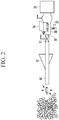
- FIG. 2 is a schematic diagram showing a structure of the apparatus for removing a bird nest of a blast furnace according to the present exemplary embodiment.
- FIGS. 1 and 2 disclose the apparatus for removing a bird nest of a blast furnace for effectively removing a bird nest 3 accumulated on a reactor core to activate a reactor core in a blast furnace 1.
- the apparatus for removing a bird nest of a blast furnace may include a pulverized coal lance 10 connected with a combustion zone 2 inside the blast furnace 1 to inject pulverized coal, a flux wired capsule 20 that is supplied to the bird nest 3 around the combustion zone 2 through the pulverized coal lance 10 to melt and remove the bird nest 3, and a high-pressure projectile 30 that is installed to be connected with an end portion of the pulverized coal lance 10 while accommodating the capsule 20 to shoot the capsule 20 to the bird nest 3 using high-pressure nitrogen gas.
- the capsule 20 may be shot to the bird nest 3 accumulated on the reactor core through the high-pressure projectile 30 using high-pressure nitrogen gas to remove the bird nest 3 via a reaction between the flux in the capsule 20 and the bird nest 3.
- the pulverized coal lance 10 put into the combustion zone 2 of the blast furnace 1 may further include a control valve 11 that is installed between the pulverized coal lance 10 and the high-pressure projectile 30 to control a supplied high-pressure nitrogen gas amount, and may further include a blow pipe 12 that is connectively installed outside the pulverized coal lance 10 to supply wind.
- Speed of injecting high-pressure nitrogen gas and the amount of the nitrogen gas may be controlled through the control valve 11 installed in the pulverized coal lance 10 to control shooting speed of the capsule 20 and may more effectively transmit wind to the pulverized coal lance 10 through the blow pipe 12 installed outside the pulverized coal lance 10.
- the high-pressure projectile 30 for shooting the capsule 20 to the bird nest 3 may further include a high-pressure gas container 31 that is connectively installed to a rear side of the high-pressure projectile 30 to accommodate and supply high-pressure nitrogen gas, and may further include a control valve 32 installed between the high-pressure projectile 30 and the high-pressure gas container 31 to control the amount of high-pressure nitrogen gas.
- the high-pressure projectile 30 may receive high-pressure nitrogen gas from the high-pressure gas container 31 installed at a rear side of the high-pressure projectile 30 to shoot the capsule 20, and may control the amount of gas supplied to the high-pressure projectile 30 from the high-pressure gas container 31 through the control valve 32.
- the high-pressure projectile 30 may include a loader 33 for loading and shooting the plurality of capsules 20, and a cover 34 installed in the loader 33 to be open and closed, and thus, the plurality of capsules 20 may be shot to the bird nest 3 of a reactor core in a state in which the capsules 20 are loaded in the loader 33 through a structure of the high-pressure projectile 30, and the cover 34 to be open and closed may be installed to maintain air-tightness of the loader 33.
- FIG. 3 is a schematic diagram showing a capsule of an apparatus for removing a bird nest according to the present exemplary embodiment.
- FIG. 4 is a schematic diagram showing a configuration of a capsule according to the present exemplary embodiment.
- the capsule 20 may be molded of a plastic material and may be configured to accommodate a mill scale flux containing water and a hydrogen peroxide solution or a hydrogen peroxide aqueous solution therein.
- a decomposition and exothermic reaction may proceed via a catalyst decomposition reaction with the bird nest 3 in the blast furnace 1 due to a material contained in the capsule 20, carbon in a pulverized powder may combust due to oxygen generated during decomposition, and the bird nest 3 may be removed by forming melt thereof to clean the bird nest 3.
- the capsule 20 may be configured to include a warhead 21 installed in a front portion thereof to be inserted into the bird nest 3, a cylinder 22 installed behind the warhead 21 to contain a flux therein, and a cap 23 installed behind the cylinder 22 to seal the cylinder 22.
- the warhead 21 and the cap 23 may include sealing grooves 21a and 23a formed on external circumferential surfaces thereof, respectively, and may be configured in such a way that sealing rings 21b and 23 are installed at the sealing grooves 21a and 23a, respectively, to seal the cylinder 22.
- the air-tightness of the cylinder 22 may be maintained through the warhead 21 and cap 23, and the sealing rings 21b and 23b coupled thereto to stably put materials contained in the cylinder 22 into the bird nest 3.
- the above configured capsule 20 may be shot into the bird nest 3 of the blast furnace 1 to remove the bird nest 3, and thus, the capsule 20 containing a mill scale flux along with a hydrogen peroxide solution may be continuously put into the bird nest 3 and may be mixed with pulverized powders of the bird nest 3 to remove the pulverized powders, and accordingly, a passage may be formed to allow gas to flow through the reactor core to overcome deactivation of the reactor core.
- FIG. 5 is a schematic diagram of a capsule according to another exemplary embodiment of the present exemplary embodiment.
- the cylinder 22 may be configured as a large capacity cylinder 22a connected with another cylinder, and the large capacity cylinder 22a may include a flexible connection portion 22b installed at an intermediate portion thereof to be bent during entrance into the bird nest 3.
- the capsule 20 may have an optimum length of 200 mm to be injected through the pulverized coal lance 10, but when the large capacity cylinder 22a formed by increasing the length of the capsule 20 is used to inject a larger amount of materials, a problem is predicted to arise in that the materials are not transmitted through the bent pulverized coal lance 10 and the pulverized coal lance 10 clogs, and thus, to prevent the problem, the flexible connection portion 22b may be connectively formed in the intermediate portion of the large capacity cylinder 22a to allow materials to smoothly pass through the bent portion.
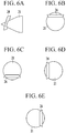
- FIG. 6 is a schematic diagram showing a state in which a position adjustment plate is installed in a capsule according to the present exemplary embodiment.
- the capsule 20 may further include a position adjustment plate 24 that is inserted into the warhead 21 to adjust a proceeding position of the capsule 20, and the position adjustment plate 24 may be selectively installed at up, down, left, and right sides of the warhead 21 to adjust a proceeding position of the warhead 21 through a load of the position adjustment plate 24 and to adjust a destination point of the capsule 20 in up, down, left, and right directions.
- gas in a furnace may act in a lower direction of the position adjustment plate 24 inserted into the warhead 21 while the capsule 20 proceeds, and thus, a position of the warhead 21 of the capsule 20 inserted into the bird nest 3 may be changed, thereby adjusting a destination of the capsule 20 in up, down, left, and right directions.
- the position of the position adjustment plate 24 inserted into the warhead 21 of the capsule 20 may be adjusted in up, down, left, and right directions to be moved to a target position of the bird nest 3, and then, the control valve 32 of the high-pressure projectile 30 may be open to put the capsule 20 into the bird nest 3 due to high-pressure nitrogen gas, and accordingly, a material for forming a mill scale flux contained in the capsule 20 may be uniformly distributed in up, down, left, and right direction rather than being concentrated and shot into one point.
- ventilation resistance may be reduced and hot air blown through a wind hole may be deeply injected into a reactor core, and thus, gas and the flux may smoothly flow, a wind flow rate may be increased, and a wind pressure may be reduced to activate the reactor core.
- the bird nest 3 of the reactor core of the blast furnace 1 may be effectively removed to prevent reduction in an output due to degradation in a wind amount generated due to deactivated reactor core and to lower a wind pressure by enhancing a state of the reactor core, and thus, since a furnace state may be stabilized and pulverized powders of the bird nest 3 may react with a flux to remove the pulverized powders, efficiency of transmitting hot air may be prevented from being lowered due to pulverized powders, thereby increasing an output.
Landscapes
- Engineering & Computer Science (AREA)
- General Engineering & Computer Science (AREA)
- Mechanical Engineering (AREA)
- Chemical & Material Sciences (AREA)
- Physics & Mathematics (AREA)
- Materials Engineering (AREA)
- Manufacturing & Machinery (AREA)
- Metallurgy (AREA)
- Organic Chemistry (AREA)
- Combustion & Propulsion (AREA)
- Fluid Mechanics (AREA)
- Thermal Sciences (AREA)
- Manufacture Of Iron (AREA)
- Waste-Gas Treatment And Other Accessory Devices For Furnaces (AREA)
Abstract
Description
- Disclosed is an apparatus for removing a bird nest that accumulates on a reactor core of a blast furnace.
- In general, an iron-making process of a blast furnace is a process of producing molten metal by charging iron ore as a raw material of the molten metal and cokes as fuel in a blast furnace and reducing and melting iron ore using high-temperature heat generated via combustion of the cokes and reduction gas.
- In a blast furnace operation for injecting pulverized coal, as cokes is replaced by pulverized coal, a ratio of an ore thickness to a cokes thickness is increased to reduce combustion of cokes at a furnace lower part, and resultantly, sinking speed of charged materials in a furnace is degraded and, accordingly, as a retention time of cokes in a blast furnace is increased, the possibility of collision between cokes particles in a combustion zone is further increased, and in this case, pulverized cokes generated by mechanical wear via a violent crash reaction accumulate on a cokes layer at a predetermined position in the furnace. That is, a bird nest that is a layer charged with cokes is formed on a reactor core of a blast furnace. The bird nest accumulates around a combustion zone of the blast furnace reactor core.
- Accordingly, to smoothly perform a blast furnace operation, reduction gas generated at a lower part of the blast furnace needs to be smoothly moved to an upper part of the blast furnace. To this end, a charged layer of cokes charged in the furnace needs to be in a sound state.
- The sound state of the layer charged with cokes in the furnace means that the amount of powders less than 3 mm is low between charged layers and, accordingly, means that, when the powders less than 3 mm are removed, an air void is appropriately ensured to smoothly facilitate flow of reduction gas and flow of melted material in a furnace, such as molten metal and slag.
- That is, a high-temperature and high-pressure counter flow reactor reduces sintered ore using CO gas that is a reducing agent obtained by combustion of cokes charged in a furnace with heat wind supplied from the lower part to produce molten metal. Gas formed in a combustion zone before a wind hole needs to be transmitted through a layer charged with cokes and to be uniformly spread in a radius direction and a vertical direction of the blast furnace, and to be prevented from channeling.
- However, a large amount of powders generally accumulate on a reactor core part, and thus, gas does not penetrate into the center of the blast furnace.
- As described above, to remove pulverized powders present in a zone of a layer with powers less than 3 mm, according to the prior art, the zone is blasted to remove the powders, but when such a method is used, there is a problem in that a large amount of powders are generated due to blasting. In addition, there is an attempt to inject ore or low melting point flux including oxygen through a wind hole to remove powders, but the possibility that injected materials act directly on the reactor core is low and, thus, air permeability/flowage are lowered to disadvantageously degrade a furnace state.
- An exemplary embodiment of the present invention provides an apparatus for removing a bird nest of a blast furnace having advantages of effectively removing a bird nest by injecting a flux wired capsule into a bird nest that accumulates on a reactor core of a blast furnace to improve a state of a reactor core.
- According to an embodiment of the present invention, an apparatus for removing a bird nest of a blast furnace includes a pulverized coal lance connected with a combustion zone inside the blast furnace to inject pulverized coal, a flux wired capsule supplied to the bird nest around the combustion zone through the pulverized coal lance to melt and remove the bird nest, and a high-pressure projectile installed to be connected with an end portion of the pulverized coal lance while accommodating the capsule to shoot the capsule to the bird nest using high-pressure nitrogen gas.
- The pulverized coal lance may further include a control valve installed between the pulverized coal lance and the high-pressure projectile to control a supplied high-pressure nitrogen gas amount.
- The pulverized coal lance may further include a blow pipe connectively installed outside the pulverized coal lance to supply wind.
- The high-pressure projectile may further include a high-pressure gas container for connectively installed to a rear side of the high-pressure projectile to accommodate and supply high-pressure nitrogen gas.
- The high-pressure projectile may further include a control value installed between the high-pressure projectile and the high-pressure gas container to control an amount of the high-pressure nitrogen gas.
- The high-pressure projectile may include a loader loading and shooting the plurality of capsules, and a cover installed in the loader to be open and closed.
- The capsule may be molded of a plastic material and may be configured to accommodate a mill scale flux containing water or a hydrogen peroxide solution or a hydrogen peroxide aqueous solution therein.
- The capsule may include a warhead installed in a front portion thereof to be inserted into the bird nest, a cylinder installed behind the warhead to contain a flux therein, and a cap installed behind the cylinder to seal the cylinder.
- The warhead and the cap may include sealing grooves formed on external circumferential surfaces thereof, respectively, and may be configured in such a way that sealing rings are installed at the sealing grooves, respectively, to seal the cylinder.
- The cylinder may be configured as a large capacity cylinder connected with another cylinder.
- The large capacity cylinder may include a flexible connection portion installed at an intermediate portion thereof to be bent during entrance into the bird nest.
- The capsule may further include a position adjustment plate inserted into the warhead to adjust a proceeding position of the capsule.
- The position adjustment plate may be selectively installed at up, down, left, and right sides of the warhead to adjust a proceeding position of the warhead through a load of the position adjustment plate and to adjust a destination point of the capsule in up, down, left, and right directions.
- According to the apparatus, a bird nest of a blast furnace reactor core may be effectively removed to prevent reduction in an output due to degradation in a wind amount generated due to deactivated reactor core and to lower a wind pressure and stabilize a furnace state by enhancing a state of the reactor core.
- In addition, since pulverized powders of the bird nest reacts with a flux to remove the pulverized powders, efficiency of transmitting hot air may not be prevented from being lowered due to pulverized powders, thereby increasing an output.
-
-
FIG. 1 is a schematic diagram showing an apparatus for removing a bird nest of a blast furnace according to an exemplary embodiment. -
FIG. 2 is a schematic diagram showing a structure of the apparatus for removing a bird nest of a blast furnace according to the present exemplary embodiment. -
FIG. 3 is a schematic diagram showing a capsule of an apparatus for removing a bird nest according to the present exemplary embodiment. -
FIG. 4 is a schematic diagram showing a configuration of a capsule according to the present exemplary embodiment. -
FIG. 5 is a schematic diagram of a capsule according to another exemplary embodiment of the present exemplary embodiment. -
FIG. 6 is a schematic diagram showing a state in which a position adjustment plate is installed in a capsule according to the present exemplary embodiment. - The technical terminology used herein is for the purpose of describing particular exemplary embodiments only and is not intended to be limiting of the present invention. Here, the singular expressions in the present specification include the plural expressions unless clearly specified otherwise in context. In the present specification, it should be understood that the terms, such as 'including' or 'having,' etc., are intended to indicate the existence of the features, regions, integers, steps, operations, components, and/or elements, and are not intended to preclude the possibility that other features, regions, integers, steps, operations, components, elements, and/or combinations thereof may exist or may be added.
- Exemplary embodiments of the present invention are described in detail so as for those of ordinary skill in the art to easily implement with reference to the accompanying drawing. It will be easily understood by those skilled in the art that various changes in form and details may be made therein without departing from the spirit and scope of the invention. Accordingly, as those skilled in the art would realize, the described embodiments may be modified in various different ways, all without departing from the spirit or scope of the present invention.
-
FIG. 1 is a schematic diagram showing an apparatus for removing a bird nest of a blast furnace according to an exemplary embodiment. -
FIG. 2 is a schematic diagram showing a structure of the apparatus for removing a bird nest of a blast furnace according to the present exemplary embodiment. -
FIGS. 1 and2 disclose the apparatus for removing a bird nest of a blast furnace for effectively removing abird nest 3 accumulated on a reactor core to activate a reactor core in ablast furnace 1. - The apparatus for removing a bird nest of a blast furnace according to the present exemplary embodiment may include a pulverized
coal lance 10 connected with acombustion zone 2 inside theblast furnace 1 to inject pulverized coal, a fluxwired capsule 20 that is supplied to thebird nest 3 around thecombustion zone 2 through the pulverizedcoal lance 10 to melt and remove thebird nest 3, and a high-pressure projectile 30 that is installed to be connected with an end portion of the pulverizedcoal lance 10 while accommodating thecapsule 20 to shoot thecapsule 20 to thebird nest 3 using high-pressure nitrogen gas. - That is, the
capsule 20 may be shot to thebird nest 3 accumulated on the reactor core through the high-pressure projectile 30 using high-pressure nitrogen gas to remove thebird nest 3 via a reaction between the flux in thecapsule 20 and thebird nest 3. - The pulverized
coal lance 10 put into thecombustion zone 2 of theblast furnace 1 may further include acontrol valve 11 that is installed between the pulverizedcoal lance 10 and the high-pressure projectile 30 to control a supplied high-pressure nitrogen gas amount, and may further include ablow pipe 12 that is connectively installed outside the pulverizedcoal lance 10 to supply wind. - Speed of injecting high-pressure nitrogen gas and the amount of the nitrogen gas may be controlled through the
control valve 11 installed in the pulverizedcoal lance 10 to control shooting speed of thecapsule 20 and may more effectively transmit wind to the pulverizedcoal lance 10 through theblow pipe 12 installed outside the pulverizedcoal lance 10. - The high-
pressure projectile 30 for shooting thecapsule 20 to thebird nest 3 may further include a high-pressure gas container 31 that is connectively installed to a rear side of the high-pressure projectile 30 to accommodate and supply high-pressure nitrogen gas, and may further include acontrol valve 32 installed between the high-pressure projectile 30 and the high-pressure gas container 31 to control the amount of high-pressure nitrogen gas. - The high-
pressure projectile 30 may receive high-pressure nitrogen gas from the high-pressure gas container 31 installed at a rear side of the high-pressure projectile 30 to shoot thecapsule 20, and may control the amount of gas supplied to the high-pressure projectile 30 from the high-pressure gas container 31 through thecontrol valve 32. - The high-
pressure projectile 30 may include aloader 33 for loading and shooting the plurality ofcapsules 20, and acover 34 installed in theloader 33 to be open and closed, and thus, the plurality ofcapsules 20 may be shot to thebird nest 3 of a reactor core in a state in which thecapsules 20 are loaded in theloader 33 through a structure of the high-pressure projectile 30, and thecover 34 to be open and closed may be installed to maintain air-tightness of theloader 33. -
FIG. 3 is a schematic diagram showing a capsule of an apparatus for removing a bird nest according to the present exemplary embodiment. -
FIG. 4 is a schematic diagram showing a configuration of a capsule according to the present exemplary embodiment. - As shown in
FIGS. 3 and 4 , thecapsule 20 may be molded of a plastic material and may be configured to accommodate a mill scale flux containing water and a hydrogen peroxide solution or a hydrogen peroxide aqueous solution therein. - That is, a decomposition and exothermic reaction may proceed via a catalyst decomposition reaction with the
bird nest 3 in theblast furnace 1 due to a material contained in thecapsule 20, carbon in a pulverized powder may combust due to oxygen generated during decomposition, and thebird nest 3 may be removed by forming melt thereof to clean thebird nest 3. - The
capsule 20 may be configured to include awarhead 21 installed in a front portion thereof to be inserted into thebird nest 3, acylinder 22 installed behind thewarhead 21 to contain a flux therein, and acap 23 installed behind thecylinder 22 to seal thecylinder 22. - The
warhead 21 and thecap 23 may include sealinggrooves rings sealing grooves cylinder 22. - The air-tightness of the
cylinder 22 may be maintained through thewarhead 21 andcap 23, and thesealing rings cylinder 22 into thebird nest 3. - Accordingly, the above configured
capsule 20 may be shot into thebird nest 3 of theblast furnace 1 to remove thebird nest 3, and thus, thecapsule 20 containing a mill scale flux along with a hydrogen peroxide solution may be continuously put into thebird nest 3 and may be mixed with pulverized powders of thebird nest 3 to remove the pulverized powders, and accordingly, a passage may be formed to allow gas to flow through the reactor core to overcome deactivation of the reactor core. -
FIG. 5 is a schematic diagram of a capsule according to another exemplary embodiment of the present exemplary embodiment. - As shown in
FIG. 5 , thecylinder 22 may be configured as alarge capacity cylinder 22a connected with another cylinder, and thelarge capacity cylinder 22a may include aflexible connection portion 22b installed at an intermediate portion thereof to be bent during entrance into thebird nest 3. - That is, the
capsule 20 may have an optimum length of 200 mm to be injected through the pulverizedcoal lance 10, but when thelarge capacity cylinder 22a formed by increasing the length of thecapsule 20 is used to inject a larger amount of materials, a problem is predicted to arise in that the materials are not transmitted through the bent pulverizedcoal lance 10 and the pulverizedcoal lance 10 clogs, and thus, to prevent the problem, theflexible connection portion 22b may be connectively formed in the intermediate portion of thelarge capacity cylinder 22a to allow materials to smoothly pass through the bent portion. -
FIG. 6 is a schematic diagram showing a state in which a position adjustment plate is installed in a capsule according to the present exemplary embodiment. - As shown in
FIG. 6 , thecapsule 20 may further include aposition adjustment plate 24 that is inserted into thewarhead 21 to adjust a proceeding position of thecapsule 20, and theposition adjustment plate 24 may be selectively installed at up, down, left, and right sides of thewarhead 21 to adjust a proceeding position of thewarhead 21 through a load of theposition adjustment plate 24 and to adjust a destination point of thecapsule 20 in up, down, left, and right directions. - That is, when a gap is formed in the warhead of the
capsule 20 and theposition adjustment plate 24 with a diameter equal to or less than thecapsule 20 is inserted into the gap, gas in a furnace may act in a lower direction of theposition adjustment plate 24 inserted into thewarhead 21 while thecapsule 20 proceeds, and thus, a position of thewarhead 21 of thecapsule 20 inserted into thebird nest 3 may be changed, thereby adjusting a destination of thecapsule 20 in up, down, left, and right directions. - Accordingly, after the
capsule 20 is positioned in the pulverizedcoal lance 10, the position of theposition adjustment plate 24 inserted into thewarhead 21 of thecapsule 20 may be adjusted in up, down, left, and right directions to be moved to a target position of thebird nest 3, and then, thecontrol valve 32 of the high-pressure projectile 30 may be open to put thecapsule 20 into thebird nest 3 due to high-pressure nitrogen gas, and accordingly, a material for forming a mill scale flux contained in thecapsule 20 may be uniformly distributed in up, down, left, and right direction rather than being concentrated and shot into one point. - Accordingly, when pulverized powders of the
bird nest 3 are removed by the flux contained in thecylinder 22 of thecapsule 20, ventilation resistance may be reduced and hot air blown through a wind hole may be deeply injected into a reactor core, and thus, gas and the flux may smoothly flow, a wind flow rate may be increased, and a wind pressure may be reduced to activate the reactor core. - Accordingly, the
bird nest 3 of the reactor core of theblast furnace 1 may be effectively removed to prevent reduction in an output due to degradation in a wind amount generated due to deactivated reactor core and to lower a wind pressure by enhancing a state of the reactor core, and thus, since a furnace state may be stabilized and pulverized powders of thebird nest 3 may react with a flux to remove the pulverized powders, efficiency of transmitting hot air may be prevented from being lowered due to pulverized powders, thereby increasing an output. - While this invention has been illustrated and described in connection with what is presently considered to be practical exemplary embodiments, it is to be understood that the invention is implemented in various different forms by those of ordinary skill in the art. The prevent invention is intended to cover various modifications and equivalent arrangements included within the spirit and scope of the appended claims.
Claims (13)
- An apparatus for removing a bird nest of a blast furnace, comprising:a pulverized coal lance connected with a combustion zone inside the blast furnace to inject pulverized coal;a flux wired capsule supplied to the bird nest around the combustion zone through the pulverized coal lance to melt and remove the bird nest; anda high-pressure projectile installed to be connected with an end portion of the pulverized coal lance while accommodating the capsule to shoot the capsule to the bird nest using high-pressure nitrogen gas.
- The apparatus of claim 1, wherein:
the pulverized coal lance further includes a control valve installed between the pulverized coal lance and the high-pressure projectile to control a supplied high-pressure nitrogen gas amount. - The apparatus of claim 2, wherein:
the pulverized coal lance further includes a blow pipe connectively installed outside the pulverized coal lance to supply wind. - The apparatus of claim 1, wherein:
the high-pressure projectile further includes a high-pressure gas container for connectively installed to a rear side of the high-pressure projectile to accommodate and supply high-pressure nitrogen gas. - The apparatus of claim 4, wherein:
the high-pressure projectile further includes a control value installed between the high-pressure projectile and the high-pressure gas container to control an amount of the high-pressure nitrogen gas supplied. - The apparatus of claim 1, wherein:
the high-pressure projectile includes a loader loading and shooting the plurality of capsules, and a cover installed in the loader to be open and closed. - The apparatus of claim 1, wherein:
the capsule is molded of a plastic material and is configured to accommodate a mill scale flux containing water or a hydrogen peroxide solution or a hydrogen peroxide aqueous solution therein. - The apparatus of claim 7, wherein:
the capsule includes a warhead installed in a front portion thereof to be inserted into the bird nest, a cylinder installed behind the warhead to contain a flux therein, and a cap installed behind the cylinder to seal the cylinder. - The apparatus of claim 8, wherein:
the warhead and the cap include sealing grooves formed on external circumferential surfaces thereof, respectively, and are configured in such a way that sealing rings are installed at the sealing grooves, respectively, to seal the cylinder. - The apparatus of claim 8, wherein:
the cylinder is configured as a large capacity cylinder connected with another cylinder. - The apparatus of claim 10, wherein:
the large capacity cylinder includes a flexible connection portion installed at an intermediate portion thereof to be bent during entrance into the bird nest. - The apparatus of claim 8, wherein:
the capsule further includes a position adjustment plate inserted into the warhead to adjust a proceeding position of the capsule. - The apparatus of claim 12, wherein:
the position adjustment plate is selectively installed at up, down, left, and right sides of the warhead to adjust a proceeding position of the warhead through a load of the position adjustment plate and to adjust a destination point of the capsule in up, down, left, and right directions.
Applications Claiming Priority (2)
| Application Number | Priority Date | Filing Date | Title |
|---|---|---|---|
| KR1020160102537A KR101759333B1 (en) | 2016-08-11 | 2016-08-11 | Apparatus for destroying bird's nest in blast furnace |
| PCT/KR2016/012250 WO2018030585A1 (en) | 2016-08-11 | 2016-10-28 | Apparatus for removing bird's nest in blast furnace |
Publications (2)
| Publication Number | Publication Date |
|---|---|
| EP3498868A1 true EP3498868A1 (en) | 2019-06-19 |
| EP3498868A4 EP3498868A4 (en) | 2019-07-17 |
Family
ID=59430841
Family Applications (1)
| Application Number | Title | Priority Date | Filing Date |
|---|---|---|---|
| EP16912783.4A Withdrawn EP3498868A4 (en) | 2016-08-11 | 2016-10-28 | Apparatus for removing bird's nest in blast furnace |
Country Status (5)
| Country | Link |
|---|---|
| EP (1) | EP3498868A4 (en) |
| JP (1) | JP6714768B2 (en) |
| KR (1) | KR101759333B1 (en) |
| CN (1) | CN109563557A (en) |
| WO (1) | WO2018030585A1 (en) |
Families Citing this family (2)
| Publication number | Priority date | Publication date | Assignee | Title |
|---|---|---|---|---|
| KR101850659B1 (en) * | 2017-03-17 | 2018-04-20 | 임정륜 | Apparatus for supplying recarburizer of electric furnace using tire powder and supplying method thereof |
| KR102083535B1 (en) * | 2017-12-22 | 2020-03-02 | 주식회사 포스코 | Operating method and apparatus for blast furnace |
Family Cites Families (11)
| Publication number | Priority date | Publication date | Assignee | Title |
|---|---|---|---|---|
| DE3149595A1 (en) * | 1981-12-15 | 1983-07-21 | Dynamit Nobel Ag, 5210 Troisdorf | Aerodynamic braking device for missiles, especially rockets |
| JPH0689382B2 (en) * | 1986-02-26 | 1994-11-09 | 株式会社神戸製鋼所 | Powder injection blast furnace operation method |
| JP3735184B2 (en) * | 1997-06-26 | 2006-01-18 | 新日本製鐵株式会社 | Blast furnace operation method |
| US6371030B1 (en) * | 1999-08-09 | 2002-04-16 | The United States Of America As Represented By The Secretary Of The Navy | Training projectile using shape memory alloy members |
| JP2004012104A (en) * | 2002-06-11 | 2004-01-15 | Nisshin Steel Co Ltd | Burner structure for blowing pulverized coal fuel into blast furnace |
| EP1793166B1 (en) * | 2005-12-03 | 2008-06-04 | HNE Technologie AG | Method for the inside cleaning of industrial furnaces, silos and such through bombardment with industrial guns |
| JP2007170794A (en) * | 2005-12-20 | 2007-07-05 | Satoshi Miyazaki | Bullet-shape shotgun pellet for firearm |
| KR20120036174A (en) * | 2010-10-07 | 2012-04-17 | 오미혜 | Composition of additive for steel furnace efficiency |
| KR101203651B1 (en) * | 2011-05-13 | 2012-11-27 | 주식회사 포스코 | Apparatus for destroying bird's nest in blast furnace |
| KR101267744B1 (en) * | 2011-06-29 | 2013-05-27 | 현대제철 주식회사 | apparatus for pulverized coal injection of blast furnace |
| KR101673174B1 (en) * | 2015-12-23 | 2016-11-07 | 주식회사 포스코 | Device and method for removal bird nest of raceway in blast furnace |
-
2016
- 2016-08-11 KR KR1020160102537A patent/KR101759333B1/en not_active Expired - Fee Related
- 2016-10-28 EP EP16912783.4A patent/EP3498868A4/en not_active Withdrawn
- 2016-10-28 JP JP2019506129A patent/JP6714768B2/en active Active
- 2016-10-28 CN CN201680088334.6A patent/CN109563557A/en active Pending
- 2016-10-28 WO PCT/KR2016/012250 patent/WO2018030585A1/en not_active Ceased
Also Published As
| Publication number | Publication date |
|---|---|
| EP3498868A4 (en) | 2019-07-17 |
| WO2018030585A1 (en) | 2018-02-15 |
| KR101759333B1 (en) | 2017-07-18 |
| CN109563557A (en) | 2019-04-02 |
| JP6714768B2 (en) | 2020-06-24 |
| JP2019523385A (en) | 2019-08-22 |
Similar Documents
| Publication | Publication Date | Title |
|---|---|---|
| EP2757163A1 (en) | Slag supply container for electric furnace for steel slag reduction | |
| KR101728286B1 (en) | Exhaust gas treatment method and exhaust gas treatment device | |
| KR102227326B1 (en) | Electric furnace | |
| KR20120085255A (en) | Molten metal producing device | |
| JPS62263906A (en) | Method for blowing pulverized coal from blast furnace tuyere | |
| GEP20166469B (en) | Method for melting steel with one aggregate and aggregate | |
| KR101759333B1 (en) | Apparatus for destroying bird's nest in blast furnace | |
| CN102047059B (en) | Gas cupola for melting metal | |
| EP2699862B1 (en) | Device to inject solid material into a bath of liquid metal, and corresponding method | |
| EP3492852A1 (en) | Sintering apparatus and method for manufacturing sintered ore using same | |
| JP2011214022A (en) | Method for operating blast furnace | |
| CN107249785A (en) | The method for sealing and repairing fire resisting tap | |
| KR20240016794A (en) | Electric furnace | |
| JP4747662B2 (en) | Lance for blowing gas reducing material, blast furnace and blast furnace operating method | |
| KR102083535B1 (en) | Operating method and apparatus for blast furnace | |
| EP2586877B1 (en) | Furnace having even distribution of gas | |
| KR101655213B1 (en) | Device for activiting furnace center in blasst furnace, and thr method | |
| KR101673174B1 (en) | Device and method for removal bird nest of raceway in blast furnace | |
| KR101511720B1 (en) | Manufacturing apparatus for molten metal and method thereof | |
| JP2019127615A (en) | Method of charging raw materials into blast furnace | |
| JP2015178660A (en) | Raw material charging method for blast furnace | |
| KR101191969B1 (en) | Control device and control method for reduction gas of pig iron manufacturing equipment | |
| KR100431871B1 (en) | Operation method for solving immunity of reactor core in the furnace operation with a large quantity of pulverized coal | |
| KR20200057498A (en) | Manufacturing method for molten iron and apparatus thereof | |
| JPS6380190A (en) | Vertical type furnace for smelting |
Legal Events
| Date | Code | Title | Description |
|---|---|---|---|
| PUAI | Public reference made under article 153(3) epc to a published international application that has entered the european phase |
Free format text: ORIGINAL CODE: 0009012 |
|
| 17P | Request for examination filed |
Effective date: 20190205 |
|
| AK | Designated contracting states |
Kind code of ref document: A1 Designated state(s): AL AT BE BG CH CY CZ DE DK EE ES FI FR GB GR HR HU IE IS IT LI LT LU LV MC MK MT NL NO PL PT RO RS SE SI SK SM TR |
|
| AX | Request for extension of the european patent |
Extension state: BA ME |
|
| A4 | Supplementary search report drawn up and despatched |
Effective date: 20190619 |
|
| RIC1 | Information provided on ipc code assigned before grant |
Ipc: F42B 10/60 20060101ALI20190613BHEP Ipc: F41B 11/87 20130101ALI20190613BHEP Ipc: F27B 1/16 20060101ALI20190613BHEP Ipc: F42B 5/02 20060101ALI20190613BHEP Ipc: F42B 12/76 20060101ALI20190613BHEP Ipc: F27D 25/00 20100101ALI20190613BHEP Ipc: C21B 7/16 20060101AFI20190613BHEP Ipc: F42B 6/10 20060101ALI20190613BHEP Ipc: F42B 12/66 20060101ALI20190613BHEP Ipc: F27D 3/16 20060101ALI20190613BHEP Ipc: F42B 12/36 20060101ALI20190613BHEP Ipc: F42B 10/50 20060101ALI20190613BHEP Ipc: F27D 3/00 20060101ALI20190613BHEP |
|
| DAV | Request for validation of the european patent (deleted) | ||
| DAX | Request for extension of the european patent (deleted) | ||
| 17Q | First examination report despatched |
Effective date: 20200506 |
|
| STAA | Information on the status of an ep patent application or granted ep patent |
Free format text: STATUS: THE APPLICATION IS DEEMED TO BE WITHDRAWN |
|
| 18D | Application deemed to be withdrawn |
Effective date: 20200917 |