EP3498660B1 - System for regulating a vapour recovery pump - Google Patents
System for regulating a vapour recovery pump Download PDFInfo
- Publication number
- EP3498660B1 EP3498660B1 EP17207782.8A EP17207782A EP3498660B1 EP 3498660 B1 EP3498660 B1 EP 3498660B1 EP 17207782 A EP17207782 A EP 17207782A EP 3498660 B1 EP3498660 B1 EP 3498660B1
- Authority
- EP
- European Patent Office
- Prior art keywords
- signal
- current consumption
- vapour
- solenoid coil
- fuel dispensing
- Prior art date
- Legal status (The legal status is an assumption and is not a legal conclusion. Google has not performed a legal analysis and makes no representation as to the accuracy of the status listed.)
- Active
Links
Images


Classifications
-
- F—MECHANICAL ENGINEERING; LIGHTING; HEATING; WEAPONS; BLASTING
- F04—POSITIVE - DISPLACEMENT MACHINES FOR LIQUIDS; PUMPS FOR LIQUIDS OR ELASTIC FLUIDS
- F04B—POSITIVE-DISPLACEMENT MACHINES FOR LIQUIDS; PUMPS
- F04B49/00—Control, e.g. of pump delivery, or pump pressure of, or safety measures for, machines, pumps, or pumping installations, not otherwise provided for, or of interest apart from, groups F04B1/00 - F04B47/00
- F04B49/06—Control using electricity
-
- B—PERFORMING OPERATIONS; TRANSPORTING
- B67—OPENING, CLOSING OR CLEANING BOTTLES, JARS OR SIMILAR CONTAINERS; LIQUID HANDLING
- B67D—DISPENSING, DELIVERING OR TRANSFERRING LIQUIDS, NOT OTHERWISE PROVIDED FOR
- B67D7/00—Apparatus or devices for transferring liquids from bulk storage containers or reservoirs into vehicles or into portable containers, e.g. for retail sale purposes
- B67D7/04—Apparatus or devices for transferring liquids from bulk storage containers or reservoirs into vehicles or into portable containers, e.g. for retail sale purposes for transferring fuels, lubricants or mixed fuels and lubricants
- B67D7/0476—Vapour recovery systems
-
- B—PERFORMING OPERATIONS; TRANSPORTING
- B67—OPENING, CLOSING OR CLEANING BOTTLES, JARS OR SIMILAR CONTAINERS; LIQUID HANDLING
- B67D—DISPENSING, DELIVERING OR TRANSFERRING LIQUIDS, NOT OTHERWISE PROVIDED FOR
- B67D7/00—Apparatus or devices for transferring liquids from bulk storage containers or reservoirs into vehicles or into portable containers, e.g. for retail sale purposes
- B67D7/04—Apparatus or devices for transferring liquids from bulk storage containers or reservoirs into vehicles or into portable containers, e.g. for retail sale purposes for transferring fuels, lubricants or mixed fuels and lubricants
- B67D7/0476—Vapour recovery systems
- B67D7/0478—Vapour recovery systems constructional features or components
- B67D7/048—Vapour flow control means, e.g. valves, pumps
- B67D7/0482—Vapour flow control means, e.g. valves, pumps using pumps driven at different flow rates
- B67D7/0486—Pumps driven in response to electric signals indicative of pressure, temperature or liquid flow
-
- F—MECHANICAL ENGINEERING; LIGHTING; HEATING; WEAPONS; BLASTING
- F04—POSITIVE - DISPLACEMENT MACHINES FOR LIQUIDS; PUMPS FOR LIQUIDS OR ELASTIC FLUIDS
- F04B—POSITIVE-DISPLACEMENT MACHINES FOR LIQUIDS; PUMPS
- F04B17/00—Pumps characterised by combination with, or adaptation to, specific driving engines or motors
- F04B17/03—Pumps characterised by combination with, or adaptation to, specific driving engines or motors driven by electric motors
- F04B17/04—Pumps characterised by combination with, or adaptation to, specific driving engines or motors driven by electric motors using solenoids
-
- F—MECHANICAL ENGINEERING; LIGHTING; HEATING; WEAPONS; BLASTING
- F04—POSITIVE - DISPLACEMENT MACHINES FOR LIQUIDS; PUMPS FOR LIQUIDS OR ELASTIC FLUIDS
- F04B—POSITIVE-DISPLACEMENT MACHINES FOR LIQUIDS; PUMPS
- F04B17/00—Pumps characterised by combination with, or adaptation to, specific driving engines or motors
- F04B17/03—Pumps characterised by combination with, or adaptation to, specific driving engines or motors driven by electric motors
- F04B17/04—Pumps characterised by combination with, or adaptation to, specific driving engines or motors driven by electric motors using solenoids
- F04B17/042—Pumps characterised by combination with, or adaptation to, specific driving engines or motors driven by electric motors using solenoids the solenoid motor being separated from the fluid flow
- F04B17/044—Pumps characterised by combination with, or adaptation to, specific driving engines or motors driven by electric motors using solenoids the solenoid motor being separated from the fluid flow using solenoids directly actuating the piston
-
- F—MECHANICAL ENGINEERING; LIGHTING; HEATING; WEAPONS; BLASTING
- F04—POSITIVE - DISPLACEMENT MACHINES FOR LIQUIDS; PUMPS FOR LIQUIDS OR ELASTIC FLUIDS
- F04B—POSITIVE-DISPLACEMENT MACHINES FOR LIQUIDS; PUMPS
- F04B35/00—Piston pumps specially adapted for elastic fluids and characterised by the driving means to their working members, or by combination with, or adaptation to, specific driving engines or motors, not otherwise provided for
- F04B35/04—Piston pumps specially adapted for elastic fluids and characterised by the driving means to their working members, or by combination with, or adaptation to, specific driving engines or motors, not otherwise provided for the means being electric
- F04B35/045—Piston pumps specially adapted for elastic fluids and characterised by the driving means to their working members, or by combination with, or adaptation to, specific driving engines or motors, not otherwise provided for the means being electric using solenoids
-
- F—MECHANICAL ENGINEERING; LIGHTING; HEATING; WEAPONS; BLASTING
- F04—POSITIVE - DISPLACEMENT MACHINES FOR LIQUIDS; PUMPS FOR LIQUIDS OR ELASTIC FLUIDS
- F04B—POSITIVE-DISPLACEMENT MACHINES FOR LIQUIDS; PUMPS
- F04B49/00—Control, e.g. of pump delivery, or pump pressure of, or safety measures for, machines, pumps, or pumping installations, not otherwise provided for, or of interest apart from, groups F04B1/00 - F04B47/00
- F04B49/06—Control using electricity
- F04B49/065—Control using electricity and making use of computers
-
- H—ELECTRICITY
- H02—GENERATION; CONVERSION OR DISTRIBUTION OF ELECTRIC POWER
- H02P—CONTROL OR REGULATION OF ELECTRIC MOTORS, ELECTRIC GENERATORS OR DYNAMO-ELECTRIC CONVERTERS; CONTROLLING TRANSFORMERS, REACTORS OR CHOKE COILS
- H02P25/00—Arrangements or methods for the control of AC motors characterised by the kind of AC motor or by structural details
- H02P25/02—Arrangements or methods for the control of AC motors characterised by the kind of AC motor or by structural details characterised by the kind of motor
- H02P25/032—Reciprocating, oscillating or vibrating motors
-
- F—MECHANICAL ENGINEERING; LIGHTING; HEATING; WEAPONS; BLASTING
- F02—COMBUSTION ENGINES; HOT-GAS OR COMBUSTION-PRODUCT ENGINE PLANTS
- F02D—CONTROLLING COMBUSTION ENGINES
- F02D41/00—Electrical control of supply of combustible mixture or its constituents
- F02D41/20—Output circuits, e.g. for controlling currents in command coils
- F02D2041/202—Output circuits, e.g. for controlling currents in command coils characterised by the control of the circuit
- F02D2041/2058—Output circuits, e.g. for controlling currents in command coils characterised by the control of the circuit using information of the actual current value
-
- F—MECHANICAL ENGINEERING; LIGHTING; HEATING; WEAPONS; BLASTING
- F04—POSITIVE - DISPLACEMENT MACHINES FOR LIQUIDS; PUMPS FOR LIQUIDS OR ELASTIC FLUIDS
- F04B—POSITIVE-DISPLACEMENT MACHINES FOR LIQUIDS; PUMPS
- F04B2203/00—Motor parameters
- F04B2203/04—Motor parameters of linear electric motors
- F04B2203/0401—Current
-
- F—MECHANICAL ENGINEERING; LIGHTING; HEATING; WEAPONS; BLASTING
- F04—POSITIVE - DISPLACEMENT MACHINES FOR LIQUIDS; PUMPS FOR LIQUIDS OR ELASTIC FLUIDS
- F04B—POSITIVE-DISPLACEMENT MACHINES FOR LIQUIDS; PUMPS
- F04B2203/00—Motor parameters
- F04B2203/04—Motor parameters of linear electric motors
- F04B2203/0402—Voltage
Definitions
- the invention relates to a method for controlling a linear pump of a vapour recovery system in a fuel dispensing unit.
- the invention also relates to a vapour recovery system for recovering vapour from a motor vehicle tank via a fuel dispensing nozzle to a vapour tank.
- vapour recovery system When filling the tank of a motor vehicle, it is a common measure to recover the vapour escaping the tank when filling it with liquid fuel from a fuel pump unit.
- the vapour recovery is performed by a system which is incorporated in the fuel pump unit, such that vapour of hydrocarbons are prevented from escaping to the environment outside the tank of the motor vehicle.
- Such vapour recovery system typically consists of a vapour inlet arranged in a fuel dispensing nozzle, a vapour pump and a flow meter. The recovered vapour is accumulated in a vapour tank.
- the vapour pump draws fuel vapour from the tank of the motor vehicle, through the flow meter and to the vapour tank.
- the flow meter measures the vapour flow and compares the measured value with the flow of dispensed fuel.
- Adjusting means are connected to the flow meter and to the vapour pump so that the vapour flow matches the flow of the dispensed fuel.
- vapour recovery system Since a vapour recovery system consists of several components, there are several possible causes for such vapour recovery system to malfunction. If the value measured by the flow meter drops, this might be due to e.g. pump failure, flow meter failure, or dust, particles or other obstruction in the vapour line. Thus, there is a need for checking the correct operation of a vapour recovery system.
- EP1936188 discloses a known linear vapour recovery pump.
- WO2012089246 discloses a linear vapour recovery pump according to the preamble of appended claim 10.
- GB 2352437 discloses a method for control of a vapour recovery system.
- the vapour delivery rate is constantly detected.
- the value of the vapour delivery rate thus detected is transmitted to comparison means which compare it with a value of the liquid delivery rate and if the result of this comparison is outside a predetermined range, which may or may not be adjustable, an alarm is triggered in order to indicate a malfunction.
- vapour recovery systems are sensitive in terms of controlling the flow rate, e.g. due to temperature changes, clogging of nozzles and liquid flushes that temporarily impact the capacity of system.
- a method for controlling a linear pump of a vapour recovery system in a fuel dispensing unit is achieved, in full or at least in part, by a method for controlling a linear pump of a vapour recovery system in a fuel dispensing unit.
- the linear pump is flow controlled by a signal.
- the method comprises applying a known voltage to a solenoid coil of the linear pump for a predetermined time period, measuring a current consumption of the solenoid coil during the predetermined time period, and adjusting the signal based on the measured current consumption.
- a known voltage, switched or fixed, is applied over the coil to measure the current consumption and adjust the signal based on the same.
- the method may further comprise calculating a resistance of the solenoid coil based on the current consumption, and converting the calculated resistance into a temperature based on which the signal is adjusted.
- the resistance is dependent on heat build-up, ambient and pumped media temperature, the value can then be converted to a temperature.
- the calibrated power width modulation curve may thereafter be offset depending on the measured temperature.
- Each pump has a known resistance at 20° which is labelled on the pump that can be used in order to handle variations on different coils.
- the signal may be adjusted per an algorithm in a control unit based on the measured current consumption or the calculated resistance or temperature.
- the predetermined time period may be based on a duration of at least one cycle of a current consumption curve obtained from the signal.
- the steps of the method are conducted before a refueling may be started in the fuel dispensing unit.
- the steps of the method may be conducted during operation of the fuel dispensing unit. This way, it will be possible to also compensate for the self-heating of the fuel dispensing unit during operation.
- the current consumption of the solenoid coil is at first measured when the fuel dispensing unit is in an idle state and thereafter during operation. By comparing the calculated resistance based on the current consumption from these measurements the temperature due to self-heating of the fuel dispensing unit during operation may be determined and considered when adjusting the signal.
- several measurements may be conducted during the operation of the fuel dispensing unit such that the signal can be continuously adjusted.
- the step of adjusting the signal may be further based on a pressure drop due to the operation of the fuel dispensing unit.
- the pressure drop may be measured in real time and or be continuously monitored by the control unit. Another alternative is to monitor which nozzle is presently being used for the refueling operation(s) and thereafter read off a pressure drop value from a table based on the model of the fuel dispensing unit.
- the method may further comprise continuously monitoring the geometry of a current consumption curve obtained from the signal during operation of the fuel dispensing unit, and comparing the geometry of the obtained current consumption curve with the geometry of a current consumption curve obtained from the signal during calibration of the fuel dispensing unit.
- the signal may be a power width modulation signal.
- a vapour recovery system for recovering vapour from a motor vehicle tank via a fuel dispensing nozzle to a vapour tank.
- the vapour recovery system comprises a linear pump configured to pump vapour from the motor vehicle tank to the vapour tank, the linear pump being flow controlled by a signal applied to a solenoid coil, and a control unit configured to adjust the signal based on a measured current consumption of the solenoid coil.
- the control unit may further be configured to apply a known voltage to a solenoid coil of the linear pump for a predetermined time period, and measure the current consumption of the solenoid coil during the predetermined time period.
- the control unit may further be configured to calculate a resistance of the solenoid coil based on the current consumption, and to convert the calculated resistance into a temperature based on which the signal is adjusted.
- the signal may be a power width modulation signal.
- Fig. 1 illustrates a fuel dispensing unit 1 having hose storage spaces 2 on each opposing side, an electrical cabinet 3 containing all the electronics for the fuel dispensing unit 1, a hydraulic cabinet 4 containing fuel dispensing means (not shown), e.g. fuel metering means, valves, vapour recovery system etc., and a column 5 extending vertically between and separating the electrical cabinet 3 and the hydraulic cabinet 4 from the hose storage spaces.
- fuel dispensing means e.g. fuel metering means, valves, vapour recovery system etc.
- the fuel dispensing unit 1 is connected to an underground reservoir (not shown) containing fuel.
- an underground reservoir (not shown) containing fuel.
- the fuel is pumped from the underground reservoir by means of a pump which is located in the hydraulic cabinet 4, and from there to the column 5 and out to a nozzle 7 via a hose 6.
- the fuel dispensing unit 1 has a nozzle boot 8 for each nozzle 7, which nozzle boot 8 preferably comprises a sensor (not shown) for detecting if the nozzle 7 is present in the nozzle boot 8. Further, the nozzle 7 is equipped with a flow meter (not shown) for detecting the fuel flow rate from the nozzle 7 upon refuelling.
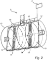
- FIG. 2 an exemplary embodiment of the vapour recovery system is illustrated.
- the vapour recovery system is used to recover vapour from the motor vehicle tank via the nozzle 7 to a vapour tank (not shown).
- the vapour recovery system comprises a linear pump 9 which is flow controlled by a signal applied to a solenoid coil 10 and which is configured to pump vapour from the motor vehicle tank to the vapour tank.
- the signal is a power width modulation signal.
- the vapour recovery system further comprises a control unit 11 which is configured to adjust the signal based on a measured current consumption of the solenoid coil 10. More specifically, in this exemplary embodiment, the control unit 11 is configured to adjust the power width modulation signal based on a resistance of the solenoid coil 10.
- the resistance of the solenoid coil 10 is calculated by applying a known voltage to the solenoid coil 10 for a predetermined time period, measuring a current consumption of the solenoid coil 10 during the predetermined time period, and calculating a resistance of the solenoid coil 10 based on the current consumption.
- the linear pump 9 has a pump housing 12 comprising a first chamber 13, a second chamber 14 and a third chamber 15.
- the first and second chambers 13, 14 are separated by a first piston 16 and the second and third chambers 14, 15 are separated by a second piston 17.
- the first and second pistons 16, 17 are movable in a horizontal direction of the pump housing 12 in order to repeatedly decrease and increase the volumes of the chambers 13, 14, 15 during use of the vapour recovery pump 9.
- the first and second pistons 16, 17 move reciprocally and substantially out of phase in relation to each other within the pump housing 12.
- the volume of each chamber 13, 14, 15 depends on the location of the pistons 16, 17, but the total volume of the chambers 13, 14, 15 is constant.
- the volumes of the first and third chambers 13, 15 are, however, always substantially equal in relation to each other.
- each one of the first and second pistons 16, 17 comprises a magnetic device 18.
- the control unit 11 includes electromagnetic control means which is provided to move the pistons 16, 17 by altering a magnetic field.
- Fig. 3 illustrates an exemplary embodiment of a method for controlling the linear pump 9 of the vapour recovery system.
- the method comprises applying S1 a known voltage to the solenoid coil 10 of the linear pump 9 for a predetermined time period, measuring S2 a current consumption of the solenoid coil during the predetermined time period, and adjusting S3 the signal based on the measured current consumption.
Landscapes
- Engineering & Computer Science (AREA)
- Mechanical Engineering (AREA)
- General Engineering & Computer Science (AREA)
- Physics & Mathematics (AREA)
- Fluid Mechanics (AREA)
- Power Engineering (AREA)
- Computer Hardware Design (AREA)
- Control Of Positive-Displacement Pumps (AREA)
- Loading And Unloading Of Fuel Tanks Or Ships (AREA)
- Supplying Secondary Fuel Or The Like To Fuel, Air Or Fuel-Air Mixtures (AREA)
Description
- The invention relates to a method for controlling a linear pump of a vapour recovery system in a fuel dispensing unit. The invention also relates to a vapour recovery system for recovering vapour from a motor vehicle tank via a fuel dispensing nozzle to a vapour tank.
- When filling the tank of a motor vehicle, it is a common measure to recover the vapour escaping the tank when filling it with liquid fuel from a fuel pump unit. The vapour recovery is performed by a system which is incorporated in the fuel pump unit, such that vapour of hydrocarbons are prevented from escaping to the environment outside the tank of the motor vehicle. Such vapour recovery system typically consists of a vapour inlet arranged in a fuel dispensing nozzle, a vapour pump and a flow meter. The recovered vapour is accumulated in a vapour tank.
- The vapour pump draws fuel vapour from the tank of the motor vehicle, through the flow meter and to the vapour tank. The flow meter measures the vapour flow and compares the measured value with the flow of dispensed fuel. Adjusting means are connected to the flow meter and to the vapour pump so that the vapour flow matches the flow of the dispensed fuel.
- Since a vapour recovery system consists of several components, there are several possible causes for such vapour recovery system to malfunction. If the value measured by the flow meter drops, this might be due to e.g. pump failure, flow meter failure, or dust, particles or other obstruction in the vapour line. Thus, there is a need for checking the correct operation of a vapour recovery system.
-
EP1936188 discloses a known linear vapour recovery pump.WO2012089246 discloses a linear vapour recovery pump according to the preamble of appendedclaim 10. -
GB 2352437 - A problem associated with the existing prior art is that the vapour recovery systems are sensitive in terms of controlling the flow rate, e.g. due to temperature changes, clogging of nozzles and liquid flushes that temporarily impact the capacity of system.
- It is an objective of the present invention to provide an improvement of the above technique and prior art. More particularly, it is an objective of this invention to provide an improved method for controlling a linear pump of a vapour recovery system in a fuel dispensing unit.
- According to a first aspect, these and other objects, and/or advantages that will be apparent from the following description of embodiments, are achieved, in full or at least in part, by a method for controlling a linear pump of a vapour recovery system in a fuel dispensing unit. The linear pump is flow controlled by a signal. The method comprises applying a known voltage to a solenoid coil of the linear pump for a predetermined time period, measuring a current consumption of the solenoid coil during the predetermined time period, and adjusting the signal based on the measured current consumption.
- In other words, during nozzle lift or even during the operation of the fuel dispensing unit, a known voltage, switched or fixed, is applied over the coil to measure the current consumption and adjust the signal based on the same.
- This is especially advantageous in that a much more exact control of the vapour recovery system can be established. In turn, this will reduce risk of shutting down systems because of temperature inconstancy. Furthermore, it is also possible to measure during one sinus wave at the start of the operation of the fuel dispensing unit and then measure again later during the operation of the fuel dispensing unit to determine if the system is affected during the refueling itself. This could be done by measuring the current but the form of the sinus wave is also affected.
- The method may further comprise calculating a resistance of the solenoid coil based on the current consumption, and converting the calculated resistance into a temperature based on which the signal is adjusted.
- As the resistance is dependent on heat build-up, ambient and pumped media temperature, the value can then be converted to a temperature.
- The calibrated power width modulation curve may thereafter be offset depending on the measured temperature. Each pump has a known resistance at 20° which is labelled on the pump that can be used in order to handle variations on different coils.
- The signal may be adjusted per an algorithm in a control unit based on the measured current consumption or the calculated resistance or temperature.
- The predetermined time period may be based on a duration of at least one cycle of a current consumption curve obtained from the signal.
- The steps of the method are conducted before a refueling may be started in the fuel dispensing unit.
- The steps of the method may be conducted during operation of the fuel dispensing unit. This way, it will be possible to also compensate for the self-heating of the fuel dispensing unit during operation. Preferably, the current consumption of the solenoid coil is at first measured when the fuel dispensing unit is in an idle state and thereafter during operation. By comparing the calculated resistance based on the current consumption from these measurements the temperature due to self-heating of the fuel dispensing unit during operation may be determined and considered when adjusting the signal. Naturally, several measurements may be conducted during the operation of the fuel dispensing unit such that the signal can be continuously adjusted.
- The step of adjusting the signal may be further based on a pressure drop due to the operation of the fuel dispensing unit. The pressure drop may be measured in real time and or be continuously monitored by the control unit. Another alternative is to monitor which nozzle is presently being used for the refueling operation(s) and thereafter read off a pressure drop value from a table based on the model of the fuel dispensing unit.
- The method may further comprise continuously monitoring the geometry of a current consumption curve obtained from the signal during operation of the fuel dispensing unit, and comparing the geometry of the obtained current consumption curve with the geometry of a current consumption curve obtained from the signal during calibration of the fuel dispensing unit.
- By learning the geometry of the current consumption curve when the fuel dispensing unit functions in a satisfactory manner it is possible to discover any type of failure in the fuel dispensing unit during operation by monitoring the geometry of the current consumption curve over time.
- The signal may be a power width modulation signal.
- According to a second aspect, these and other objects are achieved, in full or at least in part, by a vapour recovery system for recovering vapour from a motor vehicle tank via a fuel dispensing nozzle to a vapour tank. The vapour recovery system comprises a linear pump configured to pump vapour from the motor vehicle tank to the vapour tank, the linear pump being flow controlled by a signal applied to a solenoid coil, and a control unit configured to adjust the signal based on a measured current consumption of the solenoid coil.
- The control unit may further be configured to apply a known voltage to a solenoid coil of the linear pump for a predetermined time period, and measure the current consumption of the solenoid coil during the predetermined time period.
- The control unit may further be configured to calculate a resistance of the solenoid coil based on the current consumption, and to convert the calculated resistance into a temperature based on which the signal is adjusted.
- The signal may be a power width modulation signal.
- Effects and features of the second and third aspect of the present invention are largely analogous to those described above in connection with the first aspect of the inventive concept. Embodiments mentioned in relation to the first aspect of the present invention are largely compatible with the further aspects of the invention.
- Other objectives, features and advantages of the present invention will appear from the following detailed disclosure, from the attached claims, as well as from the drawings. It is noted that the invention relates to all possible combinations of features.
- Generally, all terms used in the claims are to be interpreted according to their ordinary meaning in the technical field, unless explicitly defined otherwise herein. All references to "a/an/the [element, device, component, means, step, etc.]" are to be interpreted openly as referring to at least one instance of said element, device, component, means, step, etc., unless explicitly stated otherwise.
- As used herein, the term "comprising" and variations of that term are not intended to exclude other additives, components, integers or steps.
- The above, as well as additional objects, features and advantages of the present invention, will be better understood through the following illustrative and non-limiting detailed description of embodiments of the present invention, with reference to the appended drawings, where the same reference numerals may be used for similar elements, and wherein:
-
Fig. 1 is a schematic view of an exemplary embodiment of a fuel dispensing unit comprising a vapour recovery system according to a second aspect of the invention. -
Fig. 2 is a perspective view of the vapour recovery system according to the second aspect of the invention. -
Fig. 3 is a flow chart of a method for controlling a linear pump of a vapour recovery system according to a first aspect of the invention. -
Fig. 1 illustrates afuel dispensing unit 1 havinghose storage spaces 2 on each opposing side, anelectrical cabinet 3 containing all the electronics for thefuel dispensing unit 1, a hydraulic cabinet 4 containing fuel dispensing means (not shown), e.g. fuel metering means, valves, vapour recovery system etc., and a column 5 extending vertically between and separating theelectrical cabinet 3 and the hydraulic cabinet 4 from the hose storage spaces. - The
fuel dispensing unit 1 is connected to an underground reservoir (not shown) containing fuel. When filling up the tank of a motor vehicle, the fuel is pumped from the underground reservoir by means of a pump which is located in the hydraulic cabinet 4, and from there to the column 5 and out to a nozzle 7 via a hose 6. - The
fuel dispensing unit 1 has anozzle boot 8 for each nozzle 7, whichnozzle boot 8 preferably comprises a sensor (not shown) for detecting if the nozzle 7 is present in thenozzle boot 8. Further, the nozzle 7 is equipped with a flow meter (not shown) for detecting the fuel flow rate from the nozzle 7 upon refuelling. - In
Fig. 2 , an exemplary embodiment of the vapour recovery system is illustrated. The vapour recovery system is used to recover vapour from the motor vehicle tank via the nozzle 7 to a vapour tank (not shown). The vapour recovery system comprises a linear pump 9 which is flow controlled by a signal applied to asolenoid coil 10 and which is configured to pump vapour from the motor vehicle tank to the vapour tank. In this specific embodiment, the signal is a power width modulation signal. - The vapour recovery system further comprises a
control unit 11 which is configured to adjust the signal based on a measured current consumption of thesolenoid coil 10. More specifically, in this exemplary embodiment, thecontrol unit 11 is configured to adjust the power width modulation signal based on a resistance of thesolenoid coil 10. The resistance of thesolenoid coil 10 is calculated by applying a known voltage to thesolenoid coil 10 for a predetermined time period, measuring a current consumption of thesolenoid coil 10 during the predetermined time period, and calculating a resistance of thesolenoid coil 10 based on the current consumption. - The linear pump 9 has a
pump housing 12 comprising afirst chamber 13, asecond chamber 14 and athird chamber 15. The first andsecond chambers first piston 16 and the second andthird chambers second piston 17. The first andsecond pistons pump housing 12 in order to repeatedly decrease and increase the volumes of thechambers second pistons pump housing 12. The volume of eachchamber pistons chambers third chambers second pistons magnetic device 18. Thecontrol unit 11 includes electromagnetic control means which is provided to move thepistons -
Fig. 3 illustrates an exemplary embodiment of a method for controlling the linear pump 9 of the vapour recovery system. The method comprises applying S1 a known voltage to thesolenoid coil 10 of the linear pump 9 for a predetermined time period, measuring S2 a current consumption of the solenoid coil during the predetermined time period, and adjusting S3 the signal based on the measured current consumption. - The skilled person realizes that a number of modifications of the embodiments described herein are possible without departing from the scope of the invention, which is defined in the appended claims.
Claims (13)
- A method for controlling a linear pump (9) of a vapour recovery system in a fuel dispensing unit (1), the linear pump (9) being flow controlled by a signal, wherein the method is characterized by:applying (S1) a known voltage to a solenoid coil (10) of the linear pump (9) for a predetermined time period,measuring (S2) a current consumption of the solenoid coil (10) during the predetermined time period, andadjusting (S3) the signal based on the measured current consumption.
- The method according to claim 1, further comprising calculating a resistance of the solenoid coil (10) based on the current consumption, and converting the calculated resistance into a temperature based on which the signal is adjusted.
- The method according to claim 1 or 2, wherein the signal is adjusted per an algorithm in a control unit (11) based on the measured current consumption or the calculated resistance or temperature.
- The method according to any one of the preceding claims, wherein the predetermined time period is based on a duration of at least one cycle of a current consumption curve obtained from the signal.
- The method according to any one of the preceding claims, wherein the steps of the method are conducted before a refueling is started in the fuel dispensing unit (1).
- The method according to any one of the preceding claims, wherein the steps of the method are conducted during operation of the fuel dispensing unit (1).
- The method according to claim 6, wherein the step of adjusting the signal is further based on a pressure drop due to the operation of the fuel dispensing unit (1).
- The method according to any one of the preceding claims, further comprising continuously monitoring the geometry of a current consumption curve obtained from the signal during operation of the fuel dispensing unit (1), and comparing the geometry of the obtained current consumption curve with the geometry of a current consumption curve obtained from the signal during calibration of the fuel dispensing unit (1).
- The method according to any one of the preceding claims, wherein the signal is a power width modulation signal.
- A vapour recovery system for recovering vapour from a motor vehicle tank via a fuel dispensing nozzle (7) to a vapour tank, comprising:a linear pump (9) configured to pump vapour from the motor vehicle tank to the vapour tank, the linear pump (9) being flow controlled by a signal applied to a solenoid coil (10), anda control unit (11) characterised in that the control unit (11) is configured to adjust the signal based on a measured current consumption of the solenoid coil (10).
- The vapour recovery system according to claim 10, wherein the control unit is further configured to apply a known voltage to a solenoid coil (10) of the linear pump (9) for a predetermined time period, and measure the current consumption of the solenoid coil (10) during the predetermined time period.
- The vapour recovery system according to claim 10 or 11, wherein the control unit is further configured to calculate a resistance of the solenoid coil (10) based on the current consumption, and to convert the calculated resistance into a temperature based on which the signal is adjusted.
- The vapour recovery system according to any one of the claims 10 to 12, wherein the signal is a power width modulation signal.
Priority Applications (7)
| Application Number | Priority Date | Filing Date | Title |
|---|---|---|---|
| PT172077828T PT3498660T (en) | 2017-12-15 | 2017-12-15 | System for regulating a vapour recovery pump |
| EP17207782.8A EP3498660B1 (en) | 2017-12-15 | 2017-12-15 | System for regulating a vapour recovery pump |
| US16/769,117 US11795936B2 (en) | 2017-12-15 | 2018-12-11 | Ivory system for vapour recovery |
| AU2018385392A AU2018385392B2 (en) | 2017-12-15 | 2018-12-11 | Ivory system for vapour recovery |
| BR112020010646-1A BR112020010646B1 (en) | 2017-12-15 | 2018-12-11 | METHOD FOR CONTROLLING A LINEAR PUMP AND VAPOR RECOVERY SYSTEM |
| PCT/EP2018/084382 WO2019115538A1 (en) | 2017-12-15 | 2018-12-11 | Ivory system for vapour recovery |
| US17/975,502 US11795938B2 (en) | 2017-12-15 | 2022-10-27 | Ivory system for vapour recovery |
Applications Claiming Priority (1)
| Application Number | Priority Date | Filing Date | Title |
|---|---|---|---|
| EP17207782.8A EP3498660B1 (en) | 2017-12-15 | 2017-12-15 | System for regulating a vapour recovery pump |
Publications (2)
| Publication Number | Publication Date |
|---|---|
| EP3498660A1 EP3498660A1 (en) | 2019-06-19 |
| EP3498660B1 true EP3498660B1 (en) | 2021-08-18 |
Family
ID=60781615
Family Applications (1)
| Application Number | Title | Priority Date | Filing Date |
|---|---|---|---|
| EP17207782.8A Active EP3498660B1 (en) | 2017-12-15 | 2017-12-15 | System for regulating a vapour recovery pump |
Country Status (5)
| Country | Link |
|---|---|
| US (2) | US11795936B2 (en) |
| EP (1) | EP3498660B1 (en) |
| AU (1) | AU2018385392B2 (en) |
| PT (1) | PT3498660T (en) |
| WO (1) | WO2019115538A1 (en) |
Families Citing this family (1)
| Publication number | Priority date | Publication date | Assignee | Title |
|---|---|---|---|---|
| EP3498660B1 (en) | 2017-12-15 | 2021-08-18 | Wayne Fueling Systems Sweden AB | System for regulating a vapour recovery pump |
Family Cites Families (9)
| Publication number | Priority date | Publication date | Assignee | Title |
|---|---|---|---|---|
| US4080552A (en) * | 1976-09-22 | 1978-03-21 | Facet Enterprises, Inc. | Hybrid blocking oscillator for an electromagnetic fuel pump |
| US6899149B1 (en) | 1990-12-11 | 2005-05-31 | Gilbarco Inc. | Vapor recovery fuel dispenser for multiple hoses |
| FR2796636B1 (en) | 1999-07-23 | 2002-01-04 | Solutions Serv Syst France | METHOD FOR MONITORING THE PROPER OPERATION OF THE VAPOR RECOVERY SYSTEM EMITTED IN A FUEL DISTRIBUTION INSTALLATION AS WELL AS AN INSTALLATION ALLOWING THE IMPLEMENTATION OF THIS PROCESS |
| JP4057805B2 (en) * | 2001-11-29 | 2008-03-05 | サンデン株式会社 | Control device for variable capacity compressor |
| KR100556776B1 (en) * | 2003-11-26 | 2006-03-10 | 엘지전자 주식회사 | Operation Control System and Method of Reciprocating Compressor |
| US7408310B2 (en) * | 2005-04-08 | 2008-08-05 | Lg Electronics Inc. | Apparatus for controlling driving of reciprocating compressor and method thereof |
| DE102006009231A1 (en) * | 2006-02-28 | 2007-08-30 | BSH Bosch und Siemens Hausgeräte GmbH | Operation method for linear compressor in cooling equipment involves evaluating amplitude of motion of linear compressor to determine overloaded condition |
| WO2012089246A1 (en) * | 2010-12-28 | 2012-07-05 | Dresser Wayne Ab | Vapour recovery pump |
| EP3498660B1 (en) | 2017-12-15 | 2021-08-18 | Wayne Fueling Systems Sweden AB | System for regulating a vapour recovery pump |
-
2017
- 2017-12-15 EP EP17207782.8A patent/EP3498660B1/en active Active
- 2017-12-15 PT PT172077828T patent/PT3498660T/en unknown
-
2018
- 2018-12-11 AU AU2018385392A patent/AU2018385392B2/en active Active
- 2018-12-11 WO PCT/EP2018/084382 patent/WO2019115538A1/en not_active Ceased
- 2018-12-11 US US16/769,117 patent/US11795936B2/en active Active
-
2022
- 2022-10-27 US US17/975,502 patent/US11795938B2/en active Active
Also Published As
| Publication number | Publication date |
|---|---|
| BR112020010646A2 (en) | 2020-11-17 |
| BR112020010646A8 (en) | 2023-04-11 |
| AU2018385392B2 (en) | 2024-02-01 |
| US11795936B2 (en) | 2023-10-24 |
| AU2018385392A1 (en) | 2020-07-09 |
| WO2019115538A1 (en) | 2019-06-20 |
| PT3498660T (en) | 2021-10-29 |
| US11795938B2 (en) | 2023-10-24 |
| US20230045863A1 (en) | 2023-02-16 |
| US20210221670A1 (en) | 2021-07-22 |
| EP3498660A1 (en) | 2019-06-19 |
Similar Documents
| Publication | Publication Date | Title |
|---|---|---|
| US10596588B2 (en) | Adhesive melter having pump mounted into heated housing | |
| US6234148B1 (en) | Method and device for monitoring a pressure sensor | |
| EP1037799B1 (en) | Vapor recovery system employing oxygen detection | |
| US6132010A (en) | Accumulator pressure control in vehicle brake systems | |
| KR101871092B1 (en) | Method and device for operating a pressure reservoir, in particular for common rail injection systems in automobile engineering | |
| US20140076923A1 (en) | Adhesive dispensing device having optimized reservoir and capacitive level sensor | |
| KR102542982B1 (en) | Methods for Functional Testing of Electromechanical Level Monitoring Devices | |
| CA2556059A1 (en) | Method and device for filling a container with a predetermined quantity of fluid, filling machine | |
| US11795938B2 (en) | Ivory system for vapour recovery | |
| US10400762B2 (en) | Method and device for operating a pump | |
| CA2574604A1 (en) | Method of determining the gas return rate at filling pumps | |
| EP2942108B1 (en) | Adhesive melter having pump mounted into heated housing | |
| KR20200024860A (en) | Fluid Delivery Systems and Methods | |
| US7647951B2 (en) | Fuel dispensing unit with on-board refueling vapor recovery detection | |
| EP0652831B1 (en) | Ink jet printers and methods for their operation | |
| KR102310293B1 (en) | Air Suspention System Of Vechile | |
| KR20070103037A (en) | System and method for providing water flow rate compensation | |
| EP0142265B1 (en) | Hydraulic systems for ink jet printers | |
| BR112020010646B1 (en) | METHOD FOR CONTROLLING A LINEAR PUMP AND VAPOR RECOVERY SYSTEM | |
| US11235582B2 (en) | Detecting ink states for printers based on monitored differential pressures | |
| EP2116506A1 (en) | Vapour recovery regulation | |
| CA2179856A1 (en) | Method and apparatus for applying resin to armatures of dynamoelectric machines | |
| HK1180655B (en) | Vapor recovery pump regulation of pressure to maintain air to liquid ratio | |
| HK1180655A1 (en) | Vapor recovery pump regulation of pressure to maintain air to liquid ratio |
Legal Events
| Date | Code | Title | Description |
|---|---|---|---|
| PUAI | Public reference made under article 153(3) epc to a published international application that has entered the european phase |
Free format text: ORIGINAL CODE: 0009012 |
|
| STAA | Information on the status of an ep patent application or granted ep patent |
Free format text: STATUS: THE APPLICATION HAS BEEN PUBLISHED |
|
| AK | Designated contracting states |
Kind code of ref document: A1 Designated state(s): AL AT BE BG CH CY CZ DE DK EE ES FI FR GB GR HR HU IE IS IT LI LT LU LV MC MK MT NL NO PL PT RO RS SE SI SK SM TR |
|
| AX | Request for extension of the european patent |
Extension state: BA ME |
|
| STAA | Information on the status of an ep patent application or granted ep patent |
Free format text: STATUS: REQUEST FOR EXAMINATION WAS MADE |
|
| 17P | Request for examination filed |
Effective date: 20191217 |
|
| RBV | Designated contracting states (corrected) |
Designated state(s): AL AT BE BG CH CY CZ DE DK EE ES FI FR GB GR HR HU IE IS IT LI LT LU LV MC MK MT NL NO PL PT RO RS SE SI SK SM TR |
|
| GRAP | Despatch of communication of intention to grant a patent |
Free format text: ORIGINAL CODE: EPIDOSNIGR1 |
|
| STAA | Information on the status of an ep patent application or granted ep patent |
Free format text: STATUS: GRANT OF PATENT IS INTENDED |
|
| INTG | Intention to grant announced |
Effective date: 20210412 |
|
| GRAS | Grant fee paid |
Free format text: ORIGINAL CODE: EPIDOSNIGR3 |
|
| GRAA | (expected) grant |
Free format text: ORIGINAL CODE: 0009210 |
|
| STAA | Information on the status of an ep patent application or granted ep patent |
Free format text: STATUS: THE PATENT HAS BEEN GRANTED |
|
| AK | Designated contracting states |
Kind code of ref document: B1 Designated state(s): AL AT BE BG CH CY CZ DE DK EE ES FI FR GB GR HR HU IE IS IT LI LT LU LV MC MK MT NL NO PL PT RO RS SE SI SK SM TR |
|
| REG | Reference to a national code |
Ref country code: GB Ref legal event code: FG4D |
|
| REG | Reference to a national code |
Ref country code: CH Ref legal event code: EP |
|
| REG | Reference to a national code |
Ref country code: DE Ref legal event code: R096 Ref document number: 602017044199 Country of ref document: DE |
|
| REG | Reference to a national code |
Ref country code: IE Ref legal event code: FG4D Ref country code: AT Ref legal event code: REF Ref document number: 1421479 Country of ref document: AT Kind code of ref document: T Effective date: 20210915 |
|
| REG | Reference to a national code |
Ref country code: PT Ref legal event code: SC4A Ref document number: 3498660 Country of ref document: PT Date of ref document: 20211029 Kind code of ref document: T Free format text: AVAILABILITY OF NATIONAL TRANSLATION Effective date: 20211025 |
|
| REG | Reference to a national code |
Ref country code: LT Ref legal event code: MG9D |
|
| REG | Reference to a national code |
Ref country code: NL Ref legal event code: MP Effective date: 20210818 |
|
| REG | Reference to a national code |
Ref country code: AT Ref legal event code: MK05 Ref document number: 1421479 Country of ref document: AT Kind code of ref document: T Effective date: 20210818 |
|
| PG25 | Lapsed in a contracting state [announced via postgrant information from national office to epo] |
Ref country code: RS Free format text: LAPSE BECAUSE OF FAILURE TO SUBMIT A TRANSLATION OF THE DESCRIPTION OR TO PAY THE FEE WITHIN THE PRESCRIBED TIME-LIMIT Effective date: 20210818 Ref country code: SE Free format text: LAPSE BECAUSE OF FAILURE TO SUBMIT A TRANSLATION OF THE DESCRIPTION OR TO PAY THE FEE WITHIN THE PRESCRIBED TIME-LIMIT Effective date: 20210818 Ref country code: HR Free format text: LAPSE BECAUSE OF FAILURE TO SUBMIT A TRANSLATION OF THE DESCRIPTION OR TO PAY THE FEE WITHIN THE PRESCRIBED TIME-LIMIT Effective date: 20210818 Ref country code: NO Free format text: LAPSE BECAUSE OF FAILURE TO SUBMIT A TRANSLATION OF THE DESCRIPTION OR TO PAY THE FEE WITHIN THE PRESCRIBED TIME-LIMIT Effective date: 20211118 Ref country code: ES Free format text: LAPSE BECAUSE OF FAILURE TO SUBMIT A TRANSLATION OF THE DESCRIPTION OR TO PAY THE FEE WITHIN THE PRESCRIBED TIME-LIMIT Effective date: 20210818 Ref country code: FI Free format text: LAPSE BECAUSE OF FAILURE TO SUBMIT A TRANSLATION OF THE DESCRIPTION OR TO PAY THE FEE WITHIN THE PRESCRIBED TIME-LIMIT Effective date: 20210818 Ref country code: AT Free format text: LAPSE BECAUSE OF FAILURE TO SUBMIT A TRANSLATION OF THE DESCRIPTION OR TO PAY THE FEE WITHIN THE PRESCRIBED TIME-LIMIT Effective date: 20210818 Ref country code: BG Free format text: LAPSE BECAUSE OF FAILURE TO SUBMIT A TRANSLATION OF THE DESCRIPTION OR TO PAY THE FEE WITHIN THE PRESCRIBED TIME-LIMIT Effective date: 20211118 Ref country code: LT Free format text: LAPSE BECAUSE OF FAILURE TO SUBMIT A TRANSLATION OF THE DESCRIPTION OR TO PAY THE FEE WITHIN THE PRESCRIBED TIME-LIMIT Effective date: 20210818 |
|
| PG25 | Lapsed in a contracting state [announced via postgrant information from national office to epo] |
Ref country code: PL Free format text: LAPSE BECAUSE OF FAILURE TO SUBMIT A TRANSLATION OF THE DESCRIPTION OR TO PAY THE FEE WITHIN THE PRESCRIBED TIME-LIMIT Effective date: 20210818 Ref country code: LV Free format text: LAPSE BECAUSE OF FAILURE TO SUBMIT A TRANSLATION OF THE DESCRIPTION OR TO PAY THE FEE WITHIN THE PRESCRIBED TIME-LIMIT Effective date: 20210818 Ref country code: GR Free format text: LAPSE BECAUSE OF FAILURE TO SUBMIT A TRANSLATION OF THE DESCRIPTION OR TO PAY THE FEE WITHIN THE PRESCRIBED TIME-LIMIT Effective date: 20211119 |
|
| PG25 | Lapsed in a contracting state [announced via postgrant information from national office to epo] |
Ref country code: NL Free format text: LAPSE BECAUSE OF FAILURE TO SUBMIT A TRANSLATION OF THE DESCRIPTION OR TO PAY THE FEE WITHIN THE PRESCRIBED TIME-LIMIT Effective date: 20210818 |
|
| PG25 | Lapsed in a contracting state [announced via postgrant information from national office to epo] |
Ref country code: DK Free format text: LAPSE BECAUSE OF FAILURE TO SUBMIT A TRANSLATION OF THE DESCRIPTION OR TO PAY THE FEE WITHIN THE PRESCRIBED TIME-LIMIT Effective date: 20210818 |
|
| REG | Reference to a national code |
Ref country code: DE Ref legal event code: R097 Ref document number: 602017044199 Country of ref document: DE |
|
| PG25 | Lapsed in a contracting state [announced via postgrant information from national office to epo] |
Ref country code: SM Free format text: LAPSE BECAUSE OF FAILURE TO SUBMIT A TRANSLATION OF THE DESCRIPTION OR TO PAY THE FEE WITHIN THE PRESCRIBED TIME-LIMIT Effective date: 20210818 Ref country code: SK Free format text: LAPSE BECAUSE OF FAILURE TO SUBMIT A TRANSLATION OF THE DESCRIPTION OR TO PAY THE FEE WITHIN THE PRESCRIBED TIME-LIMIT Effective date: 20210818 Ref country code: RO Free format text: LAPSE BECAUSE OF FAILURE TO SUBMIT A TRANSLATION OF THE DESCRIPTION OR TO PAY THE FEE WITHIN THE PRESCRIBED TIME-LIMIT Effective date: 20210818 Ref country code: EE Free format text: LAPSE BECAUSE OF FAILURE TO SUBMIT A TRANSLATION OF THE DESCRIPTION OR TO PAY THE FEE WITHIN THE PRESCRIBED TIME-LIMIT Effective date: 20210818 Ref country code: CZ Free format text: LAPSE BECAUSE OF FAILURE TO SUBMIT A TRANSLATION OF THE DESCRIPTION OR TO PAY THE FEE WITHIN THE PRESCRIBED TIME-LIMIT Effective date: 20210818 Ref country code: AL Free format text: LAPSE BECAUSE OF FAILURE TO SUBMIT A TRANSLATION OF THE DESCRIPTION OR TO PAY THE FEE WITHIN THE PRESCRIBED TIME-LIMIT Effective date: 20210818 |
|
| PLBE | No opposition filed within time limit |
Free format text: ORIGINAL CODE: 0009261 |
|
| STAA | Information on the status of an ep patent application or granted ep patent |
Free format text: STATUS: NO OPPOSITION FILED WITHIN TIME LIMIT |
|
| 26N | No opposition filed |
Effective date: 20220519 |
|
| PG25 | Lapsed in a contracting state [announced via postgrant information from national office to epo] |
Ref country code: MC Free format text: LAPSE BECAUSE OF FAILURE TO SUBMIT A TRANSLATION OF THE DESCRIPTION OR TO PAY THE FEE WITHIN THE PRESCRIBED TIME-LIMIT Effective date: 20210818 Ref country code: IT Free format text: LAPSE BECAUSE OF FAILURE TO SUBMIT A TRANSLATION OF THE DESCRIPTION OR TO PAY THE FEE WITHIN THE PRESCRIBED TIME-LIMIT Effective date: 20210818 |
|
| REG | Reference to a national code |
Ref country code: CH Ref legal event code: PL |
|
| PG25 | Lapsed in a contracting state [announced via postgrant information from national office to epo] |
Ref country code: SI Free format text: LAPSE BECAUSE OF FAILURE TO SUBMIT A TRANSLATION OF THE DESCRIPTION OR TO PAY THE FEE WITHIN THE PRESCRIBED TIME-LIMIT Effective date: 20210818 |
|
| REG | Reference to a national code |
Ref country code: DE Ref legal event code: R081 Ref document number: 602017044199 Country of ref document: DE Owner name: DOVER FUELING SOLUTIONS UK LTD., GB Free format text: FORMER OWNER: WAYNE FUELING SYSTEMS SWEDEN AB, MALMOE, SE |
|
| REG | Reference to a national code |
Ref country code: BE Ref legal event code: MM Effective date: 20211231 |
|
| REG | Reference to a national code |
Ref country code: GB Ref legal event code: 732E Free format text: REGISTERED BETWEEN 20220901 AND 20220907 |
|
| PG25 | Lapsed in a contracting state [announced via postgrant information from national office to epo] |
Ref country code: LU Free format text: LAPSE BECAUSE OF NON-PAYMENT OF DUE FEES Effective date: 20211215 Ref country code: IE Free format text: LAPSE BECAUSE OF NON-PAYMENT OF DUE FEES Effective date: 20211215 |
|
| PG25 | Lapsed in a contracting state [announced via postgrant information from national office to epo] |
Ref country code: BE Free format text: LAPSE BECAUSE OF NON-PAYMENT OF DUE FEES Effective date: 20211231 |
|
| PG25 | Lapsed in a contracting state [announced via postgrant information from national office to epo] |
Ref country code: LI Free format text: LAPSE BECAUSE OF NON-PAYMENT OF DUE FEES Effective date: 20211231 Ref country code: CH Free format text: LAPSE BECAUSE OF NON-PAYMENT OF DUE FEES Effective date: 20211231 |
|
| PGFP | Annual fee paid to national office [announced via postgrant information from national office to epo] |
Ref country code: TR Payment date: 20221202 Year of fee payment: 6 |
|
| PG25 | Lapsed in a contracting state [announced via postgrant information from national office to epo] |
Ref country code: CY Free format text: LAPSE BECAUSE OF FAILURE TO SUBMIT A TRANSLATION OF THE DESCRIPTION OR TO PAY THE FEE WITHIN THE PRESCRIBED TIME-LIMIT Effective date: 20210818 |
|
| P01 | Opt-out of the competence of the unified patent court (upc) registered |
Effective date: 20230529 |
|
| PG25 | Lapsed in a contracting state [announced via postgrant information from national office to epo] |
Ref country code: HU Free format text: LAPSE BECAUSE OF FAILURE TO SUBMIT A TRANSLATION OF THE DESCRIPTION OR TO PAY THE FEE WITHIN THE PRESCRIBED TIME-LIMIT; INVALID AB INITIO Effective date: 20171215 |
|
| PG25 | Lapsed in a contracting state [announced via postgrant information from national office to epo] |
Ref country code: MK Free format text: LAPSE BECAUSE OF FAILURE TO SUBMIT A TRANSLATION OF THE DESCRIPTION OR TO PAY THE FEE WITHIN THE PRESCRIBED TIME-LIMIT Effective date: 20210818 |
|
| PG25 | Lapsed in a contracting state [announced via postgrant information from national office to epo] |
Ref country code: MT Free format text: LAPSE BECAUSE OF FAILURE TO SUBMIT A TRANSLATION OF THE DESCRIPTION OR TO PAY THE FEE WITHIN THE PRESCRIBED TIME-LIMIT Effective date: 20210818 |
|
| PGFP | Annual fee paid to national office [announced via postgrant information from national office to epo] |
Ref country code: PT Payment date: 20251202 Year of fee payment: 9 |
|
| PGFP | Annual fee paid to national office [announced via postgrant information from national office to epo] |
Ref country code: GB Payment date: 20251223 Year of fee payment: 9 |
|
| PGFP | Annual fee paid to national office [announced via postgrant information from national office to epo] |
Ref country code: FR Payment date: 20251223 Year of fee payment: 9 |
|
| PGFP | Annual fee paid to national office [announced via postgrant information from national office to epo] |
Ref country code: DE Payment date: 20251229 Year of fee payment: 9 |