EP3498616A1 - A package forming unit for forming sealed packages - Google Patents
A package forming unit for forming sealed packages Download PDFInfo
- Publication number
- EP3498616A1 EP3498616A1 EP18210494.3A EP18210494A EP3498616A1 EP 3498616 A1 EP3498616 A1 EP 3498616A1 EP 18210494 A EP18210494 A EP 18210494A EP 3498616 A1 EP3498616 A1 EP 3498616A1
- Authority
- EP
- European Patent Office
- Prior art keywords
- tube
- interaction
- tabs
- pair
- jaw
- Prior art date
- Legal status (The legal status is an assumption and is not a legal conclusion. Google has not performed a legal analysis and makes no representation as to the accuracy of the status listed.)
- Withdrawn
Links
Images



Classifications
-
- B—PERFORMING OPERATIONS; TRANSPORTING
- B65—CONVEYING; PACKING; STORING; HANDLING THIN OR FILAMENTARY MATERIAL
- B65B—MACHINES, APPARATUS OR DEVICES FOR, OR METHODS OF, PACKAGING ARTICLES OR MATERIALS; UNPACKING
- B65B51/00—Devices for, or methods of, sealing or securing package folds or closures; Devices for gathering or twisting wrappers, or necks of bags
- B65B51/10—Applying or generating heat or pressure or combinations thereof
- B65B51/26—Devices specially adapted for producing transverse or longitudinal seams in webs or tubes
- B65B51/30—Devices, e.g. jaws, for applying pressure and heat, e.g. for subdividing filled tubes
- B65B51/306—Counter-rotating devices
-
- B—PERFORMING OPERATIONS; TRANSPORTING
- B65—CONVEYING; PACKING; STORING; HANDLING THIN OR FILAMENTARY MATERIAL
- B65B—MACHINES, APPARATUS OR DEVICES FOR, OR METHODS OF, PACKAGING ARTICLES OR MATERIALS; UNPACKING
- B65B55/00—Preserving, protecting or purifying packages or package contents in association with packaging
- B65B55/02—Sterilising, e.g. of complete packages
- B65B55/027—Packaging in aseptic chambers
-
- B—PERFORMING OPERATIONS; TRANSPORTING
- B65—CONVEYING; PACKING; STORING; HANDLING THIN OR FILAMENTARY MATERIAL
- B65B—MACHINES, APPARATUS OR DEVICES FOR, OR METHODS OF, PACKAGING ARTICLES OR MATERIALS; UNPACKING
- B65B9/00—Enclosing successive articles, or quantities of material, e.g. liquids or semiliquids, in flat, folded, or tubular webs of flexible sheet material; Subdividing filled flexible tubes to form packages
- B65B9/10—Enclosing successive articles, or quantities of material, in preformed tubular webs, or in webs formed into tubes around filling nozzles, e.g. extruded tubular webs
- B65B9/20—Enclosing successive articles, or quantities of material, in preformed tubular webs, or in webs formed into tubes around filling nozzles, e.g. extruded tubular webs the webs being formed into tubes in situ around the filling nozzles
- B65B9/207—Enclosing successive articles, or quantities of material, in preformed tubular webs, or in webs formed into tubes around filling nozzles, e.g. extruded tubular webs the webs being formed into tubes in situ around the filling nozzles the web advancing continuously
Definitions
- the present invention relates to a package forming unit for forming sealed packages, in particular for forming sealed packages from a tube of a web of packaging material, even more particular for forming substantially parallelepiped sealed aseptic packages.
- the present invention relates for the particular advantage to a package forming unit for forming sealed packages for packaging a pourable product, in particular a pourable food product.
- liquid or pourable food products such as fruit juice, UHT (ultra-high-temperature treated) milk, wine, tomato sauce, etc.
- UHT ultra-high-temperature treated milk
- wine tomato sauce
- etc. are sold in packages made of sterilized packaging material.
- a typical example is the parallelepiped-shaped package for liquid or pourable food products known as Tetra Brik Aseptic (registered trademark), which is made by sealing and folding a web of packaging material.
- the web of packaging material has a multilayer structure comprising a base layer, e.g. of paper, covered on both sides with layers of heat-seal plastic material, e.g. polyethylene.
- the web of packaging material also comprises a layer of oxygen-barrier material, e.g. an aluminum foil, which is superimposed on a layer of heat-seal plastic material, and is in turn covered with another layer of heat-seal plastic material forming the inner face of the package eventually contacting the food product.
- the web of packaging material comprises a repeated pattern, in particular a plurality of equally spaced images or decorations on the face of the base layer facing the outside of the packages.
- Packages of the sort mentioned above are normally produced on fully automatic packaging apparatuses.
- a typical packaging apparatus comprises a conveying device for advancing a web of packaging material along an advancement path, a sterilizing unit for sterilizing the web of packaging material, a tube forming device arranged within an aseptic chamber and being adapted to form a tube from the advancing web of packaging material, a sealing device for longitudinally sealing the tube along a seam portion of the tube, a filling device for continuously filling the tube with a pourable product and a package forming unit adapted to produce single packages from the tube of packaging material.
- WO-A-2005012102 discloses such a package forming unit for producing single packages from the continuously filled tube.
- the package forming unit comprises:
- Each jaw assembly of the package forming unit further comprises a pair of interaction tabs adapted to interact, in use, with the tube from opposite sides thereof for selectively exerting a pulling force on the advancing tube and for promoting the folding of the tube and being moveable between a first limit configuration and a second limit configuration.
- each pair of interaction tabs is configured to at least partially control advancement of the tube of packaging material such that the tube of packaging material is in "register", meaning that the repeated pattern present on the web of packaging material and, accordingly, on the tube of packaging material is formed, sealed and cut so as to ensure that each repeated pattern corresponds to one respective package.
- the position of each printed decoration with respect to the position of the jaw assemblies may vary, in use, due to the varying deformations of the packaging material by the mechanical pressures exerted on it by the jaw assemblies, and due to the pulsating pressure of the pourable food product inside the tube of packaging material.
- each pair of interaction tabs needs to be controlled such to exert the needed pulling force onto the tube of packaging material for guaranteeing the tube of packaging material being in "register”.
- each pair of interaction tabs is controlled such that each repeated pattern is correctly aligned with the respective jaw and counter-jaw. In this way, the tube of packaging material is sealed so that each package has the respective repeated pattern.
- the package forming unit comprises a cam arrangement having a moveable portion and being adapted to interact with a cam follower coupled to the pair of interaction tabs of the jaw assembly so as to control the pair of interaction tabs between the first limit configuration and the second limit configuration.
- Number 1 indicates as a whole a packaging apparatus for producing sealed packages 2 of a pourable food product, such as fruit juice, pasteurized milk, wine, tomato sauce, etc., from a tube 3 of a web 4 of packaging material.
- a package 2 comprises a pair of transversal sealing bands 5 and a longitudinal seal 6.
- Web 4 of packaging material has a multilayer structure (not shown), and comprises a layer of fibrous material, normally paper, covered on both sides with respective layers of heat-seal plastic material, e.g. polyethylene.
- web 4 also comprises a layer of gas- and light-barrier material, e.g. aluminum foil or ethylene vinyl alcohol (EVOH) film, and at least a first and a second layer of heat-seal plastic material.
- gas- and light-barrier material e.g. aluminum foil or ethylene vinyl alcohol (EVOH) film
- EVOH ethylene vinyl alcohol
- the layer of gas- and light-barrier material is superimposed on the first layer of heat-seal plastic material, and is in turn covered with the second layer of heat-seal plastic material.
- the second layer of heat-seal plastic material forms the inner face of package 2 eventually contacting the food product.
- web 4 also comprises a repeated pattern, in particular a plurality of equally spaced images or decorations on the face of the layer of fibrous material facing the outside of the packages.
- packaging apparatus 1 comprises:
- packaging apparatus 1 also comprises a sterilizing unit adapted to sterilize the, in use, advancing web 4 at a sterilization station, in particular the sterilization station being arranged upstream of tube forming station 9 along path P.
- a sterilizing unit adapted to sterilize the, in use, advancing web 4 at a sterilization station, in particular the sterilization station being arranged upstream of tube forming station 9 along path P.
- conveying means 5 are also adapted to advance tube 3 formed by tube forming device 14 along its longitudinal axis along a respective tube advancement path Q, in particular from tube forming device 14 to package forming unit 17.
- conveying means 5 are also adapted to at least partially advance tube 3 and any intermediate of tube 3 along path Q.
- any configuration of web 4 is meant prior to obtaining the tube structure and after folding web 4 by tube forming device 14 has started.
- the intermediates of tube 3 are a result of the gradual folding of web 4 so as to obtain tube 3.
- package forming unit 17 is arranged downstream of isolation chamber 10 and of tube forming device 14 along path Q. Even more preferably, package forming unit 17 is arranged below isolation chamber 10 and tube forming device 14.
- package forming unit 17 comprises:
- first endless path R and second endless path S comprise respectively an operative portion R1 and an operative portion S1 at which respectively jaws 19 and counter-jaws 20 advance, in use, parallel and adjacent to and in the same direction of tube 3 and interact with, in particular contact, in use, tube 3.
- jaws 19 advancing along operative portion R1 cooperate with the respective counter-jaws 20 advancing along operative portion S1 for forming the respective packages 2.
- each jaw 19 and the respective counter-jaw 20 are configured to contact, in use, tube 3, in particular when advancing along respectively operative portion R1 and operative portion S1, from opposite sides thereof.
- first endless path R and second endless path S also have respectively a return portion R2 and a return portion S2 at which respectively jaws 19 and counter-jaws 20 are distanced from tube 3 advancing along path Q.
- each jaw 19 advancing along return portion R2 and the respective counter-jaw 20 advancing along return portion S2 are taken back to respectively operative portion R1 and operative portion S1, in particular so as to form, in use, a new package 2.
- chain conveyor 21 and chain conveyor 22 are arranged parallel to and spaced apart from one another, in particular leaving a gap 26 through which, in use, tube 3 advances.
- chain conveyor 21 and chain conveyor 22 each comprises a respective operative branch 27 (only partially shown) for defining respectively operative portion R1 and operative portion S1.
- operative branches 27 face one another.
- chain conveyor 21 and chain conveyor 22 each comprises a respective return branch 28 for defining respectively return portion R2 and return portion S2.
- return branches 28 (only partially shown) face away from one another.
- chain conveyor 21 comprises a plurality of elongated main bodies 29 (only one shown in Figure 2 ) each one carrying one respective jaw 19, in particular each main body 29 extends along an axis A transversal to first endless path R.
- main bodies 29 are coupled to (connected to) one another so as to define an endless chain, in particular main bodies 29 define mutually articulated links of the above-mentioned endless chain.
- chain conveyor 21 also comprises at least a pair of endless tracks 30 (only one shown in Figure 2 ) having a substantially vertical orientation and being arranged parallel to and spaced apart from one another and being configured to guide main bodies 29 (i.e. main bodies 29 move, in use, along endless tracks 30).
- each endless track 30 carries a portion of the respective operative branch 27 and the respective return branch 28.
- each main body 29 comprises a first end portion 31 and a second end portion 32 opposite to first end portion 31.
- Each first end portion 31 is coupled to one endless track 30 and the respective second end portion 32 is coupled to the other endless track 30.
- each main body 29 comprises a plurality of roller elements 33, arranged in the proximity of the respective first end portion 31 and the respective second end portion 32 and engaging with one respective endless track 30 of the pair of endless tracks, in particular being configured to run on (being guided by) the respective endless track 30 in a manner known as such.
- chain conveyor 22 is similar to chain conveyor 21, we will only describe the differences between chain conveyor 21 and chain conveyor 22.
- chain conveyor 22 differs from chain conveyor 21 in that the respective main bodies of chain conveyor 22 carry the respective counter-jaws 20. Additionally, the respective axes A are transversal to second endless path S.
- each jaw 19 comprises a respective half-shell 34 being adapted to contact, in use, tube 3, in particular from a first side thereof
- the respective counter-jaw 20 comprises a respective counter-half-shell 35, in particular being complementary to the respective half-shell 34, and being adapted to contact, in use, tube 3, in particular from a second side thereof opposite to the first side.
- each half-shell 34 and the respective counter-half-shell 35 are adapted to form and shape in cooperation the respective package 2.
- each half-shell 34 and each counter-half-shell 35 is adapted to be controlled between a respective working position in which the respective half-shell 34 and the respective counter-half-shell 35 contact, in use, tube 3 and a respective rest position in which the respective half-shell 34 and the respective counter-half-shell 35 are detached from tube 3 (they do not contact tube 3).
- each half-shell 34 and each counter-half-shell 35 is adapted to be controlled into the working position with respectively the respective jaw 19 and the respective counter-jaw 20 advancing, in use, along respectively operative portion R1 and operative portion S1.
- each half-shell 34 and each counter-half-shell 35 is pivotably mounted to the respective main body 29, in particular in the area of a central portion 36, in particular interposed between the respective first end portion 31 and the respective second end portion 32, of the respective main body 29.
- each jaw 19 and each counter-jaw 20 comprises a respective cam follower element 37 coupled to the respective half-shell 34 or the respective counter-half-shell 35 and being adapted to interact with a cam body 38 (known as such and not further described) of package forming unit 17 (only partially shown in Figures 3 and 5 to the extend necessary for the comprehension of the invention) so as to control the respective half-shell 34 or the respective counter-half-shell 35 between the respective working position and the respective rest position.
- a cam follower element 37 coupled to the respective half-shell 34 or the respective counter-half-shell 35 and being adapted to interact with a cam body 38 (known as such and not further described) of package forming unit 17 (only partially shown in Figures 3 and 5 to the extend necessary for the comprehension of the invention) so as to control the respective half-shell 34 or the respective counter-half-shell 35 between the respective working position and the respective rest position.
- each jaw 19 also comprises one of a sealing element or a counter-sealing element (in the example shown a counter-sealing element 43 and the respective counter-jaw 20 comprises the other one of a sealing element or a counter-sealing element (in the example shown a sealing element 44).
- each sealing element 44 and the respective counter-sealing element 43 are adapted to transversally seal tube 3 in a known manner, in use, between adjacent packages 2, in particular so as to form a common sealing band 45 between two adjacent packages 2 (see Figure 1 ).
- each sealing element 44 and each counter-sealing element 43 is mounted to the respective main body 29, in particular in the area of the respective central portion 36.
- each sealing element 44 and each counter-sealing element 43 is arranged downstream of respectively counter-half-shell 35 and half-shell 34 along respectively first endless path S and second endless path R.
- each jaw 19 and the respective counter-jaw 20 also comprises one of a cutting element (not shown and known as such) or a counter-cutting element (not shown and known as such) for transversally cutting tube 3 between adjacent packages 2, in particular along the respective common sealing band 45 so as to separate adjacent packages 2 from one another and to obtain the respective sealing bands 5 of the two adjacent respective packages 2.
- each jaw assembly 18 further comprises a pair 46 of interaction tabs 47 being adapted to interact, in use, with advancing tube 3 from opposite sides thereof, in particular for exerting a pulling force on, in use, advancing tube 3, even more particular for at least partially controlling advancement of tube 3, and being controllable (moveable) between a first limit configuration and a second limit configuration.
- each pair 46 of interaction tabs 47 is configured to control advancement of tube 3 such that the tube of packaging material is in "register”, meaning that tube 3 is formed and sealed, and in particular cut, at the intended region of the repeated pattern (in other words, tube 3 is advanced in such a manner that the package 2 obtained after sealing and, in particular after cutting, has the respective repeated pattern).
- each pair 46 of interaction tabs 47 is adapted to exert a controlled pulling force on tube 3 so as to "pull" tube 3 in a downstream direction along path Q.
- interaction tabs 47 are also configured to fold tube 3 by varying amounts towards common sealing band 45.
- the controlled pulling force is dependent on how each pair 46 of interaction tabs 47 is controlled between the respective first limit configuration and the respective second limit configuration, i.e. the position of the interaction tabs 47 between the first limit configuration and the second limit configuration.
- the respective interaction tabs 47 are, in use, detached (distanced) from tube 3 advancing along path Q, i.e. the respective interaction tabs 47 are not in contact with tube 3 and, thus, do not exert any pulling force on tube 3.
- the respective interaction tabs 47 are positioned such that they do not interact with tube 3 advancing along path P.
- the respective interaction tabs 47 are, in use, in contact with tube 3 advancing along path Q, in particular when being controlled into the second limit configuration the respective interaction tabs 47 exert a maximum pulling force on tube 3.
- each pair 46 of interaction tabs 47 is configured such to be controllable between the first limit configuration and the second limit configuration so as to control the pulling force exerted by the respective interaction tabs 47 onto tube 3.
- each jaw assembly 18 also comprises an actuation device 48 having a respective cam follower 49 adapted to interact with a cam arrangement 50 (only partially shown to the extent necessary for the comprehension of the invention) of package forming unit 17 and being coupled to the respective pair 46 of interaction tabs 47 for controlling, in particular continuously controlling, the respective pair 46 of interaction tabs 47 between the respective first limit configuration and the respective second limit configuration.
- actuation device 48 having a respective cam follower 49 adapted to interact with a cam arrangement 50 (only partially shown to the extent necessary for the comprehension of the invention) of package forming unit 17 and being coupled to the respective pair 46 of interaction tabs 47 for controlling, in particular continuously controlling, the respective pair 46 of interaction tabs 47 between the respective first limit configuration and the respective second limit configuration.
- each cam follower 49 is controllable between a first limit position and a second limit position in which the respective pair 46 of interaction tabs 47 is respectively in its respective first limit configuration and its respective second limit configuration.
- each actuation device 48 also comprises a transmission assembly 51, in particular having an articulated inverted parallelogram configuration, coupled to the respective cam follower 49 and the respective pair 46 of interaction tabs 47 and configured to simultaneously transfer movement of the respective cam follower 49 induced by the interaction with cam arrangement 50 to the respective pair 46 of interaction tabs 47.
- a transmission assembly 51 in particular having an articulated inverted parallelogram configuration
- each pair 46 of interaction tabs 47 and the respective actuation device 48 are associated to, in particular are part of, one of the respective jaw 19 and counter-jaw 20 (in the specific case shown of the respective jaw 19). Accordingly, each pair 46 of interaction tabs 47 and the respective actuation device 48 are configured to advance along first endless path R or second endless path S, in the specific example shown along first endless path R. In particular, each pair 46 of interaction tabs 47 is configured to interact, in use, with tube 3, when advancing along the respective operative portion R1 or the respective operative portion S1.
- each actuation device 48 also comprises a biasing assembly configured to bias the respective pair 46 of interaction tabs 47 into the respective first limit configuration, i.e. cam arrangement 50 is configured such to control the respective pair 46 of interaction tabs 47 against the action of the respective biasing assembly between the respective first limit configuration and the second limit configuration.
- each pair 46 of interaction tabs 47 is mounted to one respective main body 29, in particular to a front side of main body 29, which, in particular, in use, faces advancing tube 3 when, in use, the respective pair 46 of interaction tabs 47 interacts with tube 3.
- each respective interaction tab 47 of each pair 46 is pivotally mounted to the respective main body 29.
- each interaction tab 47 is adapted to angularly move around a respective rotation axis, in particular being normal to the respective axis A, between a respective outer limit position in which the respective interaction tab 47 is, in use, distanced from (not in contact with) tube 3 and a respective inner limit position in which the respective interaction tab 47 is, in use, in contact with tube 3.
- each pair 46 of interaction tabs 47 is defined by the respective interaction tabs 47 being respectively in the outer limit position and the inner limit position.
- the pulling force exerted, in use, by each pair 46 of interaction tabs 47 interacting with tube 3 is dependent on the angular position of the respective interaction tabs 47.
- the pulling force is maximum with the respective interaction tabs 47 being angularly positioned in their respective inner limit position.
- each pair 46 are arranged adjacent to and at opposite lateral sides of the respective half-shell 34 or the counter-half-shell 35.
- the respective interaction tabs 47 are arranged symmetrically with respect to the respective half-shell 34 or the respective counter-half-shell 35.
- each pair 46 are arranged along a zone interposed between the respective counter-sealing element 43 or the respective sealing element 44 (in the specific case shown, the counter-sealing element 43) and the respective half-shell 34 or the respective counter-half-shell 35 (in the specific case shown the half-shell 34).
- each interaction tab 47 comprises a respective engagement surface 56 adapted to engage tube 3 at varying contact angles in dependence of the angular position of the respective interaction tab 47.
- each actuation device 48 is connected to the respective main body 29, in particular at a respective back side opposite to the respective front side.
- cam arrangement 50 comprises:
- cam arrangement 50 is interposed between the respective endless tracks 30.
- the main cam portion extends substantially parallel to path Q.
- the main cam portion comprises an engagement surface along which cam followers 49 advance, in use, so as to control the pairs 46 of interaction tabs 47 between the respective first limit configurations and the second limit configurations, in particular when, in use, advancing along a downstream section of the respective operative portion R1 or the respective operative portion S1.
- the main cam portion comprises at least one moveable section coupled to an actuation device (known as such and not further described) of cam arrangement 50 adapted to vary the position of the moveable section so as to control the angular positions of interaction tabs 47.
- an actuation device known as such and not further described
- cam arrangement 50 adapted to vary the position of the moveable section so as to control the angular positions of interaction tabs 47.
- initial cam portion 57 is configured to interact with cam followers 49 such that interaction tabs 47 are arranged at a defined angular position in which interaction tabs 47 are detached from tube 3.
- initial cam portion 57 is configured to position cam followers 49 in the respective first limit position.
- initial cam portion 57 comprises:
- delimiting surface 59 allows to limit movement of cam followers 49 so as to ensure that pairs 46 of interaction tabs 47 remain in the first limit configuration (and do not accidentally move towards the second limit configuration).
- delimiting surface 59 allows to limit movement of cam followers 49 so as to ensure that interaction tabs 47 remain in an angular position in which interaction tabs 47 are distanced (detached / do not contact) tube 3, in particular when advancing along an upstream section of the respective operative portion R1 or the respective operative portion S1; the upstream section being arranged upstream of the respective downstream section along the respective first endless path R or the respective second endless path S.
- delimiting surface 59 is configured to limit movement of cam follower 49 along direction D transversal to an advancement path along which cam followers 49 advance, in use (the advancement path being substantially first endless path R or second endless path S, i.e. the advancement path is determined by movement of the respective main body 29 and the interaction with cam arrangement 50).
- guiding surface 58 is placed directly upstream of the engagement surface of the main cam portion along first endless path R or second endless path S.
- cam followers 49 advance, in use, along their respective advancement path at first cam followers 49 engage with guiding surface 58 and then with the engagement surface of the main cam portion.
- initial cam portion 57 comprises a first cam bar 60 carrying the guiding surface 58 and a second cam bar 61 spaced apart from and arranged substantially parallel to cam bar 60 and carrying the delimiting surface 59.
- web 4 advances along path P through isolation chamber 10 and is formed into tube 3 advancing along path Q.
- Tube 3 advances along path Q to and through package forming unit 17.
- Package forming unit 17 forms packages 2 from advancing tube 3.
- jaw assemblies 18 interact with tube 3 for forming packages 2.
- each jaw 19 and the respective counter-jaw 20 advance along respectively first endless path R and second endless path S.
- Each jaw 19 and the respective counter-jaw 20 interact with tube 3 while advancing respectively along operative portion R1 and operative portion S1.
- each jaw 19 advances along operative portion R1 and while the respective counter-jaw 20 advances along operative portion S1, the respective half-shell 34 and the respective counter-half-shell 35 are controlled into the respective working position for forming in cooperation tube 3 for obtaining the respective package 2.
- the respective sealing element 44 and the respective counter-sealing element 43 seal tube 3 so as to form the respective common sealing band 45.
- the respective cutting element and the respective counter-cutting element cooperate so as to transversally cut tube 3 along the respective common sealing band 45 so as to separate the respective two adjacent packages 2.
- each pair 46 of interaction tabs 47 interacts with tube 3, in particular for exerting the required pulling force for keeping the repeated patterns "in register”.
- the respective pair 46 of interaction tabs 47 are controlled between the first limit configuration and the second limit configuration, in particular by controlling the respective cam follower 49 between the respective first limit position and the second limit position.
- cam follower 49 interacts with cam arrangement 50 so as to control the respective pair 46 of interaction tabs 47.
- the respective pair 46 of interaction tabs 47 Prior to interaction of the respective jaw 19 with tube 3, the respective pair 46 of interaction tabs 47 is controlled into the respective first limit configuration by the respective cam follower 49 being guided by guiding surface 58 delimiting surface 59.
- guiding surface 58 guarantees that the respective cam follower 49 remains in the first limit position.
- the respective cam follower 49 is guided, in particular in a controlled manner, by the engagement surface of the main cam portion so as to control the respective pair 46 of interaction tabs 47 between the respective first limit configuration and the respective second limit configuration in a manner known as such and not further described.
Landscapes
- Engineering & Computer Science (AREA)
- Mechanical Engineering (AREA)
- Containers And Plastic Fillers For Packaging (AREA)
Abstract
Description
- The present invention relates to a package forming unit for forming sealed packages, in particular for forming sealed packages from a tube of a web of packaging material, even more particular for forming substantially parallelepiped sealed aseptic packages.
- The present invention relates for the particular advantage to a package forming unit for forming sealed packages for packaging a pourable product, in particular a pourable food product.
- As is known, many liquid or pourable food products, such as fruit juice, UHT (ultra-high-temperature treated) milk, wine, tomato sauce, etc., are sold in packages made of sterilized packaging material.
- A typical example is the parallelepiped-shaped package for liquid or pourable food products known as Tetra Brik Aseptic (registered trademark), which is made by sealing and folding a web of packaging material.
- The web of packaging material has a multilayer structure comprising a base layer, e.g. of paper, covered on both sides with layers of heat-seal plastic material, e.g. polyethylene. In the case of aseptic packages for long-storage products, such as UHT milk, the web of packaging material also comprises a layer of oxygen-barrier material, e.g. an aluminum foil, which is superimposed on a layer of heat-seal plastic material, and is in turn covered with another layer of heat-seal plastic material forming the inner face of the package eventually contacting the food product.
- Commonly, the web of packaging material comprises a repeated pattern, in particular a plurality of equally spaced images or decorations on the face of the base layer facing the outside of the packages.
- Packages of the sort mentioned above are normally produced on fully automatic packaging apparatuses.
- A typical packaging apparatus comprises a conveying device for advancing a web of packaging material along an advancement path, a sterilizing unit for sterilizing the web of packaging material, a tube forming device arranged within an aseptic chamber and being adapted to form a tube from the advancing web of packaging material, a sealing device for longitudinally sealing the tube along a seam portion of the tube, a filling device for continuously filling the tube with a pourable product and a package forming unit adapted to produce single packages from the tube of packaging material.
- E.g.
WO-A-2005012102 discloses such a package forming unit for producing single packages from the continuously filled tube. - The package forming unit comprises:
- a plurality of jaw assemblies, each one having a respective jaw and a respective counter-jaw being configured to form, in cooperation with one another, a respective package from the, in use advancing, tube of packaging material; and
- at least a first chain conveyor for advancing the plurality of jaws along a first endless path and at least a second chain conveyor for advancing the plurality of counter-jaws along a second endless path.
- Each jaw assembly of the package forming unit further comprises a pair of interaction tabs adapted to interact, in use, with the tube from opposite sides thereof for selectively exerting a pulling force on the advancing tube and for promoting the folding of the tube and being moveable between a first limit configuration and a second limit configuration.
- In particular, each pair of interaction tabs is configured to at least partially control advancement of the tube of packaging material such that the tube of packaging material is in "register", meaning that the repeated pattern present on the web of packaging material and, accordingly, on the tube of packaging material is formed, sealed and cut so as to ensure that each repeated pattern corresponds to one respective package.
- Even though the printed decorations are equally spaced, the position of each printed decoration with respect to the position of the jaw assemblies may vary, in use, due to the varying deformations of the packaging material by the mechanical pressures exerted on it by the jaw assemblies, and due to the pulsating pressure of the pourable food product inside the tube of packaging material.
- Therefore, each pair of interaction tabs needs to be controlled such to exert the needed pulling force onto the tube of packaging material for guaranteeing the tube of packaging material being in "register". In other words, each pair of interaction tabs is controlled such that each repeated pattern is correctly aligned with the respective jaw and counter-jaw. In this way, the tube of packaging material is sealed so that each package has the respective repeated pattern.
- Therefore, the package forming unit comprises a cam arrangement having a moveable portion and being adapted to interact with a cam follower coupled to the pair of interaction tabs of the jaw assembly so as to control the pair of interaction tabs between the first limit configuration and the second limit configuration.
- Even though the package forming unit disclosed in
WO-A-2005012102 provides for satisfying operational results, a need is felt to further improve such package forming units. - It is therefore an object of the present invention to provide, in a straightforward and low-cost manner, an improved package forming unit.
- According to the present invention, there is provided a package forming unit as claimed in claim 1.
- Further advantageous embodiments of the packaging apparatus according to the invention are specified in the dependent claims.
- A non-limiting embodiment of the present invention will be described by way of example with reference to the accompanying drawings, in which:
-
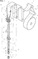
Figure 1 is a schematic view of a packaging apparatus having a package forming unit according to the present invention, with parts removed for clarity; -
Figure 2 is a schematic sectionized side view of a package forming unit according to the present invention, with parts removed for clarity; -
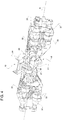
Figure 3 is a perspective front view of a detail of the package forming unit ofFigure 2 , with parts removed for clarity; -
Figure 4 is a perspective back view of a portion of the detail ofFigure 3 , with parts removed for clarity; and -
Figure 5 is a perspective back view of the detail ofFigure 3 , with parts removed for clarity. - Number 1 indicates as a whole a packaging apparatus for producing
sealed packages 2 of a pourable food product, such as fruit juice, pasteurized milk, wine, tomato sauce, etc., from atube 3 of a web 4 of packaging material. Eachpackage 2 comprises a pair oftransversal sealing bands 5 and alongitudinal seal 6. - Web 4 of packaging material has a multilayer structure (not shown), and comprises a layer of fibrous material, normally paper, covered on both sides with respective layers of heat-seal plastic material, e.g. polyethylene.
- Preferably, web 4 also comprises a layer of gas- and light-barrier material, e.g. aluminum foil or ethylene vinyl alcohol (EVOH) film, and at least a first and a second layer of heat-seal plastic material. The layer of gas- and light-barrier material is superimposed on the first layer of heat-seal plastic material, and is in turn covered with the second layer of heat-seal plastic material. The second layer of heat-seal plastic material forms the inner face of
package 2 eventually contacting the food product. - Furthermore, web 4 also comprises a repeated pattern, in particular a plurality of equally spaced images or decorations on the face of the layer of fibrous material facing the outside of the packages.
- With particular reference to
Figure 1 , packaging apparatus 1 comprises: - conveying means 7 for advancing at least web 4 along its longitudinal axis along a web advancement path P from a
delivery station 8 to a tube forming station 9, at which, in use, web 4 is formed intotube 3; - an
isolation chamber 10 separating an inner environment, in particular an inner aseptic environment, from an outer environment; - a
tube forming device 14 extending along a longitudinal axis L, in particular having a vertical orientation, and being arranged, in particular at tube forming station 9, at least partially, preferably fully, withinisolation chamber 10 and being adapted to formtube 3 from the, in use, advancing web 4; - a
sealing device 15 at least partially arranged withinisolation chamber 10 and being adapted to longitudinallyseal tube 3 formed bytube forming device 14; - filling means 16 for continuously filling
tube 3 formed bytube forming device 14 with the pourable product; and - a
package forming unit 17 adapted to formpackages 2 from the, in use, advancingtube 3 formed bytube forming device 14 and filled byfilling means 16. - Preferably, packaging apparatus 1 also comprises a sterilizing unit adapted to sterilize the, in use, advancing web 4 at a sterilization station, in particular the sterilization station being arranged upstream of tube forming station 9 along path P.
- With particular reference to
Figure 1 ,conveying means 5 are also adapted toadvance tube 3 formed bytube forming device 14 along its longitudinal axis along a respective tube advancement path Q, in particular fromtube forming device 14 topackage forming unit 17. - Preferentially,
conveying means 5 are also adapted to at least partially advancetube 3 and any intermediate oftube 3 along path Q. In particular, with the wording intermediates oftube 3 any configuration of web 4 is meant prior to obtaining the tube structure and after folding web 4 bytube forming device 14 has started. In other words, the intermediates oftube 3 are a result of the gradual folding of web 4 so as to obtaintube 3. - In particular, operation of conveying means 5 and operation of
package forming unit 17 are synchronized with respect to one another. - Preferably,
package forming unit 17 is arranged downstream ofisolation chamber 10 and oftube forming device 14 along path Q. Even more preferably,package forming unit 17 is arranged belowisolation chamber 10 andtube forming device 14. - Preferentially,
package forming unit 17 comprises: - a plurality of jaw assemblies 18 (only one shown in
Figure 2 ), each having onerespective jaw 19 and onerespective counter-jaw 20 for forming in cooperation with one another apackage 2 from the, in use, advancingtube 3; - at least a
first chain conveyor 21 configured to advancejaws 19 along a first endless path R; and - at least a
second chain conveyor 22 configured to advancecounter-jaws 20 along a second endless path S, in particular distinct (different) from first endless path R. - In more detail, first endless path R and second endless path S comprise respectively an operative portion R1 and an operative portion S1 at which respectively jaws 19 and
counter-jaws 20 advance, in use, parallel and adjacent to and in the same direction oftube 3 and interact with, in particular contact, in use,tube 3. In particular,jaws 19 advancing along operative portion R1 cooperate with therespective counter-jaws 20 advancing along operative portion S1 for forming therespective packages 2. Even more particular, eachjaw 19 and therespective counter-jaw 20 are configured to contact, in use,tube 3, in particular when advancing along respectively operative portion R1 and operative portion S1, from opposite sides thereof. - In even more detail, first endless path R and second endless path S also have respectively a return portion R2 and a return portion S2 at which respectively jaws 19 and
counter-jaws 20 are distanced fromtube 3 advancing along path Q. In particular, eachjaw 19 advancing along return portion R2 and therespective counter-jaw 20 advancing along return portion S2 are taken back to respectively operative portion R1 and operative portion S1, in particular so as to form, in use, anew package 2. - With particular reference to
Figure 2 ,chain conveyor 21 andchain conveyor 22 are arranged parallel to and spaced apart from one another, in particular leaving agap 26 through which, in use,tube 3 advances. - More specifically,
chain conveyor 21 andchain conveyor 22 each comprises a respective operative branch 27 (only partially shown) for defining respectively operative portion R1 and operative portion S1. In particular,operative branches 27 face one another. - Even more specifically,
chain conveyor 21 andchain conveyor 22 each comprises arespective return branch 28 for defining respectively return portion R2 and return portion S2. In particular, return branches 28 (only partially shown) face away from one another. - More specifically,
chain conveyor 21 comprises a plurality of elongated main bodies 29 (only one shown inFigure 2 ) each one carrying onerespective jaw 19, in particular eachmain body 29 extends along an axis A transversal to first endless path R. - Preferentially,
main bodies 29 are coupled to (connected to) one another so as to define an endless chain, in particularmain bodies 29 define mutually articulated links of the above-mentioned endless chain. - Preferentially,
chain conveyor 21 also comprises at least a pair of endless tracks 30 (only one shown inFigure 2 ) having a substantially vertical orientation and being arranged parallel to and spaced apart from one another and being configured to guide main bodies 29 (i.e.main bodies 29 move, in use, along endless tracks 30). In particular, eachendless track 30 carries a portion of the respectiveoperative branch 27 and therespective return branch 28. - More specifically, as shown in
Figures 3 to 5 , eachmain body 29 comprises afirst end portion 31 and asecond end portion 32 opposite tofirst end portion 31. Eachfirst end portion 31 is coupled to oneendless track 30 and the respectivesecond end portion 32 is coupled to the otherendless track 30. - Furthermore, each
main body 29 comprises a plurality ofroller elements 33, arranged in the proximity of the respectivefirst end portion 31 and the respectivesecond end portion 32 and engaging with one respectiveendless track 30 of the pair of endless tracks, in particular being configured to run on (being guided by) the respectiveendless track 30 in a manner known as such. - As
chain conveyor 22 is similar tochain conveyor 21, we will only describe the differences betweenchain conveyor 21 andchain conveyor 22. - In particular,
chain conveyor 22 differs fromchain conveyor 21 in that the respective main bodies ofchain conveyor 22 carry therespective counter-jaws 20. Additionally, the respective axes A are transversal to second endless path S. - With particular reference to
Figures 2 to 5 , eachjaw 19 comprises a respective half-shell 34 being adapted to contact, in use,tube 3, in particular from a first side thereof, and therespective counter-jaw 20 comprises a respective counter-half-shell 35, in particular being complementary to the respective half-shell 34, and being adapted to contact, in use,tube 3, in particular from a second side thereof opposite to the first side. In particular, each half-shell 34 and the respective counter-half-shell 35 are adapted to form and shape in cooperation therespective package 2. - In particular, each half-
shell 34 and each counter-half-shell 35 is adapted to be controlled between a respective working position in which the respective half-shell 34 and the respective counter-half-shell 35 contact, in use,tube 3 and a respective rest position in which the respective half-shell 34 and the respective counter-half-shell 35 are detached from tube 3 (they do not contact tube 3). - Even more particular, each half-
shell 34 and each counter-half-shell 35 is adapted to be controlled into the working position with respectively therespective jaw 19 and the respective counter-jaw 20 advancing, in use, along respectively operative portion R1 and operative portion S1. - More specifically, each half-
shell 34 and each counter-half-shell 35 is pivotably mounted to the respectivemain body 29, in particular in the area of acentral portion 36, in particular interposed between the respectivefirst end portion 31 and the respectivesecond end portion 32, of the respectivemain body 29. - Furthermore, each
jaw 19 and each counter-jaw 20 comprises a respectivecam follower element 37 coupled to the respective half-shell 34 or the respective counter-half-shell 35 and being adapted to interact with a cam body 38 (known as such and not further described) of package forming unit 17 (only partially shown inFigures 3 and5 to the extend necessary for the comprehension of the invention) so as to control the respective half-shell 34 or the respective counter-half-shell 35 between the respective working position and the respective rest position. - With particular reference to
Figures 2 to 5 , eachjaw 19 also comprises one of a sealing element or a counter-sealing element (in the example shown acounter-sealing element 43 and therespective counter-jaw 20 comprises the other one of a sealing element or a counter-sealing element (in the example shown a sealing element 44). In particular, each sealingelement 44 and the respectivecounter-sealing element 43 are adapted totransversally seal tube 3 in a known manner, in use, betweenadjacent packages 2, in particular so as to form acommon sealing band 45 between two adjacent packages 2 (seeFigure 1 ). - Preferably, each sealing
element 44 and eachcounter-sealing element 43 is mounted to the respectivemain body 29, in particular in the area of the respectivecentral portion 36. - In the specific example shown, each sealing
element 44 and eachcounter-sealing element 43 is arranged downstream of respectively counter-half-shell 35 and half-shell 34 along respectively first endless path S and second endless path R. - In a preferred embodiment, each
jaw 19 and the respective counter-jaw 20 also comprises one of a cutting element (not shown and known as such) or a counter-cutting element (not shown and known as such) for transversally cuttingtube 3 betweenadjacent packages 2, in particular along the respectivecommon sealing band 45 so as to separateadjacent packages 2 from one another and to obtain therespective sealing bands 5 of the two adjacentrespective packages 2. - With particular reference to
Figure 3 to 5 , eachjaw assembly 18 further comprises apair 46 ofinteraction tabs 47 being adapted to interact, in use, with advancingtube 3 from opposite sides thereof, in particular for exerting a pulling force on, in use, advancingtube 3, even more particular for at least partially controlling advancement oftube 3, and being controllable (moveable) between a first limit configuration and a second limit configuration. - In particular, each
pair 46 ofinteraction tabs 47 is configured to control advancement oftube 3 such that the tube of packaging material is in "register", meaning thattube 3 is formed and sealed, and in particular cut, at the intended region of the repeated pattern (in other words,tube 3 is advanced in such a manner that thepackage 2 obtained after sealing and, in particular after cutting, has the respective repeated pattern). - In other words, each
pair 46 ofinteraction tabs 47 is adapted to exert a controlled pulling force ontube 3 so as to "pull"tube 3 in a downstream direction along path Q. - Furthermore,
interaction tabs 47 are also configured to foldtube 3 by varying amounts towardscommon sealing band 45. - In particular, the controlled pulling force is dependent on how each
pair 46 ofinteraction tabs 47 is controlled between the respective first limit configuration and the respective second limit configuration, i.e. the position of theinteraction tabs 47 between the first limit configuration and the second limit configuration. - Preferentially, with the
respective pair 46 ofinteraction tabs 47 being in the respective first limit configuration therespective interaction tabs 47 are, in use, detached (distanced) fromtube 3 advancing along path Q, i.e. therespective interaction tabs 47 are not in contact withtube 3 and, thus, do not exert any pulling force ontube 3. In other words, when controlling therespective pair 46 into the respective first limit configuration therespective interaction tabs 47 are positioned such that they do not interact withtube 3 advancing along path P. - Preferably, with the
respective pair 46 being in the respective second limit configuration therespective interaction tabs 47 are, in use, in contact withtube 3 advancing along path Q, in particular when being controlled into the second limit configuration therespective interaction tabs 47 exert a maximum pulling force ontube 3. - Furthermore, each
pair 46 ofinteraction tabs 47 is configured such to be controllable between the first limit configuration and the second limit configuration so as to control the pulling force exerted by therespective interaction tabs 47 ontotube 3. - Furthermore, each
jaw assembly 18 also comprises anactuation device 48 having arespective cam follower 49 adapted to interact with a cam arrangement 50 (only partially shown to the extent necessary for the comprehension of the invention) ofpackage forming unit 17 and being coupled to therespective pair 46 ofinteraction tabs 47 for controlling, in particular continuously controlling, therespective pair 46 ofinteraction tabs 47 between the respective first limit configuration and the respective second limit configuration. - Preferentially, each
cam follower 49 is controllable between a first limit position and a second limit position in which therespective pair 46 ofinteraction tabs 47 is respectively in its respective first limit configuration and its respective second limit configuration. - Preferably, each
actuation device 48 also comprises atransmission assembly 51, in particular having an articulated inverted parallelogram configuration, coupled to therespective cam follower 49 and therespective pair 46 ofinteraction tabs 47 and configured to simultaneously transfer movement of therespective cam follower 49 induced by the interaction withcam arrangement 50 to therespective pair 46 ofinteraction tabs 47. - Preferentially, each
pair 46 ofinteraction tabs 47 and therespective actuation device 48 are associated to, in particular are part of, one of therespective jaw 19 and counter-jaw 20 (in the specific case shown of the respective jaw 19). Accordingly, eachpair 46 ofinteraction tabs 47 and therespective actuation device 48 are configured to advance along first endless path R or second endless path S, in the specific example shown along first endless path R. In particular, eachpair 46 ofinteraction tabs 47 is configured to interact, in use, withtube 3, when advancing along the respective operative portion R1 or the respective operative portion S1. - Preferentially, each
actuation device 48 also comprises a biasing assembly configured to bias therespective pair 46 ofinteraction tabs 47 into the respective first limit configuration, i.e.cam arrangement 50 is configured such to control therespective pair 46 ofinteraction tabs 47 against the action of the respective biasing assembly between the respective first limit configuration and the second limit configuration. - With particular reference to
Figure 3 , eachpair 46 ofinteraction tabs 47 is mounted to one respectivemain body 29, in particular to a front side ofmain body 29, which, in particular, in use, faces advancingtube 3 when, in use, therespective pair 46 ofinteraction tabs 47 interacts withtube 3. - In more detail, each
respective interaction tab 47 of eachpair 46 is pivotally mounted to the respectivemain body 29. - Preferentially, each
interaction tab 47 is adapted to angularly move around a respective rotation axis, in particular being normal to the respective axis A, between a respective outer limit position in which therespective interaction tab 47 is, in use, distanced from (not in contact with)tube 3 and a respective inner limit position in which therespective interaction tab 47 is, in use, in contact withtube 3. - In particular, the respective first limit configuration and the respective second limit configuration of each
pair 46 ofinteraction tabs 47 is defined by therespective interaction tabs 47 being respectively in the outer limit position and the inner limit position. - In more detail, the pulling force exerted, in use, by each
pair 46 ofinteraction tabs 47 interacting withtube 3 is dependent on the angular position of therespective interaction tabs 47. In particular, the pulling force is maximum with therespective interaction tabs 47 being angularly positioned in their respective inner limit position. - More specifically, the
respective interaction tabs 47 of eachpair 46 are arranged adjacent to and at opposite lateral sides of the respective half-shell 34 or the counter-half-shell 35. In particular, therespective interaction tabs 47 are arranged symmetrically with respect to the respective half-shell 34 or the respective counter-half-shell 35. - Even more specifically, the
respective interaction tabs 47 of eachpair 46 are arranged along a zone interposed between the respectivecounter-sealing element 43 or the respective sealing element 44 (in the specific case shown, the counter-sealing element 43) and the respective half-shell 34 or the respective counter-half-shell 35 (in the specific case shown the half-shell 34). - Furthermore, each
interaction tab 47 comprises arespective engagement surface 56 adapted to engagetube 3 at varying contact angles in dependence of the angular position of therespective interaction tab 47. - With particular reference to
Figures 4 and5 , eachactuation device 48 is connected to the respectivemain body 29, in particular at a respective back side opposite to the respective front side. - With particular reference to
Figures 3 and5 ,cam arrangement 50 comprises: - a main cam portion (not shown and known as such) configured to interact with
actuation devices 48, inparticular cam followers 49, and to control through the interaction withactuation devices 48, inparticular cam followers 49, therespective pairs 46 ofinteraction tabs 47 between the first limit configuration and the second limit configuration, in particular with therespective jaw 19 or the respective counter-jaw 20 advancing along respective operative portion R1 and operative portion S1; and - an
initial cam portion 57 arranged upstream of the main cam portion along first endless path R or second endless path S (depending on whetherpair 46 is associated to therespective jaw 19 or the respective counter-jaw 20) for interacting withactuation devices 48, inparticular cam followers 49, such to control therespective pairs 46 ofinteraction tabs 47 into the first limit configuration. - Preferentially,
cam arrangement 50 is interposed between the respectiveendless tracks 30. Preferably, the main cam portion extends substantially parallel to path Q. - In more detail, the main cam portion comprises an engagement surface along which
cam followers 49 advance, in use, so as to control thepairs 46 ofinteraction tabs 47 between the respective first limit configurations and the second limit configurations, in particular when, in use, advancing along a downstream section of the respective operative portion R1 or the respective operative portion S1. - Preferably, the main cam portion comprises at least one moveable section coupled to an actuation device (known as such and not further described) of
cam arrangement 50 adapted to vary the position of the moveable section so as to control the angular positions ofinteraction tabs 47. Thus, the force exerted bypairs 46 ofinteraction tabs 47 interacting, in use, withtube 3 is controlled by moving the moveable section in a manner known as such. - In more detail,
initial cam portion 57 is configured to interact withcam followers 49 such thatinteraction tabs 47 are arranged at a defined angular position in whichinteraction tabs 47 are detached fromtube 3. - In particular,
initial cam portion 57 is configured to positioncam followers 49 in the respective first limit position. - Advantageously,
initial cam portion 57 comprises: - a guiding
surface 58 for guidingcam followers 49 so as to define the first limit position of cam followers 49 (and, accordingly, to define the first limit configuration ofpairs 46 of interaction tabs 47); and - a delimiting
surface 59 adjacent to and facing guidingsurface 58 and configured to limit movement ofcam followers 49 along a direction D transversal to and away from guidingsurface 58. - In particular, delimiting
surface 59 allows to limit movement ofcam followers 49 so as to ensure thatpairs 46 ofinteraction tabs 47 remain in the first limit configuration (and do not accidentally move towards the second limit configuration). In more detail, delimitingsurface 59 allows to limit movement ofcam followers 49 so as to ensure thatinteraction tabs 47 remain in an angular position in whichinteraction tabs 47 are distanced (detached / do not contact)tube 3, in particular when advancing along an upstream section of the respective operative portion R1 or the respective operative portion S1; the upstream section being arranged upstream of the respective downstream section along the respective first endless path R or the respective second endless path S. - It should be noted that without delimiting
surface 59pairs 46 ofinteraction tabs 47 could move in a non-controllable manner towards the second limit configuration. This again could lead to a positioning of therespective interaction tabs 47 so that these could get in a non-controlled manner into contact withtube 3. - Preferentially, delimiting
surface 59 is configured to limit movement ofcam follower 49 along direction D transversal to an advancement path along whichcam followers 49 advance, in use (the advancement path being substantially first endless path R or second endless path S, i.e. the advancement path is determined by movement of the respectivemain body 29 and the interaction with cam arrangement 50). - Preferably, guiding
surface 58 is placed directly upstream of the engagement surface of the main cam portion along first endless path R or second endless path S. In other words, whencam followers 49 advance, in use, along their respective advancement path atfirst cam followers 49 engage with guidingsurface 58 and then with the engagement surface of the main cam portion. - In further detail,
initial cam portion 57 comprises afirst cam bar 60 carrying the guidingsurface 58 and asecond cam bar 61 spaced apart from and arranged substantially parallel tocam bar 60 and carrying the delimitingsurface 59. - In use, web 4 advances along path P through
isolation chamber 10 and is formed intotube 3 advancing along path Q. -
Tube 3 advances along path Q to and throughpackage forming unit 17. -
Package forming unit 17forms packages 2 from advancingtube 3. - In more detail,
jaw assemblies 18 interact withtube 3 for formingpackages 2. - In even more detail, each
jaw 19 and the respective counter-jaw 20 advance along respectively first endless path R and second endless path S. Eachjaw 19 and the respective counter-jaw 20 interact withtube 3 while advancing respectively along operative portion R1 and operative portion S1. - More specifically, while each
jaw 19 advances along operative portion R1 and while the respective counter-jaw 20 advances along operative portion S1, the respective half-shell 34 and the respective counter-half-shell 35 are controlled into the respective working position for forming incooperation tube 3 for obtaining therespective package 2. Preferentially, therespective sealing element 44 and the respectivecounter-sealing element 43seal tube 3 so as to form the respectivecommon sealing band 45. Preferably, after formation of the respectivecommon sealing band 45 the respective cutting element and the respective counter-cutting element cooperate so as to transversally cuttube 3 along the respectivecommon sealing band 45 so as to separate the respective twoadjacent packages 2. - Furthermore, each
pair 46 ofinteraction tabs 47 interacts withtube 3, in particular for exerting the required pulling force for keeping the repeated patterns "in register". - In particular, during advancement of the respective jaw 19 (or in the alternative case of the respective counter-jaw 20) the
respective pair 46 ofinteraction tabs 47 are controlled between the first limit configuration and the second limit configuration, in particular by controlling therespective cam follower 49 between the respective first limit position and the second limit position. - In particular,
cam follower 49 interacts withcam arrangement 50 so as to control therespective pair 46 ofinteraction tabs 47. - Prior to interaction of the
respective jaw 19 withtube 3, therespective pair 46 ofinteraction tabs 47 is controlled into the respective first limit configuration by therespective cam follower 49 being guided by guidingsurface 58 delimitingsurface 59. In particular, guidingsurface 58 guarantees that therespective cam follower 49 remains in the first limit position. Then, therespective cam follower 49 is guided, in particular in a controlled manner, by the engagement surface of the main cam portion so as to control therespective pair 46 ofinteraction tabs 47 between the respective first limit configuration and the respective second limit configuration in a manner known as such and not further described. - The advantages of
package forming unit 17 according to the present invention will be clear from the foregoing description. - In particular, by providing delimiting
surface 59 it is possible to guarantee thatcam followers 49 remain in the first limit position prior to interaction ofcam followers 49 with the main cam portion. Thus, this guarantees that pairs 46 ofinteraction tabs 47 remain in the first limit configuration prior to interaction ofcam followers 49 with the main cam portion. This allows avoiding that therespective interaction tabs 47 unintentionallycontact tube 3. - Clearly, changes may be made to packaging apparatus 1, in particular
package forming unit 17 as described herein without, however, departing from the scope of protection as defined in the accompanying claims.
Claims (6)
- A package forming unit (17) for continuously forming sealed packages (2) from a tube (3) advancing along a tube advancement path (Q) comprising:- at least one jaw assembly (18) having one respective jaw (19) and one respective counter-jaw (20) for forming in cooperation with one another a respective package (2) from the, in use, advancing tube (3);- at least a first chain conveyor (21) for advancing the jaw (19) along a first endless path (R); and- at least a second chain conveyor (22) for advancing the counter-jaw (20) along a second endless path (S);wherein the jaw assembly (18) further comprises:- at least one pair (46) of interaction tabs (47) associated to one of the respective jaw (19) or the respective counter-jaw (20) and being adapted to interact, in use, with the tube (3) from opposite sides thereof and being controllable between a first limit configuration in which the respective interaction tabs (47) are configured to be, in use, detached from the tube (3) and a second limit configuration in which the respective interaction tabs (47) are configured to be, in use, in contact with the tube (3); and- an actuation device (48) having a cam follower (49) adapted to interact with a cam arrangement (50) of the package forming unit (17) and being coupled to the pair (46) of interaction tabs (47) for controlling the pair (46) of interaction tabs (47) between the first limit configuration and the second limit configuration;wherein the cam arrangement (50) comprises:- an initial cam portion (57) for interacting with the actuation device (48) such to control the pair (46) of interaction tabs (47) in the first limit configuration; and- a main cam portion arranged downstream of the initial cam portion (57) along the respective first endless path (R) or the respective second endless path (S) and being configured to control the cam follower (49) such to at least control the pair (46) of interaction tabs (47) between the first limit configuration and the second limit configuration;wherein the initial cam portion (57) comprises a guiding surface (58) for guiding the cam follower (49) so as to define the first limit configuration of the pair (46) of interaction tabs (57);
characterized in that the initial cam portion (57) further comprises a delimiting surface (59) adjacent to and facing the guiding surface (58) and configured to limit movement of the cam follower (49) along a direction (D) transversal to and away from the guiding surface (58). - The package forming unit according to claim 1, wherein the cam follower (49) advances, in use, along a respective advancement path and the delimiting surface (59) is configured to limit movement of the cam follower (49) into the direction (D) transversal to the advancement path.
- The package forming unit according to claim 1 or 2, wherein the jaw (19) comprises a half-shell (34) and the counter-jaw (20) comprises a counter-half-shell (35);
wherein the half-shell (34) and the counter-half-shell (35) are configured to form in cooperation with one another the package (2) from tube (3);
wherein the respective interaction tabs (47) of the pair (46) of interaction tabs (47) are arranged adjacent to and at opposite lateral sides of one of the half-shell (34) or the counter-half-shell (35). - The package forming unit according to any one of the preceding claims, wherein each one of the first conveyor device (21) and the second conveyor device (22) comprises at least one respective elongated main body (29) for carrying respectively the jaw (19) and the counter-jaw (20);
wherein each interaction tab (47) of the pair (46) of interaction tabs (47) is mounted to one respective main body (49) and is adapted to angularly move around a respective rotation axis between a respective outer limit position and a respective inner limit position;
wherein the first limit configuration and the second limit configuration are defined by the interaction tabs (47) of the pair (46) of interaction tabs (47) being respectively in the outer limit position and the inner limit position. - The package forming unit according to any one of the preceding claims, wherein the actuation device (48) comprises a transmission assembly (51) coupled to the cam follower (49) and the pair (46) of interaction tabs (47) and configured to, in use, simultaneously transfer movement of the cam follower (49) induced by the interaction of the cam follower (49) with the cam arrangement (50) to the pair (46) of interaction tabs (47).
- A packaging apparatus for forming sealed packages (2) of a pourable food product from a tube (3) of a web (4) of packaging material comprising:- an isolation chamber (10) separating an inner environment from an outer environment;- a tube forming device (14) being at least partially arranged within the isolation chamber (10) and being adapted to form the tube (3) from the, in use, advancing web (4) of packaging material;- conveying means (7) adapted to advance the web (4) of packaging material along a web advancement path (P) to the tube forming device (14) and adapted to advance the tube (3) from the tube forming device (14) along a tube advancement path (Q);- a sealing device (15) at least partially arranged within the isolation chamber (10) and being adapted to longitudinally seal the tube (3) formed by the tube forming device (14);- filling means (16) for continuously filling the tube (3) formed by the tube forming device (14) with the pourable product; and- a package forming unit (17) according to any one of the preceding claims being arranged downstream of the tube forming device (14) along the tube advancement path (Q) and being adapted to form the packages (2) from the tube (3).
Applications Claiming Priority (1)
| Application Number | Priority Date | Filing Date | Title |
|---|---|---|---|
| EP17207015 | 2017-12-13 |
Publications (1)
| Publication Number | Publication Date |
|---|---|
| EP3498616A1 true EP3498616A1 (en) | 2019-06-19 |
Family
ID=60673368
Family Applications (1)
| Application Number | Title | Priority Date | Filing Date |
|---|---|---|---|
| EP18210494.3A Withdrawn EP3498616A1 (en) | 2017-12-13 | 2018-12-05 | A package forming unit for forming sealed packages |
Country Status (3)
| Country | Link |
|---|---|
| EP (1) | EP3498616A1 (en) |
| CN (2) | CN210162289U (en) |
| WO (1) | WO2019115315A1 (en) |
Cited By (1)
| Publication number | Priority date | Publication date | Assignee | Title |
|---|---|---|---|---|
| EP3943400A1 (en) * | 2020-07-23 | 2022-01-26 | Tetra Laval Holdings & Finance S.A. | Package forming unit, packaging apparatus having a package forming unit and method for forming packages |
Families Citing this family (1)
| Publication number | Priority date | Publication date | Assignee | Title |
|---|---|---|---|---|
| IT202300017055A1 (en) * | 2023-08-09 | 2025-02-09 | Tetra Laval Holdings & Finance | UNIT FOR FORMING PACKETS CONTAINING A POURABLE PRODUCT AND METHOD FOR FORMING PACKETS CONTAINING A POURABLE PRODUCT |
Citations (4)
| Publication number | Priority date | Publication date | Assignee | Title |
|---|---|---|---|---|
| EP0887265A1 (en) * | 1997-06-27 | 1998-12-30 | Tetra Laval Holdings & Finance SA | Packaging unit for continuously producing sealed packages, containing pourable food products, from a tube of packaging material |
| WO2005012102A1 (en) | 2003-07-25 | 2005-02-10 | Tetra Laval Holdings & Finance Sa | Forming method and unit for producing sealed packages |
| EP1832518A1 (en) * | 2006-03-07 | 2007-09-12 | Tetra Laval Holdings & Finance S.A. | Packing machine for producing sealed packages of pourable food products |
| EP2311738A1 (en) * | 2009-10-15 | 2011-04-20 | Tetra Laval Holdings & Finance SA | A packaging machine for producing sealed packages of pourable food products |
-
2018
- 2018-12-05 EP EP18210494.3A patent/EP3498616A1/en not_active Withdrawn
- 2018-12-05 WO PCT/EP2018/083668 patent/WO2019115315A1/en not_active Ceased
- 2018-12-13 CN CN201822090550.3U patent/CN210162289U/en not_active Expired - Fee Related
- 2018-12-13 CN CN201811523476.8A patent/CN109941477A/en active Pending
Patent Citations (4)
| Publication number | Priority date | Publication date | Assignee | Title |
|---|---|---|---|---|
| EP0887265A1 (en) * | 1997-06-27 | 1998-12-30 | Tetra Laval Holdings & Finance SA | Packaging unit for continuously producing sealed packages, containing pourable food products, from a tube of packaging material |
| WO2005012102A1 (en) | 2003-07-25 | 2005-02-10 | Tetra Laval Holdings & Finance Sa | Forming method and unit for producing sealed packages |
| EP1832518A1 (en) * | 2006-03-07 | 2007-09-12 | Tetra Laval Holdings & Finance S.A. | Packing machine for producing sealed packages of pourable food products |
| EP2311738A1 (en) * | 2009-10-15 | 2011-04-20 | Tetra Laval Holdings & Finance SA | A packaging machine for producing sealed packages of pourable food products |
Cited By (5)
| Publication number | Priority date | Publication date | Assignee | Title |
|---|---|---|---|---|
| EP3943400A1 (en) * | 2020-07-23 | 2022-01-26 | Tetra Laval Holdings & Finance S.A. | Package forming unit, packaging apparatus having a package forming unit and method for forming packages |
| WO2022017745A1 (en) * | 2020-07-23 | 2022-01-27 | Tetra Laval Holdings & Finance S.A. | Package forming unit, packaging apparatus having a package forming unit and method for forming packages |
| JP2023535414A (en) * | 2020-07-23 | 2023-08-17 | テトラ ラバル ホールディングス アンド ファイナンス エス エイ | PACKAGE FORMING UNIT, PACKAGING APPARATUS HAVING PACKAGE FORMING UNIT AND PACKAGE FORMING METHOD |
| US12043442B2 (en) | 2020-07-23 | 2024-07-23 | Tetra Laval Holdings & Finance S.A. | Package forming unit, packaging apparatus having a package forming unit and method for forming packages |
| JP7787871B2 (en) | 2020-07-23 | 2025-12-17 | テトラ ラバル ホールディングス アンド ファイナンス エス エイ | Package forming unit, packaging device having package forming unit, and package forming method |
Also Published As
| Publication number | Publication date |
|---|---|
| CN210162289U (en) | 2020-03-20 |
| WO2019115315A1 (en) | 2019-06-20 |
| CN109941477A (en) | 2019-06-28 |
Similar Documents
| Publication | Publication Date | Title |
|---|---|---|
| EP2586715B1 (en) | Feeding unit for feeding sealed packs of pourable food products and packaging machine comprising such a feeding unit | |
| US9637262B2 (en) | Folding unit for pourable food product packaging machines | |
| US9409368B2 (en) | Folding unit for pourable food product packaging machines | |
| US20190160758A1 (en) | A packaging apparatus for forming sealed packages from a tube of packaging material | |
| US10449728B2 (en) | Forming assembly and method for forming a plurality of sealed packs for pourable food products starting from a tube of packaging material | |
| US12043442B2 (en) | Package forming unit, packaging apparatus having a package forming unit and method for forming packages | |
| US10195790B2 (en) | Forming assembly and method for forming a plurality of sealed packs for pourable food products starting from a tube of packaging material | |
| EP1509453B1 (en) | Forming jaw for producing a succession of sealed packages from a tube of sheet packaging material | |
| WO2019115315A1 (en) | A package forming unit for forming sealed packages | |
| EP1325868A1 (en) | Packaging unit for continuously producing sealed packages, containing pourable food products, from a tube of packaging material | |
| EP4265533A1 (en) | Infeed conveyor for a folding apparatus, folding apparatus having an infeed conveyor and packaging machine having a folding apparatus | |
| EP1125847B1 (en) | Packaging unit for continuously producing sealed packages of pourable food products | |
| EP4454864A1 (en) | Package forming apparatus for a packaging machine and packaging machine for forming packages filled with a pourable product | |
| EP4410522B1 (en) | Package forming apparatus for a packaging machine and packaging machine for forming packages filled with a pourable product | |
| EP4410523B1 (en) | Package forming apparatus for a packaging machine and packaging machine for forming packages filled with a pourable product | |
| EP4410690B1 (en) | Package forming apparatus for a packaging machine and packaging machine for forming packages filled with a pourable product | |
| EP3351478A1 (en) | Forming member for controlling the volume of packs of pourable food products formed from a tube of packaging material | |
| EP3020642A1 (en) | Folding unit for producing folded packages from sealed packs | |
| WO2024251614A1 (en) | Package forming apparatus and packaging machine for forming packages |
Legal Events
| Date | Code | Title | Description |
|---|---|---|---|
| PUAI | Public reference made under article 153(3) epc to a published international application that has entered the european phase |
Free format text: ORIGINAL CODE: 0009012 |
|
| STAA | Information on the status of an ep patent application or granted ep patent |
Free format text: STATUS: THE APPLICATION HAS BEEN PUBLISHED |
|
| AK | Designated contracting states |
Kind code of ref document: A1 Designated state(s): AL AT BE BG CH CY CZ DE DK EE ES FI FR GB GR HR HU IE IS IT LI LT LU LV MC MK MT NL NO PL PT RO RS SE SI SK SM TR |
|
| AX | Request for extension of the european patent |
Extension state: BA ME |
|
| STAA | Information on the status of an ep patent application or granted ep patent |
Free format text: STATUS: REQUEST FOR EXAMINATION WAS MADE |
|
| 17P | Request for examination filed |
Effective date: 20191219 |
|
| RBV | Designated contracting states (corrected) |
Designated state(s): AL AT BE BG CH CY CZ DE DK EE ES FI FR GB GR HR HU IE IS IT LI LT LU LV MC MK MT NL NO PL PT RO RS SE SI SK SM TR |
|
| GRAP | Despatch of communication of intention to grant a patent |
Free format text: ORIGINAL CODE: EPIDOSNIGR1 |
|
| STAA | Information on the status of an ep patent application or granted ep patent |
Free format text: STATUS: GRANT OF PATENT IS INTENDED |
|
| INTG | Intention to grant announced |
Effective date: 20200424 |
|
| STAA | Information on the status of an ep patent application or granted ep patent |
Free format text: STATUS: THE APPLICATION IS DEEMED TO BE WITHDRAWN |
|
| 18D | Application deemed to be withdrawn |
Effective date: 20200905 |