EP3498606A1 - System and method for modifying the location of water impingement limits on an airfoil - Google Patents
System and method for modifying the location of water impingement limits on an airfoil Download PDFInfo
- Publication number
- EP3498606A1 EP3498606A1 EP18204985.8A EP18204985A EP3498606A1 EP 3498606 A1 EP3498606 A1 EP 3498606A1 EP 18204985 A EP18204985 A EP 18204985A EP 3498606 A1 EP3498606 A1 EP 3498606A1
- Authority
- EP
- European Patent Office
- Prior art keywords
- attack
- angle
- airfoil
- aircraft
- stabilizer
- Prior art date
- Legal status (The legal status is an assumption and is not a legal conclusion. Google has not performed a legal analysis and makes no representation as to the accuracy of the status listed.)
- Granted
Links
Images






Classifications
-
- B—PERFORMING OPERATIONS; TRANSPORTING
- B64—AIRCRAFT; AVIATION; COSMONAUTICS
- B64C—AEROPLANES; HELICOPTERS
- B64C13/00—Control systems or transmitting systems for actuating flying-control surfaces, lift-increasing flaps, air brakes, or spoilers
- B64C13/02—Initiating means
- B64C13/16—Initiating means actuated automatically, e.g. responsive to gust detectors
-
- B—PERFORMING OPERATIONS; TRANSPORTING
- B64—AIRCRAFT; AVIATION; COSMONAUTICS
- B64D—EQUIPMENT FOR FITTING IN OR TO AIRCRAFT; FLIGHT SUITS; PARACHUTES; ARRANGEMENT OR MOUNTING OF POWER PLANTS OR PROPULSION TRANSMISSIONS IN AIRCRAFT
- B64D15/00—De-icing or preventing icing on exterior surfaces of aircraft
-
- G—PHYSICS
- G05—CONTROLLING; REGULATING
- G05D—SYSTEMS FOR CONTROLLING OR REGULATING NON-ELECTRIC VARIABLES
- G05D1/00—Control of position, course, altitude or attitude of land, water, air or space vehicles, e.g. using automatic pilots
- G05D1/08—Control of attitude, i.e. control of roll, pitch, or yaw
- G05D1/0808—Control of attitude, i.e. control of roll, pitch, or yaw specially adapted for aircraft
-
- B—PERFORMING OPERATIONS; TRANSPORTING
- B64—AIRCRAFT; AVIATION; COSMONAUTICS
- B64C—AEROPLANES; HELICOPTERS
- B64C9/00—Adjustable control surfaces or members, e.g. rudders
- B64C2009/005—Ailerons
-
- B—PERFORMING OPERATIONS; TRANSPORTING
- B64—AIRCRAFT; AVIATION; COSMONAUTICS
- B64C—AEROPLANES; HELICOPTERS
- B64C2230/00—Boundary layer controls
Definitions
- the present disclosure relates generally to aircraft flight operations and, more particularly, to a system and method for modifying the water impingement limits on an airfoil of an aircraft.
- Ice can form on the surfaces of an aircraft in flight when water droplets impinge and freeze on the aircraft surfaces.
- the accretion of ice on certain aerodynamic surfaces can reduce the performance and handling characteristics of the aircraft. For example, ice accretion on the leading edges of the wings can alter the cross-sectional shape of the wings which can disrupt the flow of air over the wings, resulting in reduced lift capability of the wings, increased aerodynamic drag, added weight, and increased stall speed of the aircraft.
- Another method of addressing ice accretion on leading edges involves the use of a bleed air de-icing or anti-icing system in which hot air is bled from gas turbine engines of an aircraft.
- the bleed air is routed through spray tubes extending along the interior of the leading edges and is discharged in a manner to heat the wing surfaces.
- the bleed air may be periodically activated in a manner to maintain the surfaces of the leading edges above freezing to prevent the formation of ice, or to melt the ice to an extent that air flowing over the wings blows the ice off the wings.
- the extraction of bleed air from the engines reduces engine performance.
- the spray tubes and other hardware of a bleed air system add to the cost, complexity and weight of the aircraft.
- the above-noted needs associated with ice accretion on airfoils are specifically addressed and alleviated by the present disclosure which provides a system for modifying a location of a water impingement limit on an airfoil of an aircraft.
- the system includes a flight control computer configured to receive data representative of environmental parameters in an environment of a flight path of an aircraft.
- the flight control computer is configured to determine, based on the environmental parameters, an existence of icing conditions to which the aircraft is currently subjected or is predicted to be subjected.
- the flight control computer is configured to generate, based on the existence of icing conditions, a command signal for actuating a movable surface of the aircraft.
- the system further includes a surface actuator configured to receive the command signal from the flight control computer and adjust the movable surface in a manner causing an increase in an angle of attack of the airfoil to thereby modify a water impingement limit on the airfoil.
- the method includes sensing environmental parameters in an environment of a flight path of an aircraft, and determining, based on the environmental parameters, an existence of icing conditions to which the aircraft is currently subjected or is predicted to be subjected.
- the method includes adjusting, in response to determining the existence of icing conditions, at least one movable surface of the aircraft, and increasing an angle of attack of the airfoil in response to adjusting the movable surface to thereby cause a modification of a water impingement limit on the airfoil.
- a further example of the method includes sensing an air temperature and a droplet size of water droplets in an environment of a flight path of the aircraft, determining, based on the air temperature and the droplet size, an existence of icing conditions to which the aircraft is currently subjected or is predicted to be subjected, and upwardly deflecting, in response to determining the existence of icing conditions, at least one laterally symmetric pair of movable surfaces respectively coupled to the pair of wings.
- the method includes increasing a wing angle of attack of the wings in response to upwardly deflecting the laterally symmetric pair of movable surfaces to thereby cause a forward and downward shift of a water impingement upper limit on an upper surface of the wings and an aftward and downward shift of a water impingement lower limit on a lower surface of the wings.
- FIG. 1 shown in Figure 1 is a schematic diagram of a water impingement limit modification system 500 for modifying the location of the water impingement limits 144, 146 ( Figures 5-6 ) on at least one airfoil 110 ( Figure 2 ) of an aircraft 100 ( Figure 2 ). Modification of the location of the water impingement limits 144, 146 on an airfoil 110 results in the modification of the location of ice accretion limits 152, 154 ( Figures 7-8 ) on the airfoil 110.
- Modifying the location of the ice accretion limits 152, 154 reduces the negative effects of ice accretion 148 on the aerodynamics of air flowing over the airfoil 110. For example, modifying the location of the ice accretion limits 152, 154 reduces the extent of flow separation (not shown) over the airfoil 110 that may occur as a result of the ice accretion 148. In addition, modifying the location of the ice accretion limits 152, 154 reduces the negative effect of ice accretion 148 on the maximum lift coefficient 610 (e.g., Figure 9 ), and reduces the amount of aerodynamic drag generated by the ice accretion 148.
- the maximum lift coefficient 610 e.g., Figure 9
- the water impingement limits 144, 146 on an airfoil 110 are the locations defined by the tangent trajectories 142 ( Figures 5-6 ) of water droplets 406 ( Figures 4-6 ), in the flow of air moving over the airfoil 110.
- a forward portion or wing leading edge 130 of a wing 126 which has a suction side 136 (i.e., a wing upper surface having a relatively high degree of curvature, the side of lower pressure side), and a pressure side 138 (i.e., a wing 126 lower surface having a relatively low degree of curvature, the side of higher pressure).
- the suction side 136 has a suction side water impingement limit 144 and the pressure side 138 has a pressure side water impingement limit 146 which are each measured along the airfoil 110 surface relative to the highlight 134 of the airfoil 110.
- the highlight 134 of an airfoil 110 is the point furthest forward on the surface of the leading edge when the airfoil 110 is at an angle of attack of 0°.
- the suction side 136 and the pressure side 138 may have the same degree of curvature.
- orienting the horizontal tail at an angle of attack in which the stabilizer leading edge 116 is oriented in a downward direction generates low pressure or suction on the stabilizer lower side such that the stabilizer lower side is the suction side 136 (i.e., the side of lower pressure side) and the stabilizer upper side is the pressure side 138 (i.e., the side of higher pressure side).
- the suction side water impingement limit 144 and the pressure side water impingement limit 146 of an airfoil 110 are each located at a respective tangent trajectory 142 ( Figures 5-6 ) of a water droplet 406 ( Figures 4-6 ) of a given size that starts out upstream of the airfoil 110 in the freestream flow 132 (e.g., Figures 4-7 ), as described in greater detail below.
- the system 500 is configured to detect the existence of icing conditions such that when the aircraft 100 encounters or is predicted to encounter icing conditions, the system 500 is configured to increase the angle of attack ( Figure 6 ) of at least one airfoil 110 of the aircraft 100 in a manner causing the location of the water impingement limits 144, 146 ( Figures 5-6 ) to proactively shift at least partially away from the suction side 136 ( Figures 5-6 ), and shift more toward the pressure side 138 ( Figures 5-6 ).
- an increase in the wing angle of attack 128 causes a combination lowering and forward shifting of the suction side water impingement limit 144 relative to the highlight 134, and a combination lowering and aftward shifting of the pressure side water impingement limit 146 relative to the highlight 134.
- the shifting of the water impingement limits 144, 146 has the effect of shifting the location of the ice accretion limits 152, 154 ( Figures 7-8 ) at least partially away from the suction side 136 (i.e., area of high curvature) of the wing 126, which reduces the above-mentioned negative effects of ice accretion 148 on the aerodynamics of the wing 126.
- the system 500 includes a flight control computer 502 configured to receive data representative of environmental parameters 402 sensed in an environment 400 ( Figure 2 ) of a flight path 156 ( Figure 2 ) of an aircraft 100 ( Figure 2 ).
- the flight control computer 502 may include activation logic 504 configured to determine the existence of icing conditions based on the environmental parameters 402 and additionally, but optionally, based on aircraft state data 300.
- the flight control computer 502 determines the existence of icing conditions to which the aircraft 100 is currently subjected, or the existence of icing conditions to which the aircraft 100 is predicted to be subjected at some point along the flight path 156 of the aircraft 100.
- the flight control computer 502 may include angle of attack selection logic 506 for determining the amount by which the angle of attack of the airfoil 110 ( Figure 2 ) is to be increased.
- the flight control computer 502 is configured to generate one or more command signals 512 at the appropriate time for actuating one or more movable surfaces 202 (e.g., spoilers 218, ailerons 214, horizontal stabilizer 114, elevator 120, etc. - Figures 3 and 10-15 ) of the aircraft 100.
- the flight control computer 502 may immediately (e.g., within several seconds of detecting icing conditions) generate one or more command signals 512.
- the flight control computer 502 may be configured to wait until the aircraft 100 nears the predicted location of the icing conditions, and then generate command signals 512 preferably prior (e.g., within several seconds) to the time when the aircraft 100 enters the icing conditions.
- the system 500 further includes one or more surface actuators 200 configured to receive command signals 512 from the flight control computer 502 and, in response to the command signals 512, adjust one or more of the movable surfaces 202 in a manner causing an increase in the angle of attack of the airfoil 110 ( Figures 5-6 ) to thereby modify the water impingement limits 144, 146 ( Figures 5-6 ) on the airfoil 110.
- one or more surface actuators 200 configured to receive command signals 512 from the flight control computer 502 and, in response to the command signals 512, adjust one or more of the movable surfaces 202 in a manner causing an increase in the angle of attack of the airfoil 110 ( Figures 5-6 ) to thereby modify the water impingement limits 144, 146 ( Figures 5-6 ) on the airfoil 110.
- the flight control computer 502 may detect the existence of icing conditions, and may generate a command signal 512 causing existing spoiler actuators (not shown) to upwardly deflect the spoilers 218 ( Figure 11 ) and/or existing aileron actuators (not shown) to upwardly deflect the ailerons 214 ( Figure 12 ) in a manner causing the wing angle of attack 128 ( Figures 10-12 ) to increase by a relatively small amount (e.g., 0.5 to 4°), and resulting in a proactive shifting of the location of the water impingement limits 144, 146 ( Figures 5-6 ) at least partially away from the suction side 136 (e.g., Figures 5-6 ) of the wing 126 and at least partially toward the pressure side 138 (e.g., Figures 5-6 ), to thereby reduce the effects of ice accretion 148 ( Figures 7-8 ) on the aerodynamics of the air flowing over the wing 126.
- existing spoiler actuators not shown
- the aircraft 100 has one or more airfoils 110 (e.g., wings 126, horizontal stabilizer 114 - Figures 2-3 ) that may be subjected to ice accretion 148 ( Figures 7-8 ) when the aircraft 100 is in the icing conditions.
- the aircraft 100 additionally includes a plurality of movable surfaces 202 (e.g., spoilers 218, ailerons 214, etc. - Figure 3 ) for attitude and directional control of the aircraft 100.
- one or more of the movable surfaces 202 are temporarily actuated in a manner that increases the angle of attack of one or more of the airfoils 110 as a means for proactively shifting the location of the water impingement limits 144, 146 ( Figures 5-6 ) on the one or more airfoils 110 to thereby reduce the effects of ice accretion 148 ( Figure 7-8 on the one or more airfoils 110.
- icing conditions may occur in non-cloud conditions.
- icing conditions may occur at any time when water droplets 406 (e.g., liquid water - Figures 2 and 4-6 ) freeze upon impingement on an aircraft 100 surface, or freeze shortly after (e.g., within several seconds) impingement on an aircraft 100 surface.
- water droplets 406 e.g., liquid water - Figures 2 and 4-6
- freeze shortly after e.g., within several seconds
- the flight control computer 502 receives data representative of environmental parameters 402, and determines the existence of icing conditions presently occurring and/or predicted to occur along the aircraft 100 flight path 156 ( Figure 2 ).
- environmental parameters 402 include, but are not limited to, air temperatures 404 along the flight path 156 ( Figure 2 ), droplet size 408 of water droplets 406 ( Figure 2 ) in the atmosphere (e.g., in clouds 412 - Figure 2 ) along the flight path 156, and liquid water content 410 of clouds 412 along the flight path 156.
- Such environmental parameters 402 may be sensed by ground-based sensors and forward/or airborne sensors (e.g., onboard the aircraft 100) prior to and/or during the flight of the aircraft 100.
- the environmental parameters 402 may be periodically or continuously provided to the flight control computer 502.
- ground-based or airborne weather forecasting instrumentation may predict the occurrence of weather conducive to ice accretion 148 during the flight of the aircraft 100, and may provide such environmental parameter data to the flight control computer 502 prior to and/or during the flight of the aircraft 100.
- Information regarding the existence, location and/or severity of icing conditions encountered and reported by pilots of other aircraft 100 near the flight path 156 may also be manually or automatically entered into the flight control computer 502.
- air temperature 404 is the temperature of ambient air along the flight path 156 ( Figure 2 ) and may be periodically or continuously measured and provided to the flight control computer 502 by ground-based or airborne temperature measurement instrumentation.
- Droplet size 408 may also be periodically or continuously measured and provided to the flight control computer 502 to facilitate a determination of the existence of icing conditions. For example, upon receiving data indicating an air temperature 404 of 0°C or colder, and data indicating the presence of water droplets 406 ( Figure 2 ), the flight control computer 502 may determine that icing conditions exist.
- the flight control computer 502 may determine that icing conditions exist based on aircraft state data 300 including aircraft surface temperature 302 measurements lower than 0°C, and which may occur if the aircraft 100 has been exposed to air temperatures 404 below 0°C, and is later located in temperatures at or above 0°C while the aircraft surface temperature 302 is still below freezing.
- Measurement of aircraft surface temperature 302 may be periodically or continuously provided to the flight control computer 502 by temperature sensors (not shown) for monitoring the temperature of the airfoil 110 surface.
- temperature sensors may be mounted on the wing leading edge 130 ( Figure 4 ) of the wing 126 ( Figure 4 ), stabilizer leading edge 116 ( Figure 4 ) of the horizontal stabilizer 114 ( Figure 4 ), and/or at other locations on the airframe.
- clouds 412 may be comprised of supercooled water droplets which exist in liquid form at temperatures below 0°C.
- Droplet size 408 represents the size of water droplets 406 such as within a cloud 412, and may be expressed in terms of median volume diameter (MVD). Given a droplet size 408 distribution within a cloud 412, the MVD represents the droplet diameter (e.g., microns) for which half the total liquid water content 410 in the cloud 412 is contained in water droplets 406 that are larger than the median, and half the total liquid water content 410 is contained in water droplets 406 that are smaller than the median. Droplet size 408 may be measured and provided to the flight control computer 502 ( Figure 1 ) by airborne light detection and ranging (LIDAR) instrumentation (not shown) or other optical instrumentation such as an optical spectrometer.
- LIDAR airborne light detection and ranging
- Liquid water content 410 may be described as the amount of water contained within a given volume of cloud 412 ( Figure 2 ). Liquid water content 410 may be expressed in terms of total mass (e.g., grams) of water per unit volume (e.g., cubic meter) of cloud 412. Liquid water content 410 may be indicated and provided to the flight control computer 502 by instrumentation such as a Rosemont Ice Detector (not shown) or by a heated-resistance wire (not shown) mounted outside of the aircraft 100 ( Figure 2 ) which measures the reduction in temperature as water droplets 406 ( Figure 2 ) hit the wire and evaporate. The reduction in wire temperature from water droplet evaporation may be correlated to the liquid water content 410 of a cloud 412.
- instrumentation such as a Rosemont Ice Detector (not shown) or by a heated-resistance wire (not shown) mounted outside of the aircraft 100 ( Figure 2 ) which measures the reduction in temperature as water droplets 406 ( Figure 2 ) hit the wire and evaporate.
- Air temperature 404 ( Figure 1 ), droplet size 408 ( Figure 1 ), liquid water content 410 ( Figure 1 ) and other variables (e.g., altitude 308, horizontal and vertical extent of clouds 412, etc.) are used by aviation governing bodies such as the Federal Aviation Administration (FAA) and foreign equivalents for determining design envelopes for the design of aircraft 100 ( Figure 1 ) to meet certification requirements for operation in icing conditions.
- FAA Federal Aviation Administration
- FAR Federal Aviation Regulation
- Appendix C defines an icing envelope (identified as a continuous maximum atmospheric icing condition) in which the mean effective drop diameter (e.g., median volume diameter, MVD) is 15-40 microns.
- Appendix O defines an icing envelope of supercooled large drop (SLD) icing conditions in which the drop median volume diameter (MVD) is less than or greater than 40 microns, the maximum mean effective drop diameter (MED) of Appendix C continuous maximum (stratiform clouds) icing conditions.
- SLD icing conditions include freezing drizzle (e.g., conditions with spectra maximum drop diameters of from 100-500 microns) and freezing rain (e.g., conditions with spectra maximum drop diameters greater than 500 microns) occurring in and/or below stratiform clouds.
- the icing conditions of Appendix O include droplet sizes 408 that are larger than the droplet sizes 408 included in the icing conditions of Appendix C.
- the droplet sizes 408 under Appendix O will impinge further aft on an airfoil 110 ( Figures 5-6 ) than the relatively smaller droplet sizes 408 under Appendix C, such that the icing conditions of Appendix O result in the suction side water impingement limit 144 ( Figures 5-6 ) extending further aft on the suction side 136 ( Figures 5-6 ), causing a correspondingly greater disruption of airflow over the airfoil 110 relative to the airflow disruption caused by icing conditions of Appendix C.
- the horizontal extent (e.g., the horizontal distance) of clouds 412 ( Figure 2 ) containing icing conditions and the airspeed 306 ( Figure 1 ) of the aircraft 100 may be used by the flight control computer 502 ( Figure 1 ) to determine the duration and therefore the severity of the icing conditions.
- airspeed 306 and liquid water content 410 may also be used by the flight control computer 502 to determine the severity of icing conditions, due to the fact that a higher airspeed 306 corresponds to a larger quantity of water droplets 406 impinging on the aircraft 100 per unit time.
- FAR Part 25 Appendix O represents a higher level of severity of icing conditions than the icing conditions of FAR Part 25 Appendix C which includes relatively smaller droplet sizes 408.
- the flight control computer 502 may determine a severity of icing conditions based on at least one of air temperature 404 ( Figure 1 ) and droplet size 408 ( Figure 1 ) of water droplets 406 ( Figure 2 ) in the environment 400 ( Figure 2 ) of a flight path 156 ( Figure 2 ).
- the flight control computer 502 may generate a command signal 512 ( Figure 1 ) proportional to increasing severity of the icing conditions such that one or more surface actuators 200 ( Figure 1 ), upon receiving the command signal 512, adjusts one or more movable surfaces 202 by an amount proportional to the severity of the icing conditions.
- the flight control computer 502 may determine icing condition severity based on the above-mentioned liquid water content 410 of clouds, airspeed 306 ( Figure 1 ), duration of exposure, and other factors such as cloud type (e.g., vertically-developed cumulus-type clouds versus horizontally developed stratus-type clouds).
- the flight control computer 502 may determine the target angle of attack 508 ( Figure 6 ) of an airfoil 110 ( Figure 6 ) based on the severity of the icing conditions.
- the flight control computer 502 may calculate a higher target angle of attack 508 (e.g., in an upward direction for a wing - Figure 6 ; in a downward direction for a horizontal stabilizer - Figures 13-15 ) for icing conditions that are more severe, and may calculate a lower target angle of attack 508 for icing conditions that are less severe.
- a higher target angle of attack 508 e.g., in an upward direction for a wing - Figure 6 ; in a downward direction for a horizontal stabilizer - Figures 13-15
- a lower target angle of attack 508 for icing conditions that are less severe.
- the flight control computer 502 may calculate a relatively high (or higher) target angle of attack 508 (e.g., in the range of approximately 2-4° higher than the current angle of attack) for icing conditions defined in FAR Part 25 Appendix O or foreign equivalents, and a relatively low (or lower) target angle of attack 508 (e.g., in the range of approximately 0.5-2° higher than the current angle of attack) for icing conditions defined in FAR Part 25 Appendix C or foreign equivalents.
- a relatively high (or higher) target angle of attack 508 e.g., in the range of approximately 2-4° higher than the current angle of attack
- a relatively low (or lower) target angle of attack 508 e.g., in the range of approximately 0.5-2° higher than the current angle of attack
- the flight control computer 502 may generate a command signal 512 for actuating one or more movable surfaces 202 in a manner to increase the angle of attack of an airfoil 110 to an absolute value (e.g., the target angle of attack) regardless of the current angle of attack of the airfoil1 110.
- the flight control computer 502 may generate a command signal 512 for achieving an absolute value of approximately 4° for the wing angle of attack 128, regardless of the current angle of attack of the wings 126.
- the flight control computer 502 may generate a command signal 512 for achieving an absolute value for the target angle of attack regardless of the current angle of attack, but which is based on the severity of icing conditions.
- the flight control computer 502 may calculate an absolute value for a target angle of attack 508 of approximately 5° for icing conditions defined in FAR Part 25 Appendix O or foreign equivalents, and may calculate an absolute value for a target angle of attack 508 of approximately 3° for icing conditions defined in FAR Part 25 Appendix C or foreign equivalents.
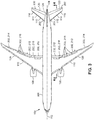
- the aircraft 100 is a tube-and-wing configuration having a fuselage 106 and a longitudinal axis 102 extending between the forward end and the aft end of the fuselage 106.
- the aircraft 100 may include one or more propulsion units 108 and one or more airfoils 110.
- the aft end of the fuselage 106 may include a vertical tail 124 and a horizontal tail.
- the horizontal tail may include a pair of horizontal stabilizers 114 ( Figure 3 ) symmetrically located on laterally opposite sides of an aircraft centerline 104 ( Figure 3 ) which may be coincident with the longitudinal axis 102.
- An elevator 120 may be pivotably coupled to each one of the horizontal stabilizers 114.
- the aircraft 100 may include a pair of wings 126, each of which may have a plurality of movable surfaces 202 symmetrically located on laterally opposite sides of the aircraft centerline 104.
- the wings 126 may each include movable surfaces 202 such as spoilers 218 laterally symmetrically located on opposite sides of the aircraft centerline 104.
- Each wing 126 may also include movable surfaces 202 such as flaps 212, ailerons 214, and/or flaperons 216 which may also be laterally symmetrically located on opposite sides of the aircraft centerline 104.
- the system 500 ( Figure 1 ) and method 700 ( Figure 19 ) is configured such that at least one laterally symmetric pair of movable surfaces 202 is deflected upon the generation of a command signal 512 ( Figure 1 ) from the flight control computer 502 ( Figure 1 ) in response to the flight control computer 502 determining the existence of icing conditions.
- system 500 Figure 1
- method 700 Figure 19
- system 500 and method 700 may be implemented in other airplane configurations including, but not limited to, a blended wing body configuration (not shown), a flying wing configuration (not shown), and any other one of a variety of aircraft configurations.
- the movable surfaces 202 for non-tube-and-wing airplane configurations may include elevons, canards, and/or other types of movable surfaces 202 laterally symmetrically located on opposite sides of the aircraft centerline 104, and capable of increasing the angle of attack of an airfoil 110 ( Figure 2 ) in response to a command signal 512 from a flight control computer 502 to temporarily increase the angle of attack of the airfoil 110 for purposes of shifting the water impingement limits 144, 146 ( Figures 5-6 ) of the airfoil 110.
- Figure 4 is a section view of wing 126 and a horizontal stabilizer 114 and elevator 120 of the aircraft 100 of Figure 3 .
- the wing 126 may include the above-mentioned movable surfaces 202 including flaps 212, ailerons 214, flaperons 216, and/or spoilers 218, each of which has a surface trailing edge 204.
- the horizontal stabilizer 114 and the elevator 120 may also be referred to as movable surfaces 202.
- the horizontal stabilizer 114 has a stabilizer leading edge 116, and the elevator 120 has an elevator trailing edge 122.
- the wing 126 is oriented at a wing angle of attack 128 and the horizontal stabilizer 114 is oriented at a stabilizer angle of attack 118.
- the angle of attack of an airfoil 110 is the angle between the chord line 112 of the airfoil 110 and the direction of the freestream flow 132 located immediately upstream of the airfoil 110.
- the chord line 112 of an airfoil 110 extends between the leading edge (e.g., wing leading edge 130) and the trailing edge (e.g., surface trailing edge 204) of the airfoil 110 when high-lift devices (e.g., flaps 212, leading edge slats - not shown) are retracted.
- the chord line 112 for the horizontal stabilizer 114 extends between the stabilizer leading edge 116 and the elevator trailing edge 122 when the elevator 120 is non-deflected.
- an airfoil 110 has a suction side 136 and a pressure side 138.
- the suction side 136 faces in the same direction as the direction of lift 140 generated by the airfoil 110
- the pressure side 138 faces in a direction opposite the direction of lift 140.
- the lift 140 is directed upwardly.
- the lift 140 may be directed downwardly to counteract a nose-down pitching moment caused by the upwardly directed lift 140 of the wings 126 acting aft of a center of gravity (not shown) of the aircraft 100.
- an increase in the angle of attack of an airfoil 110 causes the suction side 136 of the airfoil 110 to be angled more aftwardly or away from the direction of the oncoming freestream flow 132, and the pressure side 138 of the airfoil 110 to be angled more forwardly or toward the direction of the oncoming freestream flow 132.
- an increase in the wing angle of attack 128 results in the wing leading edge 130 being increasingly oriented in an upward direction.
- An increase in the stabilizer angle of attack 118 results in the stabilizer leading edge 116 being increasingly oriented in a downward direction.
- FIG. 5 shown in Figure 5 is a forward portion of a wing 126 oriented at a wing angle of attack 128 of 0°C.
- the suction side 136 has a suction side water impingement limit 144 and the pressure side 138 has a pressure side water impingement limit 146 which are each defined by the tangent trajectories 142 of water droplets 406 in the freestream flow 132.
- the suction side water impingement limit 144 and the pressure side water impingement limit 146 are each measured along the airfoil 110 surface relative to the highlight 134.
- the surface distance Ss is the distance between the highlight 134 and the suction side water impingement limit 144.
- the surface distance Sp is the distance between the highlight 134 and the pressure side water impingement limit 146.
- Figure 6 shows the forward portion of the wing 126 of Figure 5 oriented at an increased wing angle of attack 128 relative to Figure 5 .
- the increased wing angle of attack 128 in Figure 6 results in the tangent trajectories 142 of the water droplets 406 impinging at different locations on the wing leading edge 130 relative to the impingement locations in Figure 5 .
- the increased wing angle of attack 128 results in a combination lowering and forward shifting of the suction side water impingement limit 144, and a combination lowering and aftward shifting of the pressure side water impingement limit 146 relative to the location of the suction side water impingement limit 144 and pressure side water impingement limit 146 of Figure 5 .
- the surface distance Ss in Figure 6 is shorter than in Figure 5
- the surface distance Sp in Figure 6 is longer than in Figure 5 .
- Figure 7 shows the forward portion of the wing 126 of Figure 5 at a wing angle of attack 128 of 0° and illustrating the shape and size of ice accretion 148 forming on the wing leading edge 130.
- the ice accretion 148 forms between a suction side ice accretion limit 152 and a pressure side ice accretion limit 154, which respectively correspond to the location of the suction side water impingement limit 144 and pressure side water impingement limit 146 of Figure 5 .
- the ice accretion 148 has ice horns 150 that protrude into the freestream flow 132 and disrupt the air flowing over the airfoil 110.
- the ice accretion 148 with ice horns 150 in Figure 5 may result in a flow separation bubble (not shown) on the suction side 136 downstream of the leading edge, which may lower the angle of attack at which the wing 126 stalls (i.e., the stall angle 612 - Figure 9 ) relative to the stall angle 612 ( Figure 9 ) of the same wing 126 with no ice accretion.
- the ice accretion 148 may reduce the maximum lift coefficient 610 ( Figure 9 ) and generate aerodynamic drag.
- Figure 8 shows the wing 126 of Figure 7 at an increased angle of attack (i.e., in the upward direction), resulting in a downward shifting of the location of ice accretion 148 on the wing leading edge 130 relative to the ice accretion 148 in Figure 7 .
- the increased wing angle of attack 128 results in a combination lowering and forward shifting of the suction side ice accretion limit 152, and a combination lowering and aftward shifting of the pressure side ice accretion limit 154 relative to the location of the suction side ice accretion limit 152 and pressure side ice accretion limit 154 of Figure 7
- the combination lowering and forward shifting of the suction side ice accretion limit 152 and the combination lowering and aftward shifting of the pressure side ice accretion limit 154 may result in ice accretion 148 being located in a more favorable part of the pressure gradient along the surface of the wing leading edge 130, and/or may reduce the size of ice horns 150 or may avoid the formation of ice horns 150, which may reduce the disruption of air flowing over the wing 126.
- the pressure gradient occurs as a result of airflow over the curved surfaces of the wing
- Figure 9 is a graph 600 of coefficient of lift vs. angle of attack for the same airfoil 110 corresponding to three different states including: (1) a first state 602 in which the airfoil 110 is oriented at a relatively small angle of attack (e.g., 0°) and having ice accretion 148 due to exposure to icing conditions, (2) a second state 604 in which the airfoil 110 is oriented at a relatively large angle of attack and also having ice accretion 148 due to exposure to the same icing conditions as in the first state 602, and (3) a third state 608 in which the airfoil 110 is in a clean condition as a result of non-exposure to icing conditions.
- a first state 602 in which the airfoil 110 is oriented at a relatively small angle of attack (e.g., 0°) and having ice accretion 148 due to exposure to icing conditions
- a second state 604 in which the airfoil 110 is oriented
- the maximum lift coefficient 610 for the airfoil 110 in the second state 604 is lower than the maximum lift coefficient 610 for the airfoil 110 in the third state 608 due to the ice accretion 148 on the leading edge in the second state 604.
- the stall angle 612 for the airfoil 110 in the second state 604 is lower than the stall angle 612 of the airfoil 110 in the third state 608.
- the maximum lift coefficient 610 and the stall angle 612 for the airfoil 110 in the second state 604 is higher than the maximum lift coefficient 610 and stall angle 612 for the airfoil 110 in the first state 602 as a result of a lower location of ice accretion 148 on the leading edge of the airfoil 110 in the second state 604 relative to a higher location of ice accretion 148 on the leading edge of the airfoil 110 in the first state 602.
- the shift in the location of ice accretion 148 ( Figure 9 ) provided by the presently-disclosed system 500 ( Figure 1 ) and method 700 ( Figure 19 ) such as during cruise or holding of an aircraft ( Figure 2 ) allows for increased lift and a higher stall angle 612 ( Figure 9 ) at low airspeeds such as during approach.
- the relative increase in lift and stall angle 612 improves airplane performance by allowing for increased maximum landing weight for an equivalent approach speed or, conversely, a decreased approach speed for an equivalent maximum landing weight.
- the relative increase in lift and stall angle 612 allows for increased approach climb limit weights for an equivalent airspeed.
- the increased lift and stall angle 612 provided by the system 500 and method 700 also increases airplane safety by increasing the operating margin to stall.
- system 500 and method 700 reduces the need for ice protection hardware such as by reducing anti-ice requirements for an equivalent approach speed.
- the system 500 and method 700 simplifies the icing conditions certification process for determining critical ice accretion 148 ( Figure 9 ).
- the system 500 and method 700 increase airline service reliability by increasing the safety and efficiency to certify aircraft for operation in the most severe icing conditions such as the FAR Part 25, Appendix O, SLD (and foreign equivalents) icing conditions discussed above.
- Figure 10 is a section view of a wing 126 and a horizontal stabilizer 114 and elevator 120 in a baseline configuration of an aircraft 100 ( Figures 2-3 ).
- the wing 126 is oriented at a current angle of attack 304 (i.e., a wing angle of attack 128) of 0° relative to the freestream flow 132 direction which, in Figures 10 and 13 , is assumed to be parallel to the longitudinal axis 102 of the aircraft 100.
- the horizontal stabilizer 114 is oriented at a current angle of attack 304 (i.e., a stabilizer angle of attack 118) of 0° relative to the freestream flow 132 direction.
- the wing 126 is assumed to generate lift 140 in an upward direction and the horizontal stabilizer 114 is assumed to generate lift 140 in a downward direction in a manner maintaining trimmed, level flight.
- the flight control computer 502 receives data representative of the environmental parameters 402 (e.g., air temperature 404, droplet size 408, liquid water content 410) sensed in the environment 400 ( Figure 2 ) of the flight path 156 ( Figure 2 ) of an aircraft 100.
- the flight control computer 502 may determine, based at least on the environmental parameters 402 and optionally using the activation logic 504, the existence of icing conditions to which the aircraft 100 is currently subjected or is predicted to be subjected.
- the flight control computer 502 also generates, based on the determination of the existence of icing conditions, a command signal 512 for actuating at least one movable surface 202 of the aircraft 100 for increasing the angle of attack of an airfoil 110 ( Figure 2 ) in a manner modifying the water impingement limits 144, 146 ( Figures 5-6 ) of the airfoil 110.
- the flight control computer 502 is configured to receive data representative of a current angle of attack 304 of the airfoil 110 ( Figure 2 ), calculate, using angle of attack selection logic 506 of the flight control computer 502, a target angle of attack 508 ( Figure 2 ) of the airfoil 110 based on the icing conditions, and determine an angle of attack differential between the current angle of attack 304 ( Figure 10 ) and the target angle of attack 508 ( Figures 11-15 ).
- the flight control computer 502 is configured to generate a command signal 512 representative of the angle of attack differential.
- One or more surface actuators 200 are configured to receive the command signal 512 from the flight control computer 502, and adjust one or more movable surfaces 202 by an amount causing the angle of attack of the airfoil 110 to increase by an amount equal to the angle of attack differential to thereby bring the airfoil 110 into alignment with the target angle of attack 508 to thereby modify the water impingement limits 144, 146 ( Figures 5-6 ) on the airfoil 110.
- the flight control computer 502 is configured to calculate, using the angle of attack selection logic 506, the target angle of attack 508 based on the icing conditions and based on aircraft state data 300.
- Aircraft state data 300 may include the current airplane configuration such as flap position 312, speedbrake position 314, gear position 316 and thrust setting 318, and may also include airspeed 306, altitude 308, gross weight 310, location of the center of gravity (not shown) relative to the center of lift (not shown), and other aircraft state data 300.
- Flap position 312 data may include a flap setting such as on a flap control console (not shown) on a flight deck of an aircraft 100 ( Figure 2 ).
- the flap position 312 may include an up position (e.g., flaps fully retracted for cruise flight), a hold position, a climb or approach position, a takeoff or go-around position, and a landing position (e.g., flaps fully extended).
- An increasingly extended flap position 312 may increase the nose-down pitching moment of the aircraft 100, and may result in the flight control computer 502 compensating in the command signal 512 to cause increased deflection of the movable surfaces 202 to achieve the target angle of attack 508.
- Speedbrake position 314 refers to whether the spoilers 218 (e.g., flight spoilers - Figure 3 ) are retracted or deployed and, if deployed, the angle of deployment. Spoilers 218 that are partially deployed may increase the nose-down pitching moment and may result in the flight control computer 502 compensating in the command signal 512 to cause increased deflection of the movable surfaces 202 to achieve the target angle of attack 508.
- Gear position 316 refers to whether the landing gear (not shown) is up or down.
- Landing gear in the down position generates increased aerodynamic drag and a nose-down pitching moment due to the location of the aerodynamic drag underneath the wings 126 ( Figure 2 ), and may result in the flight control computer 502 compensating in the command signal 512 to cause increased deflection of the movable surfaces 202 to achieve the target angle of attack 508.
- an increased thrust setting 318 may generate a nose-up pitching moment causing the flight control computer 502 to generate a command signal 512 in a manner causing reduced deflection of the movable surfaces 202 to achieve the target angle of attack 508.
- Increased airspeed 306 may increase the rate of ice accretion 148 ( Figure 7-8 ) and may correspond to increased severity of icing conditions, resulting in the flight control computer 502 compensating in the command signal 512 by commanding increased deflection of the movable surfaces 202 to achieve a higher target angle of attack 508 than for less severe icing conditions.
- the flight control computer 502 may also factor in the altitude 308, gross weight 310, and/or location of the center of gravity (not shown) in determining the command signal 512 required for deflecting the movable surfaces 202 in a manner for achieving the target angle of attack 508.
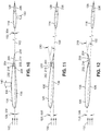
- Figure 11 illustrates an example in which the flight control computer 502 ( Figure 1 ) generates one or more command signals 512 ( Figure 1 ) causing one or more surface actuators 200 ( Figure 1 ) to upwardly deflect the surface trailing edges 204 of at least one laterally symmetric pair of movable surfaces 202 respectively coupled to the pair of wings 126.
- the flight control computer 502 may generate command signals 512 causing the deflection of at least one laterally symmetric pair of flaps 212 ( Figure 3 ), ailerons 214, and/or spoilers 218.
- one or more laterally symmetric pair of other types of movable surfaces 202 may be deflected to cause an increase in the angle of attack of an airfoil 110.
- the present disclosure contemplates deflecting any type of movable surface 202 mounted anywhere on the aircraft 100, and is not limited to deflecting flaps 212, spoilers 218, and/or ailerons 214.
- Figure 11 shows the upward deflection of at least one laterally symmetric pair ( Figure 3 ) of spoilers 218 from an original position 206 ( Figure 10 ) through a deflection angle 210 ( Figure 11 ) to an adjusted position 208 ( Figure 11 ).
- upward deflection of a movable surface 202 refers to the surface trailing edge 204 moving upwardly.
- Movable surfaces 202 may be deflected through relatively small deflection angles 210 such as from approximately 0.5-4°, depending upon the severity of the icing conditions and the aircraft state.
- the flight control computer 502 may calculate deflection angles 210 that are less than 0.5°, and/or the flight control computer 502 may generate command signals 512 for deflecting a single laterally symmetric pair of movable surfaces 202.
- the flight control computer 502 may calculate deflection angles 210 that are larger than 4°, and/or the flight control computer 502 may generate command signals 512 for deflecting multiple laterally symmetric pairs of movable surfaces 202.
- the deflection of the spoilers 218 causes an upward increase in the wing angle of attack 128 wherein the wing 126 moves from a current angle of attack 304 ( Figure 10 ) to a target angle of attack 508 ( Figure 11 ) calculated by the flight control computer 502.
- the increase in the wing angle of attack 128 causes the above-described combination of lowering and forward shifting of the suction side water impingement limit 144 and corresponding combination of lowering and aftward shifting of the pressure side water impingement limit 146, as illustrated in Figures 5-6 .
- Figure 12 represents the upward deflection of at least one laterally symmetric pair of ailerons 214 from an original position 206 ( Figure 10 ) through a deflection angle 210 to an adjusted position 208.
- the upward deflection of the laterally symmetric pair of ailerons 214 causes the wing angle of attack 128 to increase from the current angle of attack 304 ( Figure 10 ) to the target angle of attack 508.
- the increase in the wing angle of attack 28 increases the pitch angle (not shown) of the aircraft 100.
- the horizontal stabilizer 114 and elevator 120 in Figures 11-12 are at the same orientation relative to the longitudinal axis 102 as in Figure 10 .
- Figure 13 illustrates an example in which the flight control computer 502 ( Figure 1 ) is configured to generate one or more command signals 512 ( Figure 1 ) causing one or more surface actuators 200 ( Figure 1 ) to downwardly deflect the stabilizer leading edge 116 of the pair ( Figure 3 ) of horizontal stabilizers 114, and downwardly deflect the elevator trailing edge 122 of the elevator 120 (relative to the chord line 112 of the horizontal stabilizer 114) pivotably coupled to each one of the horizontal stabilizers 114.
- the flight control computer 502 Figure 1
- Figure 1 is configured to generate one or more command signals 512 ( Figure 1 ) causing one or more surface actuators 200 ( Figure 1 ) to downwardly deflect the stabilizer leading edge 116 of the pair ( Figure 3 ) of horizontal stabilizers 114, and downwardly deflect the elevator trailing edge 122 of the elevator 120 (relative to the chord line 112 of the horizontal stabilizer 114) pivotably coupled to each one of the horizontal stabilizers 114.
- the downward deflection of the stabilizer leading edge 116 causes the stabilizer angle of attack 118 to increase (i.e., relative to the freestream flow 132 direction) in a downward direction from the current angle of attack 304 ( Figure 10 ) to the target angle of attack 508 ( Figure 13 ) as calculated by the flight control computer 502.
- increasing the stabilizer angle of attack 118 in a downward direction causes a combination raising and forward shifting of a suction side water impingement limit 144 (not shown) on the suction side 136 (i.e., on the lower surface) of the horizontal stabilizer 114, and a corresponding combination of lowering and aftward shifting of the pressure side water impingement limit 146 (not shown) on the pressure side 138 (i.e., on the upper surface) of the horizontal stabilizer 114.
- the shifting of the suction side water impingement limit 144 and pressure side water impingement limit 146 on the stabilizer leading edge 116 shifts the location of ice accretion 148 (not shown) on the stabilizer leading edge 116, which reduces aerodynamic drag and reduces the extent of disruption of airflow over the horizontal tail (i.e., the horizontal stabilizer 114 and elevator 120) to thereby improve the ability of the horizontal tail to generate a downward force (e.g., lift 140 - Figure 10 ) for counteracting the nose-down pitching moment of the wings 126.
- a downward force e.g., lift 140 - Figure 10
- the elevator trailing edge 122 may be downwardly deflected in a manner resulting in a downward increase in the stabilizer angle of attack 118 without changing the wing angle of attack 128.
- the flight control computer 502 ( Figure 1 ) may generate command signals 512 causing the elevator trailing edge 122 to be downwardly deflected from an original position 206 ( Figure 10 ) through a deflection angle 210 to an adjusted position 208 that maintains the wing 126 at substantially (e.g., within 10 percent) the same wing angle of attack 128 as prior to the adjustment of the horizontal stabilizer 114 and elevator 120.
- the flight control computer 502 may generate command signals and 512 to adjust the orientation of the horizontal stabilizer 114 and elevator 120 in a manner maintaining the altitude 308 ( Figure 1 ) of the aircraft 100.
- the flight control computer 502 may increase a thrust setting 318 ( Figure 1 ) of one or more propulsion units 108 ( Figure 3 ) of the aircraft 100 in a manner maintaining the aircraft 100 at an airspeed 306 ( Figure 1 ) and/or an altitude 308 that is substantially equivalent (e.g., within 20 percent) to the airspeed 306 and altitude 308 of the aircraft 100 prior to adjusting one or more movable surfaces 202 (e.g., flaps 212, ailerons 214, flaperons 216, spoilers 218, horizontal stabilizers 114, elevators 120, etc.) and increasing the angle of attack of one or more airfoils 110 (e.g., wings 126, horizontal stabilizers 114) for purposes of modifying the water impingement limits 144, 146
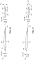
- Figure 14 illustrates an example in which the flight control computer 502 ( Figure 1 ) generates one or more command signals 512 ( Figure 1 ) causing one or more surface actuators 200 ( Figure 1 ) to downwardly deflect the stabilizer leading edge 116 and downwardly deflect the elevator trailing edge 122 of the elevator 120 similar to that described above in Figure 13 , while causing other surface actuators 200 ( Figure 1 ) to upwardly deflect at least one laterally symmetric pair of movable surfaces 202 respectively coupled to the pair of wings 126 in a manner increasing the stabilizer angle of attack 118 in a downward direction (relative to the freestream flow 132 direction) and increasing the wing angle of attack 128 in an upward direction (relative to the freestream flow 132 direction).
- Figure 14 illustrates the downward deflection of the horizontal stabilizer 114 and the downward deflection of the elevator 120 with simultaneous upward deflection of the surface trailing edge 204 of a spoiler 218 from an original position 206 ( Figure 13 ) through a deflection angle 210 to an adjusted position 208, resulting in a downward increase in the stabilizer angle of attack 118 and an upward increase in the wing angle of attack 128.
- the downward increase in the stabilizer angle of attack 118 and the upward increase in the wing angle of attack 128 each modifies the water impingement limits 144, 146 ( Figures 5-6 ) on the stabilizer leading edge 116 and wing leading edge 130 which advantageously reduces the effects of ice accretion 148 (e.g., Figure 7-8 ) on air flow over the horizontal stabilizers 114 and wings 126.
- Figure 15 illustrates the downward deflection of the horizontal stabilizer 114 and the downward deflection of the elevator 120 with simultaneous upward deflection of the surface trailing edge 204 of an aileron 214 to achieve a downward increase in the stabilizer angle of attack 118 (relative to the freestream flow 132 direction) and an upward increase in the wing angle of attack 128 (relative to the freestream flow 132 direction).
- the downward increase in the stabilizer angle of attack 118 and the upward increase in the wing angle of attack 128 modifies the water impingement limits 144, 146 ( Figures 5-6 ) on the stabilizer leading edge 116 and wing leading edge 130.
- Figure 16 illustrates an example in which the flight control computer 502 ( Figure 1 ) generates one or more command signals 512 ( Figure 1 ) causing one or more surface actuators 200 ( Figure 1 ) to upwardly deflect the stabilizer leading edge 116 and upwardly deflect the elevator trailing edge 122 in a manner resulting in an upward increase in the stabilizer angle of attack 118.
- the upward increase in the stabilizer angle of attack 118 biases the water impingement limits 144, 146 (not shown) on the horizontal stabilizer 114 more toward the suction side 136, and is therefore more adverse for the ice accretion limits 152, 154 (not shown) on the horizontal stabilizer 114.
- upwardly increasing the stabilizer angle of attack 118 may be advantageous for aircraft 100 ( Figure 16 ) that have a reduced amount of elevator 120 authority in the nose-down direction in icing conditions.
- the horizontal tail may maintain the aircraft 100 in trimmed flight while maintaining nose-down authority of the elevator 120 (e.g., to meet certification requirements).
- Figure 17 illustrates an example similar to Figure 16 in which the flight control computer 502 ( Figure 1 ) generates one or more command signals 512 ( Figure 1 ) causing surface actuators 200 ( Figure 1 ) to upwardly deflect the stabilizer leading edge 116 and upwardly deflect the elevator trailing edge 122 by an amount resulting in an upward increase in the wing angle of attack 128 in addition to the upward increase in the stabilizer angle of attack 118.
- the upward increase in the wing angle of attack 128 improves the water impingement limits 144, 146 ( Figures 5-6 ) on the wing leading edge 130 in a manner as described above.
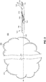
- Figure 18 shows an aircraft 100 on a flight path 156 through a cloud 412 containing icing conditions.
- Figure 18 illustrates a temporary increase in the wing angle of attack 128 (shown exaggerated) as the aircraft 100 passes through the cloud 412 while maintaining the same altitude 308 ( Figure 1 ) as prior to entering the cloud 412.
- temporarily increasing the wing angle of attack 128 of the aircraft 100 modifies the water impingement limits 144, 146 ( Figures 5-6 ) on the wing leading edges 130 ( Figures 5-6 ) which advantageously reduce the effects of ice accretion 148, as shown in the graph of Figure 9 .
- the flight control computer 502 may continuously monitor the environmental parameters 402 ( Figure 1 ) to determine whether icing conditions continue to exist. Upon determining that icing conditions no longer exist, the flight control computer 502 may autonomously (i.e., without human intervention) command the movable surfaces 202 ( Figure 1 ) from the adjusted position 208 ( Figure 11 ) back to the original position 206 ( Figure 10 ). Alternatively or additionally, the flight control computer 502 may at any time allow pilot input 514 ( Figure 1 ) for commanding the movable surfaces 202 ( Figure 1 ) to move from the adjusted position 208 back to the original position 206.
- Step 702 of the method 700 includes sensing environmental parameters 402 in the environment 400 of the flight path 156 of an aircraft 100.
- the environmental parameters 402 may include air temperature 404 and droplet size 408 of water dropped.
- the environmental parameters 402 may also liquid water content 410, altitude 308, horizontal extent and/or vertical extent of icing conditions, and other environmental parameters 402.
- Step 702 may also include sensing the aircraft surface temperatures 302 to determine the existence of icing additions if aircraft surface temperatures 302 are below 0°C, as described above.
- Step 704 of the method 700 includes determining, based on the environmental parameters 402, the existence of icing conditions.
- the step of determining the existence of icing conditions may include determining the current existence of icing conditions, or determining the existence of icing conditions to which the aircraft 100 is predicted to be subjected at a later point along the flight path 156 of the aircraft 100.
- the existence of icing conditions may be determined by ground-based or airborne weather measurement instrumentation.
- the determination of icing conditions may also be based on reports of icing conditions by pilots of other aircraft in areas near the flight path 156.
- Step 706 of the method 700 includes adjusting, in response to determining the existence of icing conditions, at least one movable surface 202 of the aircraft 100.
- the movable surface 202 may be moved from an original position 206 through a deflection angle 210 to an adjusted position 208.
- the original position 206 of a movable surface 202 is the position immediately prior to changing the orientation of the movable surface 202 to achieve the target angle of attack 508 of an airfoil 110.
- Step 708 of the method 700 includes increasing the angle of attack of an airfoil 110 (e.g., the wings 126, the horizontal stabilizers 114) in response to adjusting the movable surface 202 to thereby cause a modification of the water impingement limit 144, 146 on the airfoil 110.
- an increase in the wing angle of attack 128 causes a combination lowering and forward shifting of a suction side water impingement limit 144 on the suction side 136 (i.e., the upper surface) of the wings 126 and a combination lowering and aftward shifting of the pressure side water impingement limit 146 on the pressure side 138 (i.e., the lower surface) of the wings 126.
- the method 700 may include determining a current angle of attack 304 of the airfoil 110, calculating a target angle of attack 508 of the airfoil 110 based on the icing conditions, and determining an angle of attack differential between the current angle of attack 304 and the target angle of attack 508.
- step 706 may include adjusting at least one movable surface 202 by an amount causing the angle of attack of the airfoil 110 to increase by an amount equal to the angle of attack differential to thereby bring the airfoil 110 into alignment with the target angle of attack 508, as described above.
- the step of calculating the target angle of attack 508 may include calculating the target angle of attack 508 based on the icing conditions and based on aircraft state data 300 such as current flap position 312, speedbrake position 314, airspeed 306, altitude 308, thrust setting 318, gear position 316, and/or other aircraft state data 300, as described above.
- step 704 of determining the existence of icing conditions may include determining the severity of the icing conditions based at least on air temperature 404 and droplet size 408 of water droplets 406 in the environment 400 of the aircraft 100. As mentioned above, the lower the air temperature 404 and/or the larger the droplet size 408, the more severe the icing condition.
- step of calculating the target angle of attack 508 may be based on the severity of icing conditions. For example, the more severe the icing addition, the larger the target angle of attack 508 of the airfoil 110.
- step 706 may comprise adjusting the movable surface 202 by an amount proportional to the severity of the icing conditions.
- the step 706 of adjusting the movable surface 202 may comprise upwardly deflecting a surface trailing edge 204 of at least one laterally symmetric pair of movable surfaces 202 respectively coupled to a pair of wings 126 respectively located on laterally opposite sides of the aircraft centerline 104.
- upwardly deflecting a laterally symmetric pair of movable surfaces 202 may include upwardly deflecting a surface trailing edge 204 of a laterally symmetric pair of flaps 212, spoilers 218, and/or ailerons 214.
- step 708 of increasing the angle of attack of the airfoil 110 may comprise increasing the wing angle of attack 128 in response to upwardly deflecting the laterally symmetric pair of flaps 212, spoilers 218, and/or ailerons 214.
- the step 706 of adjusting the movable surface 202 may comprise downwardly deflecting a stabilizer leading edge 116 of a horizontal stabilizer 114 and downwardly deflecting an elevator trailing edge 122 of an elevator 120 such that the stabilizer leading edge 116 of the horizontal stabilizer 114 moves downwardly and the elevator trailing edge 122 of the elevator 120 moves downwardly as shown in Figures 13-15 .
- step 708 of increasing the angle of attack of the airfoil 110 comprises increasing the stabilizer angle of attack 118 in a downward direction in response to downwardly deflecting the stabilizer leading edge 116.
- the downward deflection of the stabilizer leading edge 116 and downward deflection of the elevator trailing edge 122 may be performed in a manner such that the wing angle of attack 128 remains unchanged.
- increasing the stabilizer angle of attack 118 in the downward direction may cause a combination raising and forward shifting of a suction side water impingement limit 144 (not shown) on the suction side 136 (e.g., the lower surface) of the horizontal stabilizer 114 and correspondingly a combination lowering and aftward shifting of the pressure side water impingement limit 146 (not shown) on the pressure side 138 (e.g., the upper surface) of the horizontal stabilizer 114.
- the step 706 of adjusting the movable surface 202 may comprise downwardly deflecting the stabilizer leading edge 116 and downwardly deflecting the elevator trailing edge 122 while upwardly deflecting a surface trailing edge 204 of at least one laterally symmetric pair of movable surfaces 202 respectively coupled to a pair of wings 126 respectively located on laterally opposite sides of the aircraft 100.
- Figures 14-15 illustrate the downward deflection of the stabilizer leading edge 116 and the downward deflection of the elevator trailing edge 122 with simultaneous upward deflection of at least one laterally symmetric pair of spoilers 218 ( Figure 14 ) and/or ailerons 214 ( Figure 15 ).
- step 708 of increasing the angle of attack of the airfoil 110 comprises increasing the stabilizer angle of attack 118 in a downward direction and increasing the wing angle of attack 128 in an upward direction in response to downwardly deflecting the horizontal stabilizer 114 and downwardly deflecting the elevator 120 and upwardly deflecting at least one laterally symmetric pair of movable surfaces 202 (e.g., spoilers 218, ailerons 214, flaps 212, flaperons 216, etc.) of the wings 126.
- movable surfaces 202 e.g., spoilers 218, ailerons 214, flaps 212, flaperons 216, etc.
- the step 706 of adjusting the movable surface 202 may comprise upwardly deflecting the stabilizer leading edge 116 of the horizontal stabilizer 114 and upwardly deflecting the elevator trailing edge of the elevator 120.
- Figure 16 illustrates the upward deflection of the stabilizer leading edge 116 and the upward deflection of the elevator trailing edge 122.
- step 708 of increasing the angle of attack of the airfoil 110 comprises increasing the stabilizer angle of attack 118 in an upward direction in response to upwardly deflecting the stabilizer leading edge 116 to thereby maintain nose-down authority of the elevator 120 in icing conditions with ice accretion (not shown) on the horizontal stabilizer 114, as described above.
- Figure 17 illustrates an example similar to Figure 16 , with the exception that the stabilizer leading edge 116 and the elevator trailing edge 122 in Figure 17 are both deflected upwardly by an amount to increase the wing angle of attack 128 in an upward direction to thereby improve the water impingement limits 144, 146 ( Figures 5-6 ) on the wing leading edge 130. Similar to the example of Figure 16 , the horizontal stabilizer 114 and the elevator 120 in Figure 17 may be deflected upwardly in a manner maintaining the aircraft 100 in trimmed flight while retaining nose-down authority of the elevator 120 in icing conditions.
- the method 700 may further comprise increasing the thrust setting 318 of one or more propulsion units 108 ( Figure 3 ) of the aircraft 100 in a manner maintaining the airspeed 306 and/or the altitude 308 of the aircraft 100 to be substantially (e.g., within 20 percent) equivalent to the airspeed 306 and the altitude 308 of the aircraft 100 prior to adjusting the one or more movable surfaces 202 for increasing the angle of attack of one or more airfoils 110.
- the method 700 may optionally include continuously monitoring the environmental parameters 402 to determine whether icing conditions continue to exist, and autonomously commanding the one or more movable surface 202 to move back to the original position 206 of the movable surfaces 202 when icing conditions cease to exist.
- the autonomous commanding may be performed by a flight control computer 502 upon determining that icing conditions no longer exist.
- Figure 18 illustrates an example of an aircraft 100 on a flight path 156 that passes through a cloud 412 containing icing conditions.
- the wings 126 Prior to entering the cloud 412, the wings 126 are oriented at a current angle of attack 304.
- one or more movable surfaces 202 Prior to or immediately upon entering the cloud 412, one or more movable surfaces 202 ( Figure 11 ) may be autonomously or manually commanded to be deflected in a manner causing the wing angle of attack 128 to increase from the current angle of attack 304 to a target angle of attack 508.
- Autonomous commanding of the movable surfaces 202 may be performed by the activation logic 504 ( Figure 1 ) of a flight control computer 502 ( Figure 1 ) upon determining the existence of icing conditions.
- Manual commanding of the movable surfaces 202 may be performed by pilot input 514 ( Figure 1 ) in which a member of the flight crew initiates the activation logic 504 ( Figure 1 ) of the flight control computer 502.
- a pilot or other flight crew member may determine the existence of icing conditions by visually observing water drops on the aircraft surfaces, in combination with the pilot or flight crew member determining that the air temperature 404 (e.g., the outside air temperature) and/or the aircraft surface temperature 302 (e.g., of the wings 126) are at or below 0°C.
- the wings 126 may be maintained at a target angle of attack 508 while the aircraft 100 is subjected to the icing additions (e.g., within the cloud 412).
- the movable surfaces 202 may be autonomously or manually commanded to return to their original position 206, causing the wing 126 to be reoriented back to the same angle of attack as prior to entering the icing conditions.
- the aircraft 100 may be maintained at the same altitude 308 by temporarily adjusting (e.g., increasing) the thrust setting 318 ( Figure 1 ) of the propulsion units 108 to compensate for the increased aerodynamic drag generated by the temporary deflection of the movable surfaces 202 ( Figure 11 ) and/or by the increase in the angle of attack of the airfoils the wings 126 for the time period when the aircraft 100 is subjected to the icing conditions.
- temporarily adjusting e.g., increasing
- the thrust setting 318 ( Figure 1 ) of the propulsion units 108 to compensate for the increased aerodynamic drag generated by the temporary deflection of the movable surfaces 202 ( Figure 11 ) and/or by the increase in the angle of attack of the airfoils the wings 126 for the time period when the aircraft 100 is subjected to the icing conditions.
Landscapes
- Engineering & Computer Science (AREA)
- Aviation & Aerospace Engineering (AREA)
- Automation & Control Theory (AREA)
- Radar, Positioning & Navigation (AREA)
- Remote Sensing (AREA)
- Physics & Mathematics (AREA)
- General Physics & Mathematics (AREA)
- Aerodynamic Tests, Hydrodynamic Tests, Wind Tunnels, And Water Tanks (AREA)
Abstract
Description
- The present disclosure relates generally to aircraft flight operations and, more particularly, to a system and method for modifying the water impingement limits on an airfoil of an aircraft.
- Ice can form on the surfaces of an aircraft in flight when water droplets impinge and freeze on the aircraft surfaces. The accretion of ice on certain aerodynamic surfaces can reduce the performance and handling characteristics of the aircraft. For example, ice accretion on the leading edges of the wings can alter the cross-sectional shape of the wings which can disrupt the flow of air over the wings, resulting in reduced lift capability of the wings, increased aerodynamic drag, added weight, and increased stall speed of the aircraft.
- Current methods of addressing ice accretion on the leading edges of airfoils include the use of inflatable deicing boots mounted on leading edge surfaces. When ice has accumulated on a leading edge, the boots may be inflated with compressed air causing the ice to crack. Air flowing over the wings blows the ice off the wings, after which the boots are deflated to return the leading edge to its pre-inflated shape. Although generally effective, deicing boots add cost, complexity and weight to the aircraft.
- Another method of addressing ice accretion on leading edges involves the use of a bleed air de-icing or anti-icing system in which hot air is bled from gas turbine engines of an aircraft. The bleed air is routed through spray tubes extending along the interior of the leading edges and is discharged in a manner to heat the wing surfaces. The bleed air may be periodically activated in a manner to maintain the surfaces of the leading edges above freezing to prevent the formation of ice, or to melt the ice to an extent that air flowing over the wings blows the ice off the wings. Although effective in addressing ice accretion, the extraction of bleed air from the engines reduces engine performance. In addition, the spray tubes and other hardware of a bleed air system add to the cost, complexity and weight of the aircraft.
- As can be seen, there exists a need in the art for a system and method for reducing ice accretion on an airfoil that reduces the need for ice protection hardware (e.g., deicing or anti-icing system hardware).
- The above-noted needs associated with ice accretion on airfoils are specifically addressed and alleviated by the present disclosure which provides a system for modifying a location of a water impingement limit on an airfoil of an aircraft. The system includes a flight control computer configured to receive data representative of environmental parameters in an environment of a flight path of an aircraft. In addition, the flight control computer is configured to determine, based on the environmental parameters, an existence of icing conditions to which the aircraft is currently subjected or is predicted to be subjected. Furthermore, the flight control computer is configured to generate, based on the existence of icing conditions, a command signal for actuating a movable surface of the aircraft. The system further includes a surface actuator configured to receive the command signal from the flight control computer and adjust the movable surface in a manner causing an increase in an angle of attack of the airfoil to thereby modify a water impingement limit on the airfoil.
- Also disclosed is a method of modifying a location of a water impingement limit on a surface of an airfoil of an aircraft. The method includes sensing environmental parameters in an environment of a flight path of an aircraft, and determining, based on the environmental parameters, an existence of icing conditions to which the aircraft is currently subjected or is predicted to be subjected. In addition, the method includes adjusting, in response to determining the existence of icing conditions, at least one movable surface of the aircraft, and increasing an angle of attack of the airfoil in response to adjusting the movable surface to thereby cause a modification of a water impingement limit on the airfoil.
- A further example of the method includes sensing an air temperature and a droplet size of water droplets in an environment of a flight path of the aircraft, determining, based on the air temperature and the droplet size, an existence of icing conditions to which the aircraft is currently subjected or is predicted to be subjected, and upwardly deflecting, in response to determining the existence of icing conditions, at least one laterally symmetric pair of movable surfaces respectively coupled to the pair of wings. In addition, the method includes increasing a wing angle of attack of the wings in response to upwardly deflecting the laterally symmetric pair of movable surfaces to thereby cause a forward and downward shift of a water impingement upper limit on an upper surface of the wings and an aftward and downward shift of a water impingement lower limit on a lower surface of the wings.
- The features, functions and advantages that have been discussed can be achieved independently in various examples of the present disclosure or may be combined in yet other examples, further details of which can be seen with reference to the following description and drawings below.
- These and other features of the present disclosure will become more apparent upon reference to the drawings wherein like numbers refer to like parts throughout and wherein:
-
Figure 1 is a schematic diagram of a system for modifying the water impingement limits on an airfoil; -
Figure 2 is an illustration of an aircraft on a flight path toward a cloud containing icing conditions; -
Figure 3 is a top view of an aircraft having movable surfaces that are adjustable using the presently-disclosed system for increasing the angle of attack of one or more airfoils of the aircraft to thereby cause a modification of the water impingement limit of the airfoils; -
Figure 4 is a section view taken along line 4 ofFigure 3 and illustrating a wing and a horizontal stabilizer oriented respectively at a wing angle of attack and a stabilizer angle of attack; -
Figure 5 is a side view of a forward portion of a wing oriented at an angle of attack of 0° and illustrating the location of a suction side water impingement limit on the suction side (e.g., upper side) of the wing and a pressure side water impingement limit on the pressure side (e.g., lower side) of the wing as defined by the tangent trajectories of water droplets entrained in a freestream flow through which the airfoil is moving; -
Figure 6 is a side view of the forward portion of the wing ofFigure 5 oriented at an increased angle of attack and resulting in a combination lowering and forward shifting of the suction side water impingement limit and a combination lowering and aftward shifting of the pressure side water impingement limit relative to the corresponding water impingement limits ofFigure 5 ; -
Figure 7 is a side view of a forward portion of a wing oriented at an angle of attack of 0° and illustrating ice accretion on the wing leading edge; -
Figure 8 is a side view of a forward portion of the wing ofFigure 7 oriented at an increased angle of attack and resulting in a downward shifting of the location of ice accretion on the wing leading edge relative to the ice accretion inFigure 7 ; -
Figure 9 is a graph of coefficient of lift vs. angle of attack for the same airfoil in three different states including: (1) increased ice accretion resulting from water impingement limits associated with a relatively small angle of attack (e.g., 0°), (2) reduced ice accretion resulting from water impingement limits associated with a relatively larger angle of attack, and (3) a clean condition without ice accretion; -
Figure 10 is a section view of a wing and a horizontal stabilizer oriented respectively at a wing angle of attack of 0° and a stabilizer angle of attack of 0°; -
Figure 11 is a section view of the wing and horizontal stabilizer ofFigure 10 showing the upward deflection of a spoiler causing an upward increase in the wing angle of attack of the wings to thereby cause a modification of the water impingement limits on the wings; -
Figure 12 is a section view of the wing and horizontal stabilizer and elevator ofFigure 10 showing the upward deflection of an aileron causing an upward increase in the wing angle of attack; -
Figure 13 is a section view of the wing and horizontal stabilizer and elevator ofFigure 10 showing the downward deflection of the stabilizer leading edge of the horizontal stabilizer and the downward deflection of the elevator trailing edge of the elevator in a manner resulting in a downward increase in the stabilizer angle of attack without changing the wing angle of attack; -
Figure 14 is a section view of the wing and horizontal stabilizer and elevator ofFigure 10 showing the downward deflection of the horizontal stabilizer and the downward deflection of the elevator with simultaneous upward deflection of the surface trailing edge of the spoiler in a manner resulting in a downward increase in the stabilizer angle of attack and an upward increase in the wing angle of attack; -
Figure 15 is a section view of the wing and horizontal stabilizer and elevator ofFigure 10 showing the downward deflection of the horizontal stabilizer and the downward deflection of the elevator with simultaneous upward deflection of the surface trailing edge of the aileron in a manner resulting in a downward increase in the stabilizer angle of attack and an upward increase in the wing angle of attack; -
Figure 16 is a section view of the wing and horizontal stabilizer and elevator ofFigure 10 showing the upward deflection of the horizontal stabilizer and the upward deflection of the elevator resulting in the stabilizer angle of attack being oriented in an upward direction in a manner maintaining nose-down authority of the elevator in icing conditions; -
Figure 17 is a section view of the wing and horizontal stabilizer and elevator ofFigure 16 showing increased upward deflection of the elevator causing an upward increase in the wing angle of attack along with the upward deflection of the horizontal stabilizer in a manner maintaining nose-down authority of the elevator; -
Figure 18 is an illustration of an aircraft on a flight path through a cloud containing icing conditions and showing a temporary increase in the wing angle of attack while the aircraft passes through the cloud while maintaining the altitude of the aircraft; and -
Figure 19 is a flow chart of operations included in a method of modifying the location of the water impingement limits on an airfoil. - Referring now to the drawings wherein the showings are for purposes of illustrating preferred and various examples of the disclosure, shown in
Figure 1 is a schematic diagram of a water impingementlimit modification system 500 for modifying the location of thewater impingement limits 144, 146 (Figures 5-6 ) on at least one airfoil 110 (Figure 2 ) of an aircraft 100 (Figure 2 ). Modification of the location of thewater impingement limits airfoil 110 results in the modification of the location ofice accretion limits 152, 154 (Figures 7-8 ) on theairfoil 110. Modifying the location of theice accretion limits ice accretion 148 on the aerodynamics of air flowing over theairfoil 110. For example, modifying the location of theice accretion limits airfoil 110 that may occur as a result of theice accretion 148. In addition, modifying the location of theice accretion limits ice accretion 148 on the maximum lift coefficient 610 (e.g.,Figure 9 ), and reduces the amount of aerodynamic drag generated by theice accretion 148. - As described in greater detail below, the water impingement limits 144, 146 on an
airfoil 110 are the locations defined by the tangent trajectories 142 (Figures 5-6 ) of water droplets 406 (Figures 4-6 ), in the flow of air moving over theairfoil 110. For example, referring toFigure 5 , shown is a forward portion orwing leading edge 130 of awing 126 which has a suction side 136 (i.e., a wing upper surface having a relatively high degree of curvature, the side of lower pressure side), and a pressure side 138 (i.e., awing 126 lower surface having a relatively low degree of curvature, the side of higher pressure). Thesuction side 136 has a suction sidewater impingement limit 144 and thepressure side 138 has a pressure sidewater impingement limit 146 which are each measured along theairfoil 110 surface relative to thehighlight 134 of theairfoil 110. In the present disclosure, thehighlight 134 of anairfoil 110 is the point furthest forward on the surface of the leading edge when theairfoil 110 is at an angle of attack of 0°. Forairfoils 110 having a symmetrical cross-section such as some horizontal tails (e.g., ahorizontal stabilizer 114 and elevator 120 -Figures 3-4 ), thesuction side 136 and thepressure side 138 may have the same degree of curvature. However, orienting the horizontal tail at an angle of attack in which thestabilizer leading edge 116 is oriented in a downward direction generates low pressure or suction on the stabilizer lower side such that the stabilizer lower side is the suction side 136 (i.e., the side of lower pressure side) and the stabilizer upper side is the pressure side 138 (i.e., the side of higher pressure side). Regardless of whether thesuction side 136 of anairfoil 110 is on the upper side or the lower side of theairfoil 110, the suction sidewater impingement limit 144 and the pressure sidewater impingement limit 146 of anairfoil 110 are each located at a respective tangent trajectory 142 (Figures 5-6 ) of a water droplet 406 (Figures 4-6 ) of a given size that starts out upstream of theairfoil 110 in the freestream flow 132 (e.g.,Figures 4-7 ), as described in greater detail below. - When an aircraft 100 (
Figure 2 ) is subjected to icing conditions, water droplets 406 (Figures 2 and4-6 ) impinging on the airfoil 110 (e.g., between the suction sidewater impingement limit 144 and the pressure side water impingement limit 146 -Figures 5-6 ) will freeze, causing ice accretion 148 (Figure 7 ) on theairfoil 110. Advantageously, in the presently-disclosed system 500 (Figure 1 ), thesystem 500 is configured to detect the existence of icing conditions such that when theaircraft 100 encounters or is predicted to encounter icing conditions, thesystem 500 is configured to increase the angle of attack (Figure 6 ) of at least oneairfoil 110 of theaircraft 100 in a manner causing the location of thewater impingement limits 144, 146 (Figures 5-6 ) to proactively shift at least partially away from the suction side 136 (Figures 5-6 ), and shift more toward the pressure side 138 (Figures 5-6 ). In the example of thewing 126 ofFigures 5-6 , an increase in the wing angle ofattack 128 causes a combination lowering and forward shifting of the suction sidewater impingement limit 144 relative to thehighlight 134, and a combination lowering and aftward shifting of the pressure sidewater impingement limit 146 relative to thehighlight 134. Correspondingly inFigures 7-8 , the shifting of thewater impingement limits 144, 146 (Figures 5-6 ) has the effect of shifting the location of theice accretion limits 152, 154 (Figures 7-8 ) at least partially away from the suction side 136 (i.e., area of high curvature) of thewing 126, which reduces the above-mentioned negative effects ofice accretion 148 on the aerodynamics of thewing 126. - Referring again to
Figure 1 , thesystem 500 includes a flight control computer 502 configured to receive data representative of environmental parameters 402 sensed in an environment 400 (Figure 2 ) of a flight path 156 (Figure 2 ) of an aircraft 100 (Figure 2 ). The flight control computer 502 may includeactivation logic 504 configured to determine the existence of icing conditions based on the environmental parameters 402 and additionally, but optionally, based on aircraft state data 300. In this regard, the flight control computer 502 determines the existence of icing conditions to which theaircraft 100 is currently subjected, or the existence of icing conditions to which theaircraft 100 is predicted to be subjected at some point along theflight path 156 of theaircraft 100. Upon determining the existence of icing conditions, the flight control computer 502 may include angle ofattack selection logic 506 for determining the amount by which the angle of attack of the airfoil 110 (Figure 2 ) is to be increased. The flight control computer 502 is configured to generate one or more command signals 512 at the appropriate time for actuating one or more movable surfaces 202 (e.g.,spoilers 218, ailerons 214,horizontal stabilizer 114,elevator 120, etc. -Figures 3 and10-15 ) of theaircraft 100. For example, upon determining the current existence of icing conditions, the flight control computer 502 may immediately (e.g., within several seconds of detecting icing conditions) generate one or more command signals 512. In contrast, upon determining the existence of icing conditions predicted to occur a later point along theflight path 156, the flight control computer 502 may be configured to wait until theaircraft 100 nears the predicted location of the icing conditions, and then generatecommand signals 512 preferably prior (e.g., within several seconds) to the time when theaircraft 100 enters the icing conditions. - In
Figure 1 , thesystem 500 further includes one ormore surface actuators 200 configured to receivecommand signals 512 from the flight control computer 502 and, in response to the command signals 512, adjust one or more of themovable surfaces 202 in a manner causing an increase in the angle of attack of the airfoil 110 (Figures 5-6 ) to thereby modify the water impingement limits 144, 146 (Figures 5-6 ) on theairfoil 110. For example, in an example described in greater detail below, the flight control computer 502 may detect the existence of icing conditions, and may generate acommand signal 512 causing existing spoiler actuators (not shown) to upwardly deflect the spoilers 218 (Figure 11 ) and/or existing aileron actuators (not shown) to upwardly deflect the ailerons 214 (Figure 12 ) in a manner causing the wing angle of attack 128 (Figures 10-12 ) to increase by a relatively small amount (e.g., 0.5 to 4°), and resulting in a proactive shifting of the location of the water impingement limits 144, 146 (Figures 5-6 ) at least partially away from the suction side 136 (e.g.,Figures 5-6 ) of thewing 126 and at least partially toward the pressure side 138 (e.g.,Figures 5-6 ), to thereby reduce the effects of ice accretion 148 (Figures 7-8 ) on the aerodynamics of the air flowing over thewing 126. - Referring to
Figure 2 , shown is anaircraft 100 on aflight path 156 passing through acloud 412 containing icing conditions. Theaircraft 100 has one or more airfoils 110 (e.g.,wings 126, horizontal stabilizer 114 -Figures 2-3 ) that may be subjected to ice accretion 148 (Figures 7-8 ) when theaircraft 100 is in the icing conditions. Theaircraft 100 additionally includes a plurality of movable surfaces 202 (e.g.,spoilers 218, ailerons 214, etc. -Figure 3 ) for attitude and directional control of theaircraft 100. In thepresent system 500 and method 700 (Figure 19 ), one or more of themovable surfaces 202 are temporarily actuated in a manner that increases the angle of attack of one or more of theairfoils 110 as a means for proactively shifting the location of the water impingement limits 144, 146 (Figures 5-6 ) on the one ormore airfoils 110 to thereby reduce the effects of ice accretion 148 (Figure 7-8 on the one ormore airfoils 110. Although the present disclosure describes icing conditions as occurring within acloud 412, icing conditions may occur in non-cloud conditions. In this regard, icing conditions may occur at any time when water droplets 406 (e.g., liquid water -Figures 2 and4-6 ) freeze upon impingement on anaircraft 100 surface, or freeze shortly after (e.g., within several seconds) impingement on anaircraft 100 surface. - Referring still to
Figure 1 , as mentioned above, the flight control computer 502 receives data representative of environmental parameters 402, and determines the existence of icing conditions presently occurring and/or predicted to occur along theaircraft 100 flight path 156 (Figure 2 ). Such environmental parameters 402 include, but are not limited to, air temperatures 404 along the flight path 156 (Figure 2 ), droplet size 408 of water droplets 406 (Figure 2 ) in the atmosphere (e.g., in clouds 412 -Figure 2 ) along theflight path 156, and liquid water content 410 ofclouds 412 along theflight path 156. Such environmental parameters 402 may be sensed by ground-based sensors and forward/or airborne sensors (e.g., onboard the aircraft 100) prior to and/or during the flight of theaircraft 100. The environmental parameters 402 may be periodically or continuously provided to the flight control computer 502. For example, ground-based or airborne weather forecasting instrumentation may predict the occurrence of weather conducive toice accretion 148 during the flight of theaircraft 100, and may provide such environmental parameter data to the flight control computer 502 prior to and/or during the flight of theaircraft 100. Information regarding the existence, location and/or severity of icing conditions encountered and reported by pilots ofother aircraft 100 near theflight path 156 may also be manually or automatically entered into the flight control computer 502. - Referring to
Figure 1 , in the present disclosure, air temperature 404 is the temperature of ambient air along the flight path 156 (Figure 2 ) and may be periodically or continuously measured and provided to the flight control computer 502 by ground-based or airborne temperature measurement instrumentation. Droplet size 408 may also be periodically or continuously measured and provided to the flight control computer 502 to facilitate a determination of the existence of icing conditions. For example, upon receiving data indicating an air temperature 404 of 0°C or colder, and data indicating the presence of water droplets 406 (Figure 2 ), the flight control computer 502 may determine that icing conditions exist. For environmental conditions in which the air temperature 404 is slightly warmer than 0°C, the flight control computer 502 may determine that icing conditions exist based on aircraft state data 300 including aircraft surface temperature 302 measurements lower than 0°C, and which may occur if theaircraft 100 has been exposed to air temperatures 404 below 0°C, and is later located in temperatures at or above 0°C while the aircraft surface temperature 302 is still below freezing. Measurement of aircraft surface temperature 302 may be periodically or continuously provided to the flight control computer 502 by temperature sensors (not shown) for monitoring the temperature of theairfoil 110 surface. Such temperature sensors may be mounted on the wing leading edge 130 (Figure 4 ) of the wing 126 (Figure 4 ), stabilizer leading edge 116 (Figure 4 ) of the horizontal stabilizer 114 (Figure 4 ), and/or at other locations on the airframe. - At air temperatures 404 (
Figure 1 ) between 0°C and approximately -15°C, clouds 412 (Figure 2 ) may be comprised of supercooled water droplets which exist in liquid form at temperatures below 0°C. Droplet size 408 (Figure 1 ) represents the size ofwater droplets 406 such as within acloud 412, and may be expressed in terms of median volume diameter (MVD). Given a droplet size 408 distribution within acloud 412, the MVD represents the droplet diameter (e.g., microns) for which half the total liquid water content 410 in thecloud 412 is contained inwater droplets 406 that are larger than the median, and half the total liquid water content 410 is contained inwater droplets 406 that are smaller than the median. Droplet size 408 may be measured and provided to the flight control computer 502 (Figure 1 ) by airborne light detection and ranging (LIDAR) instrumentation (not shown) or other optical instrumentation such as an optical spectrometer. - Liquid water content 410 may be described as the amount of water contained within a given volume of cloud 412 (
Figure 2 ). Liquid water content 410 may be expressed in terms of total mass (e.g., grams) of water per unit volume (e.g., cubic meter) ofcloud 412. Liquid water content 410 may be indicated and provided to the flight control computer 502 by instrumentation such as a Rosemont Ice Detector (not shown) or by a heated-resistance wire (not shown) mounted outside of the aircraft 100 (Figure 2 ) which measures the reduction in temperature as water droplets 406 (Figure 2 ) hit the wire and evaporate. The reduction in wire temperature from water droplet evaporation may be correlated to the liquid water content 410 of acloud 412. - Air temperature 404 (
Figure 1 ), droplet size 408 (Figure 1 ), liquid water content 410 (Figure 1 ) and other variables (e.g., altitude 308, horizontal and vertical extent ofclouds 412, etc.) are used by aviation governing bodies such as the Federal Aviation Administration (FAA) and foreign equivalents for determining design envelopes for the design of aircraft 100 (Figure 1 ) to meet certification requirements for operation in icing conditions. For example, Federal Aviation Regulation (FAR) Part 25, Appendix C, defines an icing envelope (identified as a continuous maximum atmospheric icing condition) in which the mean effective drop diameter (e.g., median volume diameter, MVD) is 15-40 microns. FAR Part 25, Appendix O, defines an icing envelope of supercooled large drop (SLD) icing conditions in which the drop median volume diameter (MVD) is less than or greater than 40 microns, the maximum mean effective drop diameter (MED) of Appendix C continuous maximum (stratiform clouds) icing conditions. Such SLD icing conditions include freezing drizzle (e.g., conditions with spectra maximum drop diameters of from 100-500 microns) and freezing rain (e.g., conditions with spectra maximum drop diameters greater than 500 microns) occurring in and/or below stratiform clouds. In this regard, the icing conditions of Appendix O include droplet sizes 408 that are larger than the droplet sizes 408 included in the icing conditions of Appendix C. Due to their greater mass, the droplet sizes 408 under Appendix O will impinge further aft on an airfoil 110 (Figures 5-6 ) than the relatively smaller droplet sizes 408 under Appendix C, such that the icing conditions of Appendix O result in the suction side water impingement limit 144 (Figures 5-6 ) extending further aft on the suction side 136 (Figures 5-6 ), causing a correspondingly greater disruption of airflow over theairfoil 110 relative to the airflow disruption caused by icing conditions of Appendix C. - In general, the air temperature 404 (
Figure 1 ) and/or the droplet size 408 (Figure 1 ), influence the severity of the icing condition. Additionally, the higher the liquid water content 410 (Figure 1 ), the more severe the icing condition. Similarly, the longer the duration over which the aircraft 100 (Figure 2 ) is exposed to relatively large water droplets 406 (Figure 2 ), the more severe the icing conditions. The horizontal extent (e.g., the horizontal distance) of clouds 412 (Figure 2 ) containing icing conditions and the airspeed 306 (Figure 1 ) of theaircraft 100 may be used by the flight control computer 502 (Figure 1 ) to determine the duration and therefore the severity of the icing conditions. The combination of airspeed 306 and liquid water content 410 may also be used by the flight control computer 502 to determine the severity of icing conditions, due to the fact that a higher airspeed 306 corresponds to a larger quantity ofwater droplets 406 impinging on theaircraft 100 per unit time. As described above, due to its relatively large droplet sizes 408, FAR Part 25 Appendix O represents a higher level of severity of icing conditions than the icing conditions of FAR Part 25 Appendix C which includes relatively smaller droplet sizes 408. - In any one of the system 500 (
Figure 1 ) examples disclosed herein, the flight control computer 502 (Figure 1 ) may determine a severity of icing conditions based on at least one of air temperature 404 (Figure 1 ) and droplet size 408 (Figure 1 ) of water droplets 406 (Figure 2 ) in the environment 400 (Figure 2 ) of a flight path 156 (Figure 2 ). The flight control computer 502 may generate a command signal 512 (Figure 1 ) proportional to increasing severity of the icing conditions such that one or more surface actuators 200 (Figure 1 ), upon receiving thecommand signal 512, adjusts one or moremovable surfaces 202 by an amount proportional to the severity of the icing conditions. In addition to or as an alternative to determining icing condition severity based on air temperature 404 and/or droplet size 408, the flight control computer 502 may determine icing condition severity based on the above-mentioned liquid water content 410 of clouds, airspeed 306 (Figure 1 ), duration of exposure, and other factors such as cloud type (e.g., vertically-developed cumulus-type clouds versus horizontally developed stratus-type clouds). The flight control computer 502 may determine the target angle of attack 508 (Figure 6 ) of an airfoil 110 (Figure 6 ) based on the severity of the icing conditions. In this regard, the flight control computer 502 may calculate a higher target angle of attack 508 (e.g., in an upward direction for a wing -Figure 6 ; in a downward direction for a horizontal stabilizer -Figures 13-15 ) for icing conditions that are more severe, and may calculate a lower target angle ofattack 508 for icing conditions that are less severe. For example, the flight control computer 502 may calculate a relatively high (or higher) target angle of attack 508 (e.g., in the range of approximately 2-4° higher than the current angle of attack) for icing conditions defined in FAR Part 25 Appendix O or foreign equivalents, and a relatively low (or lower) target angle of attack 508 (e.g., in the range of approximately 0.5-2° higher than the current angle of attack) for icing conditions defined in FAR Part 25 Appendix C or foreign equivalents. - However, in other examples, the flight control computer 502 may generate a
command signal 512 for actuating one or moremovable surfaces 202 in a manner to increase the angle of attack of anairfoil 110 to an absolute value (e.g., the target angle of attack) regardless of the current angle of attack of theairfoil1 110. For example, upon determining the existence of icing conditions, the flight control computer 502 may generate acommand signal 512 for achieving an absolute value of approximately 4° for the wing angle ofattack 128, regardless of the current angle of attack of thewings 126. In another example, the flight control computer 502 may generate acommand signal 512 for achieving an absolute value for the target angle of attack regardless of the current angle of attack, but which is based on the severity of icing conditions. For example, the flight control computer 502 may calculate an absolute value for a target angle ofattack 508 of approximately 5° for icing conditions defined in FAR Part 25 Appendix O or foreign equivalents, and may calculate an absolute value for a target angle ofattack 508 of approximately 3° for icing conditions defined in FAR Part 25 Appendix C or foreign equivalents. - In
Figures 2-3 , theaircraft 100 is a tube-and-wing configuration having afuselage 106 and alongitudinal axis 102 extending between the forward end and the aft end of thefuselage 106. Theaircraft 100 may include one ormore propulsion units 108 and one ormore airfoils 110. For example, the aft end of thefuselage 106 may include avertical tail 124 and a horizontal tail. The horizontal tail may include a pair of horizontal stabilizers 114 (Figure 3 ) symmetrically located on laterally opposite sides of an aircraft centerline 104 (Figure 3 ) which may be coincident with thelongitudinal axis 102. Anelevator 120 may be pivotably coupled to each one of thehorizontal stabilizers 114. - Referring to
Figure 3 , theaircraft 100 may include a pair ofwings 126, each of which may have a plurality ofmovable surfaces 202 symmetrically located on laterally opposite sides of theaircraft centerline 104. For example, thewings 126 may each includemovable surfaces 202 such asspoilers 218 laterally symmetrically located on opposite sides of theaircraft centerline 104. Eachwing 126 may also includemovable surfaces 202 such as flaps 212, ailerons 214, and/or flaperons 216 which may also be laterally symmetrically located on opposite sides of theaircraft centerline 104. As described in greater detail below, the system 500 (Figure 1 ) and method 700 (Figure 19 ) is configured such that at least one laterally symmetric pair ofmovable surfaces 202 is deflected upon the generation of a command signal 512 (Figure 1 ) from the flight control computer 502 (Figure 1 ) in response to the flight control computer 502 determining the existence of icing conditions. - Although the presently-disclosed system 500 (
Figure 1 ) and method 700 (Figure 19 ) is described in the context of a tube-and-wing airplane as shown inFigures 2-3 , thesystem 500 andmethod 700 may be implemented in other airplane configurations including, but not limited to, a blended wing body configuration (not shown), a flying wing configuration (not shown), and any other one of a variety of aircraft configurations. In this regard, the movable surfaces 202 (Figure 1 ) for non-tube-and-wing airplane configurations may include elevons, canards, and/or other types ofmovable surfaces 202 laterally symmetrically located on opposite sides of theaircraft centerline 104, and capable of increasing the angle of attack of an airfoil 110 (Figure 2 ) in response to acommand signal 512 from a flight control computer 502 to temporarily increase the angle of attack of theairfoil 110 for purposes of shifting the water impingement limits 144, 146 (Figures 5-6 ) of theairfoil 110. -
Figure 4 is a section view ofwing 126 and ahorizontal stabilizer 114 andelevator 120 of theaircraft 100 ofFigure 3 . Thewing 126 may include the above-mentionedmovable surfaces 202 including flaps 212, ailerons 214, flaperons 216, and/orspoilers 218, each of which has asurface trailing edge 204. Thehorizontal stabilizer 114 and theelevator 120 may also be referred to asmovable surfaces 202. Thehorizontal stabilizer 114 has astabilizer leading edge 116, and theelevator 120 has anelevator trailing edge 122. - The
wing 126 is oriented at a wing angle ofattack 128 and thehorizontal stabilizer 114 is oriented at a stabilizer angle ofattack 118. In present disclosure, the angle of attack of anairfoil 110 is the angle between thechord line 112 of theairfoil 110 and the direction of thefreestream flow 132 located immediately upstream of theairfoil 110. In the present disclosure, thechord line 112 of anairfoil 110 extends between the leading edge (e.g., wing leading edge 130) and the trailing edge (e.g., surface trailing edge 204) of theairfoil 110 when high-lift devices (e.g., flaps 212, leading edge slats - not shown) are retracted. Thechord line 112 for thehorizontal stabilizer 114 extends between thestabilizer leading edge 116 and theelevator trailing edge 122 when theelevator 120 is non-deflected. - As mentioned above, an
airfoil 110 has asuction side 136 and apressure side 138. Thesuction side 136 faces in the same direction as the direction oflift 140 generated by theairfoil 110, and thepressure side 138 faces in a direction opposite the direction oflift 140. For the case where theairfoil 110 is awing 126, thelift 140 is directed upwardly. InFigure 4 , for the case where theairfoil 110 is a horizontal tail, thelift 140 may be directed downwardly to counteract a nose-down pitching moment caused by the upwardly directedlift 140 of thewings 126 acting aft of a center of gravity (not shown) of theaircraft 100. - In the present disclosure, an increase in the angle of attack of an
airfoil 110 causes thesuction side 136 of theairfoil 110 to be angled more aftwardly or away from the direction of theoncoming freestream flow 132, and thepressure side 138 of theairfoil 110 to be angled more forwardly or toward the direction of theoncoming freestream flow 132. InFigure 4 , an increase in the wing angle ofattack 128 results in thewing leading edge 130 being increasingly oriented in an upward direction. An increase in the stabilizer angle ofattack 118 results in thestabilizer leading edge 116 being increasingly oriented in a downward direction. - Referring to
Figures 5-6 , shown inFigure 5 is a forward portion of awing 126 oriented at a wing angle ofattack 128 of 0°C. As described above, thesuction side 136 has a suction sidewater impingement limit 144 and thepressure side 138 has a pressure sidewater impingement limit 146 which are each defined by thetangent trajectories 142 ofwater droplets 406 in thefreestream flow 132. The suction sidewater impingement limit 144 and the pressure sidewater impingement limit 146 are each measured along theairfoil 110 surface relative to thehighlight 134. For example, the surface distance Ss is the distance between thehighlight 134 and the suction sidewater impingement limit 144. The surface distance Sp is the distance between thehighlight 134 and the pressure sidewater impingement limit 146. -
Figure 6 shows the forward portion of thewing 126 ofFigure 5 oriented at an increased wing angle ofattack 128 relative toFigure 5 . The increased wing angle ofattack 128 inFigure 6 results in thetangent trajectories 142 of thewater droplets 406 impinging at different locations on thewing leading edge 130 relative to the impingement locations inFigure 5 . In this regard, the increased wing angle ofattack 128 results in a combination lowering and forward shifting of the suction sidewater impingement limit 144, and a combination lowering and aftward shifting of the pressure sidewater impingement limit 146 relative to the location of the suction sidewater impingement limit 144 and pressure sidewater impingement limit 146 ofFigure 5 . Correspondingly, the surface distance Ss inFigure 6 is shorter than inFigure 5 , and the surface distance Sp inFigure 6 is longer than inFigure 5 . -
Figure 7 shows the forward portion of thewing 126 ofFigure 5 at a wing angle ofattack 128 of 0° and illustrating the shape and size ofice accretion 148 forming on thewing leading edge 130. Theice accretion 148 forms between a suction sideice accretion limit 152 and a pressure sideice accretion limit 154, which respectively correspond to the location of the suction sidewater impingement limit 144 and pressure sidewater impingement limit 146 ofFigure 5 . Theice accretion 148 hasice horns 150 that protrude into thefreestream flow 132 and disrupt the air flowing over theairfoil 110. For example, theice accretion 148 withice horns 150 inFigure 5 may result in a flow separation bubble (not shown) on thesuction side 136 downstream of the leading edge, which may lower the angle of attack at which thewing 126 stalls (i.e., the stall angle 612 -Figure 9 ) relative to the stall angle 612 (Figure 9 ) of thesame wing 126 with no ice accretion. In addition, as mentioned above, theice accretion 148 may reduce the maximum lift coefficient 610 (Figure 9 ) and generate aerodynamic drag. -
Figure 8 shows thewing 126 ofFigure 7 at an increased angle of attack (i.e., in the upward direction), resulting in a downward shifting of the location ofice accretion 148 on thewing leading edge 130 relative to theice accretion 148 inFigure 7 . The increased wing angle ofattack 128 results in a combination lowering and forward shifting of the suction sideice accretion limit 152, and a combination lowering and aftward shifting of the pressure sideice accretion limit 154 relative to the location of the suction sideice accretion limit 152 and pressure sideice accretion limit 154 ofFigure 7 Depending on the amount by which the angle of attack of thewing 126 is increased, the combination lowering and forward shifting of the suction sideice accretion limit 152 and the combination lowering and aftward shifting of the pressure sideice accretion limit 154 may result inice accretion 148 being located in a more favorable part of the pressure gradient along the surface of thewing leading edge 130, and/or may reduce the size ofice horns 150 or may avoid the formation ofice horns 150, which may reduce the disruption of air flowing over thewing 126. The pressure gradient occurs as a result of airflow over the curved surfaces of thewing 126. A more favorable location ofice accretion 148 relative to the pressure gradient may be along or adjacent to the forwardmost portion of thewing leading edge 130. -
Figure 9 is agraph 600 of coefficient of lift vs. angle of attack for thesame airfoil 110 corresponding to three different states including: (1) afirst state 602 in which theairfoil 110 is oriented at a relatively small angle of attack (e.g., 0°) and havingice accretion 148 due to exposure to icing conditions, (2) asecond state 604 in which theairfoil 110 is oriented at a relatively large angle of attack and also havingice accretion 148 due to exposure to the same icing conditions as in thefirst state 602, and (3) athird state 608 in which theairfoil 110 is in a clean condition as a result of non-exposure to icing conditions. As can be seen, themaximum lift coefficient 610 for theairfoil 110 in thesecond state 604 is lower than themaximum lift coefficient 610 for theairfoil 110 in thethird state 608 due to theice accretion 148 on the leading edge in thesecond state 604. In addition, thestall angle 612 for theairfoil 110 in thesecond state 604 is lower than thestall angle 612 of theairfoil 110 in thethird state 608. However, themaximum lift coefficient 610 and thestall angle 612 for theairfoil 110 in thesecond state 604 is higher than themaximum lift coefficient 610 andstall angle 612 for theairfoil 110 in thefirst state 602 as a result of a lower location ofice accretion 148 on the leading edge of theairfoil 110 in thesecond state 604 relative to a higher location ofice accretion 148 on the leading edge of theairfoil 110 in thefirst state 602. - Advantageously, the shift in the location of ice accretion 148 (
Figure 9 ) provided by the presently-disclosed system 500 (Figure 1 ) and method 700 (Figure 19 ) such as during cruise or holding of an aircraft (Figure 2 ) allows for increased lift and a higher stall angle 612 (Figure 9 ) at low airspeeds such as during approach. The relative increase in lift and stallangle 612 improves airplane performance by allowing for increased maximum landing weight for an equivalent approach speed or, conversely, a decreased approach speed for an equivalent maximum landing weight. In addition, the relative increase in lift and stallangle 612 allows for increased approach climb limit weights for an equivalent airspeed. The increased lift and stallangle 612 provided by thesystem 500 andmethod 700 also increases airplane safety by increasing the operating margin to stall. Furthermore, thesystem 500 andmethod 700 reduces the need for ice protection hardware such as by reducing anti-ice requirements for an equivalent approach speed. In addition, thesystem 500 andmethod 700 simplifies the icing conditions certification process for determining critical ice accretion 148 (Figure 9 ). In addition, thesystem 500 andmethod 700 increase airline service reliability by increasing the safety and efficiency to certify aircraft for operation in the most severe icing conditions such as the FAR Part 25, Appendix O, SLD (and foreign equivalents) icing conditions discussed above. -
Figure 10 is a section view of awing 126 and ahorizontal stabilizer 114 andelevator 120 in a baseline configuration of an aircraft 100 (Figures 2-3 ). InFigure 10 , thewing 126 is oriented at a current angle of attack 304 (i.e., a wing angle of attack 128) of 0° relative to thefreestream flow 132 direction which, inFigures 10 and13 , is assumed to be parallel to thelongitudinal axis 102 of theaircraft 100. In addition, thehorizontal stabilizer 114 is oriented at a current angle of attack 304 (i.e., a stabilizer angle of attack 118) of 0° relative to thefreestream flow 132 direction. Thewing 126 is assumed to generatelift 140 in an upward direction and thehorizontal stabilizer 114 is assumed to generatelift 140 in a downward direction in a manner maintaining trimmed, level flight. - In any one of the examples disclosed herein, as described above with reference to
Figure 1 , the flight control computer 502 receives data representative of the environmental parameters 402 (e.g., air temperature 404, droplet size 408, liquid water content 410) sensed in the environment 400 (Figure 2 ) of the flight path 156 (Figure 2 ) of anaircraft 100. The flight control computer 502 may determine, based at least on the environmental parameters 402 and optionally using theactivation logic 504, the existence of icing conditions to which theaircraft 100 is currently subjected or is predicted to be subjected. The flight control computer 502 also generates, based on the determination of the existence of icing conditions, acommand signal 512 for actuating at least onemovable surface 202 of theaircraft 100 for increasing the angle of attack of an airfoil 110 (Figure 2 ) in a manner modifying the water impingement limits 144, 146 (Figures 5-6 ) of theairfoil 110. - Referring again to
Figure 1 , in addition to receiving data representative of environmental parameters 402 and determining the existence of icing conditions, in some examples, the flight control computer 502 is configured to receive data representative of a current angle ofattack 304 of the airfoil 110 (Figure 2 ), calculate, using angle ofattack selection logic 506 of the flight control computer 502, a target angle of attack 508 (Figure 2 ) of theairfoil 110 based on the icing conditions, and determine an angle of attack differential between the current angle of attack 304 (Figure 10 ) and the target angle of attack 508 (Figures 11-15 ). Upon determining the angle of attack differential, the flight control computer 502 is configured to generate acommand signal 512 representative of the angle of attack differential. One ormore surface actuators 200 are configured to receive thecommand signal 512 from the flight control computer 502, and adjust one or moremovable surfaces 202 by an amount causing the angle of attack of theairfoil 110 to increase by an amount equal to the angle of attack differential to thereby bring theairfoil 110 into alignment with the target angle ofattack 508 to thereby modify the water impingement limits 144, 146 (Figures 5-6 ) on theairfoil 110. - Furthermore, in some examples, the flight control computer 502 is configured to calculate, using the angle of
attack selection logic 506, the target angle ofattack 508 based on the icing conditions and based on aircraft state data 300. Aircraft state data 300 may include the current airplane configuration such as flap position 312, speedbrake position 314, gear position 316 and thrust setting 318, and may also include airspeed 306, altitude 308, gross weight 310, location of the center of gravity (not shown) relative to the center of lift (not shown), and other aircraft state data 300. Flap position 312 data may include a flap setting such as on a flap control console (not shown) on a flight deck of an aircraft 100 (Figure 2 ). The flap position 312 may include an up position (e.g., flaps fully retracted for cruise flight), a hold position, a climb or approach position, a takeoff or go-around position, and a landing position (e.g., flaps fully extended). An increasingly extended flap position 312 may increase the nose-down pitching moment of theaircraft 100, and may result in the flight control computer 502 compensating in thecommand signal 512 to cause increased deflection of themovable surfaces 202 to achieve the target angle ofattack 508. - Speedbrake position 314 refers to whether the spoilers 218 (e.g., flight spoilers -
Figure 3 ) are retracted or deployed and, if deployed, the angle of deployment.Spoilers 218 that are partially deployed may increase the nose-down pitching moment and may result in the flight control computer 502 compensating in thecommand signal 512 to cause increased deflection of themovable surfaces 202 to achieve the target angle ofattack 508. Gear position 316 refers to whether the landing gear (not shown) is up or down. Landing gear in the down position generates increased aerodynamic drag and a nose-down pitching moment due to the location of the aerodynamic drag underneath the wings 126 (Figure 2 ), and may result in the flight control computer 502 compensating in thecommand signal 512 to cause increased deflection of themovable surfaces 202 to achieve the target angle ofattack 508. For propulsion units 108 (Figure 2 ) located underneath thewings 126, an increased thrust setting 318 may generate a nose-up pitching moment causing the flight control computer 502 to generate acommand signal 512 in a manner causing reduced deflection of themovable surfaces 202 to achieve the target angle ofattack 508. Increased airspeed 306 may increase the rate of ice accretion 148 (Figure 7-8 ) and may correspond to increased severity of icing conditions, resulting in the flight control computer 502 compensating in thecommand signal 512 by commanding increased deflection of themovable surfaces 202 to achieve a higher target angle ofattack 508 than for less severe icing conditions. The flight control computer 502 may also factor in the altitude 308, gross weight 310, and/or location of the center of gravity (not shown) in determining thecommand signal 512 required for deflecting themovable surfaces 202 in a manner for achieving the target angle ofattack 508. -
Figure 11 illustrates an example in which the flight control computer 502 (Figure 1 ) generates one or more command signals 512 (Figure 1 ) causing one or more surface actuators 200 (Figure 1 ) to upwardly deflect thesurface trailing edges 204 of at least one laterally symmetric pair ofmovable surfaces 202 respectively coupled to the pair ofwings 126. In some examples, the flight control computer 502 may generatecommand signals 512 causing the deflection of at least one laterally symmetric pair of flaps 212 (Figure 3 ), ailerons 214, and/orspoilers 218. However, one or more laterally symmetric pair of other types of movable surfaces 202 (e.g., flaperons 216 -Figure 3 ; canards - not shown) may be deflected to cause an increase in the angle of attack of anairfoil 110. In this regard, the present disclosure contemplates deflecting any type ofmovable surface 202 mounted anywhere on theaircraft 100, and is not limited to deflecting flaps 212,spoilers 218, and/or ailerons 214. -
Figure 11 shows the upward deflection of at least one laterally symmetric pair (Figure 3 ) ofspoilers 218 from an original position 206 (Figure 10 ) through a deflection angle 210 (Figure 11 ) to an adjusted position 208 (Figure 11 ). In the present disclosure, upward deflection of amovable surface 202 refers to thesurface trailing edge 204 moving upwardly.Movable surfaces 202 may be deflected through relatively small deflection angles 210 such as from approximately 0.5-4°, depending upon the severity of the icing conditions and the aircraft state. For icing conditions that are less severe, the flight control computer 502 may calculatedeflection angles 210 that are less than 0.5°, and/or the flight control computer 502 may generatecommand signals 512 for deflecting a single laterally symmetric pair ofmovable surfaces 202. For icing conditions that are more severe, the flight control computer 502 may calculatedeflection angles 210 that are larger than 4°, and/or the flight control computer 502 may generatecommand signals 512 for deflecting multiple laterally symmetric pairs ofmovable surfaces 202. InFigure 11 , the deflection of thespoilers 218 causes an upward increase in the wing angle ofattack 128 wherein thewing 126 moves from a current angle of attack 304 (Figure 10 ) to a target angle of attack 508 (Figure 11 ) calculated by the flight control computer 502. The increase in the wing angle ofattack 128 causes the above-described combination of lowering and forward shifting of the suction sidewater impingement limit 144 and corresponding combination of lowering and aftward shifting of the pressure sidewater impingement limit 146, as illustrated inFigures 5-6 . -
Figure 12 represents the upward deflection of at least one laterally symmetric pair of ailerons 214 from an original position 206 (Figure 10 ) through adeflection angle 210 to anadjusted position 208. The upward deflection of the laterally symmetric pair of ailerons 214 causes the wing angle ofattack 128 to increase from the current angle of attack 304 (Figure 10 ) to the target angle ofattack 508. InFigures 11-12 , the increase in the wing angle of attack 28 increases the pitch angle (not shown) of theaircraft 100. Thehorizontal stabilizer 114 andelevator 120 inFigures 11-12 are at the same orientation relative to thelongitudinal axis 102 as inFigure 10 . -
Figure 13 illustrates an example in which the flight control computer 502 (Figure 1 ) is configured to generate one or more command signals 512 (Figure 1 ) causing one or more surface actuators 200 (Figure 1 ) to downwardly deflect thestabilizer leading edge 116 of the pair (Figure 3 ) ofhorizontal stabilizers 114, and downwardly deflect theelevator trailing edge 122 of the elevator 120 (relative to thechord line 112 of the horizontal stabilizer 114) pivotably coupled to each one of thehorizontal stabilizers 114. The downward deflection of thestabilizer leading edge 116 causes the stabilizer angle ofattack 118 to increase (i.e., relative to thefreestream flow 132 direction) in a downward direction from the current angle of attack 304 (Figure 10 ) to the target angle of attack 508 (Figure 13 ) as calculated by the flight control computer 502. Similar to the above-described effect of increasing the wing angle ofattack 128 in an upward direction, increasing the stabilizer angle ofattack 118 in a downward direction causes a combination raising and forward shifting of a suction side water impingement limit 144 (not shown) on the suction side 136 (i.e., on the lower surface) of thehorizontal stabilizer 114, and a corresponding combination of lowering and aftward shifting of the pressure side water impingement limit 146 (not shown) on the pressure side 138 (i.e., on the upper surface) of thehorizontal stabilizer 114. The shifting of the suction sidewater impingement limit 144 and pressure sidewater impingement limit 146 on thestabilizer leading edge 116 shifts the location of ice accretion 148 (not shown) on thestabilizer leading edge 116, which reduces aerodynamic drag and reduces the extent of disruption of airflow over the horizontal tail (i.e., thehorizontal stabilizer 114 and elevator 120) to thereby improve the ability of the horizontal tail to generate a downward force (e.g., lift 140 -Figure 10 ) for counteracting the nose-down pitching moment of thewings 126. - In
Figure 13 , theelevator trailing edge 122 may be downwardly deflected in a manner resulting in a downward increase in the stabilizer angle ofattack 118 without changing the wing angle ofattack 128. In this regard, the flight control computer 502 (Figure 1 ) may generatecommand signals 512 causing theelevator trailing edge 122 to be downwardly deflected from an original position 206 (Figure 10 ) through adeflection angle 210 to anadjusted position 208 that maintains thewing 126 at substantially (e.g., within 10 percent) the same wing angle ofattack 128 as prior to the adjustment of thehorizontal stabilizer 114 andelevator 120. In addition, the flight control computer 502 may generate command signals and 512 to adjust the orientation of thehorizontal stabilizer 114 andelevator 120 in a manner maintaining the altitude 308 (Figure 1 ) of theaircraft 100. In any one of the examples disclosed herein, the flight control computer 502 may increase a thrust setting 318 (Figure 1 ) of one or more propulsion units 108 (Figure 3 ) of theaircraft 100 in a manner maintaining theaircraft 100 at an airspeed 306 (Figure 1 ) and/or an altitude 308 that is substantially equivalent (e.g., within 20 percent) to the airspeed 306 and altitude 308 of theaircraft 100 prior to adjusting one or more movable surfaces 202 (e.g., flaps 212, ailerons 214, flaperons 216,spoilers 218,horizontal stabilizers 114,elevators 120, etc.) and increasing the angle of attack of one or more airfoils 110 (e.g.,wings 126, horizontal stabilizers 114) for purposes of modifying the water impingement limits 144, 146. -
Figure 14 illustrates an example in which the flight control computer 502 (Figure 1 ) generates one or more command signals 512 (Figure 1 ) causing one or more surface actuators 200 (Figure 1 ) to downwardly deflect thestabilizer leading edge 116 and downwardly deflect theelevator trailing edge 122 of theelevator 120 similar to that described above inFigure 13 , while causing other surface actuators 200 (Figure 1 ) to upwardly deflect at least one laterally symmetric pair ofmovable surfaces 202 respectively coupled to the pair ofwings 126 in a manner increasing the stabilizer angle ofattack 118 in a downward direction (relative to thefreestream flow 132 direction) and increasing the wing angle ofattack 128 in an upward direction (relative to thefreestream flow 132 direction). -
Figure 14 illustrates the downward deflection of thehorizontal stabilizer 114 and the downward deflection of theelevator 120 with simultaneous upward deflection of thesurface trailing edge 204 of aspoiler 218 from an original position 206 (Figure 13 ) through adeflection angle 210 to anadjusted position 208, resulting in a downward increase in the stabilizer angle ofattack 118 and an upward increase in the wing angle ofattack 128. The downward increase in the stabilizer angle ofattack 118 and the upward increase in the wing angle ofattack 128 each modifies the water impingement limits 144, 146 (Figures 5-6 ) on thestabilizer leading edge 116 andwing leading edge 130 which advantageously reduces the effects of ice accretion 148 (e.g.,Figure 7-8 ) on air flow over thehorizontal stabilizers 114 andwings 126. -
Figure 15 illustrates the downward deflection of thehorizontal stabilizer 114 and the downward deflection of theelevator 120 with simultaneous upward deflection of thesurface trailing edge 204 of an aileron 214 to achieve a downward increase in the stabilizer angle of attack 118 (relative to thefreestream flow 132 direction) and an upward increase in the wing angle of attack 128 (relative to thefreestream flow 132 direction). Similar to the above-described configuration ofFigure 14 , the downward increase in the stabilizer angle ofattack 118 and the upward increase in the wing angle ofattack 128 modifies the water impingement limits 144, 146 (Figures 5-6 ) on thestabilizer leading edge 116 andwing leading edge 130. -
Figure 16 illustrates an example in which the flight control computer 502 (Figure 1 ) generates one or more command signals 512 (Figure 1 ) causing one or more surface actuators 200 (Figure 1 ) to upwardly deflect thestabilizer leading edge 116 and upwardly deflect theelevator trailing edge 122 in a manner resulting in an upward increase in the stabilizer angle ofattack 118. The upward increase in the stabilizer angle ofattack 118 biases the water impingement limits 144, 146 (not shown) on thehorizontal stabilizer 114 more toward thesuction side 136, and is therefore more adverse for the ice accretion limits 152, 154 (not shown) on thehorizontal stabilizer 114. However, upwardly increasing the stabilizer angle ofattack 118 may be advantageous for aircraft 100 (Figure 16 ) that have a reduced amount ofelevator 120 authority in the nose-down direction in icing conditions. By adjusting the stabilizer angle ofattack 118 to an upward direction (relative to thefreestream flow 132 direction) and by correspondingly increasing the deflection angle of theelevator trailing edge 122, the horizontal tail may maintain theaircraft 100 in trimmed flight while maintaining nose-down authority of the elevator 120 (e.g., to meet certification requirements). -
Figure 17 illustrates an example similar toFigure 16 in which the flight control computer 502 (Figure 1 ) generates one or more command signals 512 (Figure 1 ) causing surface actuators 200 (Figure 1 ) to upwardly deflect thestabilizer leading edge 116 and upwardly deflect theelevator trailing edge 122 by an amount resulting in an upward increase in the wing angle ofattack 128 in addition to the upward increase in the stabilizer angle ofattack 118. The upward increase in the wing angle ofattack 128 improves the water impingement limits 144, 146 (Figures 5-6 ) on thewing leading edge 130 in a manner as described above. As described above with regard toFigure 16 , although an upward increase in the stabilizer angle ofattack 118 is more adverse for the ice accretion limits 152, 154 (not shown) on thehorizontal stabilizer 114, upwardly increasing the stabilizer angle ofattack 118 may be advantageous in icing conditions in which thehorizontal stabilizer 114 has reducedelevator 120 authority in the nose-down direction. -
Figure 18 shows anaircraft 100 on aflight path 156 through acloud 412 containing icing conditions.Figure 18 illustrates a temporary increase in the wing angle of attack 128 (shown exaggerated) as theaircraft 100 passes through thecloud 412 while maintaining the same altitude 308 (Figure 1 ) as prior to entering thecloud 412. As described above, temporarily increasing the wing angle ofattack 128 of theaircraft 100 modifies the water impingement limits 144, 146 (Figures 5-6 ) on the wing leading edges 130 (Figures 5-6 ) which advantageously reduce the effects ofice accretion 148, as shown in the graph ofFigure 9 . In some examples, the flight control computer 502 (Figure 1 ) may continuously monitor the environmental parameters 402 (Figure 1 ) to determine whether icing conditions continue to exist. Upon determining that icing conditions no longer exist, the flight control computer 502 may autonomously (i.e., without human intervention) command the movable surfaces 202 (Figure 1 ) from the adjusted position 208 (Figure 11 ) back to the original position 206 (Figure 10 ). Alternatively or additionally, the flight control computer 502 may at any time allow pilot input 514 (Figure 1 ) for commanding the movable surfaces 202 (Figure 1 ) to move from the adjustedposition 208 back to theoriginal position 206. - Referring to
Figure 19 , shown is a flow chart of operations included in amethod 700 of modifying the location of the water impingement limits 144, 146 of anairfoil 110. Step 702 of themethod 700 includes sensing environmental parameters 402 in theenvironment 400 of theflight path 156 of anaircraft 100. As described above, the environmental parameters 402 may include air temperature 404 and droplet size 408 of water dropped. In addition, the environmental parameters 402 may also liquid water content 410, altitude 308, horizontal extent and/or vertical extent of icing conditions, and other environmental parameters 402. Step 702 may also include sensing the aircraft surface temperatures 302 to determine the existence of icing additions if aircraft surface temperatures 302 are below 0°C, as described above. - Step 704 of the
method 700 includes determining, based on the environmental parameters 402, the existence of icing conditions. As mentioned above, the step of determining the existence of icing conditions may include determining the current existence of icing conditions, or determining the existence of icing conditions to which theaircraft 100 is predicted to be subjected at a later point along theflight path 156 of theaircraft 100. The existence of icing conditions may be determined by ground-based or airborne weather measurement instrumentation. The determination of icing conditions may also be based on reports of icing conditions by pilots of other aircraft in areas near theflight path 156. - Step 706 of the method 700 (
Figure 19 ) includes adjusting, in response to determining the existence of icing conditions, at least onemovable surface 202 of theaircraft 100. Themovable surface 202 may be moved from anoriginal position 206 through adeflection angle 210 to anadjusted position 208. In the present disclosure, theoriginal position 206 of amovable surface 202 is the position immediately prior to changing the orientation of themovable surface 202 to achieve the target angle ofattack 508 of anairfoil 110. - Step 708 of the
method 700 includes increasing the angle of attack of an airfoil 110 (e.g., thewings 126, the horizontal stabilizers 114) in response to adjusting themovable surface 202 to thereby cause a modification of thewater impingement limit airfoil 110. As described above, an increase in the wing angle ofattack 128 causes a combination lowering and forward shifting of a suction sidewater impingement limit 144 on the suction side 136 (i.e., the upper surface) of thewings 126 and a combination lowering and aftward shifting of the pressure sidewater impingement limit 146 on the pressure side 138 (i.e., the lower surface) of thewings 126. - In some examples, the method 700 (
Figure 19 ) may include determining a current angle ofattack 304 of theairfoil 110, calculating a target angle ofattack 508 of theairfoil 110 based on the icing conditions, and determining an angle of attack differential between the current angle ofattack 304 and the target angle ofattack 508. In such examples,step 706 may include adjusting at least onemovable surface 202 by an amount causing the angle of attack of theairfoil 110 to increase by an amount equal to the angle of attack differential to thereby bring theairfoil 110 into alignment with the target angle ofattack 508, as described above. - The step of calculating the target angle of
attack 508 may include calculating the target angle ofattack 508 based on the icing conditions and based on aircraft state data 300 such as current flap position 312, speedbrake position 314, airspeed 306, altitude 308, thrust setting 318, gear position 316, and/or other aircraft state data 300, as described above. In this regard, step 704 of determining the existence of icing conditions may include determining the severity of the icing conditions based at least on air temperature 404 and droplet size 408 ofwater droplets 406 in theenvironment 400 of theaircraft 100. As mentioned above, the lower the air temperature 404 and/or the larger the droplet size 408, the more severe the icing condition. In this regard, the longer that theaircraft 100 is exposed towater droplets 406 in liquid form existing in air temperatures 404 below 0°C, the more severe the icing condition. Similarly, the higher the liquid water content 410 of thecloud 412, the more severe the icing condition. The step of calculating the target angle ofattack 508 may be based on the severity of icing conditions. For example, the more severe the icing addition, the larger the target angle ofattack 508 of theairfoil 110. In this regard,step 706 may comprise adjusting themovable surface 202 by an amount proportional to the severity of the icing conditions. - Referring briefly to
Figures 11-12 , in some examples, thestep 706 of adjusting themovable surface 202 may comprise upwardly deflecting asurface trailing edge 204 of at least one laterally symmetric pair ofmovable surfaces 202 respectively coupled to a pair ofwings 126 respectively located on laterally opposite sides of theaircraft centerline 104. For example, upwardly deflecting a laterally symmetric pair ofmovable surfaces 202 may include upwardly deflecting asurface trailing edge 204 of a laterally symmetric pair of flaps 212,spoilers 218, and/or ailerons 214. In such cases, step 708 of increasing the angle of attack of theairfoil 110 may comprise increasing the wing angle ofattack 128 in response to upwardly deflecting the laterally symmetric pair of flaps 212,spoilers 218, and/or ailerons 214. - Referring briefly to
Figures 13-15 , in some examples, thestep 706 of adjusting themovable surface 202 may comprise downwardly deflecting astabilizer leading edge 116 of ahorizontal stabilizer 114 and downwardly deflecting anelevator trailing edge 122 of anelevator 120 such that thestabilizer leading edge 116 of thehorizontal stabilizer 114 moves downwardly and theelevator trailing edge 122 of theelevator 120 moves downwardly as shown inFigures 13-15 . In such cases, step 708 of increasing the angle of attack of theairfoil 110 comprises increasing the stabilizer angle ofattack 118 in a downward direction in response to downwardly deflecting thestabilizer leading edge 116. In some examples such as inFigure 13 , the downward deflection of thestabilizer leading edge 116 and downward deflection of theelevator trailing edge 122 may be performed in a manner such that the wing angle ofattack 128 remains unchanged. As mentioned above, increasing the stabilizer angle ofattack 118 in the downward direction may cause a combination raising and forward shifting of a suction side water impingement limit 144 (not shown) on the suction side 136 (e.g., the lower surface) of thehorizontal stabilizer 114 and correspondingly a combination lowering and aftward shifting of the pressure side water impingement limit 146 (not shown) on the pressure side 138 (e.g., the upper surface) of thehorizontal stabilizer 114. - Referring briefly to
Figures 14-15 , in some examples, thestep 706 of adjusting themovable surface 202 may comprise downwardly deflecting thestabilizer leading edge 116 and downwardly deflecting theelevator trailing edge 122 while upwardly deflecting asurface trailing edge 204 of at least one laterally symmetric pair ofmovable surfaces 202 respectively coupled to a pair ofwings 126 respectively located on laterally opposite sides of theaircraft 100. For example,Figures 14-15 illustrate the downward deflection of thestabilizer leading edge 116 and the downward deflection of theelevator trailing edge 122 with simultaneous upward deflection of at least one laterally symmetric pair of spoilers 218 (Figure 14 ) and/or ailerons 214 (Figure 15 ). In such cases, step 708 of increasing the angle of attack of theairfoil 110 comprises increasing the stabilizer angle ofattack 118 in a downward direction and increasing the wing angle ofattack 128 in an upward direction in response to downwardly deflecting thehorizontal stabilizer 114 and downwardly deflecting theelevator 120 and upwardly deflecting at least one laterally symmetric pair of movable surfaces 202 (e.g.,spoilers 218, ailerons 214, flaps 212, flaperons 216, etc.) of thewings 126. - Referring briefly to
Figures 16-17 , in some examples, thestep 706 of adjusting themovable surface 202 may comprise upwardly deflecting thestabilizer leading edge 116 of thehorizontal stabilizer 114 and upwardly deflecting the elevator trailing edge of theelevator 120. For example,Figure 16 illustrates the upward deflection of thestabilizer leading edge 116 and the upward deflection of theelevator trailing edge 122. In such cases, step 708 of increasing the angle of attack of theairfoil 110 comprises increasing the stabilizer angle ofattack 118 in an upward direction in response to upwardly deflecting thestabilizer leading edge 116 to thereby maintain nose-down authority of theelevator 120 in icing conditions with ice accretion (not shown) on thehorizontal stabilizer 114, as described above.Figure 17 illustrates an example similar toFigure 16 , with the exception that thestabilizer leading edge 116 and theelevator trailing edge 122 inFigure 17 are both deflected upwardly by an amount to increase the wing angle ofattack 128 in an upward direction to thereby improve the water impingement limits 144, 146 (Figures 5-6 ) on thewing leading edge 130. Similar to the example ofFigure 16 , thehorizontal stabilizer 114 and theelevator 120 inFigure 17 may be deflected upwardly in a manner maintaining theaircraft 100 in trimmed flight while retaining nose-down authority of theelevator 120 in icing conditions. - In any of the examples disclosed herein, the method 700 (
Figure 19 ) may further comprise increasing the thrust setting 318 of one or more propulsion units 108 (Figure 3 ) of theaircraft 100 in a manner maintaining the airspeed 306 and/or the altitude 308 of theaircraft 100 to be substantially (e.g., within 20 percent) equivalent to the airspeed 306 and the altitude 308 of theaircraft 100 prior to adjusting the one or moremovable surfaces 202 for increasing the angle of attack of one ormore airfoils 110. In addition, the method 700 (Figure 19 ) may optionally include continuously monitoring the environmental parameters 402 to determine whether icing conditions continue to exist, and autonomously commanding the one or moremovable surface 202 to move back to theoriginal position 206 of themovable surfaces 202 when icing conditions cease to exist. For example, the autonomous commanding may be performed by a flight control computer 502 upon determining that icing conditions no longer exist. -
Figure 18 illustrates an example of anaircraft 100 on aflight path 156 that passes through acloud 412 containing icing conditions. Prior to entering thecloud 412, thewings 126 are oriented at a current angle ofattack 304. Prior to or immediately upon entering thecloud 412, one or more movable surfaces 202 (Figure 11 ) may be autonomously or manually commanded to be deflected in a manner causing the wing angle ofattack 128 to increase from the current angle ofattack 304 to a target angle ofattack 508. Autonomous commanding of themovable surfaces 202 may be performed by the activation logic 504 (Figure 1 ) of a flight control computer 502 (Figure 1 ) upon determining the existence of icing conditions. Manual commanding of themovable surfaces 202 may be performed by pilot input 514 (Figure 1 ) in which a member of the flight crew initiates the activation logic 504 (Figure 1 ) of the flight control computer 502. A pilot or other flight crew member may determine the existence of icing conditions by visually observing water drops on the aircraft surfaces, in combination with the pilot or flight crew member determining that the air temperature 404 (e.g., the outside air temperature) and/or the aircraft surface temperature 302 (e.g., of the wings 126) are at or below 0°C. - In the example of
Figure 18 , thewings 126 may be maintained at a target angle ofattack 508 while theaircraft 100 is subjected to the icing additions (e.g., within the cloud 412). Upon exiting the icing conditions, themovable surfaces 202 may be autonomously or manually commanded to return to theiroriginal position 206, causing thewing 126 to be reoriented back to the same angle of attack as prior to entering the icing conditions. As themovable surfaces 202 are deflected and the angle of attack of thewings 126 is temporarily increased, theaircraft 100 may be maintained at the same altitude 308 by temporarily adjusting (e.g., increasing) the thrust setting 318 (Figure 1 ) of thepropulsion units 108 to compensate for the increased aerodynamic drag generated by the temporary deflection of the movable surfaces 202 (Figure 11 ) and/or by the increase in the angle of attack of the airfoils thewings 126 for the time period when theaircraft 100 is subjected to the icing conditions. - Further, the disclosure comprises embodiments according to the following clauses:
- 1. A system (500) for modifying a location of a water impingement limit (144, 146) on an airfoil (110) of an aircraft (100), the system (500) comprising:
a flight control computer (502) configured to:- receive data representative of environmental parameters (402) sensed in an environment (400) of a flight path (156) of an aircraft (100); and
- determine, based on the environmental parameters (402), an existence of icing conditions to which the aircraft (100) is currently subjected or is predicted to be subjected; and
- generate, based on the existence of icing conditions, a command signal (512) for actuating a movable surface (202) of the aircraft (100); and
- a surface actuator (200) configured to receive the command signal (512) from the flight control computer (502) and adjust the movable surface (202) in a manner causing an increase in an angle of attack of the airfoil (110) to thereby modify a location of a water impingement limit (144, 146) on the airfoil (110).
- 2. The system (500) of Clause 1, wherein:
the flight control computer (502) is configured to determine the existence of icing conditions based on the environmental parameters (402) and based on aircraft state data (300) including aircraft surface temperature (302). - 3. The system (500) of
Clause 1 or 2, wherein:
the flight control computer (502) is configured to:- receive data representative of a current angle of attack (304) of the airfoil (110);
- calculate a target angle of attack (508) of the airfoil (110) based on the icing conditions; and
- determine an angle of attack differential between the current angle of attack (304) and the target angle of attack (508); and
- the surface actuator (200) is configured to adjust the movable surface (202) by an amount causing the angle of attack of the airfoil (110) to increase by an amount equal to the angle of attack differential to thereby bring the airfoil (110) into alignment with the target angle of attack (508).
- 4. The system (500) of Clause 3, wherein:
- the flight control computer (502) is configured to calculate the target angle of attack (508) based on the icing conditions and based on aircraft state data (300) including at least one of flap position (312), speedbrake position (314), airspeed (306), altitude (308), thrust setting (318), and gear position (316).
- 5. The system (500) of any preceding Clause, wherein:
- the airfoil (110) comprises a pair of wings (126); and
- the flight control computer (502) is configured to generate one or more command signals (512) causing one or more surface actuators (200) to upwardly deflect at least one laterally symmetric pair of movable surfaces (202) respectively coupled to the pair of wings (126) to thereby increase a wing angle of attack (128) in an upward direction.
- 6. The system (500) of Clause 1, wherein:
the flight control computer (502) is configured to generate one or more command signals (512) causing one or more surface actuators (200) to upwardly deflect a laterally symmetric pair of at least one of flaps (212), spoilers (218), and ailerons (214). - 7. The system (500) of any of Clauses 1 to 6, wherein:
- the airfoil (110) comprises a horizontal stabilizer (114); and
- the flight control computer (502) is further configured to generate one or more command signals (512) causing one or more surface actuators (200) to downwardly deflect a stabilizer leading edge (116) of the horizontal stabilizer (114) and downwardly deflect an elevator trailing edge (122) of an elevator (120) pivotably coupled to the horizontal stabilizer (114) to thereby increase a stabilizer angle of attack (118) of the horizontal stabilizer (114) in a downward direction.
- 8. The system (500) of any of Clauses 1 to 6, wherein:
- the airfoil (110) comprises a horizontal stabilizer (114); and
- the flight control computer (502) is further configured to generate one or more command signals (512) causing one or more surface actuators (200) to upwardly deflect a stabilizer leading edge (116) of the horizontal stabilizer (114) and upwardly deflect an elevator trailing edge (122) of an elevator (120) pivotably coupled to the horizontal stabilizer (114) to thereby increase a stabilizer angle of attack (118) in an upward direction to maintain nose-down authority of the elevator (120) in icing conditions.
- 9. The system (500) of any of Clauses 1 to 6, wherein:
- the airfoil (110) comprises a pair of wings (126) and a horizontal stabilizer (114); and
- the flight control computer (502) is configured to generate one or more command signals (512) causing one or more surface actuators (200) to downwardly deflect a stabilizer leading edge (116) of the horizontal stabilizer (114) and downwardly deflect an elevator trailing edge (122) of an elevator (120) pivotably coupled to the horizontal stabilizer (114) while causing another one or more surface actuators (200) to upwardly deflect at least one laterally symmetric pair of movable surfaces (202) respectively coupled to the pair of wings (126) in a manner increasing a stabilizer angle of attack (118) of the horizontal stabilizer (114) in a downward direction and increasing a wing angle of attack (128) of the pair of wings (126) in an upward direction.
- 10. The system (500) of any preceding Clause, wherein:
- the flight control computer (502) is configured to determine a severity of the icing conditions based at least on droplet size (408) of water droplets (406) in the environment (400) of the flight path (156), and generate the command signal (512) proportional to increasing severity of the icing conditions; and
- the surface actuator (200) is configured to adjust, based on the command signal (512), the movable surface (202) by an amount proportional to increasing severity of the icing conditions.
- 11. A method of modifying a location of a water impingement limit (144, 146) on a surface of an airfoil (110) of an aircraft (100), the method comprising:
- sensing environmental parameters (402) in an environment (400) of a flight path (156) of an aircraft (100);
- determining, based on the environmental parameters (402), an existence of icing conditions to which the aircraft (100) is currently subjected or is predicted to be subjected;
- adjusting, in response to determining the existence of icing conditions, at least one movable surface (202) of the aircraft (100); and
- increasing an angle of attack of the airfoil (110) in response to adjusting the movable surface (202) to thereby cause a modification of a location of a water impingement limit (144, 146) on the airfoil (110).
- 12. The method of Clause 9, further comprising:
- determining a current angle of attack (304) of the airfoil (110);
- calculating a target angle of attack (508) of the airfoil (110) based on the icing conditions;
- determining an angle of attack differential between the current angle of attack (304) and the target angle of attack (508); and
- wherein the step of adjusting the movable surface (202) comprises adjusting the movable surface (202) by an amount causing the angle of attack of the airfoil (110) to increase by an amount equal to the angle of attack differential to thereby bring the airfoil (110) into alignment with the target angle of attack (508).
- 13. The method of Clause 10, wherein the step of calculating the target angle of attack (508) includes:
calculating the target angle of attack (508) based on the icing conditions and aircraft state data (300) including at least one of flap position (312), speedbrake position (314), airspeed (306), altitude (308), thrust setting (318), and gear position (316). - 14. The method of any of Clauses 9 to 13, wherein the steps of determining the existence of icing conditions and adjusting the movable surface (202) respectively comprise:
- determining a severity of the icing conditions based at least on droplet size (408) of water droplets (406) in the environment (400) of the aircraft (100); and
- adjusting the movable surface (202) by an amount proportional to increasing severity of the icing conditions.
- 15. The method of any of Clauses 9 to 14, wherein the steps of adjusting the movable surface (202) and increasing the angle of attack of the airfoil (110) respectively comprise:
- upwardly deflecting a surface trailing edge (204) of at least one laterally symmetric pair of movable surfaces (202) respectively coupled to a pair of wings (126) respectively located on laterally opposite sides of the aircraft (100); and
- increasing a wing angle of attack (128) of the pair of wings (126) in response to upwardly deflecting the laterally symmetric pair of movable surfaces (202).
- 16. The method of Clause 12, wherein the step of upwardly deflecting the laterally symmetric pair of movable surfaces (202) comprises:
upwardly deflecting a surface trailing edge (204) of a laterally symmetric pair of at least one of flaps (212), spoilers (218), and ailerons (214). - 17. The method of any of Clauses 9 to 14, wherein the steps of adjusting the movable surface (202) and increasing the angle of attack of the airfoil (110) respectively comprise:
- downwardly deflecting a stabilizer leading edge (116) of a horizontal stabilizer (114) and downwardly deflecting an elevator trailing edge (122) of an elevator (120) pivotably coupled to the horizontal stabilizer (114); and
- increasing a stabilizer angle of attack (118) of the horizontal stabilizer (114) in a downward direction in response to downwardly deflecting the stabilizer leading edge (116) of the horizontal stabilizer (114).
- 18. The method of any of Clauses 9 to 14, wherein the steps of adjusting the movable surface (202) and increasing the angle of attack of the airfoil (110) respectively comprise:
- upwardly deflecting a stabilizer leading edge (116) of a horizontal stabilizer (114) and upwardly deflecting an elevator trailing edge (122) of an elevator (120) pivotably coupled to the horizontal stabilizer (114); and
- increasing a stabilizer angle of attack (118) of the horizontal stabilizer (114) in an upward direction in response to downwardly deflecting the stabilizer leading edge (116) of the horizontal stabilizer (114) to thereby maintain nose-down authority of the elevator (120) in icing conditions.
- 19. The method of any of Clauses 9 to 14, wherein the steps of adjusting the movable surface (202) and increasing the angle of attack of the airfoil (110) respectively comprises:
- downwardly deflecting a stabilizer leading edge (116) of a horizontal stabilizer (114) and downwardly deflecting an elevator trailing edge (122) of an elevator (120) pivotably coupled to the horizontal stabilizer (114) while upwardly deflecting a surface trailing edge (204) of at least one laterally symmetric pair of movable surfaces (202) respectively coupled to a pair of wings (126) respectively located on laterally opposite sides of the aircraft (100); and
- increasing a stabilizer angle of attack (118) of the horizontal stabilizer (114) in a downward direction and increasing a wing angle of attack (128) of the pair of wings (126) in an upward direction in response to downwardly deflecting the horizontal stabilizer (114) and downwardly deflecting the elevator (120) and upwardly deflecting the laterally symmetric pair of movable surfaces (202) of the pair of wings (126).
- 20. A method of modifying a location of a water impingement limit (144, 146) on a pair of wings (126) on laterally opposite sides of an aircraft (100), the method comprising:
- sensing an air temperature (404) and a droplet size (408) of water droplets (406) in an environment (400) of a flight path (156) of the aircraft (100);
- determining, based on the air temperature (404) and the droplet size (408), an existence of icing conditions to which the aircraft (100) is currently subjected or is predicted to be subjected;
- upwardly deflecting, in response to determining the existence of icing conditions, at least one laterally symmetric pair of movable surfaces (202) respectively coupled to the pair of wings (126); and
- increasing a wing angle of attack (128) of the wings (126) in response to upwardly deflecting the laterally symmetric pair of movable surfaces (202) to thereby cause a forward and downward shift of a water impingement upper limit on an upper surface of the wings (126) and an aftward and downward shift of a water impingement lower limit on a lower surface of the wings (126).
Claims (15)
- A system (500) for modifying a location of a water impingement limit (144, 146) on an airfoil (110) of an aircraft (100), the system (500) comprising:a flight control computer (502) configured to:receive data representative of environmental parameters (402) sensed in an environment (400) of a flight path (156) of an aircraft (100); anddetermine, based on the environmental parameters (402), an existence of icing conditions to which the aircraft (100) is currently subjected or is predicted to be subjected; andgenerate, based on the existence of icing conditions, a command signal (512) for actuating a movable surface (202) of the aircraft (100); anda surface actuator (200) configured to receive the command signal (512) from the flight control computer (502) and adjust the movable surface (202) in a manner causing an increase in an angle of attack of the airfoil (110) to thereby modify a location of a water impingement limit (144, 146) on the airfoil (110).
- The system (500) of claim 1, wherein:the flight control computer (502) is configured to determine the existence of icing conditions based on the environmental parameters (402) and based on aircraft state data (300) including aircraft surface temperature (302).
- The system (500) of claim 1 or 2, wherein:the flight control computer (502) is configured to:receive data representative of a current angle of attack (304) of the airfoil (110);calculate a target angle of attack (508) of the airfoil (110) based on the icing conditions and based on aircraft state data (300) including at least one of flap position (312), speedbrake position (314), airspeed (306), altitude (308), thrust setting (318), and gear position (316); anddetermine an angle of attack differential between the current angle of attack (304) and the target angle of attack (508); andthe surface actuator (200) is configured to adjust the movable surface (202) by an amount causing the angle of attack of the airfoil (110) to increase by an amount equal to the angle of attack differential to thereby bring the airfoil (110) into alignment with the target angle of attack (508).
- The system (500) of any of the preceding claims, wherein:the airfoil (110) comprises a pair of wings (126); andthe flight control computer (502) is configured to generate one or more command signals (512) causing one or more surface actuators (200) to upwardly deflect at least one laterally symmetric pair of movable surfaces (202) respectively coupled to the pair of wings (126) to thereby increase a wing angle of attack (128) in an upward direction.
- The system (500) of any of claims 1-4, wherein:the airfoil (110) comprises a horizontal stabilizer (114); andthe flight control computer (502) is further configured to generate one or more command signals (512) causing one or more surface actuators (200) to downwardly deflect a stabilizer leading edge (116) of the horizontal stabilizer (114) and downwardly deflect an elevator trailing edge (122) of an elevator (120) pivotably coupled to the horizontal stabilizer (114) to thereby increase a stabilizer angle of attack (118) of the horizontal stabilizer (114) in a downward direction.
- The system (500) of any of claims 1-4 wherein:the airfoil (110) comprises a horizontal stabilizer (114); andthe flight control computer (502) is further configured to generate one or more command signals (512) causing one or more surface actuators (200) to upwardly deflect a stabilizer leading edge (116) of the horizontal stabilizer (114) and upwardly deflect an elevator trailing edge (122) of an elevator (120) pivotably coupled to the horizontal stabilizer (114) to thereby increase a stabilizer angle of attack (118) in an upward direction to maintain nose-down authority of the elevator (120) in icing conditions.
- The system (500) of any of claims 1-4, wherein:the airfoil (110) comprises a pair of wings (126) and a horizontal stabilizer (114); andthe flight control computer (502) is configured to generate one or more command signals (512) causing one or more surface actuators (200) to downwardly deflect a stabilizer leading edge (116) of the horizontal stabilizer (114) and downwardly deflect an elevator trailing edge (122) of an elevator (120) pivotably coupled to the horizontal stabilizer (114) while causing another one or more surface actuators (200) to upwardly deflect at least one laterally symmetric pair of movable surfaces (202) respectively coupled to the pair of wings (126) in a manner increasing a stabilizer angle of attack (118) of the horizontal stabilizer (114) in a downward direction and increasing a wing angle of attack (128) of the pair of wings (126) in an upward direction.
- The system (500) of any of the preceding claims, wherein:the flight control computer (502) is configured to determine a severity of the icing conditions based at least on droplet size (408) of water droplets (406) in the environment (400) of the flight path (156), and generate the command signal (512) proportional to increasing severity of the icing conditions; andthe surface actuator (200) is configured to adjust, based on the command signal (512), the movable surface (202) by an amount proportional to increasing severity of the icing conditions.
- A method of modifying a location of a water impingement limit (144, 146) on a surface of an airfoil (110) of an aircraft (100), the method comprising:sensing environmental parameters (402) in an environment (400) of a flight path (156) of an aircraft (100);determining, based on the environmental parameters (402), an existence of icing conditions to which the aircraft (100) is currently subjected or is predicted to be subjected;adjusting, in response to determining the existence of icing conditions, at least one movable surface (202) of the aircraft (100); andincreasing an angle of attack of the airfoil (110) in response to adjusting the movable surface (202) to thereby cause a modification of a location of a water impingement limit (144, 146) on the airfoil (110).
- The method of claim 9, further comprising:determining a current angle of attack (304) of the airfoil (110);calculating a target angle of attack (508) of the airfoil (110) based on the icing conditions and aircraft state data (300) including at least one of flap position (312), speedbrake position (314), airspeed (306), altitude (308), thrust setting (318), and gear position (316);determining an angle of attack differential between the current angle of attack (304) and the target angle of attack (508); andwherein the step of adjusting the movable surface (202) comprises adjusting the movable surface (202) by an amount causing the angle of attack of the airfoil (110) to increase by an amount equal to the angle of attack differential to thereby bring the airfoil (110) into alignment with the target angle of attack (508).
- The method of claim 9 or 10, wherein the steps of determining the existence of icing conditions and adjusting the movable surface (202) respectively comprise:determining a severity of the icing conditions based at least on droplet size (408) of water droplets (406) in the environment (400) of the aircraft (100); andadjusting the movable surface (202) by an amount proportional to increasing severity of the icing conditions.
- The method of any of claims 9-11, wherein the steps of adjusting the movable surface (202) and increasing the angle of attack of the airfoil (110) respectively comprise:upwardly deflecting a surface trailing edge (204) of a laterally symmetric pair of at least one of flaps (212), spoilers (218), and ailerons (214) respectively coupled to a pair of wings (126) respectively located on laterally opposite sides of the aircraft (100); andincreasing a wing angle of attack (128) of the pair of wings (126) in response to upwardly deflecting the laterally symmetric pair of movable surfaces (202).
- The method of any of claims 9-11, wherein the steps of adjusting the movable surface (202) and increasing the angle of attack of the airfoil (110) respectively comprise:downwardly deflecting a stabilizer leading edge (116) of a horizontal stabilizer (114) and downwardly deflecting an elevator trailing edge (122) of an elevator (120) pivotably coupled to the horizontal stabilizer (114); andincreasing a stabilizer angle of attack (118) of the horizontal stabilizer (114) in a downward direction in response to downwardly deflecting the stabilizer leading edge (116) of the horizontal stabilizer (114).
- The method of any of claims 9-11, wherein the steps of adjusting the movable surface (202) and increasing the angle of attack of the airfoil (110) respectively comprise:upwardly deflecting a stabilizer leading edge (116) of a horizontal stabilizer (114) and upwardly deflecting an elevator trailing edge (122) of an elevator (120) pivotably coupled to the horizontal stabilizer (114); andincreasing a stabilizer angle of attack (118) of the horizontal stabilizer (114) in an upward direction in response to downwardly deflecting the stabilizer leading edge (116) of the horizontal stabilizer (114) to thereby maintain nose-down authority of the elevator (120) in icing conditions.
- The method of any of claims 9-11, wherein the steps of adjusting the movable surface (202) and increasing the angle of attack of the airfoil (110) respectively comprises:downwardly deflecting a stabilizer leading edge (116) of a horizontal stabilizer (114) and downwardly deflecting an elevator trailing edge (122) of an elevator (120) pivotably coupled to the horizontal stabilizer (114) while upwardly deflecting a surface trailing edge (204) of at least one laterally symmetric pair of movable surfaces (202) respectively coupled to a pair of wings (126) respectively located on laterally opposite sides of the aircraft (100); andincreasing a stabilizer angle of attack (118) of the horizontal stabilizer (114) in a downward direction and increasing a wing angle of attack (128) of the pair of wings (126) in an upward direction in response to downwardly deflecting the horizontal stabilizer (114) and downwardly deflecting the elevator (120) and upwardly deflecting the laterally symmetric pair of movable surfaces (202) of the pair of wings (126).
Applications Claiming Priority (1)
| Application Number | Priority Date | Filing Date | Title |
|---|---|---|---|
| US15/839,545 US10759517B2 (en) | 2017-12-12 | 2017-12-12 | System and method for modifying the location of water impingement limits on an airfoil |
Publications (2)
| Publication Number | Publication Date |
|---|---|
| EP3498606A1 true EP3498606A1 (en) | 2019-06-19 |
| EP3498606B1 EP3498606B1 (en) | 2025-01-29 |
Family
ID=64183993
Family Applications (1)
| Application Number | Title | Priority Date | Filing Date |
|---|---|---|---|
| EP18204985.8A Active EP3498606B1 (en) | 2017-12-12 | 2018-11-07 | System and method for modifying the location of water impingement limits on an airfoil |
Country Status (3)
| Country | Link |
|---|---|
| US (1) | US10759517B2 (en) |
| EP (1) | EP3498606B1 (en) |
| CN (1) | CN109911216B (en) |
Families Citing this family (5)
| Publication number | Priority date | Publication date | Assignee | Title |
|---|---|---|---|---|
| CN112046761B (en) * | 2020-08-04 | 2021-10-15 | 中国空气动力研究与发展中心计算空气动力研究所 | Airplane icing on-line detection method based on statistical test and filtering |
| CN112173065A (en) * | 2020-09-25 | 2021-01-05 | 中国直升机设计研究所 | Be applied to wing of wing aircraft that verts |
| CN112731970B (en) * | 2020-12-29 | 2024-05-24 | 中国航空工业集团公司西安飞机设计研究所 | A pitch trim method considering sudden change of center of gravity |
| US11591096B1 (en) * | 2021-08-06 | 2023-02-28 | Raytheon Technologies Corporation | Artificial ice for an aircraft component |
| CN114386277B (en) * | 2022-01-11 | 2023-04-07 | 河南农业大学 | Method for predicting parabolic track after liquid drop impacts on super-hydrophobic cantilever beam and application |
Citations (4)
| Publication number | Priority date | Publication date | Assignee | Title |
|---|---|---|---|---|
| US5488375A (en) * | 1994-09-28 | 1996-01-30 | Alliedsignal Inc. | Airborne weather radar system with icing detection capabiliy |
| WO2015060899A1 (en) * | 2013-10-24 | 2015-04-30 | The Regents Of The University Of Michigan | Ice and supercooled water detection system |
| US20170158336A1 (en) * | 2015-12-02 | 2017-06-08 | The Boeing Company | Aircraft ice detection systems and methods |
| US20170277185A1 (en) * | 2016-03-22 | 2017-09-28 | Aurora Flight Sciences Corporation | Aircrew Automation System and Method |
Family Cites Families (14)
| Publication number | Priority date | Publication date | Assignee | Title |
|---|---|---|---|---|
| US5823479A (en) | 1996-05-20 | 1998-10-20 | The Boeing Company | Landing attitude modifier for airplane |
| US6320511B1 (en) * | 2000-11-28 | 2001-11-20 | Rosemount Aerospace Inc. | Ice detector configuration for improved ice detection at near freezing conditions |
| US7278610B2 (en) * | 2004-03-03 | 2007-10-09 | Goodrich Corporation | Aircraft wing with electrothermal deicing and/or anti-icing device |
| US8763959B2 (en) * | 2008-09-17 | 2014-07-01 | Israel Aerospace Industries Ltd. | Two-element airfoil configured for minimizing accretion of contaminant |
| EP2501930A2 (en) * | 2009-07-23 | 2012-09-26 | Liwas APS | Detection of ice on airfoils |
| US8462354B2 (en) * | 2010-10-12 | 2013-06-11 | Lumen International Inc. | Aircraft icing detector |
| EP2758226A1 (en) * | 2011-09-19 | 2014-07-30 | Vestas Wind Systems A/S | A method of fabricating a surface for reducing ice adhesion strength |
| US8781653B2 (en) | 2012-01-11 | 2014-07-15 | The Boeing Company | Quiet landing attitude modifier for airplane |
| JP6377315B2 (en) * | 2012-03-08 | 2018-08-22 | ザ・ボーイング・カンパニーThe Boeing Company | Icing condition detection system for supercooled large droplets |
| US9555894B2 (en) * | 2012-04-27 | 2017-01-31 | Goodrich Corporation | Aircraft ice protection optimization based on ice-detection input |
| US20150336676A1 (en) * | 2012-12-31 | 2015-11-26 | Telvent Dtn Llc | Airfoil icing controller apparatuses, methods and systems |
| US9242735B1 (en) * | 2014-08-28 | 2016-01-26 | The Boeing Company | Detecting inflight icing conditions on aircraft |
| US20160169761A1 (en) * | 2014-12-10 | 2016-06-16 | Uchicago Argonne, Llc | Method and system for icing condition detection |
| CN205256681U (en) * | 2015-08-31 | 2016-05-25 | 中国商用飞机有限责任公司 | Icing condition detection system and aircraft with same |
-
2017
- 2017-12-12 US US15/839,545 patent/US10759517B2/en active Active
-
2018
- 2018-11-07 EP EP18204985.8A patent/EP3498606B1/en active Active
- 2018-12-07 CN CN201811492530.7A patent/CN109911216B/en active Active
Patent Citations (4)
| Publication number | Priority date | Publication date | Assignee | Title |
|---|---|---|---|---|
| US5488375A (en) * | 1994-09-28 | 1996-01-30 | Alliedsignal Inc. | Airborne weather radar system with icing detection capabiliy |
| WO2015060899A1 (en) * | 2013-10-24 | 2015-04-30 | The Regents Of The University Of Michigan | Ice and supercooled water detection system |
| US20170158336A1 (en) * | 2015-12-02 | 2017-06-08 | The Boeing Company | Aircraft ice detection systems and methods |
| US20170277185A1 (en) * | 2016-03-22 | 2017-09-28 | Aurora Flight Sciences Corporation | Aircrew Automation System and Method |
Non-Patent Citations (1)
| Title |
|---|
| RAFAEL A DA SILVEIRA ET AL: "EVALUATION OF COLLECTION EFFICIENCY METHODS FOR ICING ANALISYS", 14 November 2003 (2003-11-14), XP055583022, Retrieved from the Internet <URL:http://www.sinmec.ufsc.br/site/arquivos/f-fvsbyjksob_2003_silveira_cobem.pdf> [retrieved on 20190424] * |
Also Published As
| Publication number | Publication date |
|---|---|
| EP3498606B1 (en) | 2025-01-29 |
| US20190176965A1 (en) | 2019-06-13 |
| CN109911216A (en) | 2019-06-21 |
| US10759517B2 (en) | 2020-09-01 |
| CN109911216B (en) | 2023-06-13 |
Similar Documents
| Publication | Publication Date | Title |
|---|---|---|
| EP3498606B1 (en) | System and method for modifying the location of water impingement limits on an airfoil | |
| Bragg | Aircraft aerodynamic effects due to large droplet ice accretions | |
| US6892988B2 (en) | Cylindrical wing tip with helical slot | |
| US8958930B2 (en) | Dynamic limitation of monoblock flight control surfaces inclinations during stall susceptibility conditions | |
| US20170158336A1 (en) | Aircraft ice detection systems and methods | |
| US20020014555A1 (en) | Method for altitude control and/or pitch angle control of airships, and an airship having a device for altitude control and/or pitch angle trimming | |
| AU2012210185A1 (en) | Dynamic limitation of monoblock flight control surfaces inclinations during stall susceptibility conditions | |
| CN113044224A (en) | Aircraft anti-icing method and system | |
| US20260028117A1 (en) | Variable noise reduction systems for supersonic aircraft, and associated methods | |
| Olason et al. | Aerodynamic design philosophy of the Boeing 737. | |
| Wu et al. | Effect of and protection from ice accretion on aircraft | |
| US8191832B2 (en) | Method and device for an aircraft buffet reduction | |
| van't Hoff et al. | Icing certification of Korean utility helicopter KUH-1: artificial icing flight test | |
| Holl et al. | Wind tunnel testing of performance degradation of ice contaminated airfoils | |
| Perkins et al. | Aircraft icing problems-after 50 years | |
| Martin et al. | The Adverse Aerodynamic Effects of Inflight Icing on Airplane Operation | |
| Flemming et al. | US army UH-60M helicopter main rotor ice protection system | |
| RU2743214C1 (en) | Aircraft winglet flow limitation crest | |
| Stoop et al. | Stall shield devices, an innovative approach to stall prevention? | |
| Balabuyev et al. | An-70 STOL aircraft characteristics at high angles of attack and take-off and landing characteristics | |
| Tanner | The effect of wing leading edge contamination on the stall characteristics of aircraft | |
| Van Zante | Airframe and Engine Icing | |
| Zhou et al. | Research on the Effect of Wing Cleaning on Airplane Stall Speed | |
| Van Hengst | Flight tests of the aerodynamic effects of type I and type II groundde-/anti-icing fluids on the Fokker 50 and Fokker 100 aircraft | |
| Yang et al. | In the wind tunnel simulation defroster control study |
Legal Events
| Date | Code | Title | Description |
|---|---|---|---|
| PUAI | Public reference made under article 153(3) epc to a published international application that has entered the european phase |
Free format text: ORIGINAL CODE: 0009012 |
|
| STAA | Information on the status of an ep patent application or granted ep patent |
Free format text: STATUS: REQUEST FOR EXAMINATION WAS MADE |
|
| 17P | Request for examination filed |
Effective date: 20181107 |
|
| AK | Designated contracting states |
Kind code of ref document: A1 Designated state(s): AL AT BE BG CH CY CZ DE DK EE ES FI FR GB GR HR HU IE IS IT LI LT LU LV MC MK MT NL NO PL PT RO RS SE SI SK SM TR |
|
| AX | Request for extension of the european patent |
Extension state: BA ME |
|
| STAA | Information on the status of an ep patent application or granted ep patent |
Free format text: STATUS: EXAMINATION IS IN PROGRESS |
|
| 17Q | First examination report despatched |
Effective date: 20210701 |
|
| GRAP | Despatch of communication of intention to grant a patent |
Free format text: ORIGINAL CODE: EPIDOSNIGR1 |
|
| STAA | Information on the status of an ep patent application or granted ep patent |
Free format text: STATUS: GRANT OF PATENT IS INTENDED |
|
| INTG | Intention to grant announced |
Effective date: 20221201 |
|
| RAP3 | Party data changed (applicant data changed or rights of an application transferred) |
Owner name: THE BOEING COMPANY |
|
| GRAJ | Information related to disapproval of communication of intention to grant by the applicant or resumption of examination proceedings by the epo deleted |
Free format text: ORIGINAL CODE: EPIDOSDIGR1 |
|
| STAA | Information on the status of an ep patent application or granted ep patent |
Free format text: STATUS: EXAMINATION IS IN PROGRESS |
|
| INTC | Intention to grant announced (deleted) | ||
| GRAP | Despatch of communication of intention to grant a patent |
Free format text: ORIGINAL CODE: EPIDOSNIGR1 |
|
| STAA | Information on the status of an ep patent application or granted ep patent |
Free format text: STATUS: GRANT OF PATENT IS INTENDED |
|
| RIC1 | Information provided on ipc code assigned before grant |
Ipc: B64D 15/00 20060101AFI20240808BHEP |
|
| INTG | Intention to grant announced |
Effective date: 20240827 |
|
| GRAS | Grant fee paid |
Free format text: ORIGINAL CODE: EPIDOSNIGR3 |
|
| GRAA | (expected) grant |
Free format text: ORIGINAL CODE: 0009210 |
|
| STAA | Information on the status of an ep patent application or granted ep patent |
Free format text: STATUS: THE PATENT HAS BEEN GRANTED |
|
| AK | Designated contracting states |
Kind code of ref document: B1 Designated state(s): AL AT BE BG CH CY CZ DE DK EE ES FI FR GB GR HR HU IE IS IT LI LT LU LV MC MK MT NL NO PL PT RO RS SE SI SK SM TR |
|
| REG | Reference to a national code |
Ref country code: GB Ref legal event code: FG4D |
|
| REG | Reference to a national code |
Ref country code: CH Ref legal event code: EP |
|
| REG | Reference to a national code |
Ref country code: DE Ref legal event code: R096 Ref document number: 602018078818 Country of ref document: DE |
|
| P01 | Opt-out of the competence of the unified patent court (upc) registered |
Free format text: CASE NUMBER: APP_3022/2025 Effective date: 20250120 |
|
| REG | Reference to a national code |
Ref country code: IE Ref legal event code: FG4D |
|
| REG | Reference to a national code |
Ref country code: NL Ref legal event code: MP Effective date: 20250129 |
|
| PG25 | Lapsed in a contracting state [announced via postgrant information from national office to epo] |
Ref country code: NL Free format text: LAPSE BECAUSE OF FAILURE TO SUBMIT A TRANSLATION OF THE DESCRIPTION OR TO PAY THE FEE WITHIN THE PRESCRIBED TIME-LIMIT Effective date: 20250129 |
|
| PG25 | Lapsed in a contracting state [announced via postgrant information from national office to epo] |
Ref country code: RS Free format text: LAPSE BECAUSE OF FAILURE TO SUBMIT A TRANSLATION OF THE DESCRIPTION OR TO PAY THE FEE WITHIN THE PRESCRIBED TIME-LIMIT Effective date: 20250429 |
|
| PG25 | Lapsed in a contracting state [announced via postgrant information from national office to epo] |
Ref country code: FI Free format text: LAPSE BECAUSE OF FAILURE TO SUBMIT A TRANSLATION OF THE DESCRIPTION OR TO PAY THE FEE WITHIN THE PRESCRIBED TIME-LIMIT Effective date: 20250129 |
|
| PG25 | Lapsed in a contracting state [announced via postgrant information from national office to epo] |
Ref country code: PL Free format text: LAPSE BECAUSE OF FAILURE TO SUBMIT A TRANSLATION OF THE DESCRIPTION OR TO PAY THE FEE WITHIN THE PRESCRIBED TIME-LIMIT Effective date: 20250129 |
|
| PG25 | Lapsed in a contracting state [announced via postgrant information from national office to epo] |
Ref country code: ES Free format text: LAPSE BECAUSE OF FAILURE TO SUBMIT A TRANSLATION OF THE DESCRIPTION OR TO PAY THE FEE WITHIN THE PRESCRIBED TIME-LIMIT Effective date: 20250129 |
|
| REG | Reference to a national code |
Ref country code: LT Ref legal event code: MG9D |
|
| PG25 | Lapsed in a contracting state [announced via postgrant information from national office to epo] |
Ref country code: NO Free format text: LAPSE BECAUSE OF FAILURE TO SUBMIT A TRANSLATION OF THE DESCRIPTION OR TO PAY THE FEE WITHIN THE PRESCRIBED TIME-LIMIT Effective date: 20250429 Ref country code: IS Free format text: LAPSE BECAUSE OF FAILURE TO SUBMIT A TRANSLATION OF THE DESCRIPTION OR TO PAY THE FEE WITHIN THE PRESCRIBED TIME-LIMIT Effective date: 20250529 |
|
| REG | Reference to a national code |
Ref country code: AT Ref legal event code: MK05 Ref document number: 1763237 Country of ref document: AT Kind code of ref document: T Effective date: 20250129 |
|
| PG25 | Lapsed in a contracting state [announced via postgrant information from national office to epo] |
Ref country code: HR Free format text: LAPSE BECAUSE OF FAILURE TO SUBMIT A TRANSLATION OF THE DESCRIPTION OR TO PAY THE FEE WITHIN THE PRESCRIBED TIME-LIMIT Effective date: 20250129 |
|
| PG25 | Lapsed in a contracting state [announced via postgrant information from national office to epo] |
Ref country code: LV Free format text: LAPSE BECAUSE OF FAILURE TO SUBMIT A TRANSLATION OF THE DESCRIPTION OR TO PAY THE FEE WITHIN THE PRESCRIBED TIME-LIMIT Effective date: 20250129 Ref country code: PT Free format text: LAPSE BECAUSE OF FAILURE TO SUBMIT A TRANSLATION OF THE DESCRIPTION OR TO PAY THE FEE WITHIN THE PRESCRIBED TIME-LIMIT Effective date: 20250529 |
|
| PG25 | Lapsed in a contracting state [announced via postgrant information from national office to epo] |
Ref country code: GR Free format text: LAPSE BECAUSE OF FAILURE TO SUBMIT A TRANSLATION OF THE DESCRIPTION OR TO PAY THE FEE WITHIN THE PRESCRIBED TIME-LIMIT Effective date: 20250430 Ref country code: BG Free format text: LAPSE BECAUSE OF FAILURE TO SUBMIT A TRANSLATION OF THE DESCRIPTION OR TO PAY THE FEE WITHIN THE PRESCRIBED TIME-LIMIT Effective date: 20250129 |
|
| PG25 | Lapsed in a contracting state [announced via postgrant information from national office to epo] |
Ref country code: AT Free format text: LAPSE BECAUSE OF FAILURE TO SUBMIT A TRANSLATION OF THE DESCRIPTION OR TO PAY THE FEE WITHIN THE PRESCRIBED TIME-LIMIT Effective date: 20250129 |
|
| PG25 | Lapsed in a contracting state [announced via postgrant information from national office to epo] |
Ref country code: SE Free format text: LAPSE BECAUSE OF FAILURE TO SUBMIT A TRANSLATION OF THE DESCRIPTION OR TO PAY THE FEE WITHIN THE PRESCRIBED TIME-LIMIT Effective date: 20250129 |
|
| PG25 | Lapsed in a contracting state [announced via postgrant information from national office to epo] |
Ref country code: SM Free format text: LAPSE BECAUSE OF FAILURE TO SUBMIT A TRANSLATION OF THE DESCRIPTION OR TO PAY THE FEE WITHIN THE PRESCRIBED TIME-LIMIT Effective date: 20250129 |
|
| PG25 | Lapsed in a contracting state [announced via postgrant information from national office to epo] |
Ref country code: DK Free format text: LAPSE BECAUSE OF FAILURE TO SUBMIT A TRANSLATION OF THE DESCRIPTION OR TO PAY THE FEE WITHIN THE PRESCRIBED TIME-LIMIT Effective date: 20250129 |
|
| PG25 | Lapsed in a contracting state [announced via postgrant information from national office to epo] |
Ref country code: IT Free format text: LAPSE BECAUSE OF FAILURE TO SUBMIT A TRANSLATION OF THE DESCRIPTION OR TO PAY THE FEE WITHIN THE PRESCRIBED TIME-LIMIT Effective date: 20250129 |
|
| PG25 | Lapsed in a contracting state [announced via postgrant information from national office to epo] |
Ref country code: EE Free format text: LAPSE BECAUSE OF FAILURE TO SUBMIT A TRANSLATION OF THE DESCRIPTION OR TO PAY THE FEE WITHIN THE PRESCRIBED TIME-LIMIT Effective date: 20250129 Ref country code: CZ Free format text: LAPSE BECAUSE OF FAILURE TO SUBMIT A TRANSLATION OF THE DESCRIPTION OR TO PAY THE FEE WITHIN THE PRESCRIBED TIME-LIMIT Effective date: 20250129 |
|
| PG25 | Lapsed in a contracting state [announced via postgrant information from national office to epo] |
Ref country code: RO Free format text: LAPSE BECAUSE OF FAILURE TO SUBMIT A TRANSLATION OF THE DESCRIPTION OR TO PAY THE FEE WITHIN THE PRESCRIBED TIME-LIMIT Effective date: 20250129 |
|
| PG25 | Lapsed in a contracting state [announced via postgrant information from national office to epo] |
Ref country code: SK Free format text: LAPSE BECAUSE OF FAILURE TO SUBMIT A TRANSLATION OF THE DESCRIPTION OR TO PAY THE FEE WITHIN THE PRESCRIBED TIME-LIMIT Effective date: 20250129 |
|
| REG | Reference to a national code |
Ref country code: DE Ref legal event code: R097 Ref document number: 602018078818 Country of ref document: DE |
|
| PLBE | No opposition filed within time limit |
Free format text: ORIGINAL CODE: 0009261 |
|
| STAA | Information on the status of an ep patent application or granted ep patent |
Free format text: STATUS: NO OPPOSITION FILED WITHIN TIME LIMIT |
|
| 26N | No opposition filed |
Effective date: 20251030 |
|
| PGFP | Annual fee paid to national office [announced via postgrant information from national office to epo] |
Ref country code: DE Payment date: 20251128 Year of fee payment: 8 |
|
| PGFP | Annual fee paid to national office [announced via postgrant information from national office to epo] |
Ref country code: GB Payment date: 20251127 Year of fee payment: 8 |
|
| PGFP | Annual fee paid to national office [announced via postgrant information from national office to epo] |
Ref country code: FR Payment date: 20251125 Year of fee payment: 8 |