EP3498574A1 - Method and system for guiding an autonomous vehicle in a forward path in real-time - Google Patents
Method and system for guiding an autonomous vehicle in a forward path in real-time Download PDFInfo
- Publication number
- EP3498574A1 EP3498574A1 EP18164089.7A EP18164089A EP3498574A1 EP 3498574 A1 EP3498574 A1 EP 3498574A1 EP 18164089 A EP18164089 A EP 18164089A EP 3498574 A1 EP3498574 A1 EP 3498574A1
- Authority
- EP
- European Patent Office
- Prior art keywords
- vehicle
- frontal area
- orientation
- path
- angular difference
- Prior art date
- Legal status (The legal status is an assumption and is not a legal conclusion. Google has not performed a legal analysis and makes no representation as to the accuracy of the status listed.)
- Granted
Links
Images




Classifications
-
- B—PERFORMING OPERATIONS; TRANSPORTING
- B62—LAND VEHICLES FOR TRAVELLING OTHERWISE THAN ON RAILS
- B62D—MOTOR VEHICLES; TRAILERS
- B62D15/00—Steering not otherwise provided for
- B62D15/02—Steering position indicators ; Steering position determination; Steering aids
- B62D15/025—Active steering aids, e.g. helping the driver by actively influencing the steering system after environment evaluation
-
- B—PERFORMING OPERATIONS; TRANSPORTING
- B62—LAND VEHICLES FOR TRAVELLING OTHERWISE THAN ON RAILS
- B62D—MOTOR VEHICLES; TRAILERS
- B62D15/00—Steering not otherwise provided for
- B62D15/02—Steering position indicators ; Steering position determination; Steering aids
- B62D15/027—Parking aids, e.g. instruction means
- B62D15/0285—Parking performed automatically
-
- B—PERFORMING OPERATIONS; TRANSPORTING
- B60—VEHICLES IN GENERAL
- B60W—CONJOINT CONTROL OF VEHICLE SUB-UNITS OF DIFFERENT TYPE OR DIFFERENT FUNCTION; CONTROL SYSTEMS SPECIALLY ADAPTED FOR HYBRID VEHICLES; ROAD VEHICLE DRIVE CONTROL SYSTEMS FOR PURPOSES NOT RELATED TO THE CONTROL OF A PARTICULAR SUB-UNIT
- B60W30/00—Purposes of road vehicle drive control systems not related to the control of a particular sub-unit, e.g. of systems using conjoint control of vehicle sub-units
- B60W30/08—Active safety systems predicting or avoiding probable or impending collision or attempting to minimise its consequences
- B60W30/09—Taking automatic action to avoid collision, e.g. braking and steering
-
- B—PERFORMING OPERATIONS; TRANSPORTING
- B60—VEHICLES IN GENERAL
- B60W—CONJOINT CONTROL OF VEHICLE SUB-UNITS OF DIFFERENT TYPE OR DIFFERENT FUNCTION; CONTROL SYSTEMS SPECIALLY ADAPTED FOR HYBRID VEHICLES; ROAD VEHICLE DRIVE CONTROL SYSTEMS FOR PURPOSES NOT RELATED TO THE CONTROL OF A PARTICULAR SUB-UNIT
- B60W50/00—Details of control systems for road vehicle drive control not related to the control of a particular sub-unit, e.g. process diagnostic or vehicle driver interfaces
- B60W50/04—Monitoring the functioning of the control system
-
- G—PHYSICS
- G05—CONTROLLING; REGULATING
- G05D—SYSTEMS FOR CONTROLLING OR REGULATING NON-ELECTRIC VARIABLES
- G05D1/00—Control of position, course, altitude or attitude of land, water, air or space vehicles, e.g. using automatic pilots
- G05D1/02—Control of position or course in two dimensions
- G05D1/021—Control of position or course in two dimensions specially adapted to land vehicles
- G05D1/0212—Control of position or course in two dimensions specially adapted to land vehicles with means for defining a desired trajectory
-
- B—PERFORMING OPERATIONS; TRANSPORTING
- B60—VEHICLES IN GENERAL
- B60W—CONJOINT CONTROL OF VEHICLE SUB-UNITS OF DIFFERENT TYPE OR DIFFERENT FUNCTION; CONTROL SYSTEMS SPECIALLY ADAPTED FOR HYBRID VEHICLES; ROAD VEHICLE DRIVE CONTROL SYSTEMS FOR PURPOSES NOT RELATED TO THE CONTROL OF A PARTICULAR SUB-UNIT
- B60W50/00—Details of control systems for road vehicle drive control not related to the control of a particular sub-unit, e.g. process diagnostic or vehicle driver interfaces
- B60W2050/0062—Adapting control system settings
- B60W2050/0075—Automatic parameter input, automatic initialising or calibrating means
- B60W2050/0083—Setting, resetting, calibration
- B60W2050/0088—Adaptive recalibration
-
- B—PERFORMING OPERATIONS; TRANSPORTING
- B60—VEHICLES IN GENERAL
- B60W—CONJOINT CONTROL OF VEHICLE SUB-UNITS OF DIFFERENT TYPE OR DIFFERENT FUNCTION; CONTROL SYSTEMS SPECIALLY ADAPTED FOR HYBRID VEHICLES; ROAD VEHICLE DRIVE CONTROL SYSTEMS FOR PURPOSES NOT RELATED TO THE CONTROL OF A PARTICULAR SUB-UNIT
- B60W2520/00—Input parameters relating to overall vehicle dynamics
- B60W2520/06—Direction of travel
-
- B—PERFORMING OPERATIONS; TRANSPORTING
- B60—VEHICLES IN GENERAL
- B60W—CONJOINT CONTROL OF VEHICLE SUB-UNITS OF DIFFERENT TYPE OR DIFFERENT FUNCTION; CONTROL SYSTEMS SPECIALLY ADAPTED FOR HYBRID VEHICLES; ROAD VEHICLE DRIVE CONTROL SYSTEMS FOR PURPOSES NOT RELATED TO THE CONTROL OF A PARTICULAR SUB-UNIT
- B60W2520/00—Input parameters relating to overall vehicle dynamics
- B60W2520/10—Longitudinal speed
-
- G—PHYSICS
- G06—COMPUTING OR CALCULATING; COUNTING
- G06V—IMAGE OR VIDEO RECOGNITION OR UNDERSTANDING
- G06V20/00—Scenes; Scene-specific elements
- G06V20/50—Context or environment of the image
- G06V20/56—Context or environment of the image exterior to a vehicle by using sensors mounted on the vehicle
- G06V20/58—Recognition of moving objects or obstacles, e.g. vehicles or pedestrians; Recognition of traffic objects, e.g. traffic signs, traffic lights or roads
Definitions
- the present disclosure relates in general to field of automobile (automotive) industry. Particularly, but not exclusively, the present disclosure relates to a method and system for guiding an autonomous vehicle in a forward path in real-time.
- the advancement in field of automobile has given rise to autonomous vehicle technology which aims to reduce energy consumption, pollution, and congestion while at the same time increasing road safety.
- the autonomous vehicle also known as, a driverless vehicle
- the autonomous vehicles today can traverse a path to reach a destination point by generating command velocities such as, linear and angular velocity to follow a planned navigation path.
- command velocities such as, linear and angular velocity to follow a planned navigation path.
- the deviation may become such that the vehicle navigation system would generate an angular velocity, based on vehicle's current speed, which is beyond the vehicle's turning capability.
- a path in which the vehicle is traveling has a steep curve (a sharp turn)
- the vehicle may not be able to traverse the curve easily, and manual intervention may be required in such circumstances.
- Existing autonomous vehicles do not provide an efficient solution to address the above-mentioned problems.
- the present disclosure relates to a method for guiding an autonomous vehicle in a forward path in real-time.
- the method comprises instructing the vehicle to terminate autonomous steering in a forward path, on identifying an angular difference between a current orientation of the vehicle and orientation of a generated path to be greater than a predefined threshold value, and performing, for every predefined time interval, until the angular difference is less than the predefined threshold value, steps of estimating a frontal area for the vehicle based on a current speed, an orientation, and a width of the vehicle, calculating a forward turning angle based on the angular difference and a length of the frontal area and guiding the vehicle to manoeuvre steering at the forward turning angle within the frontal area.
- the present disclosure relates to an Electronic Circuit Unit (ECU) of an autonomous vehicle for guiding the autonomous vehicle in a forward path in real-time.
- the ECU is configured to instruct the vehicle to terminate autonomous steering in a forward path, on identifying an angular difference between a current orientation of the vehicle and orientation of a generated path to be greater than a predefined threshold value and further configured to perform, for every predefined time interval, until the angular difference is less than the predefined threshold value, steps of estimating a frontal area for the vehicle based on a current speed, an orientation, and a width of the vehicle, calculating a forward turning angle based on the angular difference and a length of the frontal area and guiding the vehicle to manoeuvre steering at the forward turning angle within the frontal area.
- ECU Electronic Circuit Unit
- the present disclosure also relates to a computer-implemented method for guiding an autonomous vehicle in real-time according to a generated path.
- the method comprises: instructing the vehicle to terminate autonomous steering according to the generated path upon determining that an angular difference between a current orientation of the vehicle and an orientation of the generated path is greater than a predefined threshold; and for every predefined time interval, until the angular difference becomes less than the predefined threshold: estimating a frontal area for the vehicle based on a current speed, an orientation, and a width of the vehicle; calculating a forward turning angle based on the angular difference and a length of the frontal area; and guiding the vehicle within the frontal area to steer at the forward turning angle towards the generated path.
- an autonomous vehicle refers to a driverless vehicle.
- the autonomous vehicle may follow a pre-defined path generated based on a source and a destination point.
- the autonomous navigation system may instruct to terminate autonomous steering in the forward path according to the generated path, whenever an angular difference between a current orientation of the vehicle and orientation of the generated path is greater than a predefined threshold value.
- the autonomous vehicle may identify the angular difference between the current orientation of the vehicle and orientation of the generated path at pre-defined intervals, while the autonomous vehicle follows the generated path.
- the autonomous navigation system may estimate a frontal area in the forward path based on a current speed, orientation, and width of the vehicle and may calculate a forward turning angle for steering the vehicle.
- the forward turning angle may be calculated based on the angular difference and a length of the frontal area.
- the vehicle may be guided to manoeuvre at the forward turning angle within the frontal area, such as towards the generated path.
- the autonomous navigation system may perform the estimation of frontal area, calculation of the forward turning angle, and guiding of the vehicle for every predefined time interval, until the angular difference becomes less than the predefined threshold value.
- the predefined intervals associated with the autonomous vehicle while following the generated path and the predefined time interval during calculation of frontal area may be the same.
- the present disclosure discloses a method for navigating a forward path having a steep curvature, such as a path having a curvature that is beyond the vehicle's turning capability.
- Fig. 1 illustrates an exemplary block diagram of an autonomous navigation system for guiding an autonomous vehicle in a forward path in real-time, in accordance with some embodiments of the present disclosure.
- the autonomous navigation system 100 comprises an Electronic Control Unit (ECU) 101, a main controller 103, a sensor 105 A , a sensor 105 B , .................., and a sensor 105 N .
- the sensor 105 A , the sensor 105 B , Vietnamese........ and the sensor 105 N may be collectively represented as one or more sensors 105.
- the one or more sensors 105 may include, a Light Ranging and Detection (LIDAR) system, an ultrasound sensor, a camera, a proximity sensor, and the like.
- LIDAR Light Ranging and Detection
- the one or more sensors 105 may include any other sensor not mentioned explicitly in the present disclosure.
- the main controller 103 may be used for autonomously navigating the vehicle in a generated path.
- the generated path may be a primary path mapped by the main controller 103 to navigate the vehicle from a source location to a destination location.
- the generated path may include a straight path, a curved path, or a path of any other orientation or shape.
- the ECU 101 may be used to guide the autonomous vehicle in the forward path according to the generated path in real-time.
- the ECU 101 may be integrated with the main controller 103 or may be a standalone unit associated with the main controller 103.
- the ECU 101 may periodically receive an angular velocity of the vehicle calculated by the main controller 103. Further, the ECU 101 may check an angular difference between a current orientation of the vehicle and an orientation of the generated path at pre-defined intervals, on receiving the angular velocity. In case the ECU 101 identifies that the angular difference is greater than a predefined threshold value, then the ECU 101 may immediately instruct the main controller 103 to terminate an autonomous steering of the vehicle in the forward path. In an embodiment, the angular difference being more than the predefined threshold value indicates that an angular velocity required by the vehicle to mitigate the deviation is beyond the vehicle turning capacity.
- the ECU 101 may estimate a frontal area for the vehicle based on a current speed, orientation, and width of the vehicle.
- the frontal area may be the area in front of the vehicle within which the vehicle may manoeuvre with a smooth curve, such as a curve that is within the vehicle's turning capability.
- a vehicle with high speed may estimate the frontal area of large distance. That is, the higher is the speed with which the vehicle travels, the longer is the estimated frontal area.
- the frontal area may be in a pre-defined geometrical shape.
- the pre-defined geometrical shape includes shapes such as, square, trapezoid, rectangle, and the like.
- the frontal area is free from one or more obstacles, or all obstacles.
- the ECU 101 may calculate a forward turning angle for the vehicle based on the angular difference and a length of the frontal area. Further, the ECU 101 may guide the vehicle to manoeuvre steering at the forward turning angle within the frontal area. The ECU 101 may perform the estimation of the frontal area, calculation of the forward turning angle and guidance for every predefined time interval, until the angular difference is less than the predefined threshold.
- Fig. 2 illustrates an internal architecture of an ECU configured to guide an autonomous vehicle in a forward path in real-time in accordance with some embodiments of the present disclosure.
- the ECU 101 may include at least one Central Processing Unit (“CPU” or “processor”) 205 and a memory 203 storing instructions executable by the at least one processor 205.
- the processor 205 may comprise at least one data processor for executing program components for executing user or system-generated requests.
- the memory 203 is communicatively coupled to the processor 205.
- the ECU 101 further comprises an Input/Output (I/O) interface 201.
- the I/O interface 201 is coupled with the processor 205 through which an input signal or/and an output signal is communicated.
- data 207 may be stored within the memory 203.
- the data 207 may include, for example, a sensor data 209, a frontal area 211, a forward turning angle 213, and other data 215.
- the sensor data 209 may include information regarding all views and directions around the vehicle.
- the one or more sensors 105 may detect the one or more obstacles in the generated path and provide information regarding the obstacles to the ECU 101.
- the one or more obstacles may include stationary and movable obstacles.
- the stationary obstacles may include, a stone, a pit etc.
- the movable obstacles may include a person, another vehicle etc.
- the sensor data 209 may include the predefined threshold value of angular difference between the orientation of the vehicle and the orientation of the generated path.
- the frontal area 211 may be an area estimated upon identifying (determining) that the angular difference between the current orientation of the vehicle and orientation of the generated path is greater than the predefined threshold value.
- the frontal area 211 may be estimated based on the current speed, the orientation, and width of the vehicle.
- the forward turning angle 213 may be a turning angle calculated based on the angular difference and the length of the frontal area 211. In an embodiment, the forward turning angle 213 may be calculated until the angular difference becomes less than the predefined threshold value.
- the other data 215 may comprise but is not limited to traffic information, terrain information, and the like.
- the modules 217 may include, for example, a communication module 219, a steering termination module 221, a frontal area estimation module 223, a forward turning angle calculator 225, a guiding module 227 and other modules 229. It will be appreciated that such aforementioned modules 217 may be represented as a single module or a combination of different modules.
- the steering termination module 221 may generate a signal to the main controller 103 upon identifying or otherwise determining the angular difference to be greater than the predefined threshold value.
- the signal may indicate instruction for termination of the autonomous steering in the forward path.
- the frontal area estimation module 223 may estimate the frontal area for the vehicle.
- the forward turning angle calculator 225 may calculate the forward turning angle towards the generated path for the vehicle.
- the guiding module 227 may guide the vehicle to manoeuvre steering (to steer, to perform a steering manoeuvre, or alike) within the frontal area, such as to steer the vehicle at the forward turning angle towards the generated path for the vehicle.
- the estimation of the frontal area, calculation of the forward turning angle and guidance to manoeuvre steering within the frontal area is performed for every predefined time interval until the angular difference becomes less than the predefined threshold value.
- the plurality of direction points may be equal in number with respect to the central orientation line on each perpendicular line identified towards the generated path.
- the plurality of direction points on each perpendicular line identified towards opposite direction of the generated path reduces from the nearest point of the vehicle to the furthest point of the geometrical shape of the frontal area.
- estimating the frontal area comprises searching for the frontal area away from the generated path based on orientation of the vehicle.
- estimating the frontal area may comprise searching for an area that is in front of the vehicle, has the same orientation as the vehicle, and is proximate to the generate path on the side that is away from the direction of the curvature of the generated path.
- the forward turning angle calculator 225 may calculate the forward turning angle towards the generated path based on the angular difference and a length of the frontal area. For example, the forward turning angle calculator 225 may calculate the forward turning angle by considering the part of the frontal area in which the plurality of direction points are equal in number with respect to the central orientation line of each perpendicular line identified towards the generated path (e.g., the rectangular part in the above-described example). The forward turning angle calculator 225 may determine a diagonal line in the part by drawing a straight line between two opposite corners of the part of the frontal area (e.g., the corner falling on the central orientation line and the opposite corner in the above-described example). Further, the forward turning angle calculator 225 may calculate a turning angle between the diagonal line and a longer side of the part of the frontal area (e.g., the slope in the above described example).
- the other modules 229 may include, but is not limited to, an indication module to indicate one or more obstacles in the generated path.
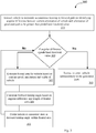
- Fig. 3 illustrates a flowchart showing a method for guiding an autonomous vehicle in a forward path in real-time, in accordance with some embodiments of the present disclosure.
- the method 300 may comprise one or more steps for guiding the autonomous vehicle in a forward path in real-time, in accordance with some embodiments of the present disclosure.
- the method 300 may be described in the general context of computer executable instructions.
- computer executable instructions can include routines, programs, objects, components, data structures, procedures, modules, and functions, which perform particular functions or implement particular abstract data types.
- the order in which the method 300 is described is not intended to be construed as a limitation, and any number of the described method blocks can be combined in any order to implement the method. Additionally, individual blocks may be deleted from the methods without departing from the scope of the subject matter described herein. Furthermore, the method can be implemented in any suitable hardware, software, firmware, or combination thereof.
- the steering termination module 221 receives the angular velocity from the communication module 219.
- the ECU 101 identifies angular difference between the orientation of the vehicle and the orientation of the generated path.
- the steering termination module 221 may generate the signal to be communicated to the main controller 103 for terminating steering of the vehicle in the forward path.
- the predefined threshold value is "60".
- the steering termination module 221 generates the signal for terminating steering of the vehicle in the forward path.
- the predefined threshold value may vary based on obstacles in the forward path, curvature of the forward path, vehicle capacity, etc.
- the ECU 101 checks, for every predefined time interval, whether the angular difference is less than the predefined threshold value. In case the angular difference is less than the predefined threshold value, the method moves to block 305. However, if the angular difference is greater than the predefined threshold value, the method moves to block 307.
- the ECU 101 instructs the main controller 103 to steer the vehicle in / according to the generated path autonomously.
- the frontal area estimation module 223 estimates the frontal area for the vehicle based on the current speed, orientation, and width of the vehicle.
- the frontal area may be in a predefined geometrical shape.
- the forward turning angle calculator 225 calculates the forward turning angle for the vehicle based on the angular difference and length of the frontal area.
- the guiding module 227 guides the vehicle to manoeuvre steering of the vehicle at the forward turning angle towards the generated path within the frontal area.
- Fig. 4a shows an exemplary embodiment to guide a vehicle, i.e., car, to manoeuvre steering in the frontal area in accordance with some embodiments of the present disclosure.
- the environment 400 illustrates a scenario of guiding a car to manoeuvre steering in forward direction in an exemplary embodiment of the present disclosure.
- the environment 400 comprises an autonomous car 401 moving in / according to a generated path 403, which is a curve.
- the autonomous car 401 may include the ECU 101 and one or more sensors 105 (not shown explicitly in the Fig. 4a ).
- the one or more sensors 105 may be placed at predefined positions on the car 401.
- the one or more sensors 105 may be placed at top view or at front of the car 401.
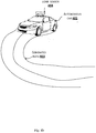
- Fig. 4b shows an exemplary autonomous car with sensor coverage for monitoring nearby field of a generated path for autonomously steering in accordance with some embodiments of the present disclosure.
- an autonomous car 401 comprises a LIDAR sensor 404, mounted on at top portion of the autonomous car 401.
- the LIDAR sensor 404 may monitor the generated path 403 and may check for one or more obstacles in the generated path 403.
- the ECU 101 of the car 401 instructs to terminate autonomous steering of the car 401 in the generated path 403. Further, the ECU 101 of the car 401 estimates the frontal area for the car 401 based on the current speed, orientation, and width of the car 401.
- the frontal area is a trapezoid area 405.
- the ECU 101 of the car 401 determines a central orientation line 407 (e.g., using geometry) and associated array points on the line based on current position and orientation of the car 401. In an embodiment, the number of array points depends and based on the current speed of the car 401.
- the array points span along the central orientation line and may determine the length of the trapezoid area 405.
- the ECU 101 of the car 401 determines a line perpendicular to the central orientation line 407 that passes through the array point. In this manner, a plurality of perpendicular lines, each passing through a respective array point, are determined.
- the ECU 101 identifies the plurality of direction points on each of the perpendicular lines, on both sides of the central orientation line 407.
- the plurality of direction points on the side of the central orientation line that is proximate to the generated path, e.g., the right side of the central orientation line 407 in Fig. 4 are traced for equal number for each perpendicular line. As shown in Fig.
- the ECU 101 of the car 401 calculates a forward turning angle (TP 411) as discussed above, for example with reference to Fig. 2 and shown in Fig. 4c and guides the car 401 to manoeuvre steering at the TP 411.
- TP 411 forward turning angle
- Fig. 4c shows an exemplary representation of forward turning angle in accordance with some embodiment of present disclosure.
- the TP 411 is highlighted, which is smaller than the TD 409.
- the ECU 101 of the car 401 estimates the trapezoid area 405 at every predefined time interval and continuously calculates the TP 411 and guides the car 401 at the TP 411 until the angular difference becomes less than the predefined threshold value i.e., less than "30".
- the TP 411 is calculated to be "50 degrees and the predefined time interval is 300 millisecond minute.
- the ECU 101 of the car 401 guides the car 401 at the TP 411 "50 degree” for 300 millisecond. While, the car 401 is guided, the ECU 101 checks the angular difference with the predefined threshold value "30", estimates a new trapezoid area, and calculates TP 411 as "40 degree”.
- the ECU 101 guides the car 401 with the TP 411 as "40 degrees” for 300 millisecond. The process repeats until deviation between the orientation of the car 401 and orientation of the generated path 403 reduces below the predefined threshold, i.e., "30".
- the ECU 101 of the car 401 instructs the main controller 103 to steer the car 401 autonomously in the generated path 403.
- the present disclosure is performed in real-time.
- the present disclosure discloses a method and an autonomous navigation system for guiding the vehicle in the forward path during any steep curve.
Landscapes
- Engineering & Computer Science (AREA)
- Transportation (AREA)
- Mechanical Engineering (AREA)
- Automation & Control Theory (AREA)
- Combustion & Propulsion (AREA)
- Chemical & Material Sciences (AREA)
- General Physics & Mathematics (AREA)
- Remote Sensing (AREA)
- Physics & Mathematics (AREA)
- Aviation & Aerospace Engineering (AREA)
- Radar, Positioning & Navigation (AREA)
- Human Computer Interaction (AREA)
- Traffic Control Systems (AREA)
- Business, Economics & Management (AREA)
- Medical Informatics (AREA)
- Game Theory and Decision Science (AREA)
- Evolutionary Computation (AREA)
- Artificial Intelligence (AREA)
- Health & Medical Sciences (AREA)
- Control Of Position, Course, Altitude, Or Attitude Of Moving Bodies (AREA)
Abstract
Description
- The present disclosure relates in general to field of automobile (automotive) industry. Particularly, but not exclusively, the present disclosure relates to a method and system for guiding an autonomous vehicle in a forward path in real-time.
- Advancement in technology has led to numerous developments in various fields, and the field of automobile is no exception. The advancement in field of automobile has given rise to autonomous vehicle technology which aims to reduce energy consumption, pollution, and congestion while at the same time increasing road safety. The autonomous vehicle (also known as, a driverless vehicle) uses various sensing devices and techniques to detect their surroundings and path.
- The autonomous vehicles today, can traverse a path to reach a destination point by generating command velocities such as, linear and angular velocity to follow a planned navigation path. However, sometimes while aligning with the planned navigation path, there might exist deviation between the planned path and vehicle orientation. The deviation may become such that the vehicle navigation system would generate an angular velocity, based on vehicle's current speed, which is beyond the vehicle's turning capability. Also, when a path in which the vehicle is traveling has a steep curve (a sharp turn), the vehicle may not be able to traverse the curve easily, and manual intervention may be required in such circumstances. Existing autonomous vehicles do not provide an efficient solution to address the above-mentioned problems.
- The information disclosed in this background of the disclosure section is only for enhancement of understanding of the general background of the invention and should not be taken as an acknowledgement or any form of suggestion that this information forms the prior art already known to a person skilled in the art.
- In an embodiment, the present disclosure relates to a method for guiding an autonomous vehicle in a forward path in real-time. The method comprises instructing the vehicle to terminate autonomous steering in a forward path, on identifying an angular difference between a current orientation of the vehicle and orientation of a generated path to be greater than a predefined threshold value, and performing, for every predefined time interval, until the angular difference is less than the predefined threshold value, steps of estimating a frontal area for the vehicle based on a current speed, an orientation, and a width of the vehicle, calculating a forward turning angle based on the angular difference and a length of the frontal area and guiding the vehicle to manoeuvre steering at the forward turning angle within the frontal area.
- In an embodiment, the present disclosure relates to an Electronic Circuit Unit (ECU) of an autonomous vehicle for guiding the autonomous vehicle in a forward path in real-time. The ECU is configured to instruct the vehicle to terminate autonomous steering in a forward path, on identifying an angular difference between a current orientation of the vehicle and orientation of a generated path to be greater than a predefined threshold value and further configured to perform, for every predefined time interval, until the angular difference is less than the predefined threshold value, steps of estimating a frontal area for the vehicle based on a current speed, an orientation, and a width of the vehicle, calculating a forward turning angle based on the angular difference and a length of the frontal area and guiding the vehicle to manoeuvre steering at the forward turning angle within the frontal area.
- In an embodiment the present disclosure also relates to a computer-implemented method for guiding an autonomous vehicle in real-time according to a generated path. The method comprises: instructing the vehicle to terminate autonomous steering according to the generated path upon determining that an angular difference between a current orientation of the vehicle and an orientation of the generated path is greater than a predefined threshold; and for every predefined time interval, until the angular difference becomes less than the predefined threshold: estimating a frontal area for the vehicle based on a current speed, an orientation, and a width of the vehicle; calculating a forward turning angle based on the angular difference and a length of the frontal area; and guiding the vehicle within the frontal area to steer at the forward turning angle towards the generated path.
- The foregoing summary is illustrative only and is not intended to be in any way limiting. In addition to the illustrative aspects, embodiments, and features described above, further aspects, embodiments, and features will become apparent by reference to the drawings and the following detailed description.
- The accompanying drawings, which are incorporated in and constitute a part of this disclosure, illustrate exemplary embodiments and, together with the description, serve to explain the disclosed principles. In the figures, the left-most digit(s) of a reference number identifies the figure in which the reference number first appears. The same numbers are used throughout the figures to reference like features and components. Some embodiments of system and/or methods in accordance with embodiments of the present subject matter are now described, by way of example only, and with reference to the accompanying figures, in which:
-
Fig. 1 illustrates an exemplary block diagram of an autonomous navigation system for guiding an autonomous vehicle in a forward path in real-time, in accordance with some embodiments of the present disclosure; -
Fig. 2 is a block diagram of internal architecture of an ECU configured to guide an autonomous vehicle in a forward path in real-time, in accordance with some embodiments of the present disclosure; -
Fig. 3 illustrates a flowchart showing a method for guiding an autonomous vehicle in a forward path in real-time, in accordance with some embodiments of the present disclosure; -
Fig. 4a shows an exemplary embodiment to guide a vehicle, i.e., a car to manoeuvre steering in the frontal area in accordance with some embodiments of the present disclosure; -
Fig. 4b shows an exemplary autonomous car with sensor coverage for monitoring nearby field of a generated path for autonomously steering in accordance with some embodiments of the present disclosure; and -
Fig. 4c shows an exemplary representation of forward turning angle in accordance with some embodiment of present disclosure. - It should be appreciated by those skilled in the art that any block diagrams herein represent conceptual views of illustrative systems embodying the principles of the present subject matter. Similarly, it will be appreciated that any flow charts, flow diagrams, state transition diagrams, pseudo code, and the like represent various processes which may be substantially represented in computer readable medium and executed by a computer or processor, whether or not such computer or processor is explicitly shown.
- In the present document, the word "exemplary" is used herein to mean "serving as an example, instance, or illustration." Any embodiment or implementation of the present subject matter described herein as "exemplary" is not necessarily to be construed as preferred or advantageous over other embodiments.
- While the disclosure is susceptible to various modifications and alternative forms, specific embodiment thereof has been shown by way of example in the drawings and will be described in detail below. It should be understood, however that it is not intended to limit the disclosure to the particular forms disclosed, but on the contrary, the disclosure is to cover all modifications, equivalents, and alternative falling within the scope of the disclosure.
- The terms "comprises", "comprising", or any other variations thereof, are intended to cover a non-exclusive inclusion, such that a setup, device or method that comprises a list of components or steps does not include only those components or steps but may include other components or steps not expressly listed or inherent to such setup or device or method. In other words, one or more elements in a system or apparatus proceeded by "comprises... a" does not, without more constraints, preclude the existence of other elements or additional elements in the system or method.
- In the following detailed description of the embodiments of the disclosure, reference is made to the accompanying drawings that form a part hereof, and in which are shown by way of illustration specific embodiments in which the disclosure may be practiced. These embodiments are described in sufficient detail to enable those skilled in the art to practice the disclosure, and it is to be understood that other embodiments may be utilized and that changes may be made without departing from the scope of the present disclosure. The following description is, therefore, not to be taken in a limiting sense.
- The present disclosure relates to a method and an autonomous navigation system for guiding a vehicle in a forward path in real-time. In an embodiment, an autonomous vehicle refers to a driverless vehicle. The autonomous vehicle may follow a pre-defined path generated based on a source and a destination point. The autonomous navigation system may instruct to terminate autonomous steering in the forward path according to the generated path, whenever an angular difference between a current orientation of the vehicle and orientation of the generated path is greater than a predefined threshold value. In an embodiment, the autonomous vehicle may identify the angular difference between the current orientation of the vehicle and orientation of the generated path at pre-defined intervals, while the autonomous vehicle follows the generated path. The autonomous navigation system may estimate a frontal area in the forward path based on a current speed, orientation, and width of the vehicle and may calculate a forward turning angle for steering the vehicle. The forward turning angle may be calculated based on the angular difference and a length of the frontal area. The vehicle may be guided to manoeuvre at the forward turning angle within the frontal area, such as towards the generated path. The autonomous navigation system may perform the estimation of frontal area, calculation of the forward turning angle, and guiding of the vehicle for every predefined time interval, until the angular difference becomes less than the predefined threshold value. In an embodiment, the predefined intervals associated with the autonomous vehicle while following the generated path and the predefined time interval during calculation of frontal area may be the same. The present disclosure discloses a method for navigating a forward path having a steep curvature, such as a path having a curvature that is beyond the vehicle's turning capability.
-
Fig. 1 illustrates an exemplary block diagram of an autonomous navigation system for guiding an autonomous vehicle in a forward path in real-time, in accordance with some embodiments of the present disclosure. As shown inFig. 1 , the autonomous navigation system 100 comprises an Electronic Control Unit (ECU) 101, amain controller 103, asensor 105A, asensor 105B, .................., and asensor 105N. In an embodiment, thesensor 105A, thesensor 105B, ............. and thesensor 105N may be collectively represented as one ormore sensors 105. In an embodiment, the one ormore sensors 105 may include, a Light Ranging and Detection (LIDAR) system, an ultrasound sensor, a camera, a proximity sensor, and the like. A person skilled in the art would understand that the one ormore sensors 105 may include any other sensor not mentioned explicitly in the present disclosure. - In an embodiment, the
main controller 103 may be used for autonomously navigating the vehicle in a generated path. For example, the generated path may be a primary path mapped by themain controller 103 to navigate the vehicle from a source location to a destination location. In an embodiment, the generated path may include a straight path, a curved path, or a path of any other orientation or shape. - The
ECU 101 may be used to guide the autonomous vehicle in the forward path according to the generated path in real-time. In an embodiment, theECU 101 may be integrated with themain controller 103 or may be a standalone unit associated with themain controller 103. TheECU 101 may periodically receive an angular velocity of the vehicle calculated by themain controller 103. Further, theECU 101 may check an angular difference between a current orientation of the vehicle and an orientation of the generated path at pre-defined intervals, on receiving the angular velocity. In case theECU 101 identifies that the angular difference is greater than a predefined threshold value, then theECU 101 may immediately instruct themain controller 103 to terminate an autonomous steering of the vehicle in the forward path. In an embodiment, the angular difference being more than the predefined threshold value indicates that an angular velocity required by the vehicle to mitigate the deviation is beyond the vehicle turning capacity. - The
ECU 101 may estimate a frontal area for the vehicle based on a current speed, orientation, and width of the vehicle. In an embodiment, the frontal area may be the area in front of the vehicle within which the vehicle may manoeuvre with a smooth curve, such as a curve that is within the vehicle's turning capability. For example, a vehicle with high speed may estimate the frontal area of large distance. That is, the higher is the speed with which the vehicle travels, the longer is the estimated frontal area. - In an embodiment, the frontal area may be in a pre-defined geometrical shape. The pre-defined geometrical shape includes shapes such as, square, trapezoid, rectangle, and the like. In an embodiment, the frontal area is free from one or more obstacles, or all obstacles. Further, the
ECU 101 may calculate a forward turning angle for the vehicle based on the angular difference and a length of the frontal area. Further, theECU 101 may guide the vehicle to manoeuvre steering at the forward turning angle within the frontal area. TheECU 101 may perform the estimation of the frontal area, calculation of the forward turning angle and guidance for every predefined time interval, until the angular difference is less than the predefined threshold. -
Fig. 2 illustrates an internal architecture of an ECU configured to guide an autonomous vehicle in a forward path in real-time in accordance with some embodiments of the present disclosure. TheECU 101 may include at least one Central Processing Unit ("CPU" or "processor") 205 and amemory 203 storing instructions executable by the at least oneprocessor 205. Theprocessor 205 may comprise at least one data processor for executing program components for executing user or system-generated requests. Thememory 203 is communicatively coupled to theprocessor 205. TheECU 101 further comprises an Input/Output (I/O)interface 201. The I/O interface 201 is coupled with theprocessor 205 through which an input signal or/and an output signal is communicated. - In an embodiment,
data 207 may be stored within thememory 203. Thedata 207 may include, for example, asensor data 209, afrontal area 211, aforward turning angle 213, andother data 215. - The
sensor data 209 may include information regarding all views and directions around the vehicle. The one ormore sensors 105 may detect the one or more obstacles in the generated path and provide information regarding the obstacles to theECU 101. For example, the one or more obstacles may include stationary and movable obstacles. The stationary obstacles may include, a stone, a pit etc. The movable obstacles may include a person, another vehicle etc. Further, thesensor data 209 may include the predefined threshold value of angular difference between the orientation of the vehicle and the orientation of the generated path. - The
frontal area 211 may be an area estimated upon identifying (determining) that the angular difference between the current orientation of the vehicle and orientation of the generated path is greater than the predefined threshold value. Thefrontal area 211 may be estimated based on the current speed, the orientation, and width of the vehicle. - The
forward turning angle 213 may be a turning angle calculated based on the angular difference and the length of thefrontal area 211. In an embodiment, theforward turning angle 213 may be calculated until the angular difference becomes less than the predefined threshold value. - The
other data 215 may comprise but is not limited to traffic information, terrain information, and the like. - In an embodiment, the
data 207 in thememory 203 is processed bymodules 217 of theECU 101. As used herein, the term module refers to an application specific integrated circuit (ASIC), an electronic circuit, a field-programmable gate arrays (FPGA), Programmable System-on-Chip (PSoC), a combinational logic circuit, and/or other suitable components that provide the described functionality. Themodules 217 when configured with the functionality defined in the present disclosure will result in a novel hardware. - In one implementation, the
modules 217 may include, for example, acommunication module 219, asteering termination module 221, a frontalarea estimation module 223, a forwardturning angle calculator 225, a guidingmodule 227 andother modules 229. It will be appreciated that suchaforementioned modules 217 may be represented as a single module or a combination of different modules. - The
communication module 219 may be used for communication between theECU 101 and other units (not shown in figures) of the vehicle. In an embodiment, the other units may comprise, but are not limited to, a transmission control unit, a door unit, a steering controller, an indication unit, etc. For example, thecommunication module 219 may receive information regarding the generated path and associated angular velocity from themain controller 103. Further, thecommunication module 219 may communicate the information received from themain controller 103 to theECU 101. In an embodiment, thecommunication module 219 may convey instructions to themain controller 103. In an embodiment, thecommunication module 219 may receivesensor data 209 from the one ormore sensors 105 and provide thesensor data 209 to theECU 101. Also, thecommunication module 219 may communicate instructions to the one ormore sensors 105 regarding activation and deactivation of the one ormore sensors 105. - The
steering termination module 221 may generate a signal to themain controller 103 upon identifying or otherwise determining the angular difference to be greater than the predefined threshold value. The signal may indicate instruction for termination of the autonomous steering in the forward path. - The frontal
area estimation module 223 may estimate the frontal area for the vehicle. The forwardturning angle calculator 225 may calculate the forward turning angle towards the generated path for the vehicle. The guidingmodule 227 may guide the vehicle to manoeuvre steering (to steer, to perform a steering manoeuvre, or alike) within the frontal area, such as to steer the vehicle at the forward turning angle towards the generated path for the vehicle. - The estimation of the frontal area, calculation of the forward turning angle and guidance to manoeuvre steering within the frontal area is performed for every predefined time interval until the angular difference becomes less than the predefined threshold value.
- The frontal
area estimation module 223 may estimate the frontal area for the vehicle once thesteering termination module 221 terminates the steering of the vehicle in the generated path. The frontalarea estimation module 223 may estimate the frontal area based on the current speed, orientation, and width of the vehicle. In an embodiment, the frontalarea estimation module 223 estimates the frontal area which is free from the one or more obstacles or all obstacles. In an embodiment, the frontal area may be in a predefined geometrical shape such as, trapezoid, rectangle, square, etc. - The frontal
area estimation module 223 may estimate the frontal area by determining a central orientation line of the vehicle and associated array points on the central orientation line from a current position of the vehicle. In an embodiment, the number of the array points is based on the current speed of the vehicle. For each of the array points, the frontalarea estimation module 223 may identify a line perpendicular to the central orientation line, passing through the array point on both sides of the central orientation line. Further, the frontalarea estimation module 223 may identify a plurality of direction points for each of the perpendicular lines and estimate the frontal area based on the plurality of direction points of each of the perpendicular lines on both sides of the central orientation line. - In an embodiment, the plurality of direction points may be equal in number with respect to the central orientation line on each perpendicular line identified towards the generated path. an embodiment, the plurality of direction points on each perpendicular line identified towards opposite direction of the generated path reduces from the nearest point of the vehicle to the furthest point of the geometrical shape of the frontal area.
- In other words, the perpendicular lines have the same number of direction points on the side of the central orientation line that is proximate/towards/ on the same side as the generated path. These direction points may, for example, form a rectangular part of the frontal area. The number of direction points, comprised in the perpendicular lines on the side of the central orientation line that is distant from/opposite the side with the generated path, is the largest for the perpendicular line that is the closest to the vehicle and the smallest for the perpendicular line that is the furthest away from the vehicle, e.g., a single point on the central orientation line, thereby identifying a corner of the frontal area. These direction points may, for example, form a triangular part of the frontal area. In this manner, a frontal area having a trapezoid shape may be formed, with a slope of the trapezoid being formed on the side of the central orientation line that is distant from/opposite the side with the generated path.
- In an embodiment, estimating the frontal area comprises searching for the frontal area away from the generated path based on orientation of the vehicle. For example, estimating the frontal area may comprise searching for an area that is in front of the vehicle, has the same orientation as the vehicle, and is proximate to the generate path on the side that is away from the direction of the curvature of the generated path.
- The forward
turning angle calculator 225 may calculate the forward turning angle towards the generated path based on the angular difference and a length of the frontal area. For example, the forwardturning angle calculator 225 may calculate the forward turning angle by considering the part of the frontal area in which the plurality of direction points are equal in number with respect to the central orientation line of each perpendicular line identified towards the generated path (e.g., the rectangular part in the above-described example). The forwardturning angle calculator 225 may determine a diagonal line in the part by drawing a straight line between two opposite corners of the part of the frontal area (e.g., the corner falling on the central orientation line and the opposite corner in the above-described example). Further, the forwardturning angle calculator 225 may calculate a turning angle between the diagonal line and a longer side of the part of the frontal area (e.g., the slope in the above described example). - The guiding
module 227 may receive the forward turning angle and details regarding the frontal area from the forwardturning angle calculator 225 and the frontalarea estimation module 223 respectively. The guidingmodule 227 may guide the vehicle to manoeuvre steering within the frontal area at the forward turning angle. In an embodiment, the vehicle may be guided at the forward turning angle determined for every predefined time interval, until the angular difference becomes less than the predefined threshold value. Once the vehicle has been guided as described above, and the angular difference becomes less than the predefined threshold value, the guidingmodule 227 may provide/pass control to themain controller 103 to follow the generated path autonomously. - In an embodiment, the
other modules 229 may include, but is not limited to, an indication module to indicate one or more obstacles in the generated path. -
Fig. 3 illustrates a flowchart showing a method for guiding an autonomous vehicle in a forward path in real-time, in accordance with some embodiments of the present disclosure. - As illustrated in
Fig. 3 , themethod 300 may comprise one or more steps for guiding the autonomous vehicle in a forward path in real-time, in accordance with some embodiments of the present disclosure. Themethod 300 may be described in the general context of computer executable instructions. Generally, computer executable instructions can include routines, programs, objects, components, data structures, procedures, modules, and functions, which perform particular functions or implement particular abstract data types. - The order in which the
method 300 is described is not intended to be construed as a limitation, and any number of the described method blocks can be combined in any order to implement the method. Additionally, individual blocks may be deleted from the methods without departing from the scope of the subject matter described herein. Furthermore, the method can be implemented in any suitable hardware, software, firmware, or combination thereof. - At
step 301, thesteering termination module 221 receives the angular velocity from thecommunication module 219. TheECU 101 identifies angular difference between the orientation of the vehicle and the orientation of the generated path. When the angular difference is more than the predefined threshold, thesteering termination module 221 may generate the signal to be communicated to themain controller 103 for terminating steering of the vehicle in the forward path. For example, let us consider that the predefined threshold value is "60". When the angular difference is more than "60 , thesteering termination module 221 generates the signal for terminating steering of the vehicle in the forward path. In an embodiment, the predefined threshold value may vary based on obstacles in the forward path, curvature of the forward path, vehicle capacity, etc. - At
step 303, theECU 101 checks, for every predefined time interval, whether the angular difference is less than the predefined threshold value. In case the angular difference is less than the predefined threshold value, the method moves to block 305. However, if the angular difference is greater than the predefined threshold value, the method moves to block 307. - At
block 305, theECU 101 instructs themain controller 103 to steer the vehicle in / according to the generated path autonomously. - At
step 307, the frontalarea estimation module 223 estimates the frontal area for the vehicle based on the current speed, orientation, and width of the vehicle. In an embodiment, the frontal area may be in a predefined geometrical shape. - At
step 309, the forwardturning angle calculator 225 calculates the forward turning angle for the vehicle based on the angular difference and length of the frontal area. - At
step 311, the guidingmodule 227 guides the vehicle to manoeuvre steering of the vehicle at the forward turning angle towards the generated path within the frontal area. -
Fig. 4a shows an exemplary embodiment to guide a vehicle, i.e., car, to manoeuvre steering in the frontal area in accordance with some embodiments of the present disclosure. - As shown in
Fig. 4a , theenvironment 400 illustrates a scenario of guiding a car to manoeuvre steering in forward direction in an exemplary embodiment of the present disclosure. Theenvironment 400 comprises an autonomous car 401 moving in / according to a generatedpath 403, which is a curve. The autonomous car 401 may include theECU 101 and one or more sensors 105 (not shown explicitly in theFig. 4a ). The one ormore sensors 105 may be placed at predefined positions on the car 401. For example, the one ormore sensors 105 may be placed at top view or at front of the car 401. -
Fig. 4b shows an exemplary autonomous car with sensor coverage for monitoring nearby field of a generated path for autonomously steering in accordance with some embodiments of the present disclosure. In theFig. 4b , an autonomous car 401 comprises aLIDAR sensor 404, mounted on at top portion of the autonomous car 401. TheLIDAR sensor 404 may monitor the generatedpath 403 and may check for one or more obstacles in the generatedpath 403. - Further, returning to
Fig. 4a , theECU 101 of the car 401 may receive an angular velocity (TD) 409 associated with the generatedpath 403 from themain controller 103 of the car 401 at predefined time of intervals. Using theTD 409, theECU 101 of the car 401 identifies angular difference between the orientation of the car 401 and the orientation of the generatedpath 403. The identified angular difference is compared with the predefined threshold value of the angular difference. In case the angular difference is greater than the pre-defined threshold value, theECU 101 of the car 401 instructs to terminate steering of the car 401 in /according to the generatedpath 403. - Consider that the angular difference between the orientation of the car 401 and the orientation of the generated
path 403 is "60" and the predefined threshold value is "30". In such conditions, theECU 101 of the car 401 instructs to terminate autonomous steering of the car 401 in the generatedpath 403. Further, theECU 101 of the car 401 estimates the frontal area for the car 401 based on the current speed, orientation, and width of the car 401. - As shown in
Fig. 4a , the frontal area is atrapezoid area 405. A person skilled in the art would understand thatFig. 4a is an exemplary embodiment and the frontal area may be in any predefined geometrical shape. TheECU 101 of the car 401 determines a central orientation line 407 (e.g., using geometry) and associated array points on the line based on current position and orientation of the car 401. In an embodiment, the number of array points depends and based on the current speed of the car 401. - For example, the higher the speed, the more array points will be considered to define the length of the
area 405. The array points span along the central orientation line and may determine the length of thetrapezoid area 405. - Further, for each of the array points, the
ECU 101 of the car 401 determines a line perpendicular to thecentral orientation line 407 that passes through the array point. In this manner, a plurality of perpendicular lines, each passing through a respective array point, are determined. TheECU 101 identifies the plurality of direction points on each of the perpendicular lines, on both sides of thecentral orientation line 407. The plurality of direction points on the side of the central orientation line that is proximate to the generated path, e.g., the right side of thecentral orientation line 407 inFig. 4 , are traced for equal number for each perpendicular line. As shown inFig. 4a , the direction points on the perpendicular line towards left side of thecentral orientation line 407 are reduced in numbers from nearest point of car 401 to furthest point of thetrapezoid area 405, thus maintaining a slope of thetrapezoid area 405. Once thetrapezoid area 405 is estimated, theECU 101 of the car 401 calculates a forward turning angle (TP 411) as discussed above, for example with reference toFig. 2 and shown inFig. 4c and guides the car 401 to manoeuvre steering at theTP 411. -
Fig. 4c shows an exemplary representation of forward turning angle in accordance with some embodiment of present disclosure. As shown in theFig. 4c , theTP 411 is highlighted, which is smaller than theTD 409. TheECU 101 of the car 401 estimates thetrapezoid area 405 at every predefined time interval and continuously calculates theTP 411 and guides the car 401 at theTP 411 until the angular difference becomes less than the predefined threshold value i.e., less than "30". - Consider that the
TP 411 is calculated to be "50 degrees and the predefined time interval is 300 millisecond minute. In such case, theECU 101 of the car 401 guides the car 401 at theTP 411 "50 degree" for 300 millisecond. While, the car 401 is guided, theECU 101 checks the angular difference with the predefined threshold value "30", estimates a new trapezoid area, and calculatesTP 411 as "40 degree". TheECU 101 guides the car 401 with theTP 411 as "40 degrees" for 300 millisecond. The process repeats until deviation between the orientation of the car 401 and orientation of the generatedpath 403 reduces below the predefined threshold, i.e., "30". Once, the angular difference is less than the predefined threshold value" 30", theECU 101 of the car 401 instructs themain controller 103 to steer the car 401 autonomously in the generatedpath 403. - In an embodiment, the present disclosure is performed in real-time.
- In an embodiment, the present disclosure discloses a method and an autonomous navigation system for guiding the vehicle in the forward path during any steep curve.
- A description of an embodiment with several components in communication with each other does not imply that all such components are required. On the contrary a variety of optional components are described to illustrate the wide variety of possible embodiments of the invention.
- When a single device or article is described herein, it will be readily apparent that more than one device/article (whether or not they cooperate) may be used in place of a single device/article. Similarly, where more than one device or article is described herein (whether or not they cooperate), it will be readily apparent that a single device/article may be used in place of the more than one device or article or a different number of devices/articles may be used instead of the shown number of devices or programs. The functionality and/or the features of a device may be alternatively embodied by one or more other devices which are not explicitly described as having such functionality/features. Thus, other embodiments of the invention need not include the device itself.
- The illustrated operations of
Figure 3 show certain events occurring in a certain order. In alternative embodiments, certain operations may be performed in a different order, modified or removed. Moreover, steps may be added to the above described logic and still conform to the described embodiments. Further, operations described herein may occur sequentially or certain operations may be processed in parallel. Yet further, operations may be performed by a single processing unit or by distributed processing units. - Finally, the language used in the specification has been principally selected for readability and instructional purposes, and it may not have been selected to delineate or circumscribe the inventive subject matter. It is therefore intended that the scope of the invention be limited not by this detailed description, but rather by any claims that issue on an application based here on. Accordingly, the disclosure of the embodiments of the invention is intended to be illustrative, but not limiting, of the scope of the invention, which is set forth in the following claims.
- While various aspects and embodiments have been disclosed herein, other aspects and embodiments will be apparent to those skilled in the art. The various aspects and embodiments disclosed herein are for purposes of illustration and are not intended to be limiting, with the true scope being indicated by the following claims.
Claims (11)
- A computer-implemented method for guiding an autonomous vehicle in a forward path in real-time, the method comprising:instructing the vehicle to terminate autonomous steering in the forward path according to a generated path upon identifying an angular difference between a current orientation of the vehicle and an orientation of the generated path to be greater than a predefined threshold value; andperforming, for every predefined time interval, until the angular difference becomes less than the predefined threshold value, steps of:estimating a frontal area for the vehicle based on a current speed, an orientation, and a width of the vehicle;calculating a forward turning angle based on the angular difference and a length of the frontal area; andguiding the vehicle to manoeuvre steering within the frontal area at the forward turning angle towards the generated path.
- The method as claimed in claim 1, wherein the frontal area is in a predefined geometrical shape.
- The method as claimed in claim 1 or claim 2, wherein the frontal area is a trapezoid area.
- The method as claimed in of claims 1-3, wherein the frontal area is free from one or more obstacles.
- The method as claimed in any of claims 1-4, wherein the frontal area is estimated by:determining a central orientation line and associated array points on the central orientation line, from a current position of the vehicle;identifying, for each of the array points, a line perpendicular to the central orientation line, passing through the array point on both sides of the central orientation line;identifying a plurality of direction points for each of the perpendicular lines; andestimating the frontal area based on the plurality of direction points on each of the perpendicular lines on both sides of the central orientation line.
- The method as claimed in claim 5, wherein a number of the array points is based on the current speed of the vehicle.
- The method as claimed in claim 5 or claim 6, wherein each perpendicular line has an equal number of direction points identified with respect to the central orientation line on the side proximate to the generated path.
- The method as claimed in any of claims 5-7, wherein a number of direction points, identified on each perpendicular line with respect to the central orientation line on the side distant from the generated path, reduces from a point of the frontal area nearest to the vehicle to a point of the frontal area furthest from the vehicle.
- The method as claimed in any of claims 1-7, wherein estimating the frontal area comprises searching for the frontal area away from the generated path based on orientation of the vehicle.
- An Electronic Control Unit for guiding an autonomous vehicle in a forward path in real-time, the Electronic Control Unit comprising:a processor; anda memory storing instructions which, when executed by the processor, cause the Electronic Control Unit to perform the method as claimed in any of claims 1-9.
- A computer-readable storage medium having stored thereon a set of computer-executable instructions which, when executed by one or more processors, cause a computer to perform the method as claimed in claims 1-9.
Applications Claiming Priority (1)
| Application Number | Priority Date | Filing Date | Title |
|---|---|---|---|
| IN201741045222 | 2017-12-15 |
Publications (2)
| Publication Number | Publication Date |
|---|---|
| EP3498574A1 true EP3498574A1 (en) | 2019-06-19 |
| EP3498574B1 EP3498574B1 (en) | 2022-07-27 |
Family
ID=61827530
Family Applications (1)
| Application Number | Title | Priority Date | Filing Date |
|---|---|---|---|
| EP18164089.7A Active EP3498574B1 (en) | 2017-12-15 | 2018-03-26 | Method and system for guiding an autonomous vehicle in a forward path in real-time |
Country Status (2)
| Country | Link |
|---|---|
| US (1) | US10860021B2 (en) |
| EP (1) | EP3498574B1 (en) |
Cited By (1)
| Publication number | Priority date | Publication date | Assignee | Title |
|---|---|---|---|---|
| CN110362080A (en) * | 2019-07-12 | 2019-10-22 | 深圳市哈威飞行科技有限公司 | Method for optimizing route, device and the computer readable storage medium of differential unmanned boat |
Families Citing this family (4)
| Publication number | Priority date | Publication date | Assignee | Title |
|---|---|---|---|---|
| SE543484C2 (en) * | 2018-03-06 | 2021-03-02 | Cargotec Patenter Ab | Cargo handling vehicle for navigation in narrow aisles and method therefore |
| CN113002399A (en) * | 2019-12-20 | 2021-06-22 | 锥能机器人(上海)有限公司 | Method and apparatus for carrying goods shelf, machine readable medium and system |
| US20220194469A1 (en) * | 2020-12-17 | 2022-06-23 | Argo AI, LLC | Autonomous vehicle steering juke event detector |
| CN116279802B (en) * | 2023-03-28 | 2025-07-25 | 东风柳州汽车有限公司 | Vehicle transverse control method, device, equipment and storage medium |
Citations (3)
| Publication number | Priority date | Publication date | Assignee | Title |
|---|---|---|---|---|
| US20090028388A1 (en) * | 2007-07-24 | 2009-01-29 | Nec Electronics Corporation | On-vehicle image processing apparatus |
| US20150210274A1 (en) * | 2014-01-30 | 2015-07-30 | Mobileye Vision Technologies Ltd. | Systems and methods for lane end recognition |
| US20150353082A1 (en) * | 2014-06-05 | 2015-12-10 | Carnegie Mellon University | Unified motion planning algorithm for autonomous driving vehicle in obstacle avoidance maneuver |
Family Cites Families (7)
| Publication number | Priority date | Publication date | Assignee | Title |
|---|---|---|---|---|
| US7706917B1 (en) * | 2004-07-07 | 2010-04-27 | Irobot Corporation | Celestial navigation system for an autonomous robot |
| US8160760B2 (en) * | 2009-09-23 | 2012-04-17 | GM Global Technology Operations LLC | Human-machine interface device for an autonomic vehicle control system |
| CN103858155B (en) * | 2011-09-26 | 2017-10-03 | 丰田自动车株式会社 | The driving assist system of vehicle |
| US9428187B2 (en) * | 2014-06-05 | 2016-08-30 | GM Global Technology Operations LLC | Lane change path planning algorithm for autonomous driving vehicle |
| US9229453B1 (en) * | 2014-08-29 | 2016-01-05 | GM Global Technology Operations LLC | Unified motion planner for autonomous driving vehicle in avoiding the moving obstacle |
| US9227632B1 (en) * | 2014-08-29 | 2016-01-05 | GM Global Technology Operations LLC | Method of path planning for evasive steering maneuver |
| US10202144B2 (en) | 2015-12-08 | 2019-02-12 | Ford Global Technologies, Llc | Vehicle curvature determination |
-
2018
- 2018-01-31 US US15/884,625 patent/US10860021B2/en active Active
- 2018-03-26 EP EP18164089.7A patent/EP3498574B1/en active Active
Patent Citations (3)
| Publication number | Priority date | Publication date | Assignee | Title |
|---|---|---|---|---|
| US20090028388A1 (en) * | 2007-07-24 | 2009-01-29 | Nec Electronics Corporation | On-vehicle image processing apparatus |
| US20150210274A1 (en) * | 2014-01-30 | 2015-07-30 | Mobileye Vision Technologies Ltd. | Systems and methods for lane end recognition |
| US20150353082A1 (en) * | 2014-06-05 | 2015-12-10 | Carnegie Mellon University | Unified motion planning algorithm for autonomous driving vehicle in obstacle avoidance maneuver |
Cited By (2)
| Publication number | Priority date | Publication date | Assignee | Title |
|---|---|---|---|---|
| CN110362080A (en) * | 2019-07-12 | 2019-10-22 | 深圳市哈威飞行科技有限公司 | Method for optimizing route, device and the computer readable storage medium of differential unmanned boat |
| CN110362080B (en) * | 2019-07-12 | 2022-08-09 | 深圳市哈威飞行科技有限公司 | Path optimization method and device for differential unmanned ship and computer readable storage medium |
Also Published As
| Publication number | Publication date |
|---|---|
| EP3498574B1 (en) | 2022-07-27 |
| US20190187709A1 (en) | 2019-06-20 |
| US10860021B2 (en) | 2020-12-08 |
Similar Documents
| Publication | Publication Date | Title |
|---|---|---|
| EP3498574B1 (en) | Method and system for guiding an autonomous vehicle in a forward path in real-time | |
| US11847838B2 (en) | Recognition device | |
| EP3889722B1 (en) | Generation method and generation system for dynamic target line during automatic driving of vehicle, and vehicle | |
| EP2006181B1 (en) | Avoidance operation calculation device, avoidance control device, vehicle with each of the devices, avoidance operation calculation method, and avoidance control method | |
| US9911330B2 (en) | Driving assistance device and driving assistance method | |
| US9229453B1 (en) | Unified motion planner for autonomous driving vehicle in avoiding the moving obstacle | |
| US9796378B2 (en) | Vehicle travel path generating apparatus | |
| CN105189255B (en) | The prediction of the stroke based on three rank multinomials for driver assistance function | |
| JP6432679B2 (en) | Stop position setting apparatus and method | |
| US10845813B2 (en) | Route setting method and route setting device | |
| JP6959056B2 (en) | Mobile robot control device and control method | |
| JP6654923B2 (en) | Map information output device | |
| EP3456596A1 (en) | Method and device of predicting a possible collision | |
| WO2016117602A1 (en) | Vehicle control device and vehicle control method | |
| US20210354692A1 (en) | Controlling an autonomous vehicle based upon a predicted imminent lane change | |
| CN107010057A (en) | For the method for the track of dodging for finding vehicle | |
| JP6941178B2 (en) | Automatic operation control device and method | |
| US8862326B2 (en) | Vehicle travel assisting device | |
| CN105539434A (en) | Method of path planning for evasive steering maneuver | |
| KR20190045308A (en) | A vehicle judging method, a traveling path correcting method, a vehicle judging device, and a traveling path correcting device | |
| KR20180039900A (en) | Apparatus and method for determining collision possibility according to traveling path scenario and controlling a vehicle | |
| KR101588787B1 (en) | Method for determining lateral distance of forward vehicle and head up display system using the same | |
| US10613540B2 (en) | Method and system for autonomously steering a vehicle in a reverse path in real-time | |
| CN111688703A (en) | Behavior prediction device | |
| JP7214076B2 (en) | Vehicle driving support system |
Legal Events
| Date | Code | Title | Description |
|---|---|---|---|
| PUAI | Public reference made under article 153(3) epc to a published international application that has entered the european phase |
Free format text: ORIGINAL CODE: 0009012 |
|
| STAA | Information on the status of an ep patent application or granted ep patent |
Free format text: STATUS: THE APPLICATION HAS BEEN PUBLISHED |
|
| AK | Designated contracting states |
Kind code of ref document: A1 Designated state(s): AL AT BE BG CH CY CZ DE DK EE ES FI FR GB GR HR HU IE IS IT LI LT LU LV MC MK MT NL NO PL PT RO RS SE SI SK SM TR |
|
| AX | Request for extension of the european patent |
Extension state: BA ME |
|
| STAA | Information on the status of an ep patent application or granted ep patent |
Free format text: STATUS: REQUEST FOR EXAMINATION WAS MADE |
|
| 17P | Request for examination filed |
Effective date: 20191219 |
|
| RBV | Designated contracting states (corrected) |
Designated state(s): AL AT BE BG CH CY CZ DE DK EE ES FI FR GB GR HR HU IE IS IT LI LT LU LV MC MK MT NL NO PL PT RO RS SE SI SK SM TR |
|
| STAA | Information on the status of an ep patent application or granted ep patent |
Free format text: STATUS: EXAMINATION IS IN PROGRESS |
|
| 17Q | First examination report despatched |
Effective date: 20200408 |
|
| GRAP | Despatch of communication of intention to grant a patent |
Free format text: ORIGINAL CODE: EPIDOSNIGR1 |
|
| STAA | Information on the status of an ep patent application or granted ep patent |
Free format text: STATUS: GRANT OF PATENT IS INTENDED |
|
| RIC1 | Information provided on ipc code assigned before grant |
Ipc: B60W 50/00 20060101ALI20220330BHEP Ipc: B60W 50/04 20060101ALI20220330BHEP Ipc: B60W 30/09 20120101ALI20220330BHEP Ipc: G05D 1/00 20060101ALI20220330BHEP Ipc: G06K 9/00 20060101ALI20220330BHEP Ipc: B62D 15/02 20060101AFI20220330BHEP |
|
| INTG | Intention to grant announced |
Effective date: 20220426 |
|
| GRAS | Grant fee paid |
Free format text: ORIGINAL CODE: EPIDOSNIGR3 |
|
| GRAA | (expected) grant |
Free format text: ORIGINAL CODE: 0009210 |
|
| STAA | Information on the status of an ep patent application or granted ep patent |
Free format text: STATUS: THE PATENT HAS BEEN GRANTED |
|
| AK | Designated contracting states |
Kind code of ref document: B1 Designated state(s): AL AT BE BG CH CY CZ DE DK EE ES FI FR GB GR HR HU IE IS IT LI LT LU LV MC MK MT NL NO PL PT RO RS SE SI SK SM TR |
|
| REG | Reference to a national code |
Ref country code: CH Ref legal event code: EP |
|
| REG | Reference to a national code |
Ref country code: DE Ref legal event code: R096 Ref document number: 602018038344 Country of ref document: DE |
|
| REG | Reference to a national code |
Ref country code: AT Ref legal event code: REF Ref document number: 1506893 Country of ref document: AT Kind code of ref document: T Effective date: 20220815 |
|
| REG | Reference to a national code |
Ref country code: IE Ref legal event code: FG4D |
|
| REG | Reference to a national code |
Ref country code: LT Ref legal event code: MG9D |
|
| REG | Reference to a national code |
Ref country code: NL Ref legal event code: MP Effective date: 20220727 |
|
| PG25 | Lapsed in a contracting state [announced via postgrant information from national office to epo] |
Ref country code: SE Free format text: LAPSE BECAUSE OF FAILURE TO SUBMIT A TRANSLATION OF THE DESCRIPTION OR TO PAY THE FEE WITHIN THE PRESCRIBED TIME-LIMIT Effective date: 20220727 Ref country code: RS Free format text: LAPSE BECAUSE OF FAILURE TO SUBMIT A TRANSLATION OF THE DESCRIPTION OR TO PAY THE FEE WITHIN THE PRESCRIBED TIME-LIMIT Effective date: 20220727 Ref country code: PT Free format text: LAPSE BECAUSE OF FAILURE TO SUBMIT A TRANSLATION OF THE DESCRIPTION OR TO PAY THE FEE WITHIN THE PRESCRIBED TIME-LIMIT Effective date: 20221128 Ref country code: NO Free format text: LAPSE BECAUSE OF FAILURE TO SUBMIT A TRANSLATION OF THE DESCRIPTION OR TO PAY THE FEE WITHIN THE PRESCRIBED TIME-LIMIT Effective date: 20221027 Ref country code: NL Free format text: LAPSE BECAUSE OF FAILURE TO SUBMIT A TRANSLATION OF THE DESCRIPTION OR TO PAY THE FEE WITHIN THE PRESCRIBED TIME-LIMIT Effective date: 20220727 Ref country code: LV Free format text: LAPSE BECAUSE OF FAILURE TO SUBMIT A TRANSLATION OF THE DESCRIPTION OR TO PAY THE FEE WITHIN THE PRESCRIBED TIME-LIMIT Effective date: 20220727 Ref country code: LT Free format text: LAPSE BECAUSE OF FAILURE TO SUBMIT A TRANSLATION OF THE DESCRIPTION OR TO PAY THE FEE WITHIN THE PRESCRIBED TIME-LIMIT Effective date: 20220727 Ref country code: FI Free format text: LAPSE BECAUSE OF FAILURE TO SUBMIT A TRANSLATION OF THE DESCRIPTION OR TO PAY THE FEE WITHIN THE PRESCRIBED TIME-LIMIT Effective date: 20220727 Ref country code: ES Free format text: LAPSE BECAUSE OF FAILURE TO SUBMIT A TRANSLATION OF THE DESCRIPTION OR TO PAY THE FEE WITHIN THE PRESCRIBED TIME-LIMIT Effective date: 20220727 |
|
| REG | Reference to a national code |
Ref country code: AT Ref legal event code: MK05 Ref document number: 1506893 Country of ref document: AT Kind code of ref document: T Effective date: 20220727 |
|
| PG25 | Lapsed in a contracting state [announced via postgrant information from national office to epo] |
Ref country code: PL Free format text: LAPSE BECAUSE OF FAILURE TO SUBMIT A TRANSLATION OF THE DESCRIPTION OR TO PAY THE FEE WITHIN THE PRESCRIBED TIME-LIMIT Effective date: 20220727 Ref country code: IS Free format text: LAPSE BECAUSE OF FAILURE TO SUBMIT A TRANSLATION OF THE DESCRIPTION OR TO PAY THE FEE WITHIN THE PRESCRIBED TIME-LIMIT Effective date: 20221127 Ref country code: HR Free format text: LAPSE BECAUSE OF FAILURE TO SUBMIT A TRANSLATION OF THE DESCRIPTION OR TO PAY THE FEE WITHIN THE PRESCRIBED TIME-LIMIT Effective date: 20220727 Ref country code: GR Free format text: LAPSE BECAUSE OF FAILURE TO SUBMIT A TRANSLATION OF THE DESCRIPTION OR TO PAY THE FEE WITHIN THE PRESCRIBED TIME-LIMIT Effective date: 20221028 |
|
| PG25 | Lapsed in a contracting state [announced via postgrant information from national office to epo] |
Ref country code: SM Free format text: LAPSE BECAUSE OF FAILURE TO SUBMIT A TRANSLATION OF THE DESCRIPTION OR TO PAY THE FEE WITHIN THE PRESCRIBED TIME-LIMIT Effective date: 20220727 Ref country code: RO Free format text: LAPSE BECAUSE OF FAILURE TO SUBMIT A TRANSLATION OF THE DESCRIPTION OR TO PAY THE FEE WITHIN THE PRESCRIBED TIME-LIMIT Effective date: 20220727 Ref country code: DK Free format text: LAPSE BECAUSE OF FAILURE TO SUBMIT A TRANSLATION OF THE DESCRIPTION OR TO PAY THE FEE WITHIN THE PRESCRIBED TIME-LIMIT Effective date: 20220727 Ref country code: CZ Free format text: LAPSE BECAUSE OF FAILURE TO SUBMIT A TRANSLATION OF THE DESCRIPTION OR TO PAY THE FEE WITHIN THE PRESCRIBED TIME-LIMIT Effective date: 20220727 Ref country code: AT Free format text: LAPSE BECAUSE OF FAILURE TO SUBMIT A TRANSLATION OF THE DESCRIPTION OR TO PAY THE FEE WITHIN THE PRESCRIBED TIME-LIMIT Effective date: 20220727 |
|
| REG | Reference to a national code |
Ref country code: DE Ref legal event code: R097 Ref document number: 602018038344 Country of ref document: DE |
|
| PG25 | Lapsed in a contracting state [announced via postgrant information from national office to epo] |
Ref country code: SK Free format text: LAPSE BECAUSE OF FAILURE TO SUBMIT A TRANSLATION OF THE DESCRIPTION OR TO PAY THE FEE WITHIN THE PRESCRIBED TIME-LIMIT Effective date: 20220727 Ref country code: EE Free format text: LAPSE BECAUSE OF FAILURE TO SUBMIT A TRANSLATION OF THE DESCRIPTION OR TO PAY THE FEE WITHIN THE PRESCRIBED TIME-LIMIT Effective date: 20220727 |
|
| PLBE | No opposition filed within time limit |
Free format text: ORIGINAL CODE: 0009261 |
|
| STAA | Information on the status of an ep patent application or granted ep patent |
Free format text: STATUS: NO OPPOSITION FILED WITHIN TIME LIMIT |
|
| PG25 | Lapsed in a contracting state [announced via postgrant information from national office to epo] |
Ref country code: AL Free format text: LAPSE BECAUSE OF FAILURE TO SUBMIT A TRANSLATION OF THE DESCRIPTION OR TO PAY THE FEE WITHIN THE PRESCRIBED TIME-LIMIT Effective date: 20220727 |
|
| 26N | No opposition filed |
Effective date: 20230502 |
|
| P01 | Opt-out of the competence of the unified patent court (upc) registered |
Effective date: 20230605 |
|
| PG25 | Lapsed in a contracting state [announced via postgrant information from national office to epo] |
Ref country code: SI Free format text: LAPSE BECAUSE OF FAILURE TO SUBMIT A TRANSLATION OF THE DESCRIPTION OR TO PAY THE FEE WITHIN THE PRESCRIBED TIME-LIMIT Effective date: 20220727 |
|
| PG25 | Lapsed in a contracting state [announced via postgrant information from national office to epo] |
Ref country code: MC Free format text: LAPSE BECAUSE OF FAILURE TO SUBMIT A TRANSLATION OF THE DESCRIPTION OR TO PAY THE FEE WITHIN THE PRESCRIBED TIME-LIMIT Effective date: 20220727 |
|
| REG | Reference to a national code |
Ref country code: CH Ref legal event code: PL |
|
| REG | Reference to a national code |
Ref country code: BE Ref legal event code: MM Effective date: 20230331 |
|
| PG25 | Lapsed in a contracting state [announced via postgrant information from national office to epo] |
Ref country code: LU Free format text: LAPSE BECAUSE OF NON-PAYMENT OF DUE FEES Effective date: 20230326 |
|
| REG | Reference to a national code |
Ref country code: IE Ref legal event code: MM4A |
|
| PG25 | Lapsed in a contracting state [announced via postgrant information from national office to epo] |
Ref country code: LI Free format text: LAPSE BECAUSE OF NON-PAYMENT OF DUE FEES Effective date: 20230331 Ref country code: IE Free format text: LAPSE BECAUSE OF NON-PAYMENT OF DUE FEES Effective date: 20230326 Ref country code: CH Free format text: LAPSE BECAUSE OF NON-PAYMENT OF DUE FEES Effective date: 20230331 |
|
| PG25 | Lapsed in a contracting state [announced via postgrant information from national office to epo] |
Ref country code: BE Free format text: LAPSE BECAUSE OF NON-PAYMENT OF DUE FEES Effective date: 20230331 |
|
| PG25 | Lapsed in a contracting state [announced via postgrant information from national office to epo] |
Ref country code: IT Free format text: LAPSE BECAUSE OF FAILURE TO SUBMIT A TRANSLATION OF THE DESCRIPTION OR TO PAY THE FEE WITHIN THE PRESCRIBED TIME-LIMIT Effective date: 20220727 |
|
| PG25 | Lapsed in a contracting state [announced via postgrant information from national office to epo] |
Ref country code: BG Free format text: LAPSE BECAUSE OF FAILURE TO SUBMIT A TRANSLATION OF THE DESCRIPTION OR TO PAY THE FEE WITHIN THE PRESCRIBED TIME-LIMIT Effective date: 20220727 |
|
| PG25 | Lapsed in a contracting state [announced via postgrant information from national office to epo] |
Ref country code: BG Free format text: LAPSE BECAUSE OF FAILURE TO SUBMIT A TRANSLATION OF THE DESCRIPTION OR TO PAY THE FEE WITHIN THE PRESCRIBED TIME-LIMIT Effective date: 20220727 |
|
| PG25 | Lapsed in a contracting state [announced via postgrant information from national office to epo] |
Ref country code: CY Free format text: LAPSE BECAUSE OF FAILURE TO SUBMIT A TRANSLATION OF THE DESCRIPTION OR TO PAY THE FEE WITHIN THE PRESCRIBED TIME-LIMIT; INVALID AB INITIO Effective date: 20180326 |
|
| PG25 | Lapsed in a contracting state [announced via postgrant information from national office to epo] |
Ref country code: HU Free format text: LAPSE BECAUSE OF FAILURE TO SUBMIT A TRANSLATION OF THE DESCRIPTION OR TO PAY THE FEE WITHIN THE PRESCRIBED TIME-LIMIT; INVALID AB INITIO Effective date: 20180326 |
|
| PG25 | Lapsed in a contracting state [announced via postgrant information from national office to epo] |
Ref country code: TR Free format text: LAPSE BECAUSE OF FAILURE TO SUBMIT A TRANSLATION OF THE DESCRIPTION OR TO PAY THE FEE WITHIN THE PRESCRIBED TIME-LIMIT Effective date: 20220727 |
|
| PGFP | Annual fee paid to national office [announced via postgrant information from national office to epo] |
Ref country code: GB Payment date: 20260209 Year of fee payment: 9 |
|
| PGFP | Annual fee paid to national office [announced via postgrant information from national office to epo] |
Ref country code: DE Payment date: 20260204 Year of fee payment: 9 |
|
| PGFP | Annual fee paid to national office [announced via postgrant information from national office to epo] |
Ref country code: FR Payment date: 20260209 Year of fee payment: 9 |