EP3498532A1 - Improved handle for a vehicle - Google Patents
Improved handle for a vehicle Download PDFInfo
- Publication number
- EP3498532A1 EP3498532A1 EP18212101.2A EP18212101A EP3498532A1 EP 3498532 A1 EP3498532 A1 EP 3498532A1 EP 18212101 A EP18212101 A EP 18212101A EP 3498532 A1 EP3498532 A1 EP 3498532A1
- Authority
- EP
- European Patent Office
- Prior art keywords
- handle
- charging means
- charging
- handling
- vehicle
- Prior art date
- Legal status (The legal status is an assumption and is not a legal conclusion. Google has not performed a legal analysis and makes no representation as to the accuracy of the status listed.)
- Granted
Links
Images

Classifications
-
- B—PERFORMING OPERATIONS; TRANSPORTING
- B60—VEHICLES IN GENERAL
- B60N—SEATS SPECIALLY ADAPTED FOR VEHICLES; VEHICLE PASSENGER ACCOMMODATION NOT OTHERWISE PROVIDED FOR
- B60N3/00—Arrangements or adaptations of other passenger fittings, not otherwise provided for
- B60N3/02—Arrangements or adaptations of other passenger fittings, not otherwise provided for of hand grips or straps
Definitions
- the invention relates to a handle for a vehicle, more in particular to a grab handle of a commercial or heavy vehicle.
- Chargers using the ISO sockets for example, the cigarette lighter receptacle
- the ISO sockets for example, the cigarette lighter receptacle
- these chargers need a specific adapter and a further support for the device being charged.
- the object of the invention is to solve the aforesaid problem in a simple and economic fashion.
- the invention provides a handle according to claim 1.
- the description relates to an embodiment of a handle of the type discussed hereinafter; however, the invention disclosed in this patent application can be applied to any type of handle. Furthermore, the handle, despite being described hereinafter in relation to the inside of a commercial/heavy vehicle, can be used in any vehicle, such as a vehicle for off-road or agricultural applications.
- Figure 1 shows the inside 1 of a vehicle, for example a commercial or heavy vehicle, comprising known elements, such as a dashboard, the steering assembly, the gear lever, etc.
- the inside 1 further accommodates a handle 2 according to the invention, which is arranged close to the opening of a door 3 of the vehicle and is configured to be grabbed by the driver in order to help him/her climb up and reach the inside 1 of the vehicle.
- the handle 2 can have any shape, for example it can be substantially C-shaped with a constant section and comprise a straight portion 5 and a pair of transverse portions 6 projecting perpendicularly from the ends of the straight portion 5.
- the handle 2 further comprises fixing means 7 to fix it to an inner wall 1a of the vehicle.
- these fixing means 7 comprise holes 8 made in the end portions of the transverse portions 6 and configured to receive respective threaded elements configured to fix the handle 2 to the inner wall 1a.
- the handle 2 further comprises charging means 10 for an electronic device 13 and handling means 11 configured to allow the charging means 10 to be positioned on the handle 2 in an adjustable manner.
- the charging means 10 can comprise wireless charging means and comprise a plate 12, which is configured to permit the wireless charge and is housed on a dedicated support 15, which is connected to the handling means 11.
- the handling means 11 can comprise a support body 14 comprising the elements described below.
- the handling means 11 can comprise first handling means configured to allow the body 14 and, hence, said charging means 10 to slide along the straight portion 5 of the handle 2.
- said first means can comprise a guide 17, which has a shape that is complementary to an outer surface 5a of the straight portion 5 and is configured to slide on the latter with friction.
- the handling means 11 can further comprise second handling means configured to allow the body 14 and, hence, said charging means 10 to rotate around the handle 2.
- the second handling means can comprise a first hinge 20, which is configured to allow the body 14 to rotate around an axis A, which is parallel to a longitudinal axis of the straight portion 5.
- said first hinge 20 can comprise a housing 22, which is configured to slide around the above-mentioned guide 17.
- the second handling means can further comprise a second hinge 25, which is configured to allow the body 14 to rotate around a first axis B, which is perpendicular to the longitudinal axis of the straight portion 5.
- said second hinge 25 can be a ball 26, which is carried by the body 14, is connected to the support 15 and rolls relative to a housing 27.
- the housing 22 is advantageously connected to the housing 27.
- the second handling means can further comprise a third hinge 30, which is configured to allow the support 12 to rotate around a second axis C, which is perpendicular to the longitudinal axis of the straight portion 5.
- said third hinge 30 can be - again - the ball 26, which is carried by the body 14, is connected to the support 15 and rolls relative to a housing 27.
- At least the straight portion 5 of the handle 2 advantageously comprises a tubular metal core 5b, preferably with a constant and circular cross section, and a cover 5c, which is fixed on the outside of the tubular core 5b.
- the cover 5c can preferably be made of a plastic material, such as for example a finishing foam fixed on the outside of the tubular core 5b.
- the tubular core 5b defines an inner cavity 9 configured to house electrical connection means 31 configured to electrically connect the plate 12 to a power source, so as to allow the electronic device 13 to be charged.
- Said electrical connection means 31 can advantageously be a plug 32 joining the plate 12 to a power source (not shown) of the vehicle and projecting from an opening (not shown) made in the handle 2.
- the handle 2 comprises gripping means 35, which are configured to fix the electronic device 13 on the plate 12 in a removable manner.
- the gripping means 35 can comprise at least a pair of arms 36 laterally projecting relative to the support 15.
- the arms 36 comprise containing walls 37 extending perpendicularly from a respective end portion thereof and facing one another. By adjusting the relative distance between the walls 37, i.e. by adjusting the projection of the arms 36 from the support 15, it is possible to define a lateral fixing of the electronic device 13.
- the handle 2 works as follows.
- the user can place the electronic device 13 on the plate 2 and fix it to the latter thanks to the gripping means 35. Indeed, by adjusting the opening defined between the walls 37, the device 13 can be laterally locked.
- the body 14 can be moved along the handle 5 and/or rotated around at least one of the axes A, B, C described above depending on the use of the driver of the vehicle.
- the friction of the hinges 20, 25, 30 and of the guide 17 relative to the surface 5a allows the position chosen by the driver to be maintained even when the vehicle is moving.
- the user can activate the charge of the device 13 and, hence, the power, by flowing through the electrical connection means 31, reaches the plate 12, which charges the device 13 in a known manner through induction.
- a handle 2 comprising charging means 10 and handling means 11 allows manufacturers to obtain a charging device that increases the space available inside the vehicle 1; as a matter of fact, no more dedicated connectors and/or supports are needed.
- the handle 2 disclosed above can be installed in replacement of known handles, provided that an electrical connection towards the electrical connection means 31 is subsequently established. Indeed, the handle 2 simply needs to be fixed by means of the fixing means 7 of the arms 6, which can be sized according to the needs.
- handle 2 according to the invention can be subjected to changes and variants, which, though, do not go beyond the scope of protection set forth in the appended claims.
- the charging means 10 or the moving means 11 - as well as the electrical connection means 31 or the gripping means 35 - could be manufactured in a different manner.
Landscapes
- Engineering & Computer Science (AREA)
- Transportation (AREA)
- Mechanical Engineering (AREA)
- Steering Devices For Bicycles And Motorcycles (AREA)
Abstract
Description
- This patent application claims priority from Italian patent application no.
102017000143092 - The invention relates to a handle for a vehicle, more in particular to a grab handle of a commercial or heavy vehicle.
- The need to charge electronic devices, such as smartphones, tablets or other known devices, is more and more urgent.
- This need becomes even more urgent in vehicles; when driving a vehicle, indeed, the driver often needs to charge the aforesaid devices so as to have them completely charged at the end of the trip. Furthermore, nowadays it is common practice to use the smartphone as navigation system, a practice that requires the constant charge of the smartphone during the trip.
- Chargers using the ISO sockets (for example, the cigarette lighter receptacle) available in the vehicle are known; however, these chargers need a specific adapter and a further support for the device being charged.
- Therefore, there is the need to facilitate the charge of electric devices without the aid of adapters and/or dedicated supports.
- The object of the invention is to solve the aforesaid problem in a simple and economic fashion.
- In order to do so, the invention provides a handle according to claim 1.
- The invention will be best understood upon perusal of the following detailed description of a preferred embodiment, which is provided by way of non-limiting example, with reference to the accompanying drawings, wherein:
-
figure 1 shows a perspective view of the inside of a vehicle comprising a handle according to the invention; -
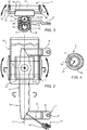
figure 2 is a schematic front view of a handle according to the invention; and -
figures 3 and 4 are cross sections along lines III-III and IV-IV, respectively, of the handle offigure 2 . - The description relates to an embodiment of a handle of the type discussed hereinafter; however, the invention disclosed in this patent application can be applied to any type of handle. Furthermore, the handle, despite being described hereinafter in relation to the inside of a commercial/heavy vehicle, can be used in any vehicle, such as a vehicle for off-road or agricultural applications.
-
Figure 1 shows the inside 1 of a vehicle, for example a commercial or heavy vehicle, comprising known elements, such as a dashboard, the steering assembly, the gear lever, etc. - The inside 1 further accommodates a
handle 2 according to the invention, which is arranged close to the opening of adoor 3 of the vehicle and is configured to be grabbed by the driver in order to help him/her climb up and reach the inside 1 of the vehicle. - The
handle 2 can have any shape, for example it can be substantially C-shaped with a constant section and comprise astraight portion 5 and a pair oftransverse portions 6 projecting perpendicularly from the ends of thestraight portion 5. - The
handle 2 further comprises fixing means 7 to fix it to aninner wall 1a of the vehicle. For example, these fixing means 7 compriseholes 8 made in the end portions of thetransverse portions 6 and configured to receive respective threaded elements configured to fix thehandle 2 to theinner wall 1a. - According to the invention, the
handle 2 further comprises charging means 10 for anelectronic device 13 and handling means 11 configured to allow the charging means 10 to be positioned on thehandle 2 in an adjustable manner. - In particular, the charging means 10 can comprise wireless charging means and comprise a
plate 12, which is configured to permit the wireless charge and is housed on adedicated support 15, which is connected to the handling means 11. - The handling means 11 can comprise a support body 14 comprising the elements described below.
- The handling means 11 can comprise first handling means configured to allow the body 14 and, hence, said charging means 10 to slide along the
straight portion 5 of thehandle 2. In particular, said first means can comprise aguide 17, which has a shape that is complementary to anouter surface 5a of thestraight portion 5 and is configured to slide on the latter with friction. - The handling means 11 can further comprise second handling means configured to allow the body 14 and, hence, said charging means 10 to rotate around the
handle 2. - In particular, the second handling means can comprise a
first hinge 20, which is configured to allow the body 14 to rotate around an axis A, which is parallel to a longitudinal axis of thestraight portion 5. For example, saidfirst hinge 20 can comprise ahousing 22, which is configured to slide around the above-mentionedguide 17. - Moreover, the second handling means can further comprise a second hinge 25, which is configured to allow the body 14 to rotate around a first axis B, which is perpendicular to the longitudinal axis of the
straight portion 5. For example, said second hinge 25 can be aball 26, which is carried by the body 14, is connected to thesupport 15 and rolls relative to ahousing 27. Thehousing 22 is advantageously connected to thehousing 27. - Moreover, the second handling means can further comprise a third hinge 30, which is configured to allow the
support 12 to rotate around a second axis C, which is perpendicular to the longitudinal axis of thestraight portion 5. In the example described herein, said third hinge 30 can be - again - theball 26, which is carried by the body 14, is connected to thesupport 15 and rolls relative to ahousing 27. - At least the
straight portion 5 of thehandle 2 advantageously comprises atubular metal core 5b, preferably with a constant and circular cross section, and acover 5c, which is fixed on the outside of thetubular core 5b. Thecover 5c can preferably be made of a plastic material, such as for example a finishing foam fixed on the outside of thetubular core 5b. - The
tubular core 5b defines aninner cavity 9 configured to house electrical connection means 31 configured to electrically connect theplate 12 to a power source, so as to allow theelectronic device 13 to be charged. Said electrical connection means 31 can advantageously be aplug 32 joining theplate 12 to a power source (not shown) of the vehicle and projecting from an opening (not shown) made in thehandle 2. - Furthermore, the
handle 2 comprises gripping means 35, which are configured to fix theelectronic device 13 on theplate 12 in a removable manner. In particular, the gripping means 35 can comprise at least a pair ofarms 36 laterally projecting relative to thesupport 15. - The
arms 36 comprise containingwalls 37 extending perpendicularly from a respective end portion thereof and facing one another. By adjusting the relative distance between thewalls 37, i.e. by adjusting the projection of thearms 36 from thesupport 15, it is possible to define a lateral fixing of theelectronic device 13. - The
handle 2 works as follows. - The user can place the
electronic device 13 on theplate 2 and fix it to the latter thanks to the gripping means 35. Indeed, by adjusting the opening defined between thewalls 37, thedevice 13 can be laterally locked. - After the
device 13 has been fixed on theplate 12, the body 14 can be moved along thehandle 5 and/or rotated around at least one of the axes A, B, C described above depending on the use of the driver of the vehicle. The friction of thehinges 20, 25, 30 and of theguide 17 relative to thesurface 5a allows the position chosen by the driver to be maintained even when the vehicle is moving. - Through a control, for example a button placed on the dashboard and/or any other known actuator, the user can activate the charge of the
device 13 and, hence, the power, by flowing through the electrical connection means 31, reaches theplate 12, which charges thedevice 13 in a known manner through induction. - Owing to the above, the advantages of a handle according to the invention are evident.
- A
handle 2 comprising charging means 10 and handling means 11 allows manufacturers to obtain a charging device that increases the space available inside the vehicle 1; as a matter of fact, no more dedicated connectors and/or supports are needed. - Furthermore, the
handle 2 disclosed above can be installed in replacement of known handles, provided that an electrical connection towards the electrical connection means 31 is subsequently established. Indeed, thehandle 2 simply needs to be fixed by means of the fixing means 7 of thearms 6, which can be sized according to the needs. - Finally, the
handle 2 according to the invention can be subjected to changes and variants, which, though, do not go beyond the scope of protection set forth in the appended claims. - For example, the charging means 10 or the moving means 11 - as well as the electrical connection means 31 or the gripping means 35 - could be manufactured in a different manner.
Claims (9)
- A handle (2) for a vehicle characterised in that it comprises charging means (10) for electronic devices (13) and handling means (11) configured for positioning said charging means (10) on said handle (2) in an adjustable manner.
- The handle according to claim 1, characterised in that said handling means (11) comprise first handling means configured to allow the movement of said charging means (10) along said handle (2) and second handling means configured for allowing the rotation of said charging means (10) around at least an axis (A; B; C) around said handle (2).
- The handle according to claim 2, characterised in that said first handling means comprise a guide (17) frictionally sliding on an external surface (5a) of said handle.
- The handle according to claim 2 or 3, characterised in that said second handling means comprise at least one of the following: a first hinge (20) configured for allowing the rotation of said charging means (10) around an axis (A) parallel to a longitudinal axis of said handle (2), a second hinge (25) configured for allowing the rotation of said charging means (10) around a first axis (B) perpendicular to said longitudinal axis of said handle (2), and a third hinge (30) configured for allowing the rotation of said charging means (10) around a second axis (C) perpendicular to said longitudinal axis of said handle (2).
- The handle according to one of the previous claims, characterised in that said charging means (10) are wireless charging means.
- The handle according to claim 5, characterised in that said wireless charging means comprise a charging plate (12) carried by a support (15) connected to said handling means (11) .
- The handle according to one of the previous claims, characterised in that it is hollow and comprises electrical connection means (31) housed inside said handle (2) configured to supply electrical energy to said charging means (10).
- The handle according to one of the previous claims, comprising a gripping means (35) configured to fix said electronic devices (13) onto said handle (2).
- The handle according to claim 8, characterised in that said gripping means (35) are carried by said support (15) and comprise a pair of arms (36) comprising end walls (37) facing one another and configured to cooperate with said electronic devices (13), the distance between said walls (37) can be varied by adjusting the length of said arms (36) in respect to said support (15).
Applications Claiming Priority (1)
| Application Number | Priority Date | Filing Date | Title |
|---|---|---|---|
| IT201700143092 | 2017-12-12 |
Publications (2)
| Publication Number | Publication Date |
|---|---|
| EP3498532A1 true EP3498532A1 (en) | 2019-06-19 |
| EP3498532B1 EP3498532B1 (en) | 2024-01-24 |
Family
ID=61656246
Family Applications (1)
| Application Number | Title | Priority Date | Filing Date |
|---|---|---|---|
| EP18212101.2A Active EP3498532B1 (en) | 2017-12-12 | 2018-12-12 | Vehicle comprising a handle |
Country Status (1)
| Country | Link |
|---|---|
| EP (1) | EP3498532B1 (en) |
Citations (3)
| Publication number | Priority date | Publication date | Assignee | Title |
|---|---|---|---|---|
| US20120080465A1 (en) * | 2010-10-05 | 2012-04-05 | Son Jae S | Removable steering wheel holder for an electronic device |
| US20120168482A1 (en) * | 2011-01-03 | 2012-07-05 | Dugan James A | Gear shift mounted accessory holder |
| US20130307470A1 (en) * | 2012-05-16 | 2013-11-21 | Honda Motor Co., Ltd. | Wireless charging structure for mobile information terminal in vehicle |
-
2018
- 2018-12-12 EP EP18212101.2A patent/EP3498532B1/en active Active
Patent Citations (3)
| Publication number | Priority date | Publication date | Assignee | Title |
|---|---|---|---|---|
| US20120080465A1 (en) * | 2010-10-05 | 2012-04-05 | Son Jae S | Removable steering wheel holder for an electronic device |
| US20120168482A1 (en) * | 2011-01-03 | 2012-07-05 | Dugan James A | Gear shift mounted accessory holder |
| US20130307470A1 (en) * | 2012-05-16 | 2013-11-21 | Honda Motor Co., Ltd. | Wireless charging structure for mobile information terminal in vehicle |
Also Published As
| Publication number | Publication date |
|---|---|
| EP3498532B1 (en) | 2024-01-24 |
Similar Documents
| Publication | Publication Date | Title |
|---|---|---|
| EP2957490A1 (en) | Straddle-type electric vehicle | |
| JP5308127B2 (en) | Power supply system | |
| US9819211B2 (en) | Wireless charging assembly for a vehicle | |
| US10017062B2 (en) | Electric charging device, electric connection device, system and method for charging a battery of a vehicle | |
| EP3041203B1 (en) | Mobile phone docking device of inside mirror | |
| DE102011005386B4 (en) | Load module and method of operating the same | |
| US9902339B2 (en) | Retractable storage apparatus | |
| US9077191B2 (en) | Charging arrangement for a vehicle | |
| DE10218505A1 (en) | Support structure with communication system for transmitting a multiplex control signal to electrical vehicle devices | |
| JP2020061923A (en) | Power supply device and plug holder | |
| EP3064395A1 (en) | Assist grip | |
| CH711964A2 (en) | Automated parking with recharging device for electric or hybrid vehicles and associated method. | |
| EP3498532B1 (en) | Vehicle comprising a handle | |
| EP4228919A4 (en) | Portable electric vehicle (ev) charging station configured for regulatory parking compliance | |
| EP3762801A4 (en) | INTEGRATED CONTROL PROCESS FOR BALANCING A TWO-WHEEL VEHICLE USING INERTIAL ORIENTATION CONTROL GYROSCOPES AND ELECTRICALLY CONTROLLED STEERING SYSTEMS | |
| KR102734724B9 (en) | Autonomous mobile tow robot and unmanned charging system for electric vehicle including the same | |
| WO2019007450A1 (en) | MOUNTING ARRANGEMENT FOR MOBILE DEVICES | |
| EP3471233B1 (en) | Charger for microphone | |
| CN111775679B (en) | Steering drive system and vehicle and kit having the same | |
| KR20180060435A (en) | Docking system and method for wireless power charging vehicle | |
| JP6666753B2 (en) | Charger adapter for in-vehicle electronic devices | |
| US20170344075A1 (en) | Electronic device dock with automated connections | |
| DE102020123251B4 (en) | Air outlet nozzle and motor vehicle | |
| EP3000668B1 (en) | Motor vehicle pedal and motor vehicle having the same | |
| CN112689572A (en) | Battery compartment |
Legal Events
| Date | Code | Title | Description |
|---|---|---|---|
| PUAI | Public reference made under article 153(3) epc to a published international application that has entered the european phase |
Free format text: ORIGINAL CODE: 0009012 |
|
| STAA | Information on the status of an ep patent application or granted ep patent |
Free format text: STATUS: THE APPLICATION HAS BEEN PUBLISHED |
|
| AK | Designated contracting states |
Kind code of ref document: A1 Designated state(s): AL AT BE BG CH CY CZ DE DK EE ES FI FR GB GR HR HU IE IS IT LI LT LU LV MC MK MT NL NO PL PT RO RS SE SI SK SM TR |
|
| AX | Request for extension of the european patent |
Extension state: BA ME |
|
| STAA | Information on the status of an ep patent application or granted ep patent |
Free format text: STATUS: REQUEST FOR EXAMINATION WAS MADE |
|
| 17P | Request for examination filed |
Effective date: 20191127 |
|
| RBV | Designated contracting states (corrected) |
Designated state(s): AL AT BE BG CH CY CZ DE DK EE ES FI FR GB GR HR HU IE IS IT LI LT LU LV MC MK MT NL NO PL PT RO RS SE SI SK SM TR |
|
| STAA | Information on the status of an ep patent application or granted ep patent |
Free format text: STATUS: EXAMINATION IS IN PROGRESS |
|
| 17Q | First examination report despatched |
Effective date: 20211020 |
|
| GRAP | Despatch of communication of intention to grant a patent |
Free format text: ORIGINAL CODE: EPIDOSNIGR1 |
|
| STAA | Information on the status of an ep patent application or granted ep patent |
Free format text: STATUS: GRANT OF PATENT IS INTENDED |
|
| INTG | Intention to grant announced |
Effective date: 20230718 |
|
| P01 | Opt-out of the competence of the unified patent court (upc) registered |
Effective date: 20230922 |
|
| GRAS | Grant fee paid |
Free format text: ORIGINAL CODE: EPIDOSNIGR3 |
|
| GRAA | (expected) grant |
Free format text: ORIGINAL CODE: 0009210 |
|
| STAA | Information on the status of an ep patent application or granted ep patent |
Free format text: STATUS: THE PATENT HAS BEEN GRANTED |
|
| AK | Designated contracting states |
Kind code of ref document: B1 Designated state(s): AL AT BE BG CH CY CZ DE DK EE ES FI FR GB GR HR HU IE IS IT LI LT LU LV MC MK MT NL NO PL PT RO RS SE SI SK SM TR |
|
| REG | Reference to a national code |
Ref country code: GB Ref legal event code: FG4D |
|
| REG | Reference to a national code |
Ref country code: CH Ref legal event code: EP |
|
| REG | Reference to a national code |
Ref country code: IE Ref legal event code: FG4D |
|
| REG | Reference to a national code |
Ref country code: DE Ref legal event code: R096 Ref document number: 602018064434 Country of ref document: DE |
|
| REG | Reference to a national code |
Ref country code: LT Ref legal event code: MG9D |
|
| REG | Reference to a national code |
Ref country code: NL Ref legal event code: MP Effective date: 20240124 |
|
| PG25 | Lapsed in a contracting state [announced via postgrant information from national office to epo] |
Ref country code: NL Free format text: LAPSE BECAUSE OF FAILURE TO SUBMIT A TRANSLATION OF THE DESCRIPTION OR TO PAY THE FEE WITHIN THE PRESCRIBED TIME-LIMIT Effective date: 20240124 |
|
| PG25 | Lapsed in a contracting state [announced via postgrant information from national office to epo] |
Ref country code: NL Free format text: LAPSE BECAUSE OF FAILURE TO SUBMIT A TRANSLATION OF THE DESCRIPTION OR TO PAY THE FEE WITHIN THE PRESCRIBED TIME-LIMIT Effective date: 20240124 |
|
| PG25 | Lapsed in a contracting state [announced via postgrant information from national office to epo] |
Ref country code: IS Free format text: LAPSE BECAUSE OF FAILURE TO SUBMIT A TRANSLATION OF THE DESCRIPTION OR TO PAY THE FEE WITHIN THE PRESCRIBED TIME-LIMIT Effective date: 20240524 |
|
| PG25 | Lapsed in a contracting state [announced via postgrant information from national office to epo] |
Ref country code: LT Free format text: LAPSE BECAUSE OF FAILURE TO SUBMIT A TRANSLATION OF THE DESCRIPTION OR TO PAY THE FEE WITHIN THE PRESCRIBED TIME-LIMIT Effective date: 20240124 |
|
| PG25 | Lapsed in a contracting state [announced via postgrant information from national office to epo] |
Ref country code: GR Free format text: LAPSE BECAUSE OF FAILURE TO SUBMIT A TRANSLATION OF THE DESCRIPTION OR TO PAY THE FEE WITHIN THE PRESCRIBED TIME-LIMIT Effective date: 20240425 |
|
| REG | Reference to a national code |
Ref country code: AT Ref legal event code: MK05 Ref document number: 1651933 Country of ref document: AT Kind code of ref document: T Effective date: 20240124 |
|
| PG25 | Lapsed in a contracting state [announced via postgrant information from national office to epo] |
Ref country code: RS Free format text: LAPSE BECAUSE OF FAILURE TO SUBMIT A TRANSLATION OF THE DESCRIPTION OR TO PAY THE FEE WITHIN THE PRESCRIBED TIME-LIMIT Effective date: 20240424 Ref country code: HR Free format text: LAPSE BECAUSE OF FAILURE TO SUBMIT A TRANSLATION OF THE DESCRIPTION OR TO PAY THE FEE WITHIN THE PRESCRIBED TIME-LIMIT Effective date: 20240124 |
|
| PG25 | Lapsed in a contracting state [announced via postgrant information from national office to epo] |
Ref country code: ES Free format text: LAPSE BECAUSE OF FAILURE TO SUBMIT A TRANSLATION OF THE DESCRIPTION OR TO PAY THE FEE WITHIN THE PRESCRIBED TIME-LIMIT Effective date: 20240124 |
|
| PG25 | Lapsed in a contracting state [announced via postgrant information from national office to epo] |
Ref country code: AT Free format text: LAPSE BECAUSE OF FAILURE TO SUBMIT A TRANSLATION OF THE DESCRIPTION OR TO PAY THE FEE WITHIN THE PRESCRIBED TIME-LIMIT Effective date: 20240124 |
|
| PG25 | Lapsed in a contracting state [announced via postgrant information from national office to epo] |
Ref country code: RS Free format text: LAPSE BECAUSE OF FAILURE TO SUBMIT A TRANSLATION OF THE DESCRIPTION OR TO PAY THE FEE WITHIN THE PRESCRIBED TIME-LIMIT Effective date: 20240424 Ref country code: NO Free format text: LAPSE BECAUSE OF FAILURE TO SUBMIT A TRANSLATION OF THE DESCRIPTION OR TO PAY THE FEE WITHIN THE PRESCRIBED TIME-LIMIT Effective date: 20240424 Ref country code: LT Free format text: LAPSE BECAUSE OF FAILURE TO SUBMIT A TRANSLATION OF THE DESCRIPTION OR TO PAY THE FEE WITHIN THE PRESCRIBED TIME-LIMIT Effective date: 20240124 Ref country code: IS Free format text: LAPSE BECAUSE OF FAILURE TO SUBMIT A TRANSLATION OF THE DESCRIPTION OR TO PAY THE FEE WITHIN THE PRESCRIBED TIME-LIMIT Effective date: 20240524 Ref country code: HR Free format text: LAPSE BECAUSE OF FAILURE TO SUBMIT A TRANSLATION OF THE DESCRIPTION OR TO PAY THE FEE WITHIN THE PRESCRIBED TIME-LIMIT Effective date: 20240124 Ref country code: GR Free format text: LAPSE BECAUSE OF FAILURE TO SUBMIT A TRANSLATION OF THE DESCRIPTION OR TO PAY THE FEE WITHIN THE PRESCRIBED TIME-LIMIT Effective date: 20240425 Ref country code: FI Free format text: LAPSE BECAUSE OF FAILURE TO SUBMIT A TRANSLATION OF THE DESCRIPTION OR TO PAY THE FEE WITHIN THE PRESCRIBED TIME-LIMIT Effective date: 20240124 Ref country code: ES Free format text: LAPSE BECAUSE OF FAILURE TO SUBMIT A TRANSLATION OF THE DESCRIPTION OR TO PAY THE FEE WITHIN THE PRESCRIBED TIME-LIMIT Effective date: 20240124 Ref country code: BG Free format text: LAPSE BECAUSE OF FAILURE TO SUBMIT A TRANSLATION OF THE DESCRIPTION OR TO PAY THE FEE WITHIN THE PRESCRIBED TIME-LIMIT Effective date: 20240124 Ref country code: AT Free format text: LAPSE BECAUSE OF FAILURE TO SUBMIT A TRANSLATION OF THE DESCRIPTION OR TO PAY THE FEE WITHIN THE PRESCRIBED TIME-LIMIT Effective date: 20240124 |
|
| PG25 | Lapsed in a contracting state [announced via postgrant information from national office to epo] |
Ref country code: PT Free format text: LAPSE BECAUSE OF FAILURE TO SUBMIT A TRANSLATION OF THE DESCRIPTION OR TO PAY THE FEE WITHIN THE PRESCRIBED TIME-LIMIT Effective date: 20240524 Ref country code: PL Free format text: LAPSE BECAUSE OF FAILURE TO SUBMIT A TRANSLATION OF THE DESCRIPTION OR TO PAY THE FEE WITHIN THE PRESCRIBED TIME-LIMIT Effective date: 20240124 |
|
| PG25 | Lapsed in a contracting state [announced via postgrant information from national office to epo] |
Ref country code: SE Free format text: LAPSE BECAUSE OF FAILURE TO SUBMIT A TRANSLATION OF THE DESCRIPTION OR TO PAY THE FEE WITHIN THE PRESCRIBED TIME-LIMIT Effective date: 20240124 Ref country code: PT Free format text: LAPSE BECAUSE OF FAILURE TO SUBMIT A TRANSLATION OF THE DESCRIPTION OR TO PAY THE FEE WITHIN THE PRESCRIBED TIME-LIMIT Effective date: 20240524 Ref country code: PL Free format text: LAPSE BECAUSE OF FAILURE TO SUBMIT A TRANSLATION OF THE DESCRIPTION OR TO PAY THE FEE WITHIN THE PRESCRIBED TIME-LIMIT Effective date: 20240124 Ref country code: LV Free format text: LAPSE BECAUSE OF FAILURE TO SUBMIT A TRANSLATION OF THE DESCRIPTION OR TO PAY THE FEE WITHIN THE PRESCRIBED TIME-LIMIT Effective date: 20240124 |
|
| PG25 | Lapsed in a contracting state [announced via postgrant information from national office to epo] |
Ref country code: DK Free format text: LAPSE BECAUSE OF FAILURE TO SUBMIT A TRANSLATION OF THE DESCRIPTION OR TO PAY THE FEE WITHIN THE PRESCRIBED TIME-LIMIT Effective date: 20240124 |
|
| PG25 | Lapsed in a contracting state [announced via postgrant information from national office to epo] |
Ref country code: SM Free format text: LAPSE BECAUSE OF FAILURE TO SUBMIT A TRANSLATION OF THE DESCRIPTION OR TO PAY THE FEE WITHIN THE PRESCRIBED TIME-LIMIT Effective date: 20240124 |
|
| PG25 | Lapsed in a contracting state [announced via postgrant information from national office to epo] |
Ref country code: CZ Free format text: LAPSE BECAUSE OF FAILURE TO SUBMIT A TRANSLATION OF THE DESCRIPTION OR TO PAY THE FEE WITHIN THE PRESCRIBED TIME-LIMIT Effective date: 20240124 Ref country code: EE Free format text: LAPSE BECAUSE OF FAILURE TO SUBMIT A TRANSLATION OF THE DESCRIPTION OR TO PAY THE FEE WITHIN THE PRESCRIBED TIME-LIMIT Effective date: 20240124 |
|
| REG | Reference to a national code |
Ref country code: DE Ref legal event code: R097 Ref document number: 602018064434 Country of ref document: DE |
|
| PG25 | Lapsed in a contracting state [announced via postgrant information from national office to epo] |
Ref country code: SK Free format text: LAPSE BECAUSE OF FAILURE TO SUBMIT A TRANSLATION OF THE DESCRIPTION OR TO PAY THE FEE WITHIN THE PRESCRIBED TIME-LIMIT Effective date: 20240124 |
|
| PG25 | Lapsed in a contracting state [announced via postgrant information from national office to epo] |
Ref country code: SM Free format text: LAPSE BECAUSE OF FAILURE TO SUBMIT A TRANSLATION OF THE DESCRIPTION OR TO PAY THE FEE WITHIN THE PRESCRIBED TIME-LIMIT Effective date: 20240124 Ref country code: SK Free format text: LAPSE BECAUSE OF FAILURE TO SUBMIT A TRANSLATION OF THE DESCRIPTION OR TO PAY THE FEE WITHIN THE PRESCRIBED TIME-LIMIT Effective date: 20240124 Ref country code: RO Free format text: LAPSE BECAUSE OF FAILURE TO SUBMIT A TRANSLATION OF THE DESCRIPTION OR TO PAY THE FEE WITHIN THE PRESCRIBED TIME-LIMIT Effective date: 20240124 Ref country code: EE Free format text: LAPSE BECAUSE OF FAILURE TO SUBMIT A TRANSLATION OF THE DESCRIPTION OR TO PAY THE FEE WITHIN THE PRESCRIBED TIME-LIMIT Effective date: 20240124 Ref country code: DK Free format text: LAPSE BECAUSE OF FAILURE TO SUBMIT A TRANSLATION OF THE DESCRIPTION OR TO PAY THE FEE WITHIN THE PRESCRIBED TIME-LIMIT Effective date: 20240124 Ref country code: CZ Free format text: LAPSE BECAUSE OF FAILURE TO SUBMIT A TRANSLATION OF THE DESCRIPTION OR TO PAY THE FEE WITHIN THE PRESCRIBED TIME-LIMIT Effective date: 20240124 |
|
| PLBE | No opposition filed within time limit |
Free format text: ORIGINAL CODE: 0009261 |
|
| STAA | Information on the status of an ep patent application or granted ep patent |
Free format text: STATUS: NO OPPOSITION FILED WITHIN TIME LIMIT |
|
| 26N | No opposition filed |
Effective date: 20241025 |
|
| PG25 | Lapsed in a contracting state [announced via postgrant information from national office to epo] |
Ref country code: SI Free format text: LAPSE BECAUSE OF FAILURE TO SUBMIT A TRANSLATION OF THE DESCRIPTION OR TO PAY THE FEE WITHIN THE PRESCRIBED TIME-LIMIT Effective date: 20240124 |
|
| PG25 | Lapsed in a contracting state [announced via postgrant information from national office to epo] |
Ref country code: MC Free format text: LAPSE BECAUSE OF FAILURE TO SUBMIT A TRANSLATION OF THE DESCRIPTION OR TO PAY THE FEE WITHIN THE PRESCRIBED TIME-LIMIT Effective date: 20240124 |
|
| REG | Reference to a national code |
Ref country code: CH Ref legal event code: PL |
|
| PG25 | Lapsed in a contracting state [announced via postgrant information from national office to epo] |
Ref country code: LU Free format text: LAPSE BECAUSE OF NON-PAYMENT OF DUE FEES Effective date: 20241212 |
|
| GBPC | Gb: european patent ceased through non-payment of renewal fee |
Effective date: 20241212 |
|
| REG | Reference to a national code |
Ref country code: BE Ref legal event code: MM Effective date: 20241231 |
|
| PG25 | Lapsed in a contracting state [announced via postgrant information from national office to epo] |
Ref country code: GB Free format text: LAPSE BECAUSE OF NON-PAYMENT OF DUE FEES Effective date: 20241212 Ref country code: BE Free format text: LAPSE BECAUSE OF NON-PAYMENT OF DUE FEES Effective date: 20241231 |
|
| PG25 | Lapsed in a contracting state [announced via postgrant information from national office to epo] |
Ref country code: CH Free format text: LAPSE BECAUSE OF NON-PAYMENT OF DUE FEES Effective date: 20241231 |
|
| PG25 | Lapsed in a contracting state [announced via postgrant information from national office to epo] |
Ref country code: IE Free format text: LAPSE BECAUSE OF NON-PAYMENT OF DUE FEES Effective date: 20241212 |
|
| PGFP | Annual fee paid to national office [announced via postgrant information from national office to epo] |
Ref country code: IT Payment date: 20251120 Year of fee payment: 8 |
|
| PGFP | Annual fee paid to national office [announced via postgrant information from national office to epo] |
Ref country code: FR Payment date: 20251223 Year of fee payment: 8 |
|
| PGFP | Annual fee paid to national office [announced via postgrant information from national office to epo] |
Ref country code: DE Payment date: 20251229 Year of fee payment: 8 |