EP3498425A1 - Laser assisted surface finishing apparatus and method - Google Patents
Laser assisted surface finishing apparatus and method Download PDFInfo
- Publication number
- EP3498425A1 EP3498425A1 EP18212085.7A EP18212085A EP3498425A1 EP 3498425 A1 EP3498425 A1 EP 3498425A1 EP 18212085 A EP18212085 A EP 18212085A EP 3498425 A1 EP3498425 A1 EP 3498425A1
- Authority
- EP
- European Patent Office
- Prior art keywords
- laser
- shot
- redirectors
- area
- finishing
- Prior art date
- Legal status (The legal status is an assumption and is not a legal conclusion. Google has not performed a legal analysis and makes no representation as to the accuracy of the status listed.)
- Granted
Links
Images
Classifications
-
- B—PERFORMING OPERATIONS; TRANSPORTING
- B24—GRINDING; POLISHING
- B24C—ABRASIVE OR RELATED BLASTING WITH PARTICULATE MATERIAL
- B24C1/00—Methods for use of abrasive blasting for producing particular effects; Use of auxiliary equipment in connection with such methods
- B24C1/10—Methods for use of abrasive blasting for producing particular effects; Use of auxiliary equipment in connection with such methods for compacting surfaces, e.g. shot-peening
-
- B—PERFORMING OPERATIONS; TRANSPORTING
- B23—MACHINE TOOLS; METAL-WORKING NOT OTHERWISE PROVIDED FOR
- B23K—SOLDERING OR UNSOLDERING; WELDING; CLADDING OR PLATING BY SOLDERING OR WELDING; CUTTING BY APPLYING HEAT LOCALLY, e.g. FLAME CUTTING; WORKING BY LASER BEAM
- B23K26/00—Working by laser beam, e.g. welding, cutting or boring
- B23K26/352—Working by laser beam, e.g. welding, cutting or boring for surface treatment
- B23K26/354—Working by laser beam, e.g. welding, cutting or boring for surface treatment by melting
-
- B—PERFORMING OPERATIONS; TRANSPORTING
- B23—MACHINE TOOLS; METAL-WORKING NOT OTHERWISE PROVIDED FOR
- B23K—SOLDERING OR UNSOLDERING; WELDING; CLADDING OR PLATING BY SOLDERING OR WELDING; CUTTING BY APPLYING HEAT LOCALLY, e.g. FLAME CUTTING; WORKING BY LASER BEAM
- B23K26/00—Working by laser beam, e.g. welding, cutting or boring
- B23K26/0093—Working by laser beam, e.g. welding, cutting or boring combined with mechanical machining or metal-working covered by other subclasses than B23K
-
- B—PERFORMING OPERATIONS; TRANSPORTING
- B23—MACHINE TOOLS; METAL-WORKING NOT OTHERWISE PROVIDED FOR
- B23P—METAL-WORKING NOT OTHERWISE PROVIDED FOR; COMBINED OPERATIONS; UNIVERSAL MACHINE TOOLS
- B23P25/00—Auxiliary treatment of workpieces, before or during machining operations, to facilitate the action of the tool or the attainment of a desired final condition of the work, e.g. relief of internal stress
- B23P25/003—Auxiliary treatment of workpieces, before or during machining operations, to facilitate the action of the tool or the attainment of a desired final condition of the work, e.g. relief of internal stress immediately preceding a cutting tool
- B23P25/006—Heating the workpiece by laser during machining
-
- C—CHEMISTRY; METALLURGY
- C21—METALLURGY OF IRON
- C21D—MODIFYING THE PHYSICAL STRUCTURE OF FERROUS METALS; GENERAL DEVICES FOR HEAT TREATMENT OF FERROUS OR NON-FERROUS METALS OR ALLOYS; MAKING METAL MALLEABLE, e.g. BY DECARBURISATION OR TEMPERING
- C21D7/00—Modifying the physical properties of iron or steel by deformation
- C21D7/02—Modifying the physical properties of iron or steel by deformation by cold working
- C21D7/04—Modifying the physical properties of iron or steel by deformation by cold working of the surface
- C21D7/06—Modifying the physical properties of iron or steel by deformation by cold working of the surface by shot-peening or the like
Definitions
- the present disclosure relates generally to a method and apparatus for finishing surfaces of a part, and more specifically to a method and apparatus for laser assisted shot peening of the surface.
- an additively manufactured component can generally have high surface roughness, porosity, and fissures in the surface of the component.
- parts susceptible to such flaws are typically subjected to one or more finishing processes.
- One finishing process used in such applications is shot peening.
- additively manufactured components comprised of certain materials can be particularly susceptible to such flaws or defects, it can also be desirable to apply similar finishing processes to components constructed according to alternative manufacturing processes including casting and milling.
- An exemplary method for finishing a surface includes, contacting a surface with a laser, rastering the laser across an area of the surface, thereby generating a local soft area, and shot peening the local soft area, thereby achieving a shot peened finish.
- Another example of any of the above described exemplary methods for finishing a surface further includes moving a shot peen nozzle relative to the surface.
- the shot peen nozzle moves independently of at least one laser redirector.
- Another example of any of the above described exemplary methods for finishing a surface further includes preventing at least one of errant shot and reflected shot from intersecting the laser.
- any of the above described exemplary methods for finishing a surface preventing the at least one of errant shot and reflected shot from intersecting the laser is at least partially achieved by disposing a shot guard between a shot peen nozzle and the laser.
- any of the above described exemplary methods for finishing a surface preventing the at least one of errant shot and reflected shot from intersecting the laser is at least partially achieved by disposing a shot guard between a shot peen nozzles and the laser and by angling the shot peen nozzle relative to the laser.
- Another example of any of the above described exemplary methods for finishing a surface further includes allowing the local soft area to partially cool for a duration after the laser has rastered across the area and before shot peening the local area.
- the duration is in the range of about 1-10 ms.
- the laser has a spot size in the range of about 100 microns to 1 mm.
- the surface is a complex surface, and a plurality of laser redirectors and a shot peen nozzle move in multiple planes.
- an apparatus for finishing a component includes at least one articulating arm including a shot peening apparatus, at least one laser source, a plurality of laser redirectors configured to redirect a laser originating from the laser source, each laser redirector in the plurality of laser redirectors being mounted to a first rail and a second rail, and a controller controllably coupled to the articulating arm and each of the rails such that output signals from the controller control a position of the articulating arm, and a position of each laser redirector in the plurality of laser redirectors.
- the laser has a spot size in the range of about 100 microns to 1 mm.
- the plurality of laser redirectors includes at least three laser redirectors.
- the plurality of laser redirectors defines at least six axis of redirection.
- the articulation arm is controllable independent of the plurality of laser redirectors.
- Another example of any of the above described apparatus for finishing a component further includes at least a second laser source.
- Additively manufactured components can include undesirable characteristics such as high surface roughnesses, undesirable porosity at or near the surface, and fissures in one or more of the exterior surfaces of the component.
- undesirable characteristics such as high surface roughnesses, undesirable porosity at or near the surface, and fissures in one or more of the exterior surfaces of the component.
- Many internal flaws can be corrected using a hot isostatic press finishing technique.
- hot isostatic pressing is ineffective at addressing surface roughness and porosity near the surface of a workpiece.
- Shot peening is one alternative that can be used to flatten or otherwise finish the surfaces of additively manufactured components
- Shot peening is a cold working process that produces a compressive residual stress layer at the surface of a component and modifies mechanical properties of metals and composites. Shot peening entails repeatedly impacting a surface with shot (e.g. round metallic, glass, or ceramic particles) with force sufficient to create plastic deformation in the surface.
- shot e.g. round metallic, glass, or ceramic particles
- additively manufactured materials can have surface conditions and flaws that shot peening at room temperature is incapable of mitigating.
- Softening the material, such as by the application of localized heat, prior to impacting the surface with the shot can reduce the resistance to deformation of the surface thereby facilitating a shot peen finishing method.
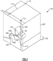
- FIG. 1 schematically illustrates an exemplary finishing apparatus 100 configured to apply a laser generated from a laser source 110 to a surface 152 of a component 150.
- the laser source 110 is fixedly mounted to a housing 102, and multiple laser redirectors 112 direct and focus the laser to the desired portion of the surface 152.
- the laser heats the surface creating a localized soft area 154 of the surface 152 that is then subjected to shot peening.
- Each of the laser redirectors 112 is mounted to two tracks 114, with the position of the laser redirector 112 sliding along the tracks 114 to which the laser redirector 112 is mounted. In the illustrated configuration, three laser redirectors 112 are utilized allowing for six axis of movement.
- laser redirectors 112 can be utilized in a practical example, depending on the degrees of movement necessary to generate the desired local soft area 154 of the surface 152.
- the number of laser redirectors 112 determines the angles that the laser can use, with more redirectors 112 allowing for more lasers. The more angles available to the lasers, the more complex the surface 152 being finished can be.
- a shot peen machine 160 including at least a nozzle 162, a hopper 164, and an articulation arm 166.
- alternative apparatuses for providing shot to the nozzle 162 can be utilized in place of the hopper 164.
- the articulation arm 166 includes multiple joints 167 that allow the articulation arm 166 to adjust the position and angle of the nozzle 162, ensuring that the nozzle 162 is maintained a predefined distance from the surface 152 of the component during the shot peening operation.
- a controller 130 such as a computer or other processing device, is connected to the apparatus 100 and controls the positions of the laser redirectors 112 and the position of the shot peen nozzle 162 during the shot peening operation.
- the shot peen nozzle 162 and the laser redirectors 112 are operated independently of each other, are not maintained in static positions relative to each other.
- the apparatus 100 can include multiple sensors, motors, processors, and the like in any configuration necessary to control the laser redirectors 112, the shot peen machine 160 and any other automated components according to any known method.
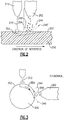
- Figure 2 schematically illustrates a view of a single surface of a component being finished within a finishing apparatus, such as the apparatus 100.
- a laser 210 is redirected by a laser redirector 212, and contacts a surface 252 of the component 250.
- the surface area of the contact between the laser 210 and the surface 252 is referred to as a spot size.
- the spot size can range from .01 mm to 1 mm, with the size of the spot and the power of the laser affecting the magnitude of heat imparted into the surface as the laser 210 is rastered across the surface 252.
- the laser 210 is rastered across a targeted area of the surface 252, thereby generating a localized soft area 254.
- the localized soft area 254 is a portion of the surface 252 that extends into the component and has been heated by the laser 210. Heating to create the localized soft area increases the susceptibility of the localized soft area 254 to deformation from shot peening impacts, thereby increasing the effectiveness of the shot peening.
- the laser 210 heats the localized soft area 254 to a sufficient level to allow for the increased deformation of the surface 252, without melting the surface 252 and creating a melt pool, and without heating the entire thickness of the surface 252.
- the depth into the surface 252 of the localized soft area 254 is greatest at the position of the laser spot, and decreases in depth as the localized soft area 254 cools.
- a time delay is implemented between when a portion of the localized soft area 254 is initially rastered by the laser 210 and when the portion is subjected to the shot peening.
- the time delay can be in the range of 1 to 10 ms.
- the localized soft area 254 is allowed to cool convectively.
- alternative cooling techniques could be utilized to similar effect.
- the shot peening itself can actively cool the localized soft area 254.
- the shot 246' During operation of the apparatus 100, after the shot 246 impacts the soft area 254, the shot 246' reflects in random directions. In addition, in order to improve the results of the shot peening process, the shot 246 exits the nozzle in a semi random spray. If errant shot 246', or reflected shot 246', intercepts the laser 210, contact between the laser 210 and the surface 252 is temporarily interrupted. This interruption can potentially result in insufficiently softened portions of the localized soft area 254. In order to prevent errant shot 246' and reflected shot 246' from interfering with the laser 210, a shot guard 264 is mounted to the nozzle 262.
- the shot guard extends from the nozzle 262 toward the surface 252 and blocks reflected and errant shot 246'.
- the nozzle 262 can be angled, relative to the laser 210, such that shot 246 from the nozzle 262 is directed away from the laser 210 when the shot 246' is reflected off the surface 252.
- the nozzle 262 can be angled and a shot guard 264 can be incorporated for redundant protection.
- Figure 3 schematically illustrates an alternate component 300 being finished in a finishing apparatus, such as the apparatus 100 of Figure 1 .
- the alternate component 300 includes a single curved surface, although it is envisioned that surfaces include more complex curvature could be utilized in a similar manner, subject to the capabilities of the shot peen nozzle.
- the laser 310 can travel along substantially complex surfaces 352, generating the desired localized soft area 354.
- complex surfaces refers to any surface including a substantially varied radius of curvature across the surface. In such an example the localized soft area 354, and the laser 310 heating, function substantially similarly to the example described above with regards to Figure 2 .
- the creation of the localized soft area 254, 354 via the application of the laser energy, renders the localized soft area 254, 354 more ductile, thereby allowing the shot peen to more easily close or flatten imperfections in the surface at the localized soft area.
- the shot peen flattens high spots, collapses porosity, and closes fissures that can result at or near the surface in an additively manufactured component.
- the shot 246, 346 can facilitate cooling of the localized soft area 254, 354 by carrying away heat in addition to the convective cooling, returning the component to ambient temperatures relatively quickly.
Landscapes
- Engineering & Computer Science (AREA)
- Mechanical Engineering (AREA)
- Physics & Mathematics (AREA)
- Optics & Photonics (AREA)
- Plasma & Fusion (AREA)
- Laser Beam Processing (AREA)
Abstract
Description
- The present disclosure relates generally to a method and apparatus for finishing surfaces of a part, and more specifically to a method and apparatus for laser assisted shot peening of the surface.
- Various techniques for manufacturing components, such as those used in complex machinery, can result in flaws or defects at or near the surface of the manufactured component. By way of example, an additively manufactured component can generally have high surface roughness, porosity, and fissures in the surface of the component. In order to reduce the impact of, or remove the presence of, the flaws or defects, parts susceptible to such flaws are typically subjected to one or more finishing processes. One finishing process used in such applications is shot peening.
- While additively manufactured components comprised of certain materials can be particularly susceptible to such flaws or defects, it can also be desirable to apply similar finishing processes to components constructed according to alternative manufacturing processes including casting and milling.
- An exemplary method for finishing a surface includes, contacting a surface with a laser, rastering the laser across an area of the surface, thereby generating a local soft area, and shot peening the local soft area, thereby achieving a shot peened finish.
- In another example of the above described exemplary method for finishing a surface rastering the surface comprises moving at least one laser redirector relative to the surface.
- Another example of any of the above described exemplary methods for finishing a surface further includes moving a shot peen nozzle relative to the surface.
- In another example of any of the above described exemplary methods for finishing a surface the shot peen nozzle moves independently of at least one laser redirector.
- Another example of any of the above described exemplary methods for finishing a surface further includes preventing at least one of errant shot and reflected shot from intersecting the laser.
- In another example of any of the above described exemplary methods for finishing a surface preventing the at least one of errant shot and reflected shot from intersecting the laser is at least partially achieved by disposing a shot guard between a shot peen nozzle and the laser.
- In another example of any of the above described exemplary methods for finishing a surface preventing the at least one of errant shot and reflected shot from intersecting the laser is at least partially achieved by angling the shot peen nozzle relative to the laser.
- In another example of any of the above described exemplary methods for finishing a surface preventing the at least one of errant shot and reflected shot from intersecting the laser is at least partially achieved by disposing a shot guard between a shot peen nozzles and the laser and by angling the shot peen nozzle relative to the laser.
- Another example of any of the above described exemplary methods for finishing a surface further includes allowing the local soft area to partially cool for a duration after the laser has rastered across the area and before shot peening the local area.
- In another example of any of the above described exemplary methods for finishing a surface the duration is in the range of about 1-10 ms.
- In another example of any of the above described exemplary methods for finishing a surface the laser has a spot size in the range of about 100 microns to 1 mm.
- In another example of any of the above described exemplary methods for finishing a surface the surface is a complex surface, and a plurality of laser redirectors and a shot peen nozzle move in multiple planes.
- In one exemplary embodiment an apparatus for finishing a component includes at least one articulating arm including a shot peening apparatus, at least one laser source, a plurality of laser redirectors configured to redirect a laser originating from the laser source, each laser redirector in the plurality of laser redirectors being mounted to a first rail and a second rail, and a controller controllably coupled to the articulating arm and each of the rails such that output signals from the controller control a position of the articulating arm, and a position of each laser redirector in the plurality of laser redirectors.
- In another example of the above described apparatus for finishing a component the laser has a spot size in the range of about 100 microns to 1 mm.
- In another example of any of the above described apparatus for finishing a component the plurality of laser redirectors includes at least three laser redirectors.
- In another example of any of the above described apparatus for finishing a component the plurality of laser redirectors defines at least six axis of redirection.
- In another example of any of the above described apparatus for finishing a component the articulation arm is controllable independent of the plurality of laser redirectors.
- Another example of any of the above described apparatus for finishing a component further includes at least a second laser source.
- These and other features of the present invention can be best understood from the following specification and drawings, the following of which is a brief description.
-
-
Figure 1 illustrates a schematic view of a component finishing apparatus. -
Figure 2 schematically illustrates a view of a simple surface of a component during a finishing process. -
Figure 3 schematically illustrates a schematic view of a curved surface of a component being finished. - Additively manufactured components, as well as some components manufactured using other manufacturing techniques, can include undesirable characteristics such as high surface roughnesses, undesirable porosity at or near the surface, and fissures in one or more of the exterior surfaces of the component. Many internal flaws can be corrected using a hot isostatic press finishing technique. However, hot isostatic pressing is ineffective at addressing surface roughness and porosity near the surface of a workpiece.
- Shot peening is one alternative that can be used to flatten or otherwise finish the surfaces of additively manufactured components Shot peening is a cold working process that produces a compressive residual stress layer at the surface of a component and modifies mechanical properties of metals and composites. Shot peening entails repeatedly impacting a surface with shot (e.g. round metallic, glass, or ceramic particles) with force sufficient to create plastic deformation in the surface.
- However, in some cases additively manufactured materials can have surface conditions and flaws that shot peening at room temperature is incapable of mitigating. Softening the material, such as by the application of localized heat, prior to impacting the surface with the shot can reduce the resistance to deformation of the surface thereby facilitating a shot peen finishing method.
- Further, because shot peening involves repeatedly impacting a surface with multiple hard spheroids to generate plastic deformation in the surface, it is necessary that the surface of the material be more susceptible to deformation than the spheroids themselves. If the surface is less susceptible to the deformation, then the spheroids will deform and there will be relatively little impact on the surface itself. Some materials utilized in additively manufactured components and in similar components are less susceptible to deformation at room temperature than the shot from the shot peening process.
-
Figure 1 schematically illustrates anexemplary finishing apparatus 100 configured to apply a laser generated from alaser source 110 to asurface 152 of acomponent 150. Thelaser source 110 is fixedly mounted to ahousing 102, andmultiple laser redirectors 112 direct and focus the laser to the desired portion of thesurface 152. The laser heats the surface creating a localizedsoft area 154 of thesurface 152 that is then subjected to shot peening. Each of thelaser redirectors 112 is mounted to twotracks 114, with the position of thelaser redirector 112 sliding along thetracks 114 to which thelaser redirector 112 is mounted. In the illustrated configuration, threelaser redirectors 112 are utilized allowing for six axis of movement. It is appreciated that more, or less,laser redirectors 112 can be utilized in a practical example, depending on the degrees of movement necessary to generate the desired localsoft area 154 of thesurface 152. The number oflaser redirectors 112 determines the angles that the laser can use, withmore redirectors 112 allowing for more lasers. The more angles available to the lasers, the more complex thesurface 152 being finished can be. - Also included within the
apparatus 100 is a shot peen machine 160 including at least anozzle 162, ahopper 164, and anarticulation arm 166. In alternative examples, alternative apparatuses for providing shot to thenozzle 162 can be utilized in place of thehopper 164. Thearticulation arm 166 includesmultiple joints 167 that allow thearticulation arm 166 to adjust the position and angle of thenozzle 162, ensuring that thenozzle 162 is maintained a predefined distance from thesurface 152 of the component during the shot peening operation. - A
controller 130, such as a computer or other processing device, is connected to theapparatus 100 and controls the positions of thelaser redirectors 112 and the position of theshot peen nozzle 162 during the shot peening operation. Theshot peen nozzle 162 and thelaser redirectors 112 are operated independently of each other, are not maintained in static positions relative to each other. Theapparatus 100 can include multiple sensors, motors, processors, and the like in any configuration necessary to control thelaser redirectors 112, the shot peen machine 160 and any other automated components according to any known method. - With continued reference to
Figure 1 , and with like numerals indicating like elements,Figure 2 schematically illustrates a view of a single surface of a component being finished within a finishing apparatus, such as theapparatus 100. Initially a laser 210 is redirected by alaser redirector 212, and contacts asurface 252 of thecomponent 250. The surface area of the contact between the laser 210 and thesurface 252 is referred to as a spot size. In some practical implementations the spot size can range from .01 mm to 1 mm, with the size of the spot and the power of the laser affecting the magnitude of heat imparted into the surface as the laser 210 is rastered across thesurface 252. - The laser 210 is rastered across a targeted area of the
surface 252, thereby generating a localizedsoft area 254. The localizedsoft area 254 is a portion of thesurface 252 that extends into the component and has been heated by the laser 210. Heating to create the localized soft area increases the susceptibility of the localizedsoft area 254 to deformation from shot peening impacts, thereby increasing the effectiveness of the shot peening. - The laser 210 heats the localized
soft area 254 to a sufficient level to allow for the increased deformation of thesurface 252, without melting thesurface 252 and creating a melt pool, and without heating the entire thickness of thesurface 252. The depth into thesurface 252 of the localizedsoft area 254 is greatest at the position of the laser spot, and decreases in depth as the localizedsoft area 254 cools. In order to ensure that a desired depth of the localizedsoft area 254 is present when the localizedsoft area 254 is subject to the shot peening from the nozzle 262 a time delay is implemented between when a portion of the localizedsoft area 254 is initially rastered by the laser 210 and when the portion is subjected to the shot peening. In some examples, the time delay can be in the range of 1 to 10 ms. - Once subjected to the shot peening, the localized
soft area 254 is allowed to cool convectively. In alternative examples, alternative cooling techniques could be utilized to similar effect. In yet further examples, the shot peening itself can actively cool the localizedsoft area 254. - During operation of the
apparatus 100, after theshot 246 impacts thesoft area 254, the shot 246' reflects in random directions. In addition, in order to improve the results of the shot peening process, theshot 246 exits the nozzle in a semi random spray. If errant shot 246', or reflected shot 246', intercepts the laser 210, contact between the laser 210 and thesurface 252 is temporarily interrupted. This interruption can potentially result in insufficiently softened portions of the localizedsoft area 254. In order to prevent errant shot 246' and reflected shot 246' from interfering with the laser 210, a shot guard 264 is mounted to thenozzle 262. The shot guard extends from thenozzle 262 toward thesurface 252 and blocks reflected and errant shot 246'. In alternative examples, thenozzle 262 can be angled, relative to the laser 210, such that shot 246 from thenozzle 262 is directed away from the laser 210 when the shot 246' is reflected off thesurface 252. In yet further alternate examples, thenozzle 262 can be angled and a shot guard 264 can be incorporated for redundant protection. - With continued reference to
Figures 1 and2, Figure 3 schematically illustrates analternate component 300 being finished in a finishing apparatus, such as theapparatus 100 ofFigure 1 . Thealternate component 300 includes a single curved surface, although it is envisioned that surfaces include more complex curvature could be utilized in a similar manner, subject to the capabilities of the shot peen nozzle. As thelaser 310 is redirected independent of the articulation of theshot peen nozzle 362 thelaser 310 can travel along substantiallycomplex surfaces 352, generating the desired localizedsoft area 354. As used herein, complex surfaces refers to any surface including a substantially varied radius of curvature across the surface. In such an example the localizedsoft area 354, and thelaser 310 heating, function substantially similarly to the example described above with regards toFigure 2 . - With reference to
Figures 1-3 , the creation of the localizedsoft area soft area shot soft area - While illustrated in the exemplary embodiment of
Figures 1-3 as including only a single laser source, it should be appreciated that multiple laser sources could be used to further enable rastering across distinct angles and complex curves. - It is further understood that any of the above described concepts can be used alone or in combination with any or all of the other above described concepts. Although an embodiment of this invention has been disclosed, a worker of ordinary skill in this art would recognize that certain modifications would come within the scope of this invention. For that reason, the following claims should be studied to determine the true scope and content of this invention.
Claims (15)
- A method for finishing a surface comprising:contacting a surface with a laser;rastering the laser across an area of the surface, thereby generating a local soft area; andshot peening the local soft area, thereby achieving a shot peened finish.
- The method of claim 1, wherein rastering the surface comprises moving at least one laser redirector relative to the surface.
- The method of claim 1 or 2, further comprising moving a shot peen nozzle relative to the surface.
- The method of claim 3, wherein the shot peen nozzle moves independently of at least one laser redirector.
- The method of any preceding claim, further comprising preventing at least one of errant shot and reflected shot from intersecting the laser.
- The method of claim 5, wherein preventing the at least one of errant shot and reflected shot from intersecting the laser is at least partially achieved by disposing a shot guard between a shot peen nozzle and the laser, and/or by angling the shot peen nozzle relative to the laser.
- The method of any preceding claim, further comprising allowing the local soft area to partially cool for a duration after the laser has rastered across the area and before shot peening the local area.
- The method of claim 7, wherein the duration is in the range of about 1-10 ms.
- The method of any preceding claim, wherein the surface is a complex surface, and a plurality of laser redirectors and a shot peen nozzle move in multiple planes.
- An apparatus for finishing a component comprising:at least one articulating arm including a shot peening apparatus;at least one laser source;a plurality of laser redirectors configured to redirect a laser originating from the laser source, each laser redirector in the plurality of laser redirectors being mounted to a first rail and a second rail; anda controller controllably coupled to the articulating arm and each of the rails such that output signals from the controller control a position of the articulating arm, and a position of each laser redirector in the plurality of laser redirectors.
- The apparatus of claim 10 or the method of any one of claim 1-9, wherein the laser has a spot size in the range of about 100 microns to 1 mm.
- The apparatus of claim 10 or 11, wherein the plurality of laser redirectors includes at least three laser redirectors.
- The apparatus of any one of claims 10-12, wherein the plurality of laser redirectors defines at least six axis of redirection.
- The apparatus of any one of claims 10-13, wherein the articulation arm is controllable independent of the plurality of laser redirectors.
- The apparatus of any one of claims 10-14, further comprising at least a second laser source.
Applications Claiming Priority (1)
| Application Number | Priority Date | Filing Date | Title |
|---|---|---|---|
| US15/843,312 US10807214B2 (en) | 2017-12-15 | 2017-12-15 | Laser assisted surface finishing apparatus and method |
Publications (2)
| Publication Number | Publication Date |
|---|---|
| EP3498425A1 true EP3498425A1 (en) | 2019-06-19 |
| EP3498425B1 EP3498425B1 (en) | 2021-09-08 |
Family
ID=64665198
Family Applications (1)
| Application Number | Title | Priority Date | Filing Date |
|---|---|---|---|
| EP18212085.7A Active EP3498425B1 (en) | 2017-12-15 | 2018-12-12 | Laser assisted surface finishing apparatus and method |
Country Status (2)
| Country | Link |
|---|---|
| US (1) | US10807214B2 (en) |
| EP (1) | EP3498425B1 (en) |
Families Citing this family (4)
| Publication number | Priority date | Publication date | Assignee | Title |
|---|---|---|---|---|
| JP7409245B2 (en) * | 2020-07-13 | 2024-01-09 | 新東工業株式会社 | Surface treatment method |
| JP7635579B2 (en) * | 2021-02-26 | 2025-02-26 | 新東工業株式会社 | Surface treatment method and surface treatment system |
| CN113122701B (en) * | 2021-03-22 | 2022-09-27 | 首钢集团有限公司 | Method and device for preparing soft area by thermoforming part |
| CN114762914A (en) * | 2022-05-27 | 2022-07-19 | 南京航空航天大学 | Laser and ultrasonic shot blasting composite processing device and processing method |
Citations (10)
| Publication number | Priority date | Publication date | Assignee | Title |
|---|---|---|---|---|
| US5174143A (en) * | 1991-11-05 | 1992-12-29 | Mcdonnell Douglas Corporation | Surface densification of porous materials |
| JPH0551629A (en) * | 1991-08-26 | 1993-03-02 | Brother Ind Ltd | Hardening method for surface |
| US5302218A (en) * | 1991-09-24 | 1994-04-12 | Mazda Motor Corporation | Surface reforming method of aluminum alloy members |
| JPH10286774A (en) * | 1997-04-15 | 1998-10-27 | Mitsubishi Heavy Ind Ltd | Coating processing method and device |
| US6183348B1 (en) * | 1998-04-07 | 2001-02-06 | Bechtel Bwxt Idaho, Llc | Methods and apparatuses for cutting, abrading, and drilling |
| US20080213978A1 (en) * | 2007-03-03 | 2008-09-04 | Dynatex | Debris management for wafer singulation |
| US7887393B2 (en) * | 2007-04-25 | 2011-02-15 | Fuji Manufacturing Co., Ltd. | Moving mechanism for blast gun for blasting machine |
| CN102896585A (en) * | 2012-10-18 | 2013-01-30 | 山东雷帕得弹簧有限公司 | Shot blasting process for producing high-strength and high-stress steel plate spring |
| CN203393190U (en) * | 2013-07-09 | 2014-01-15 | 南京中科煜宸激光技术有限公司 | Laser ultrasonic shot blasting quenching combined machining device |
| CA3014855A1 (en) * | 2016-02-19 | 2017-08-24 | Safran | Method and apparatus for manufacturing a part using successive depositions of layers |
-
2017
- 2017-12-15 US US15/843,312 patent/US10807214B2/en active Active
-
2018
- 2018-12-12 EP EP18212085.7A patent/EP3498425B1/en active Active
Patent Citations (10)
| Publication number | Priority date | Publication date | Assignee | Title |
|---|---|---|---|---|
| JPH0551629A (en) * | 1991-08-26 | 1993-03-02 | Brother Ind Ltd | Hardening method for surface |
| US5302218A (en) * | 1991-09-24 | 1994-04-12 | Mazda Motor Corporation | Surface reforming method of aluminum alloy members |
| US5174143A (en) * | 1991-11-05 | 1992-12-29 | Mcdonnell Douglas Corporation | Surface densification of porous materials |
| JPH10286774A (en) * | 1997-04-15 | 1998-10-27 | Mitsubishi Heavy Ind Ltd | Coating processing method and device |
| US6183348B1 (en) * | 1998-04-07 | 2001-02-06 | Bechtel Bwxt Idaho, Llc | Methods and apparatuses for cutting, abrading, and drilling |
| US20080213978A1 (en) * | 2007-03-03 | 2008-09-04 | Dynatex | Debris management for wafer singulation |
| US7887393B2 (en) * | 2007-04-25 | 2011-02-15 | Fuji Manufacturing Co., Ltd. | Moving mechanism for blast gun for blasting machine |
| CN102896585A (en) * | 2012-10-18 | 2013-01-30 | 山东雷帕得弹簧有限公司 | Shot blasting process for producing high-strength and high-stress steel plate spring |
| CN203393190U (en) * | 2013-07-09 | 2014-01-15 | 南京中科煜宸激光技术有限公司 | Laser ultrasonic shot blasting quenching combined machining device |
| CA3014855A1 (en) * | 2016-02-19 | 2017-08-24 | Safran | Method and apparatus for manufacturing a part using successive depositions of layers |
Non-Patent Citations (1)
| Title |
|---|
| M. SCHILLING-PRAETZEL: "Influence of Temperature of Shot Peening on Fatigue Life", N/A, 17 September 1993 (1993-09-17), pages 227 - 238, XP055326453 * |
Also Published As
| Publication number | Publication date |
|---|---|
| US10807214B2 (en) | 2020-10-20 |
| US20190184521A1 (en) | 2019-06-20 |
| EP3498425B1 (en) | 2021-09-08 |
Similar Documents
| Publication | Publication Date | Title |
|---|---|---|
| EP3498425B1 (en) | Laser assisted surface finishing apparatus and method | |
| Wei et al. | High speed, high power density laser-assisted machining of Al-SiC metal matrix composite with significant increase in productivity and surface quality | |
| CN109746441B (en) | A composite processing method for laser additive manufacturing assisted by laser shock strengthening | |
| EP3229994B1 (en) | Additive manufacturing and integrated impact post-treatment | |
| JP5886977B2 (en) | Method and tool for hot forming and press-curing coated steel sheet workpieces, in particular galvanized sheet steel workpieces | |
| CN101605914B (en) | Method and apparatus for case hardening of components of complex shape | |
| EP2340143B1 (en) | Inert gas cover system for laser welding with a base and wall having an opening | |
| CN101011777A (en) | Method and apparatus of forming cut deal laser prestress composite shot blasting | |
| Brecher et al. | Laser-assisted milling of advanced materials | |
| US11267100B2 (en) | Plasma assisted surface finishing apparatus and method | |
| CN109530910A (en) | A method of changing product surface roughness using laser | |
| CN108500468A (en) | A kind of method of curved profile laser deburring | |
| CN108817699B (en) | Method for cutting two-phase composite material by using ultrafast laser | |
| KR20160044431A (en) | Method for Blunting Sharp Edges of Glass Objects | |
| CN116568644A (en) | Ceramic cutting method and device | |
| CN111005022B (en) | Method for preparing high-hardness iron-based coating on surface of beryllium bronze copper roller by utilizing three lasers in synergy mode | |
| EP2855719B1 (en) | Deep laser peening | |
| US11458572B2 (en) | Laser smoothing | |
| KR101574934B1 (en) | Chamfering method for brittle material | |
| CN101678510B (en) | Method for producing component using asymmetrical energy input along parting or predetermined breaking line | |
| KR20180039213A (en) | Laser Deposition Apparatus Having Heating Unit | |
| CA2480322A1 (en) | Apparatus and method for forming a weld joint having improved physical properties | |
| Hatamleh et al. | Finite element study of laser peening on selective laser melted A357 aluminum alloy during tension test | |
| CN112338814B (en) | Composite shot peening method of turbine disk | |
| KR20130076607A (en) | Double peening apparatus and double peening method using it |
Legal Events
| Date | Code | Title | Description |
|---|---|---|---|
| PUAI | Public reference made under article 153(3) epc to a published international application that has entered the european phase |
Free format text: ORIGINAL CODE: 0009012 |
|
| STAA | Information on the status of an ep patent application or granted ep patent |
Free format text: STATUS: THE APPLICATION HAS BEEN PUBLISHED |
|
| AK | Designated contracting states |
Kind code of ref document: A1 Designated state(s): AL AT BE BG CH CY CZ DE DK EE ES FI FR GB GR HR HU IE IS IT LI LT LU LV MC MK MT NL NO PL PT RO RS SE SI SK SM TR |
|
| AX | Request for extension of the european patent |
Extension state: BA ME |
|
| STAA | Information on the status of an ep patent application or granted ep patent |
Free format text: STATUS: REQUEST FOR EXAMINATION WAS MADE |
|
| 17P | Request for examination filed |
Effective date: 20191219 |
|
| RBV | Designated contracting states (corrected) |
Designated state(s): AL AT BE BG CH CY CZ DE DK EE ES FI FR GB GR HR HU IE IS IT LI LT LU LV MC MK MT NL NO PL PT RO RS SE SI SK SM TR |
|
| STAA | Information on the status of an ep patent application or granted ep patent |
Free format text: STATUS: EXAMINATION IS IN PROGRESS |
|
| 17Q | First examination report despatched |
Effective date: 20200204 |
|
| GRAP | Despatch of communication of intention to grant a patent |
Free format text: ORIGINAL CODE: EPIDOSNIGR1 |
|
| RAP1 | Party data changed (applicant data changed or rights of an application transferred) |
Owner name: RAYTHEON TECHNOLOGIES CORPORATION |
|
| STAA | Information on the status of an ep patent application or granted ep patent |
Free format text: STATUS: GRANT OF PATENT IS INTENDED |
|
| RIC1 | Information provided on ipc code assigned before grant |
Ipc: C21D 7/06 20060101ALN20210305BHEP Ipc: B23P 25/00 20060101ALN20210305BHEP Ipc: B23K 26/00 20140101ALN20210305BHEP Ipc: B24C 1/10 20060101AFI20210305BHEP |
|
| INTG | Intention to grant announced |
Effective date: 20210325 |
|
| GRAS | Grant fee paid |
Free format text: ORIGINAL CODE: EPIDOSNIGR3 |
|
| GRAA | (expected) grant |
Free format text: ORIGINAL CODE: 0009210 |
|
| STAA | Information on the status of an ep patent application or granted ep patent |
Free format text: STATUS: THE PATENT HAS BEEN GRANTED |
|
| AK | Designated contracting states |
Kind code of ref document: B1 Designated state(s): AL AT BE BG CH CY CZ DE DK EE ES FI FR GB GR HR HU IE IS IT LI LT LU LV MC MK MT NL NO PL PT RO RS SE SI SK SM TR |
|
| REG | Reference to a national code |
Ref country code: GB Ref legal event code: FG4D |
|
| REG | Reference to a national code |
Ref country code: AT Ref legal event code: REF Ref document number: 1428150 Country of ref document: AT Kind code of ref document: T Effective date: 20210915 Ref country code: CH Ref legal event code: EP |
|
| REG | Reference to a national code |
Ref country code: IE Ref legal event code: FG4D |
|
| REG | Reference to a national code |
Ref country code: DE Ref legal event code: R096 Ref document number: 602018023183 Country of ref document: DE |
|
| REG | Reference to a national code |
Ref country code: LT Ref legal event code: MG9D |
|
| REG | Reference to a national code |
Ref country code: NL Ref legal event code: MP Effective date: 20210908 |
|
| PG25 | Lapsed in a contracting state [announced via postgrant information from national office to epo] |
Ref country code: HR Free format text: LAPSE BECAUSE OF FAILURE TO SUBMIT A TRANSLATION OF THE DESCRIPTION OR TO PAY THE FEE WITHIN THE PRESCRIBED TIME-LIMIT Effective date: 20210908 Ref country code: ES Free format text: LAPSE BECAUSE OF FAILURE TO SUBMIT A TRANSLATION OF THE DESCRIPTION OR TO PAY THE FEE WITHIN THE PRESCRIBED TIME-LIMIT Effective date: 20210908 Ref country code: FI Free format text: LAPSE BECAUSE OF FAILURE TO SUBMIT A TRANSLATION OF THE DESCRIPTION OR TO PAY THE FEE WITHIN THE PRESCRIBED TIME-LIMIT Effective date: 20210908 Ref country code: SE Free format text: LAPSE BECAUSE OF FAILURE TO SUBMIT A TRANSLATION OF THE DESCRIPTION OR TO PAY THE FEE WITHIN THE PRESCRIBED TIME-LIMIT Effective date: 20210908 Ref country code: RS Free format text: LAPSE BECAUSE OF FAILURE TO SUBMIT A TRANSLATION OF THE DESCRIPTION OR TO PAY THE FEE WITHIN THE PRESCRIBED TIME-LIMIT Effective date: 20210908 Ref country code: BG Free format text: LAPSE BECAUSE OF FAILURE TO SUBMIT A TRANSLATION OF THE DESCRIPTION OR TO PAY THE FEE WITHIN THE PRESCRIBED TIME-LIMIT Effective date: 20211208 Ref country code: LT Free format text: LAPSE BECAUSE OF FAILURE TO SUBMIT A TRANSLATION OF THE DESCRIPTION OR TO PAY THE FEE WITHIN THE PRESCRIBED TIME-LIMIT Effective date: 20210908 Ref country code: NO Free format text: LAPSE BECAUSE OF FAILURE TO SUBMIT A TRANSLATION OF THE DESCRIPTION OR TO PAY THE FEE WITHIN THE PRESCRIBED TIME-LIMIT Effective date: 20211208 |
|
| REG | Reference to a national code |
Ref country code: AT Ref legal event code: MK05 Ref document number: 1428150 Country of ref document: AT Kind code of ref document: T Effective date: 20210908 |
|
| PG25 | Lapsed in a contracting state [announced via postgrant information from national office to epo] |
Ref country code: LV Free format text: LAPSE BECAUSE OF FAILURE TO SUBMIT A TRANSLATION OF THE DESCRIPTION OR TO PAY THE FEE WITHIN THE PRESCRIBED TIME-LIMIT Effective date: 20210908 Ref country code: GR Free format text: LAPSE BECAUSE OF FAILURE TO SUBMIT A TRANSLATION OF THE DESCRIPTION OR TO PAY THE FEE WITHIN THE PRESCRIBED TIME-LIMIT Effective date: 20211209 |
|
| PG25 | Lapsed in a contracting state [announced via postgrant information from national office to epo] |
Ref country code: AT Free format text: LAPSE BECAUSE OF FAILURE TO SUBMIT A TRANSLATION OF THE DESCRIPTION OR TO PAY THE FEE WITHIN THE PRESCRIBED TIME-LIMIT Effective date: 20210908 |
|
| PG25 | Lapsed in a contracting state [announced via postgrant information from national office to epo] |
Ref country code: IS Free format text: LAPSE BECAUSE OF FAILURE TO SUBMIT A TRANSLATION OF THE DESCRIPTION OR TO PAY THE FEE WITHIN THE PRESCRIBED TIME-LIMIT Effective date: 20220108 Ref country code: SM Free format text: LAPSE BECAUSE OF FAILURE TO SUBMIT A TRANSLATION OF THE DESCRIPTION OR TO PAY THE FEE WITHIN THE PRESCRIBED TIME-LIMIT Effective date: 20210908 Ref country code: SK Free format text: LAPSE BECAUSE OF FAILURE TO SUBMIT A TRANSLATION OF THE DESCRIPTION OR TO PAY THE FEE WITHIN THE PRESCRIBED TIME-LIMIT Effective date: 20210908 Ref country code: RO Free format text: LAPSE BECAUSE OF FAILURE TO SUBMIT A TRANSLATION OF THE DESCRIPTION OR TO PAY THE FEE WITHIN THE PRESCRIBED TIME-LIMIT Effective date: 20210908 Ref country code: PT Free format text: LAPSE BECAUSE OF FAILURE TO SUBMIT A TRANSLATION OF THE DESCRIPTION OR TO PAY THE FEE WITHIN THE PRESCRIBED TIME-LIMIT Effective date: 20220110 Ref country code: PL Free format text: LAPSE BECAUSE OF FAILURE TO SUBMIT A TRANSLATION OF THE DESCRIPTION OR TO PAY THE FEE WITHIN THE PRESCRIBED TIME-LIMIT Effective date: 20210908 Ref country code: NL Free format text: LAPSE BECAUSE OF FAILURE TO SUBMIT A TRANSLATION OF THE DESCRIPTION OR TO PAY THE FEE WITHIN THE PRESCRIBED TIME-LIMIT Effective date: 20210908 Ref country code: EE Free format text: LAPSE BECAUSE OF FAILURE TO SUBMIT A TRANSLATION OF THE DESCRIPTION OR TO PAY THE FEE WITHIN THE PRESCRIBED TIME-LIMIT Effective date: 20210908 Ref country code: CZ Free format text: LAPSE BECAUSE OF FAILURE TO SUBMIT A TRANSLATION OF THE DESCRIPTION OR TO PAY THE FEE WITHIN THE PRESCRIBED TIME-LIMIT Effective date: 20210908 Ref country code: AL Free format text: LAPSE BECAUSE OF FAILURE TO SUBMIT A TRANSLATION OF THE DESCRIPTION OR TO PAY THE FEE WITHIN THE PRESCRIBED TIME-LIMIT Effective date: 20210908 |
|
| REG | Reference to a national code |
Ref country code: DE Ref legal event code: R097 Ref document number: 602018023183 Country of ref document: DE |
|
| PLBE | No opposition filed within time limit |
Free format text: ORIGINAL CODE: 0009261 |
|
| STAA | Information on the status of an ep patent application or granted ep patent |
Free format text: STATUS: NO OPPOSITION FILED WITHIN TIME LIMIT |
|
| PG25 | Lapsed in a contracting state [announced via postgrant information from national office to epo] |
Ref country code: MC Free format text: LAPSE BECAUSE OF FAILURE TO SUBMIT A TRANSLATION OF THE DESCRIPTION OR TO PAY THE FEE WITHIN THE PRESCRIBED TIME-LIMIT Effective date: 20210908 Ref country code: DK Free format text: LAPSE BECAUSE OF FAILURE TO SUBMIT A TRANSLATION OF THE DESCRIPTION OR TO PAY THE FEE WITHIN THE PRESCRIBED TIME-LIMIT Effective date: 20210908 |
|
| REG | Reference to a national code |
Ref country code: CH Ref legal event code: PL |
|
| 26N | No opposition filed |
Effective date: 20220609 |
|
| PG25 | Lapsed in a contracting state [announced via postgrant information from national office to epo] |
Ref country code: SI Free format text: LAPSE BECAUSE OF FAILURE TO SUBMIT A TRANSLATION OF THE DESCRIPTION OR TO PAY THE FEE WITHIN THE PRESCRIBED TIME-LIMIT Effective date: 20210908 |
|
| REG | Reference to a national code |
Ref country code: BE Ref legal event code: MM Effective date: 20211231 |
|
| PG25 | Lapsed in a contracting state [announced via postgrant information from national office to epo] |
Ref country code: LU Free format text: LAPSE BECAUSE OF NON-PAYMENT OF DUE FEES Effective date: 20211212 Ref country code: IE Free format text: LAPSE BECAUSE OF NON-PAYMENT OF DUE FEES Effective date: 20211212 |
|
| PG25 | Lapsed in a contracting state [announced via postgrant information from national office to epo] |
Ref country code: BE Free format text: LAPSE BECAUSE OF NON-PAYMENT OF DUE FEES Effective date: 20211231 |
|
| PG25 | Lapsed in a contracting state [announced via postgrant information from national office to epo] |
Ref country code: LI Free format text: LAPSE BECAUSE OF NON-PAYMENT OF DUE FEES Effective date: 20211231 Ref country code: CH Free format text: LAPSE BECAUSE OF NON-PAYMENT OF DUE FEES Effective date: 20211231 |
|
| PG25 | Lapsed in a contracting state [announced via postgrant information from national office to epo] |
Ref country code: IT Free format text: LAPSE BECAUSE OF FAILURE TO SUBMIT A TRANSLATION OF THE DESCRIPTION OR TO PAY THE FEE WITHIN THE PRESCRIBED TIME-LIMIT Effective date: 20210908 |
|
| P01 | Opt-out of the competence of the unified patent court (upc) registered |
Effective date: 20230521 |
|
| PG25 | Lapsed in a contracting state [announced via postgrant information from national office to epo] |
Ref country code: CY Free format text: LAPSE BECAUSE OF FAILURE TO SUBMIT A TRANSLATION OF THE DESCRIPTION OR TO PAY THE FEE WITHIN THE PRESCRIBED TIME-LIMIT Effective date: 20210908 |
|
| PG25 | Lapsed in a contracting state [announced via postgrant information from national office to epo] |
Ref country code: HU Free format text: LAPSE BECAUSE OF FAILURE TO SUBMIT A TRANSLATION OF THE DESCRIPTION OR TO PAY THE FEE WITHIN THE PRESCRIBED TIME-LIMIT; INVALID AB INITIO Effective date: 20181212 |
|
| PG25 | Lapsed in a contracting state [announced via postgrant information from national office to epo] |
Ref country code: MK Free format text: LAPSE BECAUSE OF FAILURE TO SUBMIT A TRANSLATION OF THE DESCRIPTION OR TO PAY THE FEE WITHIN THE PRESCRIBED TIME-LIMIT Effective date: 20210908 |
|
| PG25 | Lapsed in a contracting state [announced via postgrant information from national office to epo] |
Ref country code: TR Free format text: LAPSE BECAUSE OF FAILURE TO SUBMIT A TRANSLATION OF THE DESCRIPTION OR TO PAY THE FEE WITHIN THE PRESCRIBED TIME-LIMIT Effective date: 20210908 |
|
| PG25 | Lapsed in a contracting state [announced via postgrant information from national office to epo] |
Ref country code: MT Free format text: LAPSE BECAUSE OF FAILURE TO SUBMIT A TRANSLATION OF THE DESCRIPTION OR TO PAY THE FEE WITHIN THE PRESCRIBED TIME-LIMIT Effective date: 20210908 |
|
| REG | Reference to a national code |
Ref country code: DE Ref legal event code: R081 Ref document number: 602018023183 Country of ref document: DE Owner name: RTX CORPORATION (N.D.GES.D. STAATES DELAWARE),, US Free format text: FORMER OWNER: RAYTHEON TECHNOLOGIES CORPORATION, FARMINGTON, CT, US |
|
| PGFP | Annual fee paid to national office [announced via postgrant information from national office to epo] |
Ref country code: DE Payment date: 20251126 Year of fee payment: 8 |
|
| PGFP | Annual fee paid to national office [announced via postgrant information from national office to epo] |
Ref country code: GB Payment date: 20251120 Year of fee payment: 8 |
|
| PGFP | Annual fee paid to national office [announced via postgrant information from national office to epo] |
Ref country code: FR Payment date: 20251119 Year of fee payment: 8 |