EP3498140A1 - Filter for a vacuum cleaner - Google Patents
Filter for a vacuum cleaner Download PDFInfo
- Publication number
- EP3498140A1 EP3498140A1 EP17207221.7A EP17207221A EP3498140A1 EP 3498140 A1 EP3498140 A1 EP 3498140A1 EP 17207221 A EP17207221 A EP 17207221A EP 3498140 A1 EP3498140 A1 EP 3498140A1
- Authority
- EP
- European Patent Office
- Prior art keywords
- filter
- filtration
- frame
- filtration layers
- layers
- Prior art date
- Legal status (The legal status is an assumption and is not a legal conclusion. Google has not performed a legal analysis and makes no representation as to the accuracy of the status listed.)
- Granted
Links
Images


Classifications
-
- A—HUMAN NECESSITIES
- A47—FURNITURE; DOMESTIC ARTICLES OR APPLIANCES; COFFEE MILLS; SPICE MILLS; SUCTION CLEANERS IN GENERAL
- A47L—DOMESTIC WASHING OR CLEANING; SUCTION CLEANERS IN GENERAL
- A47L9/00—Details or accessories of suction cleaners, e.g. mechanical means for controlling the suction or for effecting pulsating action; Storing devices specially adapted to suction cleaners or parts thereof; Carrying-vehicles specially adapted for suction cleaners
- A47L9/10—Filters; Dust separators; Dust removal; Automatic exchange of filters
- A47L9/102—Dust separators
- A47L9/104—Means for intercepting small objects
-
- A—HUMAN NECESSITIES
- A47—FURNITURE; DOMESTIC ARTICLES OR APPLIANCES; COFFEE MILLS; SPICE MILLS; SUCTION CLEANERS IN GENERAL
- A47L—DOMESTIC WASHING OR CLEANING; SUCTION CLEANERS IN GENERAL
- A47L9/00—Details or accessories of suction cleaners, e.g. mechanical means for controlling the suction or for effecting pulsating action; Storing devices specially adapted to suction cleaners or parts thereof; Carrying-vehicles specially adapted for suction cleaners
- A47L9/10—Filters; Dust separators; Dust removal; Automatic exchange of filters
- A47L9/106—Dust removal
-
- A—HUMAN NECESSITIES
- A47—FURNITURE; DOMESTIC ARTICLES OR APPLIANCES; COFFEE MILLS; SPICE MILLS; SUCTION CLEANERS IN GENERAL
- A47L—DOMESTIC WASHING OR CLEANING; SUCTION CLEANERS IN GENERAL
- A47L9/00—Details or accessories of suction cleaners, e.g. mechanical means for controlling the suction or for effecting pulsating action; Storing devices specially adapted to suction cleaners or parts thereof; Carrying-vehicles specially adapted for suction cleaners
- A47L9/10—Filters; Dust separators; Dust removal; Automatic exchange of filters
- A47L9/12—Dry filters
- A47L9/122—Dry filters flat
Definitions
- the embodiments herein relate to a filter for a vacuum cleaner.
- a fan driven by an electric motor is used to create a lower pressure inside the vacuum cleaner than the atmospheric pressure on the outside.
- the difference in pressure causes air and dust to be sucked into the vacuum cleaner.
- the dust is then collected in a container arranged inside the vacuum cleaner.
- This container may e.g. be a bag which allows air to pass through but still traps most of the dust or a removable collection bin into which the dust and debris is forced by means of e.g. cyclonic separation.
- not all of the dust is collected by these containers, and some amount of fine dust will pass the container and follow the airflow through the fan and the electric motor until it is exhausted into the ambient air.
- a main filter may be arranged upstream of the electric motor to filter out fine dust particles from the airflow and pass the filtered air through to the motor for cooling purposes. It is however difficult for a practical air filter to completely remove all ultrafine particles from a dust-laden airflow, if the filter is too fine the filter will immediately clog up and limit the airflow passing through the filter which will render the vacuum cleaner ineffective during everyday use. Practical filters are however a compromise between filtering effectiveness and restriction of airflow.
- the main filter In order to ensure a correct function of the vacuum cleaner the main filter is usually removable in order to allow a clogged filter to be cleaned such that it regains its initial performance.
- the filters often comprise several filtration layers for collecting dust, which are fixedly attached to each other in a cascaded manner. In order to clean the filter, the dust has to be forced through several of the filtration layers in order to remove the dust which is e.g. trapped in an intermediate filter. This task is not very user friendly since the cleaning process is very time consuming and labor intensive. Furthermore, before the filter can be reinserted into the vacuum cleaner the filter needs to dry, hence the filter cannot be cleaned directly prior to the vacuuming. As a result, cleaning of the filters is often neglected by the user which causes the performance of the vacuum cleaner to drastically decrease and may in the long run lead to a failure of the vacuum cleaner.
- An object of the embodiments herein is to provide an improved filter for a vacuum cleaner which facilitates the cleaning and thus improves the user friendliness of the vacuum cleaner, or to at least provide a useful alternative to known filters.
- the object is achieved by a filter for a vacuum cleaner.
- the filter comprises a frame and a plurality of filtration layers.
- the filtration layers are arranged such that a main surface of the filtration layers are facing each other.
- the filtration layers are attached to the frame along a first section of a peripheral edge of each filtration layer.
- the filtration layers comprise a second free section of the peripheral edge which is unattached to the frame. Thereby, the plurality of filtration layers are held together at the first section of the peripheral edge and can be separated from each other along the second free section of the peripheral edge.
- the first section may cover 20-50 %, preferably equal to or less than 25% of a total length of the peripheral edge of the filtration layers.
- the peripheral edge of each filtration layer has a plurality of distinct sides, such that the filter has a polygonal shape. At least one of the distinct sides comprises the first section.
- each of the filtration layers of the filter may have a finer mesh than the preceding filtration layer as seen in an intended direction of an airflow passing through the filter in an active state.
- the larger dust particles are caught by the first filtration layer while the finer dust particles can pass through the first filtration layer but are caught by the following filtration layer having a finer mesh.
- the dust collected by the filter is distributed over a plurality of layers, which increases the time before the filter is clogged up and needs to be cleaned.
- the filter may comprise three filtration layers. Thereby the collected dust is distributed over the three layers, which further increases the time the filter can be used before a cleaning of the filter is required.
- the plurality of filtration layers may be attached to the frame by means of an adhesive. Thereby the filter can be assembled in an easy and cost efficient way.
- the frame may comprise a resilient material, such as e.g. TPE, TPU or rubber.
- a resilient material such as e.g. TPE, TPU or rubber.
- the frame and/or the filtration layers may have an asymmetrical shape to ensure a correct mounting of the filter in the vacuum cleaner.
- the frame may comprise a gripping portion.
- the gripping portion allows for easy removal of the filter for cleaning, without the user having to touch the dust collected in the filter.
- the gripping portion may be arranged off centre in order to provide the asymmetrical shape of the frame.
- the object is achieved by a means of a vacuum cleaner comprising a filter according to any of the embodiments described above.
- FIG. 1 illustrates a filter 1 for a vacuum cleaner.
- the filter 1 may e.g. be a main filter in a bagless vacuum cleaner for separating fine dust.
- the filter comprises a frame 40 and a plurality of filtration layers 10, 20, 30.
- the filter comprises three filtration layers 10, 20, 30.
- the filtration layers 10, 20, 30 are arranged in a cascaded manner, such that a main surface 11, 21, 31 of each filtration layer 10, 20, 30 is facing a main surface 11, 21, 31 of a second filtration layer 10, 20, 30.
- the main surface 11, 21, 31 of the filtration layers is the surface through which the airflow D AF enters or exits the filtration layer.
- each filtration layer 10, 20, 30 may comprise two main surfaces 11, 21, 31, one entering main surface 11a, 21a, 31a and one exiting main surface 11b, 21b, 31b.
- the main surfaces 11, 21, 31 of the filtration layers are shown in further detail in figure 3 .
- the filtration layers 10, 20, 30 are attached, e.g. by means of an adhesive, to the frame 40 along a first section of a peripheral edge of each filtration layer 10, 20, 30. Thereby the filtration layers 10, 20, 30 are secured to the frame 40 and also in relation to each other to form a unit.
- the peripheral edges are the surfaces connecting the two main surfaces 10a, 20a, 30a of each filtration layer 10, 20, 30.
- Each filtration layer 10, 20, 30 has a second free section of the peripheral edge, such that the plurality of filtration layers 10, 20, 30 can be separated from each other along the second free section of the peripheral side edge.
- the free section of the peripheral edge shall herein be interpreted as the part of the peripheral edge not being attached to the frame 40 nor to any other filtration layers 10, 20, 30.
- the filter 1 may have a book style configuration, in which the filtration layers 10, 20, 30 correspond to the pages of a book and the frame 40 corresponds to the back of the book which holds the pages together.
- the first section of the filtration layers 10, 20, 30 may cover 20-50 % of a total length of the peripheral edge of the filtration layers 10, 20, 30. In one embodiment the first section of the filtration layers 10, 20, 30 may be equal to or less than 25% of the total length of the peripheral edge of the filtration layers 10, 20, 30.
- each filtration layer 10, 20, 30 has a plurality of distinct sides, such that the filter 1 has a polygonal shape. At least one of the distinct sides may comprise the first section attached to the frame 40. The first section may also extend, at least partly, on to one or more second distinct sides of the filtration layers 10, 20, 30. However, the filter 1 and the filtration layers 10, 20, 30 may in some embodiments also have a circular or oval shape having only one peripheral edge.
- the plurality of filtration layers 10, 20, 30 may all have different thicknesses and densities, which may also be referred to as having different meshes.
- each layer of the filter 1 may be adapted for a specific purpose, such as e.g. collecting dust particles of a specific size.
- Providing varying mesh densities of the filtration layers 10, 20, 30 also reduces the pressure fall over the filter 1.
- Each of the filtration layers 10, 20, 30 may have a finer mesh than the preceding filtration layer 10, 20, 30 as seen in an intended direction D AF of an airflow passing through the filter 1 in an active state.
- the first filtration layer 10 when seen in the direction D AF may have the smallest density, i.e.
- This first filtration layer 10 collects the largest dust particles contained in the airflow reaching the filter 1. Having the least dense mesh also allows the first filtration layer 10 to hold more dust before it clogs up. The smaller particles pass through the first filtration layer 10 and reach the second filtration layer 20 which has a higher density than the first filtration layer 10, which may also be referred to as having a finer mesh than the first filtration layer 10.
- the second filtration layer 20 collects a large amount of the dust particles that have passed through the first filtration layer 10.
- the third filtration layer 30 in the embodiments shown herein has the largest thickness of the filtration layers 10, 20, 30, since increasing the thickness of the finest filtration layer is the most efficient way to increase the filtration rate of the filter. Hence, this configuration provides a very efficient filter in relation to the required space. If space permits it would however be beneficial to also increase the thickness of the first and second filtration layer 10, 20, to further increase the filtration grade.
- the filtration layers 10, 20, 30 comprise a material which is suitable for allowing air to pass through the filtration layer 10, 20, 30 while retaining, which may also be referred to as collecting, dust particles comprised in the airflow.
- the material of the filtration layers 10, 20, 30 may e.g. be a foam, which may herein also be referred to as the filtration layers 10, 20, 30 being foam layers.
- the frame 40 solely abuts the peripheral edge of the filtration layers 10, 20, 30. Solely abutting the peripheral edge of the filtration layers 10, 20, 30 shall herein be interpreted as not extending over any of the main surfaces of the filtration layers 10, 20, 30. This ensures that the seating of the main surface of the filtration layer 10, 20, 30 against a filter housing in the vacuum cleaner is not obstructed by the frame 40, which minimizes the risk of leakage around the filter.
- the frame 40 may further comprise a resilient material, such as e.g. TPE, TPU or rubber.
- the resilient material of the frame 40 allows the filtration layers 10, 20, 30 and the frame to be wringed in order to remove any excess water after cleaning, in order to reduce the drying time of the filter.
- a wringing of the filtration layers 10, 20, 30 would subject the attachment between the filtration layers 10, 20, 30 and the rigid frame 40 to high loads, which potentially could cause the filtration layers 10, 20, 30 to be torn off the frame 40.
- the frame 40 may further comprise a gripping portion 41, which allows the user to grab the filter 1 without having to touch the dust covered filter, e.g. in order to remove the filter 1 for cleaning.
- the gripping portion 41 may e.g. be shaped as a tab extending perpendicular to the frame.
- the gripping portion 41 may comprise a cut out 42 which makes it easier for the user to remove the filter 1, e.g. by inserting a finger into the cut out 42 and pulling the gripping portion 41 towards the user.
- the cut out 42 further works as a hanger, which allows the filter 1 to be hung on e.g. a hook, a screw or a nail during a drying process.
- the frame 40 and/or the filtration layers 10, 20, 30 may have an asymmetrical shape to ensure a correct mounting of the filter 1 in the vacuum cleaner.
- the gripping portion 41 of the frame 40 may e.g. be arranged off centre on the frame 40, as seen both in the direction D AF of the airflow, as shown in figure 2 , and as seen in a direction perpendicular to the direction D AF , as shown in figure 3 .
- the asymmetrical shape may further be achieved by the filtration layers 10, 20, 30 may comprising a cropped corner, as can be seen in figure 1 .
- the filter 1 may comprise either one of or both of the above mentioned features providing the asymmetry.
- the cropped corner of the filtration layers 10, 20, 30, and/or the gripping portion 41 arranged off centre act as keys interacting with a corresponding shape on the filter housing in the vacuum cleaner, thereby ensuring that the filter can only be mounted in one correct position, e.g. with regards to the direction of the airflow.
- the frame 40 may cover a plurality of peripheral edges of the filtration layers 10, 20, 30.
- the frame 40 may for example comprise a second portion extending perpendicular to the portion of the frame 40 shown in figure 1 , such that the second portion abuts and attaches to a second peripheral side edge of each filtration layer.
- the free peripheral edges may be arranged opposite the peripheral side edges which are attached to the frame in order to allow the filtration layers to be separated, which may also be referred to as being spread out, from one corner, e.g. the corner diagonally opposite the corner where the two portions of the frame 40 are connected. This may e.g.
- the filter 1 unfolding By using two frame portions the filter may be unfolded for cleaning without the user having to touch the dust collected on the filtration layers 10, 20, 30
- the frame 40 may comprise two separate portions attached to two opposite peripheral side edges. Thereby the filtration layers 10, 20, 30 may be separated or spread apart by pushing the two portions of the frame 40 towards each other. This will cause the filtration layers, which are only connected via the frame 40, to separate from each other thereby allowing the dust to be rinsed off the main surfaces of the filtration layers 10, 20, 30 without the user having to touch the dust collected on the filtration layers 10, 20, 30.
- the peripheral edge of the filtration layers 10, 20, 30 may comprise two first sections attached to a respective portion of the frame 40.
- Figure 2 illustrates the filter 1 seen in the intended direction of the airflow D AF through the filter 1.
- the frame 40 may be substantially arranged to abut the peripheral edge of the filtration layers 10, 20, 30 without covering any part of the main surfaces of the filtration layers 10, 20, 30. This ensures that the seating of the filter 1 against a mounting surface in the vacuum cleaner is not obstructed by the frame 40, thereby preventing air and dust particles to flow around the filter without being filtered by the filtration layers 10, 20, 30.
- the frame 40 may also have a U-shaped cross section which may cover a minor part of the main surfaces.
- the filtration layers 10, 20, 30 may comprise a cropped corner and the frame 40 may comprise the gripping portion 41 being arranged off centre, providing the filter 1 with an asymmetrical shape for ensuring correct mounting of the filter 1 in the filter housing of the vacuum cleaner.
- FIG. 3 illustrates the filter 1 with separated filtration layers 10, 20, 30 as seen in a direction perpendicular to the intended direction of the airflow D AF through the filter 1.
- the filtration layers 10, 20, 30 are secured in relation to each other by the attachment to the frame 40.
- the frame 40 is only attached to one peripheral edge of each filtration layer 10, 20, 30 such that the other peripheral edges of the filtration layers 10, 20, 30 are free and can be separated from each other.
- By separating the filtration layers 10, 20, 30, removal of dust collected between and in the filtration layers 10, 20, 30 is facilitated. Separating the filtration layers, allows the dust to be removed from each filtration layer individually, e.g. by means of compressed air or by being rinsed off by water.
- the gripping portion 41 may also be asymmetrically arranged on the frame when seen in a direction perpendicular to the intended direction D AF of the airflow.
- drying of the filter may further be improved. This is due to the fact that the filtration layers 10, 20, 30 are ventilated in a more efficient way when they are separated, than when they abut each other. The way the layers are arranged makes the deep cleaning and drying process of the filter much easier and faster since the dust is more accessible with the layers spread out.
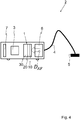
- FIG. 4 illustrates an exemplary vacuum cleaner 2 according to a second aspect of embodiments herein.
- the vacuum cleaner 2 comprises an electric motor and fan unit 3.
- the unit 3 creates a lower pressure inside the vacuum cleaner 2 than the atmospheric pressure on the outside of the vacuum cleaner 2. This difference in pressure causes the air and dust to be sucked into the vacuum cleaner 2 via a hose 4 and a nozzle 5.
- the dust that is sucked into the vacuum cleaner 2 is mainly collected in a dust compartment 6. However, some dust will stay in the airflow D AF and follow the airflow through the motor and fan unit 3 before it is exhausted back into the atmosphere.
- the filter 1, as described above may be arranged upstream of the motor and fan unit 3.
- the vacuum cleaner may be opened to allow a removal of the filter 1 from the vacuum cleaner 2.
- the vacuum cleaner 2 may further comprise an exhaust filter 7 for further reducing the amount of dust and/or odours being released back into the atmosphere.
Landscapes
- Engineering & Computer Science (AREA)
- Mechanical Engineering (AREA)
- Filters For Electric Vacuum Cleaners (AREA)
Abstract
Description
- The embodiments herein relate to a filter for a vacuum cleaner.
- In vacuum cleaners a fan driven by an electric motor is used to create a lower pressure inside the vacuum cleaner than the atmospheric pressure on the outside. The difference in pressure causes air and dust to be sucked into the vacuum cleaner. The dust is then collected in a container arranged inside the vacuum cleaner. This container may e.g. be a bag which allows air to pass through but still traps most of the dust or a removable collection bin into which the dust and debris is forced by means of e.g. cyclonic separation. However, not all of the dust is collected by these containers, and some amount of fine dust will pass the container and follow the airflow through the fan and the electric motor until it is exhausted into the ambient air.
- In order to protect the components of the vacuum cleaner, especially the electric motor, from dust which would otherwise damage the components, additional filters are applied to remove a substantial amount of the remaining dust particles. A main filter may be arranged upstream of the electric motor to filter out fine dust particles from the airflow and pass the filtered air through to the motor for cooling purposes. It is however difficult for a practical air filter to completely remove all ultrafine particles from a dust-laden airflow, if the filter is too fine the filter will immediately clog up and limit the airflow passing through the filter which will render the vacuum cleaner ineffective during everyday use. Practical filters are however a compromise between filtering effectiveness and restriction of airflow. In order to ensure a correct function of the vacuum cleaner the main filter is usually removable in order to allow a clogged filter to be cleaned such that it regains its initial performance. The filters often comprise several filtration layers for collecting dust, which are fixedly attached to each other in a cascaded manner. In order to clean the filter, the dust has to be forced through several of the filtration layers in order to remove the dust which is e.g. trapped in an intermediate filter. This task is not very user friendly since the cleaning process is very time consuming and labor intensive. Furthermore, before the filter can be reinserted into the vacuum cleaner the filter needs to dry, hence the filter cannot be cleaned directly prior to the vacuuming. As a result, cleaning of the filters is often neglected by the user which causes the performance of the vacuum cleaner to drastically decrease and may in the long run lead to a failure of the vacuum cleaner.
- Therefore, in view of the above, there is a need for an improved filter which improves the user friendliness of the vacuum cleaner.
- An object of the embodiments herein is to provide an improved filter for a vacuum cleaner which facilitates the cleaning and thus improves the user friendliness of the vacuum cleaner, or to at least provide a useful alternative to known filters.
- According to an aspect of the embodiments herein, the object is achieved by a filter for a vacuum cleaner. The filter comprises a frame and a plurality of filtration layers. The filtration layers are arranged such that a main surface of the filtration layers are facing each other. The filtration layers are attached to the frame along a first section of a peripheral edge of each filtration layer. The filtration layers comprise a second free section of the peripheral edge which is unattached to the frame. Thereby, the plurality of filtration layers are held together at the first section of the peripheral edge and can be separated from each other along the second free section of the peripheral edge.
- According to some embodiments herein, the first section may cover 20-50 %, preferably equal to or less than 25% of a total length of the peripheral edge of the filtration layers.
- According to some embodiments herein, the peripheral edge of each filtration layer has a plurality of distinct sides, such that the filter has a polygonal shape. At least one of the distinct sides comprises the first section.
- This allows the filtration layers to be separated during cleaning, such that any dust caught between the filtration layers can be more easily removed. By separating the filtration layers the main surfaces of each filtration layer can be rinsed off with water. Furthermore by separating the filtration layers during the drying process, the drying time of the filter can be drastically reduced. As a result, the above mentioned object is achieved.
- According to some embodiments herein each of the filtration layers of the filter may have a finer mesh than the preceding filtration layer as seen in an intended direction of an airflow passing through the filter in an active state. Thereby the larger dust particles are caught by the first filtration layer while the finer dust particles can pass through the first filtration layer but are caught by the following filtration layer having a finer mesh. Thus the dust collected by the filter is distributed over a plurality of layers, which increases the time before the filter is clogged up and needs to be cleaned.
- According to some embodiments the filter may comprise three filtration layers. Thereby the collected dust is distributed over the three layers, which further increases the time the filter can be used before a cleaning of the filter is required.
- According to some embodiments the plurality of filtration layers may be attached to the frame by means of an adhesive. Thereby the filter can be assembled in an easy and cost efficient way.
- This ensures that the seating of the filter against a mounting surface in the vacuum cleaner is not obstructed by the frame, thereby preventing air and dust particles to flow around the filter without being filtered by the filtration layers.
- The frame may comprise a resilient material, such as e.g. TPE, TPU or rubber. By making the frame resilient the filter and the frame can be wringed in order to remove any excess water after cleaning, in order to reduce the drying time of the filter.
- In some embodiments the frame and/or the filtration layers may have an asymmetrical shape to ensure a correct mounting of the filter in the vacuum cleaner.
- In some embodiments the frame may comprise a gripping portion. The gripping portion allows for easy removal of the filter for cleaning, without the user having to touch the dust collected in the filter.
- The gripping portion may be arranged off centre in order to provide the asymmetrical shape of the frame.
- According to a second aspect of embodiments herein the object is achieved by a means of a vacuum cleaner comprising a filter according to any of the embodiments described above.
- Further features of, and advantages with, the present invention will become apparent when studying the appended claims and the following detailed description. Those skilled in the art will realize that the different features described may be combined to create embodiments other than those described in the following, without departing from the scope of the present invention, as defined by the appended claims.
- The various aspects of the invention, including its particular features and advantages, will be readily understood from the following detailed description and the accompanying drawings, in which;
- Fig. 1
- illustrates the filter seen from a perspective view;
- Fig. 2
- illustrates the filter seen in the intended direction of an airflow through the filter,
- Fig. 3
- illustrates the filter seen in a direction perpendicular to the intended direction of an airflow through the filter,
and - Fig. 4
- illustrates a vacuum cleaner comprising a filter according to the embodiments disclosed herein.
- The embodiments herein will now be described more fully with reference to the accompanying drawings. Like numbers refer to like elements throughout.
-
Figure 1 illustrates afilter 1 for a vacuum cleaner. Thefilter 1 may e.g. be a main filter in a bagless vacuum cleaner for separating fine dust. The filter comprises aframe 40 and a plurality of filtration layers 10, 20, 30. In the embodiment shown infigure 1 the filter comprises threefiltration layers filtration layer second filtration layer filtration layer main surface 11a, 21a, 31a and one exitingmain surface figure 3 . - The filtration layers 10, 20, 30 are attached, e.g. by means of an adhesive, to the
frame 40 along a first section of a peripheral edge of eachfiltration layer frame 40 and also in relation to each other to form a unit. The peripheral edges are the surfaces connecting the twomain surfaces 10a, 20a, 30a of eachfiltration layer filtration layer frame 40 nor to anyother filtration layers filter 1 may have a book style configuration, in which the filtration layers 10, 20, 30 correspond to the pages of a book and theframe 40 corresponds to the back of the book which holds the pages together. The first section of the filtration layers 10, 20, 30 may cover 20-50 % of a total length of the peripheral edge of the filtration layers 10, 20, 30. In one embodiment the first section of the filtration layers 10, 20, 30 may be equal to or less than 25% of the total length of the peripheral edge of the filtration layers 10, 20, 30. - In the exemplary embodiment shown in
figure 1 , the peripheral edge of eachfiltration layer filter 1 has a polygonal shape. At least one of the distinct sides may comprise the first section attached to theframe 40. The first section may also extend, at least partly, on to one or more second distinct sides of the filtration layers 10, 20, 30. However, thefilter 1 and the filtration layers 10, 20, 30 may in some embodiments also have a circular or oval shape having only one peripheral edge. - The plurality of filtration layers 10, 20, 30 may all have different thicknesses and densities, which may also be referred to as having different meshes. By varying the thickness and the density of the filtration layers 10, 20, 30, each layer of the
filter 1 may be adapted for a specific purpose, such as e.g. collecting dust particles of a specific size. Providing varying mesh densities of the filtration layers 10, 20, 30 also reduces the pressure fall over thefilter 1. Each of the filtration layers 10, 20, 30 may have a finer mesh than the precedingfiltration layer filter 1 in an active state. Preferably, thefirst filtration layer 10 when seen in the direction DAF may have the smallest density, i.e. providing larger openings in the mesh. This may also be referred to as having the least dense mesh of the filtration layers 10, 20, 30. Thisfirst filtration layer 10 collects the largest dust particles contained in the airflow reaching thefilter 1. Having the least dense mesh also allows thefirst filtration layer 10 to hold more dust before it clogs up. The smaller particles pass through thefirst filtration layer 10 and reach thesecond filtration layer 20 which has a higher density than thefirst filtration layer 10, which may also be referred to as having a finer mesh than thefirst filtration layer 10. Thesecond filtration layer 20 collects a large amount of the dust particles that have passed through thefirst filtration layer 10. However, a certain amount of dust particles will also pass through thesecond layer 20 and reach thethird filtration layer 30 which has the highest density of the filtration layers 10, 20, 30. Hence, the dust entering thefilter 1 will be collected in the filtration layers 10, 20, 30 and on the entering main surface 11a of thefirst layer 10, on the enteringmain surface 21a of thesecond filtration layer 20, as well as on the entering main surface 31a of thethird filtration layer 30. In order to increase the efficiency of thefilter 1 in the limited space provided in a vacuum cleaner, thethird filtration layer 30 in the embodiments shown herein has the largest thickness of the filtration layers 10, 20, 30, since increasing the thickness of the finest filtration layer is the most efficient way to increase the filtration rate of the filter. Hence, this configuration provides a very efficient filter in relation to the required space. If space permits it would however be beneficial to also increase the thickness of the first andsecond filtration layer - In order to facilitate the removal of the dust collected in the filtration layers 10, 20, 30 and on the entering
main surfaces 21a and 31a, which will be trapped between the filtration layers 10, 20, 30, the filtration layers can be separated in order to provide a better access to the dust collected in and on the filtration layers 10, 20, 30. The filtration layers 10, 20, 30 comprise a material which is suitable for allowing air to pass through thefiltration layer - In the embodiment shown in
figure 1 , theframe 40 solely abuts the peripheral edge of the filtration layers 10, 20, 30. Solely abutting the peripheral edge of the filtration layers 10, 20, 30 shall herein be interpreted as not extending over any of the main surfaces of the filtration layers 10, 20, 30. This ensures that the seating of the main surface of thefiltration layer frame 40, which minimizes the risk of leakage around the filter. - The
frame 40 may further comprise a resilient material, such as e.g. TPE, TPU or rubber. The resilient material of theframe 40 allows the filtration layers 10, 20, 30 and the frame to be wringed in order to remove any excess water after cleaning, in order to reduce the drying time of the filter. In case the frame would be rigid, a wringing of the filtration layers 10, 20, 30 would subject the attachment between the filtration layers 10, 20, 30 and therigid frame 40 to high loads, which potentially could cause the filtration layers 10, 20, 30 to be torn off theframe 40. - The
frame 40 may further comprise a grippingportion 41, which allows the user to grab thefilter 1 without having to touch the dust covered filter, e.g. in order to remove thefilter 1 for cleaning. The grippingportion 41 may e.g. be shaped as a tab extending perpendicular to the frame. In some embodiments the grippingportion 41 may comprise a cut out 42 which makes it easier for the user to remove thefilter 1, e.g. by inserting a finger into the cut out 42 and pulling the grippingportion 41 towards the user. The cut out 42 further works as a hanger, which allows thefilter 1 to be hung on e.g. a hook, a screw or a nail during a drying process. - As can be seen in
figure 1 , theframe 40 and/or the filtration layers 10, 20, 30 may have an asymmetrical shape to ensure a correct mounting of thefilter 1 in the vacuum cleaner. The grippingportion 41 of theframe 40 may e.g. be arranged off centre on theframe 40, as seen both in the direction DAF of the airflow, as shown infigure 2 , and as seen in a direction perpendicular to the direction DAF, as shown infigure 3 . The asymmetrical shape may further be achieved by the filtration layers 10, 20, 30 may comprising a cropped corner, as can be seen infigure 1 . Thefilter 1 may comprise either one of or both of the above mentioned features providing the asymmetry. The cropped corner of the filtration layers 10, 20, 30, and/or the grippingportion 41 arranged off centre act as keys interacting with a corresponding shape on the filter housing in the vacuum cleaner, thereby ensuring that the filter can only be mounted in one correct position, e.g. with regards to the direction of the airflow. - In one embodiment, which is not shown in the figures, the
frame 40 may cover a plurality of peripheral edges of the filtration layers 10, 20, 30. Theframe 40 may for example comprise a second portion extending perpendicular to the portion of theframe 40 shown infigure 1 , such that the second portion abuts and attaches to a second peripheral side edge of each filtration layer. In this embodiment, the free peripheral edges may be arranged opposite the peripheral side edges which are attached to the frame in order to allow the filtration layers to be separated, which may also be referred to as being spread out, from one corner, e.g. the corner diagonally opposite the corner where the two portions of theframe 40 are connected. This may e.g. be achieved by pressing the two portions of theframe 40 towards each other which will cause the filtration layers to separate from each other, which may also be referred to as thefilter 1 unfolding. By using two frame portions the filter may be unfolded for cleaning without the user having to touch the dust collected on the filtration layers 10, 20, 30 - In a further embodiment, which is also not shown in the figures, the
frame 40 may comprise two separate portions attached to two opposite peripheral side edges. Thereby the filtration layers 10, 20, 30 may be separated or spread apart by pushing the two portions of theframe 40 towards each other. This will cause the filtration layers, which are only connected via theframe 40, to separate from each other thereby allowing the dust to be rinsed off the main surfaces of the filtration layers 10, 20, 30 without the user having to touch the dust collected on the filtration layers 10, 20, 30. In this embodiment, the peripheral edge of the filtration layers 10, 20, 30 may comprise two first sections attached to a respective portion of theframe 40. -
Figure 2 illustrates thefilter 1 seen in the intended direction of the airflow DAF through thefilter 1. As can be seen, in this embodiment theframe 40 may be substantially arranged to abut the peripheral edge of the filtration layers 10, 20, 30 without covering any part of the main surfaces of the filtration layers 10, 20, 30. This ensures that the seating of thefilter 1 against a mounting surface in the vacuum cleaner is not obstructed by theframe 40, thereby preventing air and dust particles to flow around the filter without being filtered by the filtration layers 10, 20, 30. - However, in some embodiments the
frame 40 may also have a U-shaped cross section which may cover a minor part of the main surfaces. As is further evident from the embodiment shown infigure 2 , the filtration layers 10, 20, 30 may comprise a cropped corner and theframe 40 may comprise the grippingportion 41 being arranged off centre, providing thefilter 1 with an asymmetrical shape for ensuring correct mounting of thefilter 1 in the filter housing of the vacuum cleaner. -
Figure 3 illustrates thefilter 1 withseparated filtration layers filter 1. As can be seen fromfigure 3 , the filtration layers 10, 20, 30 are secured in relation to each other by the attachment to theframe 40. In the embodiment shown in the figures, theframe 40 is only attached to one peripheral edge of eachfiltration layer figure 3 , the grippingportion 41 may also be asymmetrically arranged on the frame when seen in a direction perpendicular to the intended direction DAF of the airflow. By separating the filtration layers from each other, drying of the filter may further be improved. This is due to the fact that the filtration layers 10, 20, 30 are ventilated in a more efficient way when they are separated, than when they abut each other. The way the layers are arranged makes the deep cleaning and drying process of the filter much easier and faster since the dust is more accessible with the layers spread out. -
Figure 4 illustrates anexemplary vacuum cleaner 2 according to a second aspect of embodiments herein. Thevacuum cleaner 2 comprises an electric motor andfan unit 3. Theunit 3 creates a lower pressure inside thevacuum cleaner 2 than the atmospheric pressure on the outside of thevacuum cleaner 2. This difference in pressure causes the air and dust to be sucked into thevacuum cleaner 2 via ahose 4 and anozzle 5. The dust that is sucked into thevacuum cleaner 2 is mainly collected in adust compartment 6. However, some dust will stay in the airflow DAF and follow the airflow through the motor andfan unit 3 before it is exhausted back into the atmosphere. In order to prevent dust from collecting on the motor andfan unit 3, thefilter 1, as described above, may be arranged upstream of the motor andfan unit 3. Thereby the dust is collected by the filtration layers 10, 20, 30 of thefilter 1 before it reaches the electric motor andfan unit 3. In order to remove the collected dust from thefilter 1, the vacuum cleaner may be opened to allow a removal of thefilter 1 from thevacuum cleaner 2. Thevacuum cleaner 2 may further comprise anexhaust filter 7 for further reducing the amount of dust and/or odours being released back into the atmosphere.
Claims (13)
- Filter (1) for a vacuum cleaner, wherein said filter (1) comprises a frame (40) and a plurality of filtration layers (10, 20, 30) arranged such that a main surface (11, 21, 31; 11a, 11b, 21a, 21b, 31a, 31b) of the filtration layers (10, 20, 30) are facing each other, wherein the filtration layers (10, 20, 30) are attached to the frame (40) along a first section of a peripheral edge of each filtration layer (10, 20, 30), and wherein the filtration layers (10, 20, 30) comprise a second free section of the peripheral edge which is unattached to the frame (40), such that the plurality of filtration layers (10, 20, 30) are held together at the first section of the peripheral edge and can be separated from each other along the second free section of the peripheral edge.
- Filter (1) according to claim 1, wherein the first section covers 20-50 %, preferably equal to or less than 25% of a total length of the peripheral edge of the filtration layers (10, 20, 30).
- Filter (1) according to any of the preceding claims, wherein the peripheral edge of each filtration layer (10, 20, 30) has a plurality of distinct sides, such that the filter (1) has a polygonal shape, and wherein at least one of the distinct sides comprises the first section.
- Filter (1) according to any of the preceding claims, wherein each of the filtration layers (10, 20, 30) has a finer mesh than the preceding filtration layer (10, 20, 30) as seen in an intended direction of an airflow passing through the filter in an active state.
- Filter (1) according to any of the preceding claims, wherein the filter (1) comprises three filtration layers (10, 20, 30).
- Filter (1) according to any of the preceding claims, wherein the plurality of filtration layers (10, 20, 30) are attached to the frame (40) by means of an adhesive.
- Filter (1) according to any of the preceding claims, wherein the frame (40) comprises a resilient material, such as e.g. TPE, TPU or rubber.
- Filter (1) according to any of the preceding claims, wherein the frame (40) and/or the filtration layers (10, 20, 30) have an asymmetrical shape to ensure a correct mounting of the filter (1) in the vacuum cleaner.
- Filter (1) according to any of the preceding claims, wherein the frame (40) comprises a gripping portion (41).
- Filter (1) according to claims 8 and 9, wherein the gripping portion (41) is arranged off centre in order to provide the asymmetrical shape of the frame (40).
- Filter (1) according to any of the claims 9 or 10, wherein the gripping portion 41 comprise a cut out 42 for hanging the filter 1 on e.g. a hook, a screw or a nail during a drying process
- Filter (1) according to any of the preceding claims, wherein the filtering layers (10, 20, 30) are foam layers.
- A vacuum cleaner comprising a filter (1) according to any of the preceding claims 1-12.
Priority Applications (2)
| Application Number | Priority Date | Filing Date | Title |
|---|---|---|---|
| EP17207221.7A EP3498140B1 (en) | 2017-12-14 | 2017-12-14 | Filter for a vacuum cleaner |
| CN201811517654.6A CN109953691B (en) | 2017-12-14 | 2018-12-12 | Filter for vacuum cleaner |
Applications Claiming Priority (1)
| Application Number | Priority Date | Filing Date | Title |
|---|---|---|---|
| EP17207221.7A EP3498140B1 (en) | 2017-12-14 | 2017-12-14 | Filter for a vacuum cleaner |
Publications (2)
| Publication Number | Publication Date |
|---|---|
| EP3498140A1 true EP3498140A1 (en) | 2019-06-19 |
| EP3498140B1 EP3498140B1 (en) | 2020-07-15 |
Family
ID=60673543
Family Applications (1)
| Application Number | Title | Priority Date | Filing Date |
|---|---|---|---|
| EP17207221.7A Active EP3498140B1 (en) | 2017-12-14 | 2017-12-14 | Filter for a vacuum cleaner |
Country Status (2)
| Country | Link |
|---|---|
| EP (1) | EP3498140B1 (en) |
| CN (1) | CN109953691B (en) |
Cited By (1)
| Publication number | Priority date | Publication date | Assignee | Title |
|---|---|---|---|---|
| USD1085601S1 (en) * | 2023-09-29 | 2025-07-22 | Yu Xu | Dust collecting box |
Citations (5)
| Publication number | Priority date | Publication date | Assignee | Title |
|---|---|---|---|---|
| JPS4117814Y1 (en) * | 1964-07-15 | 1966-08-18 | ||
| JPS50106062U (en) * | 1974-02-04 | 1975-09-01 | ||
| JPS52113568A (en) * | 1976-03-22 | 1977-09-22 | Toshiba Corp | Dust collector for vacuum cleaner |
| DE3918237A1 (en) * | 1989-06-05 | 1990-12-06 | Miele & Cie | Electric vacuum cleaner with fine dust filter - uses several filter stages in series each utilising replaceable filter element |
| GB2400020A (en) * | 2003-04-04 | 2004-10-06 | Samsung Kwangju Electronics Co | Filter assembly mounting of a bagless vacuum cleaner |
Family Cites Families (15)
| Publication number | Priority date | Publication date | Assignee | Title |
|---|---|---|---|---|
| GB2095327B (en) * | 1981-03-24 | 1984-09-19 | Univ Manchester | Fly wheel arrangement in an internal combustion engine |
| DE3940264A1 (en) * | 1989-12-06 | 1991-06-13 | Hoechst Ag | TWO OR MULTILAYER LIQUID MATERIAL, ESPECIALLY WITH LONG-TERM FILTER PROPERTIES, AND METHOD FOR THE PRODUCTION THEREOF |
| CN1683054B (en) * | 2004-03-30 | 2010-12-29 | 松下电器产业株式会社 | Filter and electric vacuum cleaner using the filter |
| US20100126128A1 (en) * | 2008-11-25 | 2010-05-27 | Scott Iii Richard J | Rigid cell filter assembly |
| WO2011011620A1 (en) * | 2009-07-22 | 2011-01-27 | Donaldson Company, Inc. | Filter media construction using ptfe film and carbon web for hepa efficiency and odor control |
| US8764870B2 (en) * | 2010-09-16 | 2014-07-01 | Cummins Filtration Ip, Inc. | V-shaped filter and fixture |
| CN102225281A (en) * | 2011-03-31 | 2011-10-26 | 厦门建霖工业有限公司 | Multifunctional three-layer type air strainer |
| JP2013022547A (en) * | 2011-07-25 | 2013-02-04 | Nitto Denko Corp | Filter unit and cleaner provided with the same |
| EP2843122B1 (en) * | 2013-08-28 | 2017-02-08 | Electrolux Appliances Aktiebolag | A drying air filter for a laundry dryer and a laundry dryer |
| ES2625427T3 (en) * | 2014-04-08 | 2017-07-19 | Eurofilters N.V. | Filter bag for dust vacuum cleaners for a vertical dust vacuum cleaner |
| CN205627396U (en) * | 2016-03-29 | 2016-10-12 | 慈溪市桥头思域工业产品设计室 | Multistage dust filter of filter screen detachable |
| CN206285619U (en) * | 2016-04-16 | 2017-06-30 | 石阳 | Purified filter material and the filter core for possessing air-cleaning function including the purified filter material |
| CN206613275U (en) * | 2016-12-23 | 2017-11-07 | 深圳市金麒麟环境科技有限公司 | A kind of sub- effective filter |
| CN107192113A (en) * | 2017-04-27 | 2017-09-22 | 舒尔环保科技(合肥)有限公司 | A kind of airstrainer and its filter screen bracket |
| CN208018310U (en) * | 2018-01-08 | 2018-10-30 | 小狗电器互联网科技(北京)股份有限公司 | Filter device and dust catcher |
-
2017
- 2017-12-14 EP EP17207221.7A patent/EP3498140B1/en active Active
-
2018
- 2018-12-12 CN CN201811517654.6A patent/CN109953691B/en active Active
Patent Citations (5)
| Publication number | Priority date | Publication date | Assignee | Title |
|---|---|---|---|---|
| JPS4117814Y1 (en) * | 1964-07-15 | 1966-08-18 | ||
| JPS50106062U (en) * | 1974-02-04 | 1975-09-01 | ||
| JPS52113568A (en) * | 1976-03-22 | 1977-09-22 | Toshiba Corp | Dust collector for vacuum cleaner |
| DE3918237A1 (en) * | 1989-06-05 | 1990-12-06 | Miele & Cie | Electric vacuum cleaner with fine dust filter - uses several filter stages in series each utilising replaceable filter element |
| GB2400020A (en) * | 2003-04-04 | 2004-10-06 | Samsung Kwangju Electronics Co | Filter assembly mounting of a bagless vacuum cleaner |
Cited By (1)
| Publication number | Priority date | Publication date | Assignee | Title |
|---|---|---|---|---|
| USD1085601S1 (en) * | 2023-09-29 | 2025-07-22 | Yu Xu | Dust collecting box |
Also Published As
| Publication number | Publication date |
|---|---|
| CN109953691B (en) | 2022-11-22 |
| EP3498140B1 (en) | 2020-07-15 |
| CN109953691A (en) | 2019-07-02 |
Similar Documents
| Publication | Publication Date | Title |
|---|---|---|
| JP5007713B2 (en) | Cleaning appliance | |
| CA1037390A (en) | Electric cleaner | |
| JP3168865U (en) | Dust collection container and vacuum cleaner having dust collection container | |
| JP3922574B2 (en) | Dust collection container for vacuum cleaner | |
| RU2262287C1 (en) | Filtering unit for vacuum cleaner (versions) and dust catcher with filtering unit | |
| RU2291660C1 (en) | Cyclone-type dust catching apparatus | |
| RU2005133922A (en) | Cyclone Dust Separator And Vacuum Cleaner Containing A Cyclone Dust Separator | |
| JP2012176244A (en) | Filter assembly | |
| US20210186286A1 (en) | Vacuum cleaner | |
| CN101091635A (en) | Electric dust collector | |
| EP3498140B1 (en) | Filter for a vacuum cleaner | |
| JP2003339593A (en) | Vacuum cleaner | |
| KR100572877B1 (en) | Dust filter cleaning structure of vacuum cleaner | |
| US7291189B2 (en) | Dust collecting apparatus for vacuum cleaner | |
| JP5290492B2 (en) | Oil mist removal device | |
| JPS6122563B2 (en) | ||
| JP2005237860A (en) | Vacuum cleaner | |
| KR100751764B1 (en) | Exhaust filter for vacuum cleaner | |
| JP4894381B2 (en) | Vacuum cleaner | |
| JP3114916U (en) | Oil mist removal device | |
| US20080236120A1 (en) | Prefilters for Devices with Air Filter | |
| US20070056135A1 (en) | Electric vacuum cleaner | |
| EP1674015B1 (en) | Electric cleaner | |
| JP5724901B2 (en) | Air purifier unit | |
| RU2335228C1 (en) | Vacuum cleaner |
Legal Events
| Date | Code | Title | Description |
|---|---|---|---|
| PUAI | Public reference made under article 153(3) epc to a published international application that has entered the european phase |
Free format text: ORIGINAL CODE: 0009012 |
|
| STAA | Information on the status of an ep patent application or granted ep patent |
Free format text: STATUS: THE APPLICATION HAS BEEN PUBLISHED |
|
| AK | Designated contracting states |
Kind code of ref document: A1 Designated state(s): AL AT BE BG CH CY CZ DE DK EE ES FI FR GB GR HR HU IE IS IT LI LT LU LV MC MK MT NL NO PL PT RO RS SE SI SK SM TR |
|
| AX | Request for extension of the european patent |
Extension state: BA ME |
|
| STAA | Information on the status of an ep patent application or granted ep patent |
Free format text: STATUS: REQUEST FOR EXAMINATION WAS MADE |
|
| 17P | Request for examination filed |
Effective date: 20191219 |
|
| RBV | Designated contracting states (corrected) |
Designated state(s): AL AT BE BG CH CY CZ DE DK EE ES FI FR GB GR HR HU IE IS IT LI LT LU LV MC MK MT NL NO PL PT RO RS SE SI SK SM TR |
|
| GRAP | Despatch of communication of intention to grant a patent |
Free format text: ORIGINAL CODE: EPIDOSNIGR1 |
|
| STAA | Information on the status of an ep patent application or granted ep patent |
Free format text: STATUS: GRANT OF PATENT IS INTENDED |
|
| INTG | Intention to grant announced |
Effective date: 20200206 |
|
| GRAS | Grant fee paid |
Free format text: ORIGINAL CODE: EPIDOSNIGR3 |
|
| GRAA | (expected) grant |
Free format text: ORIGINAL CODE: 0009210 |
|
| STAA | Information on the status of an ep patent application or granted ep patent |
Free format text: STATUS: THE PATENT HAS BEEN GRANTED |
|
| AK | Designated contracting states |
Kind code of ref document: B1 Designated state(s): AL AT BE BG CH CY CZ DE DK EE ES FI FR GB GR HR HU IE IS IT LI LT LU LV MC MK MT NL NO PL PT RO RS SE SI SK SM TR |
|
| REG | Reference to a national code |
Ref country code: GB Ref legal event code: FG4D Ref country code: CH Ref legal event code: EP |
|
| REG | Reference to a national code |
Ref country code: IE Ref legal event code: FG4D |
|
| REG | Reference to a national code |
Ref country code: DE Ref legal event code: R096 Ref document number: 602017019740 Country of ref document: DE |
|
| REG | Reference to a national code |
Ref country code: AT Ref legal event code: REF Ref document number: 1290025 Country of ref document: AT Kind code of ref document: T Effective date: 20200815 |
|
| REG | Reference to a national code |
Ref country code: LT Ref legal event code: MG4D |
|
| REG | Reference to a national code |
Ref country code: AT Ref legal event code: MK05 Ref document number: 1290025 Country of ref document: AT Kind code of ref document: T Effective date: 20200715 |
|
| REG | Reference to a national code |
Ref country code: NL Ref legal event code: MP Effective date: 20200715 |
|
| PG25 | Lapsed in a contracting state [announced via postgrant information from national office to epo] |
Ref country code: AT Free format text: LAPSE BECAUSE OF FAILURE TO SUBMIT A TRANSLATION OF THE DESCRIPTION OR TO PAY THE FEE WITHIN THE PRESCRIBED TIME-LIMIT Effective date: 20200715 Ref country code: NO Free format text: LAPSE BECAUSE OF FAILURE TO SUBMIT A TRANSLATION OF THE DESCRIPTION OR TO PAY THE FEE WITHIN THE PRESCRIBED TIME-LIMIT Effective date: 20201015 Ref country code: FI Free format text: LAPSE BECAUSE OF FAILURE TO SUBMIT A TRANSLATION OF THE DESCRIPTION OR TO PAY THE FEE WITHIN THE PRESCRIBED TIME-LIMIT Effective date: 20200715 Ref country code: HR Free format text: LAPSE BECAUSE OF FAILURE TO SUBMIT A TRANSLATION OF THE DESCRIPTION OR TO PAY THE FEE WITHIN THE PRESCRIBED TIME-LIMIT Effective date: 20200715 Ref country code: ES Free format text: LAPSE BECAUSE OF FAILURE TO SUBMIT A TRANSLATION OF THE DESCRIPTION OR TO PAY THE FEE WITHIN THE PRESCRIBED TIME-LIMIT Effective date: 20200715 Ref country code: PT Free format text: LAPSE BECAUSE OF FAILURE TO SUBMIT A TRANSLATION OF THE DESCRIPTION OR TO PAY THE FEE WITHIN THE PRESCRIBED TIME-LIMIT Effective date: 20201116 Ref country code: GR Free format text: LAPSE BECAUSE OF FAILURE TO SUBMIT A TRANSLATION OF THE DESCRIPTION OR TO PAY THE FEE WITHIN THE PRESCRIBED TIME-LIMIT Effective date: 20201016 Ref country code: LT Free format text: LAPSE BECAUSE OF FAILURE TO SUBMIT A TRANSLATION OF THE DESCRIPTION OR TO PAY THE FEE WITHIN THE PRESCRIBED TIME-LIMIT Effective date: 20200715 Ref country code: BG Free format text: LAPSE BECAUSE OF FAILURE TO SUBMIT A TRANSLATION OF THE DESCRIPTION OR TO PAY THE FEE WITHIN THE PRESCRIBED TIME-LIMIT Effective date: 20201015 Ref country code: SE Free format text: LAPSE BECAUSE OF FAILURE TO SUBMIT A TRANSLATION OF THE DESCRIPTION OR TO PAY THE FEE WITHIN THE PRESCRIBED TIME-LIMIT Effective date: 20200715 |
|
| PG25 | Lapsed in a contracting state [announced via postgrant information from national office to epo] |
Ref country code: IS Free format text: LAPSE BECAUSE OF FAILURE TO SUBMIT A TRANSLATION OF THE DESCRIPTION OR TO PAY THE FEE WITHIN THE PRESCRIBED TIME-LIMIT Effective date: 20201115 Ref country code: LV Free format text: LAPSE BECAUSE OF FAILURE TO SUBMIT A TRANSLATION OF THE DESCRIPTION OR TO PAY THE FEE WITHIN THE PRESCRIBED TIME-LIMIT Effective date: 20200715 Ref country code: PL Free format text: LAPSE BECAUSE OF FAILURE TO SUBMIT A TRANSLATION OF THE DESCRIPTION OR TO PAY THE FEE WITHIN THE PRESCRIBED TIME-LIMIT Effective date: 20200715 Ref country code: RS Free format text: LAPSE BECAUSE OF FAILURE TO SUBMIT A TRANSLATION OF THE DESCRIPTION OR TO PAY THE FEE WITHIN THE PRESCRIBED TIME-LIMIT Effective date: 20200715 |
|
| PG25 | Lapsed in a contracting state [announced via postgrant information from national office to epo] |
Ref country code: NL Free format text: LAPSE BECAUSE OF FAILURE TO SUBMIT A TRANSLATION OF THE DESCRIPTION OR TO PAY THE FEE WITHIN THE PRESCRIBED TIME-LIMIT Effective date: 20200715 |
|
| REG | Reference to a national code |
Ref country code: DE Ref legal event code: R097 Ref document number: 602017019740 Country of ref document: DE |
|
| PG25 | Lapsed in a contracting state [announced via postgrant information from national office to epo] |
Ref country code: DK Free format text: LAPSE BECAUSE OF FAILURE TO SUBMIT A TRANSLATION OF THE DESCRIPTION OR TO PAY THE FEE WITHIN THE PRESCRIBED TIME-LIMIT Effective date: 20200715 Ref country code: CZ Free format text: LAPSE BECAUSE OF FAILURE TO SUBMIT A TRANSLATION OF THE DESCRIPTION OR TO PAY THE FEE WITHIN THE PRESCRIBED TIME-LIMIT Effective date: 20200715 Ref country code: RO Free format text: LAPSE BECAUSE OF FAILURE TO SUBMIT A TRANSLATION OF THE DESCRIPTION OR TO PAY THE FEE WITHIN THE PRESCRIBED TIME-LIMIT Effective date: 20200715 Ref country code: SM Free format text: LAPSE BECAUSE OF FAILURE TO SUBMIT A TRANSLATION OF THE DESCRIPTION OR TO PAY THE FEE WITHIN THE PRESCRIBED TIME-LIMIT Effective date: 20200715 Ref country code: EE Free format text: LAPSE BECAUSE OF FAILURE TO SUBMIT A TRANSLATION OF THE DESCRIPTION OR TO PAY THE FEE WITHIN THE PRESCRIBED TIME-LIMIT Effective date: 20200715 Ref country code: IT Free format text: LAPSE BECAUSE OF FAILURE TO SUBMIT A TRANSLATION OF THE DESCRIPTION OR TO PAY THE FEE WITHIN THE PRESCRIBED TIME-LIMIT Effective date: 20200715 |
|
| PLBE | No opposition filed within time limit |
Free format text: ORIGINAL CODE: 0009261 |
|
| STAA | Information on the status of an ep patent application or granted ep patent |
Free format text: STATUS: NO OPPOSITION FILED WITHIN TIME LIMIT |
|
| PG25 | Lapsed in a contracting state [announced via postgrant information from national office to epo] |
Ref country code: AL Free format text: LAPSE BECAUSE OF FAILURE TO SUBMIT A TRANSLATION OF THE DESCRIPTION OR TO PAY THE FEE WITHIN THE PRESCRIBED TIME-LIMIT Effective date: 20200715 |
|
| 26N | No opposition filed |
Effective date: 20210416 |
|
| PG25 | Lapsed in a contracting state [announced via postgrant information from national office to epo] |
Ref country code: SK Free format text: LAPSE BECAUSE OF FAILURE TO SUBMIT A TRANSLATION OF THE DESCRIPTION OR TO PAY THE FEE WITHIN THE PRESCRIBED TIME-LIMIT Effective date: 20200715 |
|
| REG | Reference to a national code |
Ref country code: CH Ref legal event code: PL |
|
| PG25 | Lapsed in a contracting state [announced via postgrant information from national office to epo] |
Ref country code: MC Free format text: LAPSE BECAUSE OF FAILURE TO SUBMIT A TRANSLATION OF THE DESCRIPTION OR TO PAY THE FEE WITHIN THE PRESCRIBED TIME-LIMIT Effective date: 20200715 Ref country code: SI Free format text: LAPSE BECAUSE OF FAILURE TO SUBMIT A TRANSLATION OF THE DESCRIPTION OR TO PAY THE FEE WITHIN THE PRESCRIBED TIME-LIMIT Effective date: 20200715 |
|
| REG | Reference to a national code |
Ref country code: BE Ref legal event code: MM Effective date: 20201231 |
|
| PG25 | Lapsed in a contracting state [announced via postgrant information from national office to epo] |
Ref country code: IE Free format text: LAPSE BECAUSE OF NON-PAYMENT OF DUE FEES Effective date: 20201214 Ref country code: LU Free format text: LAPSE BECAUSE OF NON-PAYMENT OF DUE FEES Effective date: 20201214 |
|
| PG25 | Lapsed in a contracting state [announced via postgrant information from national office to epo] |
Ref country code: LI Free format text: LAPSE BECAUSE OF NON-PAYMENT OF DUE FEES Effective date: 20201231 Ref country code: CH Free format text: LAPSE BECAUSE OF NON-PAYMENT OF DUE FEES Effective date: 20201231 |
|
| PG25 | Lapsed in a contracting state [announced via postgrant information from national office to epo] |
Ref country code: TR Free format text: LAPSE BECAUSE OF FAILURE TO SUBMIT A TRANSLATION OF THE DESCRIPTION OR TO PAY THE FEE WITHIN THE PRESCRIBED TIME-LIMIT Effective date: 20200715 Ref country code: MT Free format text: LAPSE BECAUSE OF FAILURE TO SUBMIT A TRANSLATION OF THE DESCRIPTION OR TO PAY THE FEE WITHIN THE PRESCRIBED TIME-LIMIT Effective date: 20200715 Ref country code: CY Free format text: LAPSE BECAUSE OF FAILURE TO SUBMIT A TRANSLATION OF THE DESCRIPTION OR TO PAY THE FEE WITHIN THE PRESCRIBED TIME-LIMIT Effective date: 20200715 |
|
| PG25 | Lapsed in a contracting state [announced via postgrant information from national office to epo] |
Ref country code: MK Free format text: LAPSE BECAUSE OF FAILURE TO SUBMIT A TRANSLATION OF THE DESCRIPTION OR TO PAY THE FEE WITHIN THE PRESCRIBED TIME-LIMIT Effective date: 20200715 |
|
| PG25 | Lapsed in a contracting state [announced via postgrant information from national office to epo] |
Ref country code: BE Free format text: LAPSE BECAUSE OF NON-PAYMENT OF DUE FEES Effective date: 20201231 |
|
| P01 | Opt-out of the competence of the unified patent court (upc) registered |
Effective date: 20230521 |
|
| PGFP | Annual fee paid to national office [announced via postgrant information from national office to epo] |
Ref country code: GB Payment date: 20251223 Year of fee payment: 9 |
|
| PGFP | Annual fee paid to national office [announced via postgrant information from national office to epo] |
Ref country code: FR Payment date: 20251223 Year of fee payment: 9 |
|
| PGFP | Annual fee paid to national office [announced via postgrant information from national office to epo] |
Ref country code: DE Payment date: 20251229 Year of fee payment: 9 |