EP3497404B1 - Method and apparatus for indoor mapping, positioning, or navigation - Google Patents
Method and apparatus for indoor mapping, positioning, or navigation Download PDFInfo
- Publication number
- EP3497404B1 EP3497404B1 EP16754339.6A EP16754339A EP3497404B1 EP 3497404 B1 EP3497404 B1 EP 3497404B1 EP 16754339 A EP16754339 A EP 16754339A EP 3497404 B1 EP3497404 B1 EP 3497404B1
- Authority
- EP
- European Patent Office
- Prior art keywords
- indoor
- block
- features
- indoor block
- feature
- Prior art date
- Legal status (The legal status is an assumption and is not a legal conclusion. Google has not performed a legal analysis and makes no representation as to the accuracy of the status listed.)
- Active
Links
Images





Classifications
-
- G—PHYSICS
- G01—MEASURING; TESTING
- G01C—MEASURING DISTANCES, LEVELS OR BEARINGS; SURVEYING; NAVIGATION; GYROSCOPIC INSTRUMENTS; PHOTOGRAMMETRY OR VIDEOGRAMMETRY
- G01C21/00—Navigation; Navigational instruments not provided for in groups G01C1/00 - G01C19/00
- G01C21/20—Instruments for performing navigational calculations
- G01C21/206—Instruments for performing navigational calculations specially adapted for indoor navigation
-
- G—PHYSICS
- G01—MEASURING; TESTING
- G01C—MEASURING DISTANCES, LEVELS OR BEARINGS; SURVEYING; NAVIGATION; GYROSCOPIC INSTRUMENTS; PHOTOGRAMMETRY OR VIDEOGRAMMETRY
- G01C21/00—Navigation; Navigational instruments not provided for in groups G01C1/00 - G01C19/00
- G01C21/10—Navigation; Navigational instruments not provided for in groups G01C1/00 - G01C19/00 by using measurements of speed or acceleration
-
- G—PHYSICS
- G06—COMPUTING OR CALCULATING; COUNTING
- G06Q—INFORMATION AND COMMUNICATION TECHNOLOGY [ICT] SPECIALLY ADAPTED FOR ADMINISTRATIVE, COMMERCIAL, FINANCIAL, MANAGERIAL OR SUPERVISORY PURPOSES; SYSTEMS OR METHODS SPECIALLY ADAPTED FOR ADMINISTRATIVE, COMMERCIAL, FINANCIAL, MANAGERIAL OR SUPERVISORY PURPOSES, NOT OTHERWISE PROVIDED FOR
- G06Q30/00—Commerce
- G06Q30/02—Marketing; Price estimation or determination; Fundraising
- G06Q30/0241—Advertisements
- G06Q30/0251—Targeted advertisements
- G06Q30/0261—Targeted advertisements based on user location
Definitions
- the present application relates generally to positioning or navigation, and particularly to positioning or navigation in an indoor space.
- a civic address is the official number and name (e.g., street name) that is assigned to a property, building, or structure for identification and/or emergency dispatch purposes. It is a unique identifier for location purposes.
- a civic address may be formed, for example, as "123 Main Street”. Positioning or navigation in an outdoor environment often revolves around civic addresses, especially since outdoor objects are usually large enough to be distinguished from each other.
- Positioning or navigation in an indoor environment proves challenging in part because civic addresses are not as readily usable indoors.
- the division of indoor spaces into a massive number of places such as rooms, hallways, exits, stairs, and the like makes it difficult to simply allocate civic addresses (e.g., room numbers).
- civic addresses e.g., room numbers
- some indoor places constitute open spaces (e.g., reception areas, coffee bars, kitchens), making the allocation of civic addresses to those open spaces challenging. Inherent shortcomings of civic addresses therefore complicate indoor positioning and navigation.
- WO2014194300 (A1 ) a method of providing location services at a location server for a venue.
- An identification of a geographic area comprises a venue-specific identification, like "County A, state B, city C, shopping mall D, store X, cosmetics section”.
- WO2013192022 (A1 ) discloses that a method may comprise: obtaining a digital map of an indoor region that identifies boundaries between subsections within the indoor region; and approximating locations of walls separating rooms within at least one of the subsections based, at least in part, on locations of feature labels provided in the digital map.
- the feature labels that identify individual stores may comprise a name or number.
- US2011/121963 discloses generating trace data corresponding to one or more mobile devices detected within a premise wherein the trace data specifies the movement of the mobile devices within the premise. Using the trace data, it is possible to identify accessibility, connectivity and their availability of areas of the premise.
- One or more embodiments herein identify an indoor block in an indoor space as being located at an address formed from a set of features which describe characteristics of that indoor block.
- Features in the set may be stable features (e.g., describing an indoor block's visual or functional characteristics), statistical features (e.g., describing an indoor block's statistical user occupancy or statistical operating times), and/or dynamic features (e.g., describing an indoor block's current user occupancy).
- this set of features effectively serves as a so-called "feature address" of the indoor block.
- indoor blocks are identified as being located at their respective feature addresses, rather than any civic addresses thereof. With indoor blocks distinguished by their respective feature addresses, one or more embodiments exploit those feature addresses in performing indoor mapping, positioning, and/or navigation.
- Embodiments herein include a method for indoor mapping, positioning, or navigation.
- the method comprises collecting data that is obtained by one or more input devices with which a wireless device is equipped or that describes a trajectory with which the wireless device moves.
- the method further comprises extracting, from the collected data, a set of features which describes characteristics of a place at which the wireless device is located, at which the wireless device targets as a destination, or at which the wireless device targets to avoid.
- the set of features describe characteristics of an indoor block or a place includes one or more statistical features which statistically describe characteristics of the indoor block or the place, and further includes one or more dynamic features which describe characteristics of the indoor block or place in substantially real-time, and furthermore includes one or more stable features which describe substantially static characteristics of the indoor block or place.
- the method also comprises performing, or assisting another node in performing, mapping, positioning, or navigation in the indoor space based on the extracted set of features.
- one or more of the features in a set of features which describe characteristics of an indoor block or a place are extracted from one or more of: trajectory data describing a trajectory of one or more wireless devices moving through the indoor space; imaging data comprising a video or a sequence of pictures taken by one or more wireless devices moving through the indoor space or by an indoor monitoring system; a floor plan of the indoor space; and textual or voice input from one or more wireless devices.
- Embodiments herein also include a corresponding apparatus, computer program, and carrier.
- Figure 1 illustrates a system 10 for addressing different places in an indoor space 12, e.g., for use by the system 10 in performing mapping, positioning, or navigation.
- the system 10 in this regard addresses the different places using sets of features that describe characteristics of those places. In some embodiments, this equips the system 10 with the ability to efficiently address not only different rooms in the indoor space 12, but also other types of places in the indoor space 12.
- Figure 1 shows that the indoor space 12 includes different hallways, doors, stairs, and open spaces.
- the system 10 may address some or all of these different types of places using sets of features describing characteristics of those places.
- the system 10 includes an addressing node 14 configured to address the different places in the indoor space 12.
- the addressing node 14 first determines multiple so-called indoor blocks (IBs) into which the indoor space 12 is spatially divided.
- Figure 1 for example shows the indoor space as being spatially divided into indoor blocks IB1-IB13.
- Indoor blocks IB1, IB2, IB4, and IB5 correspond to different rooms in the indoor space 12
- indoor blocks IB3, IB6, and IB7 correspond to different hallways in the indoor space 12
- indoor blocks IB8, IB9, and IB 10 correspond to different exterior doors of the indoor space 12.
- indoor block IB11 corresponds to a stairway while indoor blocks IB12 and IB13 correspond to different open spaces (e.g., a table and a coffee bar).
- the addressing node 14 or another node in the system 10 actually divides the indoor space 12 into indoor blocks using approaches described in International Application Number PCT/SE206/05038 .
- the indoor space 12 may be divided into indoor blocks that correspond to different clusters of wireless communication device locations. These device locations may be collected for instance based on movement of arbitrary wireless devices through the indoor space 12 in their normal routine (e.g., as the devices' users walk through stores or offices in the indoor space 12), rather than dedicated personnel moving through the space purely for mapping purposes. Boundaries (e.g., walls) and/or the limiting of certain functionality to a defined space (e.g., a coffee bar) contribute to the clustering of device locations, which are exploited to infer and define different indoor blocks in the indoor space 12.
- Boundaries e.g., walls
- limiting of certain functionality to a defined space e.g., a coffee bar
- the addressing node 14 in Figure 1 addresses those indoor blocks. That is, the addressing node 14 assigns each indoor block an address. As shown, for instance, the addressing node 14 assigns IB1 an address ADDR1, assigns IB2 an address ADDR2, assigns IB12 an address ADDR12, assigns IB13 an address ADDR13, etc. Assigned such an address, an indoor block is identified as being located at that address. The indoor blocks are therefore generally distinguishable by their respective addresses.
- each indoor block is formed from a set of features that describe characteristics of that indoor block.
- each address ADDRx for an indoor block IBx is formed from a feature set FSx.
- Each feature set FSx includes multiple features F1, F2,...Fn. Different features in the set FSx describe different characteristics of the indoor block IBx.
- the address ADDRx for an indoor block IBx is the feature set FSx itself, such that the address ADDRx effectively constitutes the combination of features F1, F2,... Fn that describe that indoor block IBx.
- the address ADDRx for an indoor block IBx is just derived from or otherwise depends on the feature set FSx in such a way that the feature set FSx provides a degree of distinction to the address, i.e., so that the addresses serve to distinguish the indoor blocks.
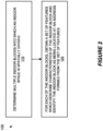
- the addressing node 14 performs a process 100 shown in Figure 2 according to some embodiments.
- the process 100 includes determining multiple indoor blocks into which an indoor space 12 is spatially divided (Block 110).
- the process 100 further includes, for each of the indoor blocks, obtaining a set of features which describe characteristics of the indoor block and identifying the indoor block as being located at an address formed from the set of features (Block 120).
- a feature address therefore differs from a conventional civic address in that a feature address actually describes characteristics of an indoor block, rather than simply being a construct (e.g., a room number) formed only as an otherwise meaningless label to distinguish one place from another without regard to the place's underlying characteristics.
- an indoor block is identified exclusively in the system 10 by its feature address, i.e., the indoor block is not assigned a civic address in the system 10, as a feature address replaces such a civic address. This proves advantageous for instance for addressing types of indoor blocks that do not traditionally have a civic address, such as open areas (e.g., reception areas, coffee areas).
- the feature set from which a feature address is formed may include any type of features which describe characteristics of an indoor block. According to the invention these features are stable features, statistical features, and dynamic features.
- Figure 3A in this regard illustrates one example of a data structure for a feature address which comprises a combination of stable features 20A, statistical features 20B, and dynamic features 20C. Each feature, whether stable, statistical, or dynamic in nature, may describe a characteristic of an indoor block in terms of one or more values.
- Figure 3B for instance shows a feature address formed for an indoor block IB j from M statistical features, J dynamic features, and K stable features.
- F Stas m is the m -th statistical feature with values( U IB j , V IB j , W IB j ),
- F D j is the j-th dynamic feature with values ( X IB j , Y IB j , Z IB j ) and
- F Stab k is the k-th stable feature with values A IB j B IB j C IB j .
- a stable feature describes a substantially static characteristic of an indoor block, i.e., a characteristic that generally remains static over time.
- a name associated with the indoor block e.g., McDonalds, GameStop, etc.
- Another example of a stable feature may describe a functional characteristic of the indoor block.
- a functional characteristic may indicate a type of the indoor block in terms of function (e.g., retail store, office, restaurant, bathroom, staircase, etc.).
- a stable feature may describe a visual characteristic of the indoor block, such as the indoor block's color(s) or shape.
- Another stable feature may describe a physical size of the indoor block, e.g., in terms of the indoor block's specific quantitative dimensions or in terms of qualitative descriptors of those dimensions (e.g., "small” or “big”).
- a stable feature may describe a spatial orientation of the indoor block, which may be specified relative to the indoor space 12 (e.g., "the indoor block is located at the north end of the indoor space”).
- a stable feature may describe a physical location of furniture in the indoor block (e.g., the position of a table).
- a stable feature may describe times at which functionality of the indoor block is available. These times may therefore reflect opening and closing times of the indoor block (e.g., a restaurant or store), as those times are generically defined (e.g., without regard to exceptions such as holidays or special circumstances).
- a statistical feature by contrast statistically describes characteristics of an indoor block, e.g., in terms of average, mean, median, standard deviation, minimum, maximum, percentile, a histogram, or other statistical information.
- this statistical information is generated based on information collected from arbitrary wireless devices as their users move through the indoor space 12 in their normal routine (e.g., as the users walk through stores or offices in the indoor space 12).
- information may include for instance positioning information, trajectory data, imagining data, etc.
- a statistical feature may include for instance statistical information describing times at which wireless devices enter and/or leave the indoor block.
- Such a feature may for example describe at what time devices typically first enter the indoor block over a certain time period, e.g., when users typically first enter the indoor block on any given day so as to reflect for instance when a store typically gets its first customer for the day, or when users typically first enter the indoor block after noon.
- a feature may describe at what time devices typically last leave the indoor block over a certain time period, e.g., when users typically last leave the indoor block on any given day so as to reflect for instance when a store typically has its last customer for the day.
- a statistical feature may include statistical information describing how often wireless devices visit an indoor block.
- the information may for example reflect the frequency at which any devices occupy the indoor block, e.g., so as to characterize how often the indoor block is occupied by devices versus empty without devices.
- a statistical feature may include statistical information describing for how long wireless devices visit an indoor block. The information may for example characterize the typical duration for which any given device occupies the indoor block (e.g., so as to reflect the typical length of a haircut appointment, where the indoor block corresponds to a barber shop or salon).
- a statistical feature may include statistical information describing how many wireless devices visit an indoor block.
- This information may for example characterize the total number of wireless devices that typically occupy the indoor block over the span of a defined time duration (e.g., per day, or per certain hours during the day).
- another statistical feature may include statistical information describing how many wireless devices visit an indoor block simultaneously. That is, the information may characterize the total number of wireless devices that typically occupy the indoor block at the same time, e.g., over the span of a defined time duration. The feature may thereby reflect how crowded an indoor block is typically during certain times (e.g., how crowded the indoor block is during certain hours of a day).
- a statistical feature may include statistical information describing which locations in an indoor block wireless devices visit.
- a statistical feature may include statistical information describing speeds at which wireless devices move through an indoor block.
- a statistical feature may include statistical information describing an electrical, environmental, or physical characteristic of an indoor block, as detected by sensors of wireless devices that visit the indoor block.
- a characteristic may for instance concern electromagnetic radiation, barometric pressure, temperature, humidity, WiFi signal strength, or the like.
- the statistical information for any given statistical feature may describe an indoor block using one or more statistical metrics.
- the statistical information for a given statistical feature describes an indoor block in terms of average, mean, and standard deviation.
- Figure 4 in this regard illustrates an example of a data structure maintained by the addressing node 14 for statistical features which describe an indoor block in this way.
- the data structure stores N statistical features F 1 , F 2 ,...F N for each of K indoor blocks IB 1 ...IB K .
- Each of these statistical features includes statistical information describing an indoor block in terms of 3 statistical metrics; namely, an average U, a mean V, and a standard deviation W.
- a statistical feature F 1 describes a characteristic of an indoor block IB 1 in terms of an average U IB1 , a mean V IB1 , and a standard deviation W IB1 of that characteristic.
- the values of these statistical metrics U IB1 , V IB1 , and W IB1 for indoor block IB 1 are likely to differ from the values of those same metrics U IB2 , V IB2 , V IB2 for indoor block IB 2 due to the indoor blocks differing in terms of the statistical feature F 1 .
- the set of statistical features F 1 , F 2 ,...F N along any given row in Figure 4 in whole or in part serve as a feature address of an indoor block.
- the set of features includes, according to the invention, one or more dynamic features.
- a dynamic feature describes a characteristic of an indoor block in substantially real-time. That is, a dynamic feature describes a characteristic of an indoor block as that characteristic changes over time.
- a dynamic feature may therefore be tagged or otherwise associated with a timestamp indicating a time or time interval during which the dynamic feature is valid as representing a characteristic of an indoor block.
- a dynamic feature may describe how many wireless devices are currently visiting an indoor block. Such a feature may thereby reflect how crowded the indoor block is currently.
- a dynamic feature may describe times at which functionality of the indoor block is available. These times may be determined for instance based on whether any devices are actually visiting the indoor block.
- a dynamic feature may describe which locations in the indoor block wireless devices are visiting. The feature may thereby reflect where in the indoor block any wireless devices are located.
- a dynamic feature may describe a location of a specific device that is currently visiting the indoor block. This specific device may be for instance the device of a user who has a specific job-related role (e.g., a manager of a store, a manager of a building, an assistant, a help desk technician, a receptionist, etc.).
- a dynamic feature may describe speeds at which wireless devices are currently moving through the indoor block.
- a dynamic feature may describe an electrical, environmental, or physical characteristic of an indoor block, as detected by a sensor of a wireless device that is currently visiting the indoor block or place.
- a characteristic may for instance concern electromagnetic radiation, barometric pressure, temperature, humidity, WiFi signal strength, or the like.
- a dynamic feature may characterize an indoor block from the perspective of a business operated at that indoor block.
- a dynamic feature may describe a promotion currently offered by a business located at an indoor block (e.g., a current discount, such as 20% off).
- a dynamic feature may describe a product or service currently offered for sale at an indoor block.
- such a dynamic feature describes a product or service that has been newly offered for sale within a certain time frame (e.g., the past 3 days) so as to just indicate a newly available product or service.
- this sort of promotional information is effectively embedded within a feature address, it advantageously allows selective advertisement of that promotional information to only certain users likely to be interested; namely, those that actively search for a certain feature address, as described more fully below. This promotes more successful advertising as well as conserves transmission resources, as contrasted with approaches that broadcast promotional information to anyone and everyone in range.
- this type of business-related dynamic feature may be populated in the system 10 by an owner or administrator of a business located at an indoor block. Alternatively or additionally, it may be populated in the system 10 by a wireless device user, e.g., via crowdsourcing of the business-related information.
- features herein may be extracted by the addressing node 14 or some other node (not shown) from any number of possible "raw" data sources.
- at least one feature is extracted from textual or voice input from one or more wireless device users.
- a user may for instance provide input indicating the name or visual characteristic of a particular indoor block.
- at least one feature may be extracted from imaging data (e.g., a video or a sequence of pictures) from one or more wireless devices moving through the indoor space 12 or from an indoor monitoring system (e.g., surveillance cameras).
- at least one feature is extracted (e.g., via analysis) from a floor plan of the indoor space 12.
- Such a floor plan may be obtained for instance from municipalities or through a multi-camera imaging tool (e.g., Google's Trekker) used to collect pictures of floor plans.
- a multi-camera imaging tool e.g., Google's Trekker
- at least one feature may be extracted from trajectory data describing a trajectory of one or more wireless devices moving through the indoor space 12.
- This trajectory data may be tracked by indoor positioning methods, such as those obtained using fingerprinting based adaptive enhanced cell-ID (AECID). See, e.g., PCT/SE2005/001485 and PCT/SE2006/050068 .
- AECID adaptive enhanced cell-ID
- feature extraction may also be based on inferences made from other features. For example, a stable feature describing functionality of an indoor block may be inferred from one or more statistical features extracted for that indoor block.
- Figures 5A-5B illustrates different embodiments for extracting features for use by the addressing node 14 in addressing indoor blocks.
- an extracting node 16 collects certain "raw" data 18 from which it extracts features 20.
- This raw data may for example be obtained by one or more input devices with which a wireless device is equipped (e.g., a keyboard, a microphone, an imaging device, etc.).
- the raw data may describe a trajectory with which a wireless device moves in the indoor space 12, e.g., as determined by tracking device position. No matter the particular nature of the raw data 18, the extracting node 16 extracts features 20 from that data 18.
- Extraction may for instance entail processing the raw data 18 to detect or otherwise identify certain predefined features from the raw data 18. Extraction of statistical features, in particular, may involve evaluating raw data 18 from a certain period of time (e.g., the past 3 months). The extracting node 16 may perform this evaluation offline.
- the extracting node 16 may then signal those features 20 to the addressing node 14 for use in addressing indoor blocks.
- the extracting node 16 associates the features 20 with certain indoor blocks whose characteristics are described by those features 20, such that the extracting node 16 signals features 20 to the addressing node 14 along with information identifying the associated indoor blocks.
- the extracting node 16 simply associates the features 20 with certain places in the indoor space 12, and the addressing node 14 or some other node determines which indoor blocks the signaled features 20 are associated with.
- the extracting node 16 and the addressing node 14 are the same node, such that no inter-node signaling is required (i.e., the same node both extracts features and addresses indoor blocks using those features).
- the extracting node 16 in some embodiments is a cloud radio access network (C-RAN) node.
- C-RAN cloud radio access network
- Figure 5B illustrates other embodiments where a wireless device itself serves as an extracting node 16.
- a wireless device not only collects the raw data 18 but also extracts features 20 from that data 18.
- the device then signals the extracted features 20 to the addressing node 14, for use by the addressing node 14 in addressing indoor blocks using those features 20.
- the device signals positioning information for the device along with the extracted features 20, where device positioning may be device initiated or network initiated.
- the addressing node 14 determines from the positioning information which indoor block the extracted features 20 are associated with.
- the device signals information indicating the indoor block with which the extracted features 20 are associated.
- This feature collection and/or reporting may be performed via a control and/or user plane. It may be transparent to radio base stations.
- the reporting may be performed via the LTE Positioning Protocol (LPP) and/or LPP extensions (LPPe).
- LPP LTE Positioning Protocol
- LPPe LPP extensions
- the reporting may be performed via radio network nodes, e.g., base stations or radio controllers.
- feature reporting is performed from a user equipment to a radio network node which may then forward the reporting to a positioning node or store locally in the radio network node.
- the collection and/or reporting may be triggered by an event (e.g., upon event occurrence, the event may be reported or logged for later reporting) and/or a condition (e.g., at a certain time).
- collection and/or reporting may be performed upon a request from a network node, such as a positioning node. In still other embodiments, collection and/or reporting may be performed periodically.
- the extracting node 16 may be a wireless device (e.g., a user equipment), a radio network node (e.g., a base station), or a core network node in a wireless communication system.
- the extracting node 16 may be a positioning node, such as an evolved serving mobile location center (E-SMLC).
- the addressing node 14 may be a radio network node or a core network node in a wireless communication system.
- the addressing node 14 may similarly be a positioning node such as an E-SMLC.
- the extracting node 16 performs, or assists another node in performing, mapping, positioning, or navigation in the indoor space 12 based on the set of features that it extracts.
- Figure 6 illustrates a process 200 performed by the extracting node 16.
- the process 200 includes collecting data that is obtained by one or more input devices with which a wireless device is equipped or that describes a trajectory with which the wireless device moves (Block 210). This data may for instance text or voice input by the wireless device user, imaging data captured by the device, trajectory data collected for the device, etc.
- the process 200 further includes extracting, from the collected data, a set of features which describes characteristics of a place, e.g., associated with the device and/or its user (Block 220).
- This place may be for instance a place at which the wireless device is located, a place at which the wireless device targets as a destination, or a place at which the wireless device targets to avoid.
- the process 200 also includes performing, or assisting another node in performing, mapping, positioning, or navigation in the indoor space 12 based on the extracted set of features (Block 230).
- such assistance may entail signaling the extracted set of features to another node, e.g., the addressing node 14.
- this signaling may accompany positioning information for the wireless device, e.g., so that a database of feature sets associated with certain positions can be built up.
- the addressing node 14 in some embodiments performs, or assists another node in performing, mapping, positioning, or navigation in the indoor space 12 based on its feature-based addressing of the indoor blocks.
- Mapping may involve for instance generating a map with the indoor blocks distinguished by their respective feature addresses.
- the indoor block may be displayed on the map with one or more features from its feature address denoted as a label. This label may appear directly on the map (when this service is turned on) or as background information (when this service is turned off).
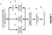
- Figure 7 illustrates one embodiment of a process performed by one or more nodes for generating such a map.
- the process includes obtaining data from one or more data sources 22, such as trajectory data, imaging data, floor plan images, or the like (Block 22).
- the process further includes, based on the obtained data, performing statistical feature extraction (Block 24), performing stable feature extraction (Block 26), and/or conditionally performing dynamic feature extraction (Block 28) at a certain time (Block 30). This extraction may be performed for instance by extraction node 16.
- the process includes forming or otherwise generating complete feature addresses for those indoor blocks, e.g., by combining the features extracted for any given indoor block into a set and assigning that feature set as the indoor block's address (Block 32). Such may be performed by addressing node 14.
- the process further includes labeling the indoor blocks with feature(s) from their respective feature addresses, e.g., so as to actually display some or all of those features on the map. As a result of this process, a map of an indoor space 12 is generated with indoor blocks identified by respective feature addresses (Block 36).
- the map may then be displayed to a wireless device user, e.g., for manual positioning or navigation purpose.
- the map may be analyzed or otherwise used by a positioning or navigation node for such purposes.
- Indoor positioning or navigation in this regard, with or without reference to a machine-generated map, may exploit feature-based addressing herein in order to determine the position of a certain place in the indoor space 12.
- indoor positioning or navigation may entail obtaining a feature set describing characteristics of a certain place in the indoor space 12 and then pinpointing a position of that place by identifying which of the indoor blocks has a feature address that best matches the obtained feature set.
- This approach advantageously enables positioning or navigation on a block-by-block basis, without reliance on conventional indoor positioning methods such as time of arrival (TOA), angle of arrival (AOA), received signal strength indication (RSSI), etc.
- TOA time of arrival
- AOA angle of arrival
- RSSI received signal strength indication
- Figure 8 illustrates one example process 300 for implementing indoor positioning or navigation according to these embodiments.
- the process 300 includes obtaining a set of features which describes characteristics of a place in the indoor space 12 (Block 310). This set of features may include statistical feature(s), dynamic feature(s), stable feature(s), or a combination thereof as described above.
- the process 300 then includes comparing the obtained set of features to addresses of respective indoor blocks into which the indoor space 12 is spatially divided (Block 320). As explained above, each indoor block in this regard is identified as being located at an address formed from a set of features which describes characteristics of the indoor block, i.e., its feature address.
- the process 300 further includes determining, based on the comparison, which of the indoor blocks corresponds to the place in the indoor space 12 (Block 330).
- this determination involves computing a matching metric quantifying the extent to which the obtained feature set matches each of the indoor blocks' feature addresses, and selecting the indoor block whose feature address matches the obtained feature set to the greatest extent according to the computed matching metrics.
- This matching metric may for instance quantify how many of the features in the obtained feature set match features in an indoor block's feature address exactly.
- a matching metric may quantify how many of the features in the obtained feature set match features in an indoor block's feature address within a predefined tolerance threshold. In this and other embodiments, therefore, a matching metric in a sense reflects a "distance" metric between the obtained feature set and an indoor block's feature address.
- Exploiting feature-based addressing in this way may be used in some embodiments for device positioning, so as to determine the position of a place at which a wireless device is located in the indoor space 12. That is, the process 300 may be used to determine which of the indoor blocks corresponds to the wireless device's location in the indoor space 12. In this case, the process 300 may involve identifying the wireless device as being positioned in the determined indoor block.
- the set of features describing the place at which the wireless device is located may be obtained in any number of ways.
- the user of the device in some embodiments may input data into his or her wireless device that verbally or textually describes characteristics of the place at which the user is located, i.e., describing his or her surrounding environment.
- the user may input via the device's keyboard or microphone "I am in a computer game store where you can buy the new release of Need4Speed".
- features describing these characteristics are extracted from this data.
- These features may be for instance that the place the user is located is a store, and in particular a computer game store, and a new product for sale at the store is Need4Speed.
- the user may input "I am in a shoe shop near the north entrance of the shopping mall", from which the features "shoe shop” and "north entrance” may be extracted.
- a validity check is performed, e.g., via a feedback loop, to verify user input.
- a validity check is used to detect whether a user has really input effective information that can be used for feature extraction.
- the validity check may detect whether voice, image, or video input by the user contains actual content, e.g., rather than silence or a "pocket” picture.
- the wireless device itself may collect data from an input device such as video or photos from which are extracted features describing characteristics of the place at which the device is located.
- Such video or photos may be analyzed for instance to identify that the device is located in a computer game shop that sells the new release of Need4Speed.
- a user need simply verbally or textually describe characteristics of the place at which he or she is located in the indoor space 12, or allow his or her device to take imaging of that place, so that feature extraction and feature-based positioning can be performed on a block-by-block basis.
- a user interface of a user's wireless device may prompt for the user's selection from among multiple indoor blocks whose feature addresses each match the extracted set of features, e.g., within a defined matching threshold.
- the user interface may display a map of the indoor space 12 and highlight indoor blocks with matching feature addresses.
- the map may also display other features of nearby indoor blocks, so as to provide the user with additional contextual information regarding his or her surroundings. This way, the user may confirm that he or she is located at one of the indoor blocks, such as by selection via touchscreen.
- feature-based addressing may be used in some embodiments for navigation.
- the process 300 in Figure 8 is used to determine the position of a place at which a wireless device targets as a destination, i.e., the user desires to go to that place. That is, the process 300 may be used to determine which of the indoor blocks corresponds to a place at which the wireless device targets as the destination of a navigable route. In this case, therefore, the process 300 may further entail providing navigational directions to the wireless device user on how to travel to that place.
- the set of features describing the place at which the wireless device user desires to be may be obtained in any number of ways, similarly to those described above for device positioning.
- the user in some embodiments may input data into his or her wireless device that verbally or textually describes characteristics of the place desired as a destination.
- the user may input via the device's keyboard or microphone "I want to find a bathroom that is empty”.
- features describing these characteristics are extracted from this data.
- These features may be for instance that the place the user desires to be is a "bathroom” and that place is "empty”.
- a feature set formed from these extracted features may be compared to the feature addresses of the indoor blocks, to determine which of the indoor blocks corresponds to the intended destination of an empty bathroom.
- the indoor blocks' feature addresses are formed from stable features indicating the type or functionality available at the indoor blocks (e.g., restaurant, store, bathroom) as well as dynamic features characterizing the indoor blocks' current occupancy
- feature address matching yields the intended destination in a way that accounts for changing circumstances at the indoor blocks (e.g., occupancy).
- the user may input via the device's keyboard or microphone "I want to find a shoe shop that is having at least a 20% off sale” or "I want to find a barber shop that has haircut appointments that usually finish within 30 minutes”.
- Embodiments herein leverage the dynamic features (e.g., promotional information) and/or statistical features (e.g., average occupancy time) that may form indoor block addresses, in order to find destination indoor blocks that user input such as this indicates as desired.
- feature-based addressing enriches navigation by enabling (among other things) truly content-centric indoor navigation.
- Some embodiments for instance change indoor navigation from "where to go” (e.g., via room numbers) to "what to do or get” (i.e., user behavior), which is more natural and intuitive for users.
- a user interface of a user's wireless device may prompt for the user's selection from among multiple indoor blocks matching the user's desired destination criteria, e.g., within a defined matching threshold.
- the user interface may display a map of the indoor space 12 and highlight indoor blocks that match the user's desired destination criteria.
- the device navigates the user to the destination indoor block.
- the system 10 chooses the particular navigational route to the destination indoor block such that the route traverses, or does not traverse, certain intermediate places. For example, in one embodiment, the system 10 determines a set of features which describe characteristics of a place that is undesirable and therefore targeted for avoidance (e.g., a place that has a certain degree of crowding or waiting). The system 10 may determine this for example based on user input (e.g., voice or text) specifying an undesirable feature, based on a preconfigured setting or assumption about undesirable characteristics, or the like. In any event, the system 10 may then determine which of the indoor blocks corresponds to the undesirable place, based on a comparison of the determined set of features for that place and the indoor blocks' feature addresses. This way, the system 10 may determine and provide navigational directions to the wireless device on how to travel to a desired indoor block using a route that avoids traversal of the determined indoor block(s).
- a set of features which describe characteristics of a place that is undesirable and therefore targeted for avoidance
- the system 10 may determine
- the undesired place may be a place susceptible to interference caused by the wireless device.
- an undesirable place for a medical robot to traverse may be an operating room which has sensitive medical devices that are susceptible to interference caused by the robot.
- the system 10 may determine navigational directions for the robot in such a way that the robot avoids passing an operating room.
- the system 10 may alternatively choose the particular navigational route to the destination indoor block such that the route traverses a certain intermediate place, e.g., one that is desirable. That is, in one embodiment, the system 10 determines a set of features which describe characteristics of a place that is targeted as an intermediate destination (e.g., a coffee shop). The system 10 may determine this for example based on user input (e.g., voice or text) specifying a desirable feature. The system 10 may then determine which of the indoor blocks corresponds to the intermediate destination, based on a comparison of the determined set of features for that place and the indoor blocks' feature addresses. This way, the system 10 may determine and provide navigational directions to the wireless device on how to travel to a desired indoor block using a route that traverses the determined indoor block(s).
- a certain intermediate place e.g., one that is desirable. That is, in one embodiment, the system 10 determines a set of features which describe characteristics of a place that is targeted as an intermediate destination (e.g., a coffee
- the system 10 may determine the navigational route to include, or exclude, one or more specific features. These one or more features may be specified by a device's user or otherwise delimited to include certain values that are within one or more respective constraints. For example, the route may require excluding any indoor block whose feature address has a feature describing a certain extent of crowding.
- feature extraction may be used for identifying a user's source indoor block, destination indoor block, undesired indoor block(s), or any combination thereof. For example, for any given navigational query, feature extraction may be used multiple times, once for identifying the user's source indoor block, once for identifying the user's destination indoor block, and/or once for identifying undesired destination blocks.
- the techniques herein are implemented at least partly using a Long Term Evolution (LTE) positioning architecture.
- LTE Long Term Evolution
- the three key network elements in an LTE positioning architecture are the Location Services (LCS) Client, the LCS target device (i.e., the UE), and the LCS Server.
- the LCS Server estimates the position of the LCS target device.
- the LCS Server is a physical or logical entity that manages positioning for the LCS target device by collecting measurements and other location information, that assists the LCS target device in measurements when necessary, and that estimates the LCS target device's position.
- the LCS Client may or may not reside in the LCS target device itself.
- the LCS Client is a software and/or hardware entity that interacts with the LCS Server for the purpose of obtaining location information for the LCS target device. Specifically, the LCS Client sends a request to the LCS Server to obtain location information. The LCS Server processes and serves the received requests, and then sends the positioning result and optionally a velocity estimate to the LCS Client.
- a positioning request can be originated from the LCS target device or the network.
- Position calculation can be conducted, for example, by a UE or by a positioning server, such as an Evolved Serving Mobile Location Center (E-SMLC) or Secure User Plan Location (SUPL) Location Platform (SLP) in LTE.
- E-SMLC Evolved Serving Mobile Location Center
- SUPPL Secure User Plan Location
- SLP Location Platform
- LPP LTE Positioning Protocol
- LPP Annex LPP Annex
- the LPP is a point-to-point protocol between an LCS Server and an LCS target device, and is used in order to position the LCS target device.
- LPP can be used both in the user and control plane, and multiple LPP procedures are allowed in series and/or in parallel in order to reduce latency.
- LPPa is a protocol between an eNodeB and the LCS Server specified only for control-plane positioning procedures, although it still can assist user-plane positioning by querying eNodeBs for information and eNodeB measurements.
- SUPL protocol is used as a transport for LPP in the user plane.
- LPP has also a possibility to convey LPP extension messages inside LPP messages, e.g. currently Open Mobiel Alliance (OMA) LPP extensions are being specified (LPPe) to allow e.g. for operator-specific assistance data, assistance data that cannot be provided with LPP, or to support other position reporting formats or new positioning methods.
- OMA Open Mobiel Alliance
- the system 40 includes a UE 42, a radio access network (RAN) 44, and a core network 46.
- the UE 42 comprises the LCS target.
- the core network 46 includes an E-SMLC 48 and/or an SLP 50, either of which may comprise the LCS Server.
- the control plane positioning protocols with the E-SMLC 44 as the terminating point include LPP, LPPa, and LCS-AP.
- the user plane positioning protocols with the SLP 46 as the terminating point include SUPL/LPP and SUPL.
- the SLP 50 may comprise two components, a SUPL Positioning Center (SPC) and a SUPL Location Center (SLC), which may also reside in different nodes.
- the SPC has a proprietary interface with E-SMLC, and an Llp interface with the SLC.
- the SLC part of the SLP communicates with a P-GW (PDN-Gateway) 52 and an External LCS Client 54.
- Additional positioning architecture elements may also be deployed to further enhance performance of specific positioning methods.
- deploying radio beacons 56 is a cost-efficient solution which may significantly improve positioning performance indoors and also outdoors by allowing more accurate positioning, for example, with proximity location techniques.
- references herein to signals using terminology from the 3GPP standards for LTE should be understood to apply more generally to signals having similar characteristics and/or purposes, in other networks.
- a radio node herein is any type of node (e.g., a base station or wireless communication device) capable of communicating with another node over radio signals.
- a radio network node is any type of radio node within a wireless communication network, such as a base station.
- a wireless communication device (or simply, wireless device) is any type of radio node capable of communicating with another radio node over radio signals.
- a wireless communication device may therefore refer to a user equipment (UE), a machine-to-machine (M2M) device, a machine-type communications (MTC) device, a narrowband internet of things (NB-loT) device, etc.
- UE user equipment
- M2M machine-to-machine
- MTC machine-type communications
- NB-loT narrowband internet of things
- a wireless device may also be referred to as a radio device, a radio communication device, a wireless terminal, or simply a terminal - unless the context indicates otherwise, the use of any of these terms is intended to include device-to-device UEs or devices, machine-type devices or devices capable of machine-to-machine communication, sensors equipped with a wireless device, wireless-enabled table computers, mobile terminals, smart phones, laptop-embedded equipped (LEE), laptop-mounted equipment (LME), USB dongles, wireless customer-premises equipment (CPE), etc.
- LEE laptop-embedded equipped
- LME laptop-mounted equipment
- CPE wireless customer-premises equipment
- M2M machine-to-machine
- MTC machine-type communication
- wireless sensor and sensor
- sensor may also be used. It should be understood that these devices may be UEs, but are generally configured to transmit and/or receive data without direct human interaction.
- a wireless communication device as described herein may be, or may be comprised in, a machine or device that performs monitoring or measurements, and transmits the results of such monitoring measurements to another device or a network.
- machines are power meters, industrial machinery, or home or personal appliances, e.g. refrigerators, televisions, personal wearables such as watches etc.
- a wireless communication device as described herein may be comprised in a vehicle and may perform monitoring and/or reporting of the vehicle's operational status or other functions associated with the vehicle.
- an addressing node 14 may perform the method 100 in Figure 2 and any other processing herein by implementing any functional means or units.
- the addressing node 14 comprises respective circuits or circuitry configured to perform the steps shown in Figure 2 .
- the circuits or circuitry in this regard may comprise circuits dedicated to performing certain functional processing and/or one or more microprocessors in conjunction with memory.
- memory which may comprise one or several types of memory such as read-only memory (ROM), random-access memory, cache memory, flash memory devices, optical storage devices, etc.
- the memory stores program code that, when executed by the one or more processors, carries out the techniques described herein.
- the addressing node 14 may be an Evolved Serving Mobile Location Center (E-SMLC) in a Long Term Evolution (LTE) system.
- E-SMLC Evolved Serving Mobile Location Center
- Figure 10 illustrates an addressing node 14A in accordance with one or more embodiments.
- the addressing node 14A includes processing circuitry 400 and communication circuitry 410.
- the communication circuitry 410 is configured to transmit and/or receive information to and/or from one or more other nodes, e.g., via any communication technology.
- the processing circuitry 400 is configured to perform processing described above, e.g., in Figure 2 , such as by executing instructions stored in memory 420.
- the processing circuitry 400 in this regard may implement certain functional means, units, or modules.
- Figure 11 illustrates an addressing node 14B implemented in accordance with one or more other embodiments.
- the addressing node 14B implements various functional means, units, or modules, e.g., via the processing circuitry 400 in Figure 10 and/or via software code.
- These functional means, units, or modules, e.g., for implementing the method in Figure 2 include for instance a block determining module or unit 500 for determining multiple indoor blocks into which an indoor space is spatially divided.
- an addressing module or unit 510 for, for each of the indoor blocks, obtaining a set of features which describe characteristics of the indoor block and identifying the indoor block as being located at an address formed from the set of features.
- an extracting node 16 may perform the method 200 in Figure 6 and any other processing herein by implementing any functional means or units.
- the extracting node 16 comprises respective circuits or circuitry configured to perform the steps shown in Figure 6 .
- the circuits or circuitry in this regard may comprise circuits dedicated to performing certain functional processing and/or one or more microprocessors in conjunction with memory.
- memory which may comprise one or several types of memory such as read-only memory (ROM), random-access memory, cache memory, flash memory devices, optical storage devices, etc.
- the memory stores program code that, when executed by the one or more processors, carries out the techniques described herein.
- the extracting node 16 may be an Evolved Serving Mobile Location Center (E-SMLC) in a Long Term Evolution (LTE) system.
- E-SMLC Evolved Serving Mobile Location Center
- Figure 12 illustrates an extracting node 16A in accordance with one or more embodiments.
- the extracting node 16A includes processing circuitry 600 and communication circuitry 610.
- the communication circuitry 610 is configured to transmit and/or receive information to and/or from one or more other nodes, e.g., via any communication technology.
- the processing circuitry 600 is configured to perform processing described above, e.g., in Figure 6 , such as by executing instructions stored in memory 620.
- the processing circuitry 600 in this regard may implement certain functional means, units, or modules.
- Figure 13 illustrates an extracting node 16B implemented in accordance with one or more other embodiments.
- the extracting node 16B implements various functional means, units, or modules, e.g., via the processing circuitry 600 in Figure 12 and/or via software code.
- These functional means, units, or modules, e.g., for implementing the method in Figure 6 include for instance a collecting module or unit 700 for collecting data that is obtained by one or more input devices with which a wireless device is equipped or that describes a trajectory with which the wireless device moves.
- an extracting unit or module 710 for extracting, from the collected data, a set of features which describes characteristics of a place at which the wireless device is located, at which the wireless device targets as a destination, or at which the wireless device targets to avoid. Further included is a module or unit 720 for performing, or assisting another node in performing, mapping, positioning, or navigation in the indoor space based on the extracted set of features.
- an indoor positioning or navigation node 800 may perform the method 300 in Figure 8 and any other processing herein by implementing any functional means or units.
- the indoor positioning or navigation node 800 comprises respective circuits or circuitry configured to perform the steps shown in Figure 8 .
- the circuits or circuitry in this regard may comprise circuits dedicated to performing certain functional processing and/or one or more microprocessors in conjunction with memory.
- memory which may comprise one or several types of memory such as read-only memory (ROM), random-access memory, cache memory, flash memory devices, optical storage devices, etc.
- the memory stores program code that, when executed by the one or more processors, carries out the techniques described herein.
- the indoor positioning or navigation node 800 may be an Evolved Serving Mobile Location Center (E-SMLC) in a Long Term Evolution (LTE) system.
- E-SMLC Evolved Serving Mobile Location Center
- Figure 14 illustrates an indoor positioning or navigation node 800A in accordance with one or more embodiments.
- the indoor positioning or navigation node 800A includes processing circuitry 900 and communication circuitry 910.
- the communication circuitry 910 is configured to transmit and/or receive information to and/or from one or more other nodes, e.g., via any communication technology.
- the processing circuitry 900 is configured to perform processing described above, e.g., in Figure 8 , such as by executing instructions stored in memory 920.
- the processing circuitry 900 in this regard may implement certain functional means, units, or modules.
- FIG 15 illustrates an indoor positioning or navigation node 800B implemented in accordance with one or more other embodiments.
- the indoor positioning or navigation node 800B implements various functional means, units, or modules, e.g., via the processing circuitry 900 in Figure 14 and/or via software code.
- These functional means, units, or modules, e.g., for implementing the method in Figure 6 include for instance an obtaining module or unit 1000 for obtaining a set of features which describe characteristics of a place in an indoor space.
- a comparing unit or module 1010 for comparing the obtained set of features to addresses of respective indoor blocks into which the indoor space is spatially divided, wherein each indoor block is identified as being located at an address formed from a set of features which describe characteristics of the indoor block.
- a determining unit or module 1020 for determining, based on the comparing, which of the indoor blocks corresponds to the place in the indoor space.
- a computer program comprises instructions which, when executed on at least one processor of a node, cause the node to carry out any of the respective processing described above.
- a computer program in this regard may comprise one or more code modules corresponding to the means or units described above.
- Embodiments further include a carrier containing such a computer program.
- This carrier may comprise one of an electronic signal, optical signal, radio signal, or computer readable storage medium.
- embodiments herein also include a computer program product stored on a non-transitory computer readable (storage or recording) medium and comprising instructions that, when executed by a processor of a node, cause the node to perform as described above.
- Embodiments further include a computer program product comprising program code portions for performing the steps of any of the embodiments herein when the computer program product is executed by a computing device.
- This computer program product may be stored on a computer readable recording medium.
Landscapes
- Engineering & Computer Science (AREA)
- Remote Sensing (AREA)
- Radar, Positioning & Navigation (AREA)
- General Physics & Mathematics (AREA)
- Business, Economics & Management (AREA)
- Physics & Mathematics (AREA)
- Accounting & Taxation (AREA)
- Development Economics (AREA)
- Finance (AREA)
- Strategic Management (AREA)
- Automation & Control Theory (AREA)
- Entrepreneurship & Innovation (AREA)
- General Business, Economics & Management (AREA)
- Theoretical Computer Science (AREA)
- Marketing (AREA)
- Economics (AREA)
- Game Theory and Decision Science (AREA)
- Navigation (AREA)
- Position Fixing By Use Of Radio Waves (AREA)
Description
- The present application relates generally to positioning or navigation, and particularly to positioning or navigation in an indoor space.
- Outdoor places are conventionally identified as being located at a so-called civic address. A civic address is the official number and name (e.g., street name) that is assigned to a property, building, or structure for identification and/or emergency dispatch purposes. It is a unique identifier for location purposes. A civic address may be formed, for example, as "123 Main Street". Positioning or navigation in an outdoor environment often revolves around civic addresses, especially since outdoor objects are usually large enough to be distinguished from each other.
- Positioning or navigation in an indoor environment proves challenging in part because civic addresses are not as readily usable indoors. For example, the division of indoor spaces into a massive number of places such as rooms, hallways, exits, stairs, and the like makes it difficult to simply allocate civic addresses (e.g., room numbers). Moreover, some indoor places constitute open spaces (e.g., reception areas, coffee bars, kitchens), making the allocation of civic addresses to those open spaces challenging. Inherent shortcomings of civic addresses therefore complicate indoor positioning and navigation.
-
WO2014194300 (A1 ) a method of providing location services at a location server for a venue. An identification of a geographic area comprises a venue-specific identification, like "County A, state B, city C, shopping mall D, store X, cosmetics section". -
WO2013192022 (A1 ) discloses that a method may comprise: obtaining a digital map of an indoor region that identifies boundaries between subsections within the indoor region; and approximating locations of walls separating rooms within at least one of the subsections based, at least in part, on locations of feature labels provided in the digital map. The feature labels that identify individual stores may comprise a name or number. -
US2011/121963 (A1 ) discloses generating trace data corresponding to one or more mobile devices detected within a premise wherein the trace data specifies the movement of the mobile devices within the premise. Using the trace data, it is possible to identify accessibility, connectivity and their availability of areas of the premise. - One or more embodiments herein identify an indoor block in an indoor space as being located at an address formed from a set of features which describe characteristics of that indoor block. Features in the set may be stable features (e.g., describing an indoor block's visual or functional characteristics), statistical features (e.g., describing an indoor block's statistical user occupancy or statistical operating times), and/or dynamic features (e.g., describing an indoor block's current user occupancy). Regardless, this set of features effectively serves as a so-called "feature address" of the indoor block. In fact, in some embodiments, indoor blocks are identified as being located at their respective feature addresses, rather than any civic addresses thereof. With indoor blocks distinguished by their respective feature addresses, one or more embodiments exploit those feature addresses in performing indoor mapping, positioning, and/or navigation.
- Embodiments herein include a method for indoor mapping, positioning, or navigation. The method comprises collecting data that is obtained by one or more input devices with which a wireless device is equipped or that describes a trajectory with which the wireless device moves. The method further comprises extracting, from the collected data, a set of features which describes characteristics of a place at which the wireless device is located, at which the wireless device targets as a destination, or at which the wireless device targets to avoid. The set of features describe characteristics of an indoor block or a place includes one or more statistical features which statistically describe characteristics of the indoor block or the place, and further includes one or more dynamic features which describe characteristics of the indoor block or place in substantially real-time, and furthermore includes one or more stable features which describe substantially static characteristics of the indoor block or place. The method also comprises performing, or assisting another node in performing, mapping, positioning, or navigation in the indoor space based on the extracted set of features.
- In some embodiments, one or more of the features in a set of features which describe characteristics of an indoor block or a place are extracted from one or more of: trajectory data describing a trajectory of one or more wireless devices moving through the indoor space; imaging data comprising a video or a sequence of pictures taken by one or more wireless devices moving through the indoor space or by an indoor monitoring system; a floor plan of the indoor space; and textual or voice input from one or more wireless devices.
- Embodiments herein also include a corresponding apparatus, computer program, and carrier.
-
-
Figure 1 is a block diagram of a system for addressing indoor blocks of an indoor space according to one or more embodiments. -
Figure 2 is a logic flow diagram of a method for addressing indoor blocks of an indoor space according to one or more embodiments. -
Figures 3A-3B are block diagrams of data structures for representing a feature address according to one or more embodiments. -
Figure 4 is a block diagram of a data structure for representing a feature set that includes statistical features according to one or more embodiments. -
Figures 5A-5B are block diagrams of different embodiments for extracting features of indoor blocks and using those features for addressing indoor blocks according to one or more embodiments. -
Figure 6 is a logic flow diagram of a method for indoor mapping, positioning, or navigation according to one or more embodiments. -
Figure 7 is a logic flow diagram of a method for producing a machine-generated map according to one or more embodiments. -
Figure 8 is a logic flow diagram of a method for positioning or navigation according to one or more embodiments. -
Figure 9 is a block diagram of an LTE positioning architecture according to one or more embodiments. -
Figures 10-11 are block diagrams of different embodiments of an addressing node according to one or more embodiments. -
Figures 12-13 are block diagrams of different embodiments of an extracting node according to one or more embodiments. -
Figures 14-15 are block diagrams of different embodiments of an indoor positioning or navigation node according to one or more embodiments. -
Figure 1 illustrates asystem 10 for addressing different places in anindoor space 12, e.g., for use by thesystem 10 in performing mapping, positioning, or navigation. Thesystem 10 in this regard addresses the different places using sets of features that describe characteristics of those places. In some embodiments, this equips thesystem 10 with the ability to efficiently address not only different rooms in theindoor space 12, but also other types of places in theindoor space 12.Figure 1 , for example, shows that theindoor space 12 includes different hallways, doors, stairs, and open spaces. Thesystem 10 may address some or all of these different types of places using sets of features describing characteristics of those places. - More particularly, the
system 10 includes anaddressing node 14 configured to address the different places in theindoor space 12. To accomplish this, the addressingnode 14 first determines multiple so-called indoor blocks (IBs) into which theindoor space 12 is spatially divided.Figure 1 for example shows the indoor space as being spatially divided into indoor blocks IB1-IB13. Indoor blocks IB1, IB2, IB4, and IB5 correspond to different rooms in theindoor space 12, whereas indoor blocks IB3, IB6, and IB7 correspond to different hallways in theindoor space 12 and indoor blocks IB8, IB9, and IB 10 correspond to different exterior doors of theindoor space 12. Similarly, indoor block IB11 corresponds to a stairway while indoor blocks IB12 and IB13 correspond to different open spaces (e.g., a table and a coffee bar). - In some embodiments, the addressing
node 14 or another node in the system 10 (not shown) actually divides theindoor space 12 into indoor blocks using approaches described in International Application NumberPCT/SE206/05038 - For example, the
indoor space 12 may be divided into indoor blocks that correspond to different clusters of wireless communication device locations. These device locations may be collected for instance based on movement of arbitrary wireless devices through theindoor space 12 in their normal routine (e.g., as the devices' users walk through stores or offices in the indoor space 12), rather than dedicated personnel moving through the space purely for mapping purposes. Boundaries (e.g., walls) and/or the limiting of certain functionality to a defined space (e.g., a coffee bar) contribute to the clustering of device locations, which are exploited to infer and define different indoor blocks in theindoor space 12. - No matter the particular node or approach used to actually divide the
indoor space 12 into indoor blocks, the addressingnode 14 inFigure 1 addresses those indoor blocks. That is, the addressingnode 14 assigns each indoor block an address. As shown, for instance, the addressingnode 14 assigns IB1 an address ADDR1, assigns IB2 an address ADDR2, assigns IB12 an address ADDR12, assigns IB13 an address ADDR13, etc. Assigned such an address, an indoor block is identified as being located at that address. The indoor blocks are therefore generally distinguishable by their respective addresses. - Notably, the addressing
node 14 addresses the indoor blocks using sets of features that respectively describe characteristics of those indoor blocks. In particular, the address of each indoor block is formed from a set of features that describe characteristics of that indoor block. As shown inFigure 1 , for instance, each address ADDRx for an indoor block IBx is formed from a feature set FSx. Each feature set FSx includes multiple features F1, F2,...Fn. Different features in the set FSx describe different characteristics of the indoor block IBx. In some embodiments, the address ADDRx for an indoor block IBx is the feature set FSx itself, such that the address ADDRx effectively constitutes the combination of features F1, F2,... Fn that describe that indoor block IBx. In other embodiments, the address ADDRx for an indoor block IBx is just derived from or otherwise depends on the feature set FSx in such a way that the feature set FSx provides a degree of distinction to the address, i.e., so that the addresses serve to distinguish the indoor blocks. - In general, then, the addressing
node 14 performs aprocess 100 shown inFigure 2 according to some embodiments. As shown, theprocess 100 includes determining multiple indoor blocks into which anindoor space 12 is spatially divided (Block 110). Theprocess 100 further includes, for each of the indoor blocks, obtaining a set of features which describe characteristics of the indoor block and identifying the indoor block as being located at an address formed from the set of features (Block 120). - An address formed in this way from a feature set is appropriately referred to herein as a feature address. A feature address therefore differs from a conventional civic address in that a feature address actually describes characteristics of an indoor block, rather than simply being a construct (e.g., a room number) formed only as an otherwise meaningless label to distinguish one place from another without regard to the place's underlying characteristics. In fact, in some embodiments, an indoor block is identified exclusively in the
system 10 by its feature address, i.e., the indoor block is not assigned a civic address in thesystem 10, as a feature address replaces such a civic address. This proves advantageous for instance for addressing types of indoor blocks that do not traditionally have a civic address, such as open areas (e.g., reception areas, coffee areas). - The feature set from which a feature address is formed may include any type of features which describe characteristics of an indoor block. According to the invention these features are stable features, statistical features, and dynamic features.
Figure 3A in this regard illustrates one example of a data structure for a feature address which comprises a combination ofstable features 20A,statistical features 20B, anddynamic features 20C. Each feature, whether stable, statistical, or dynamic in nature, may describe a characteristic of an indoor block in terms of one or more values.Figure 3B for instance shows a feature address formed for an indoor block IBj from M statistical features, J dynamic features, and K stable features. The quantity F Stasm is the m-th statistical feature with values(U IBj , V IBj , W IBj ), FDj is the j-th dynamic feature with values (X IBj , Y IBj , Z IBj ) and FStabk is the k-th stable feature with values
- More particularly, a stable feature describes a substantially static characteristic of an indoor block, i.e., a characteristic that generally remains static over time. A name associated with the indoor block (e.g., McDonalds, GameStop, etc.) may be one such stable feature. Another example of a stable feature may describe a functional characteristic of the indoor block. A functional characteristic may indicate a type of the indoor block in terms of function (e.g., retail store, office, restaurant, bathroom, staircase, etc.). As yet another example, a stable feature may describe a visual characteristic of the indoor block, such as the indoor block's color(s) or shape. Another stable feature may describe a physical size of the indoor block, e.g., in terms of the indoor block's specific quantitative dimensions or in terms of qualitative descriptors of those dimensions (e.g., "small" or "big"). As still another example, a stable feature may describe a spatial orientation of the indoor block, which may be specified relative to the indoor space 12 (e.g., "the indoor block is located at the north end of the indoor space"). In still other examples, a stable feature may describe a physical location of furniture in the indoor block (e.g., the position of a table). In some cases, a stable feature may describe times at which functionality of the indoor block is available. These times may therefore reflect opening and closing times of the indoor block (e.g., a restaurant or store), as those times are generically defined (e.g., without regard to exceptions such as holidays or special circumstances).
- A statistical feature by contrast statistically describes characteristics of an indoor block, e.g., in terms of average, mean, median, standard deviation, minimum, maximum, percentile, a histogram, or other statistical information. According to the invention, this statistical information is generated based on information collected from arbitrary wireless devices as their users move through the
indoor space 12 in their normal routine (e.g., as the users walk through stores or offices in the indoor space 12). As described more fully below, such information may include for instance positioning information, trajectory data, imagining data, etc. - In any event, a statistical feature may include for instance statistical information describing times at which wireless devices enter and/or leave the indoor block. Such a feature may for example describe at what time devices typically first enter the indoor block over a certain time period, e.g., when users typically first enter the indoor block on any given day so as to reflect for instance when a store typically gets its first customer for the day, or when users typically first enter the indoor block after noon. Alternatively or additionally, a feature may describe at what time devices typically last leave the indoor block over a certain time period, e.g., when users typically last leave the indoor block on any given day so as to reflect for instance when a store typically has its last customer for the day.
- As another example, a statistical feature may include statistical information describing how often wireless devices visit an indoor block. The information may for example reflect the frequency at which any devices occupy the indoor block, e.g., so as to characterize how often the indoor block is occupied by devices versus empty without devices. As still another example, a statistical feature may include statistical information describing for how long wireless devices visit an indoor block. The information may for example characterize the typical duration for which any given device occupies the indoor block (e.g., so as to reflect the typical length of a haircut appointment, where the indoor block corresponds to a barber shop or salon). As yet another example, a statistical feature may include statistical information describing how many wireless devices visit an indoor block. This information may for example characterize the total number of wireless devices that typically occupy the indoor block over the span of a defined time duration (e.g., per day, or per certain hours during the day). As a related example, another statistical feature may include statistical information describing how many wireless devices visit an indoor block simultaneously. That is, the information may characterize the total number of wireless devices that typically occupy the indoor block at the same time, e.g., over the span of a defined time duration. The feature may thereby reflect how crowded an indoor block is typically during certain times (e.g., how crowded the indoor block is during certain hours of a day).
- In still other examples, a statistical feature may include statistical information describing which locations in an indoor block wireless devices visit. As another example, a statistical feature may include statistical information describing speeds at which wireless devices move through an indoor block. These and other statistical features may for example describe certain indoor blocks that offer quick exits from the
indoor space 12, e.g., during an emergency. - As yet another example, a statistical feature may include statistical information describing an electrical, environmental, or physical characteristic of an indoor block, as detected by sensors of wireless devices that visit the indoor block. Such a characteristic may for instance concern electromagnetic radiation, barometric pressure, temperature, humidity, WiFi signal strength, or the like.
- No matter the particular statistical features used, those features in some sense reflect a statistical definition for each indoor block. Because the indoor blocks typically differ not only in terms of spatial location but also in terms of function and purpose, the statistical features for different indoor blocks are likely to characterize those indoor blocks in different ways. Because of this, the statistical features readily distinguish indoor blocks from one another.
- Note that the statistical information for any given statistical feature may describe an indoor block using one or more statistical metrics. For example, in some embodiments, the statistical information for a given statistical feature describes an indoor block in terms of average, mean, and standard deviation.
Figure 4 in this regard illustrates an example of a data structure maintained by the addressingnode 14 for statistical features which describe an indoor block in this way. - As shown in
Figure 4 , the data structure stores N statistical features F1, F2,...FN for each of K indoor blocks IB1...IBK. Each of these statistical features includes statistical information describing an indoor block in terms of 3 statistical metrics; namely, an average U, a mean V, and a standard deviation W. For example, a statistical feature F1 describes a characteristic of an indoor block IB1 in terms of an average UIB1, a mean VIB1, and a standard deviation WIB1 of that characteristic. The values of these statistical metrics UIB1, VIB1, and WIB1 for indoor block IB1 are likely to differ from the values of those same metrics UIB2, VIB2, VIB2 for indoor block IB2 due to the indoor blocks differing in terms of the statistical feature F1. In this way, the set of statistical features F1, F2,...FN along any given row inFigure 4 in whole or in part serve as a feature address of an indoor block. - As alluded to above, though, the set of features includes, according to the invention, one or more dynamic features. A dynamic feature describes a characteristic of an indoor block in substantially real-time. That is, a dynamic feature describes a characteristic of an indoor block as that characteristic changes over time. A dynamic feature may therefore be tagged or otherwise associated with a timestamp indicating a time or time interval during which the dynamic feature is valid as representing a characteristic of an indoor block. For example, a dynamic feature may describe how many wireless devices are currently visiting an indoor block. Such a feature may thereby reflect how crowded the indoor block is currently. As another example, a dynamic feature may describe times at which functionality of the indoor block is available. These times may be determined for instance based on whether any devices are actually visiting the indoor block. As still another example, a dynamic feature may describe which locations in the indoor block wireless devices are visiting. The feature may thereby reflect where in the indoor block any wireless devices are located. Alternatively or additionally, a dynamic feature may describe a location of a specific device that is currently visiting the indoor block. This specific device may be for instance the device of a user who has a specific job-related role (e.g., a manager of a store, a manager of a building, an assistant, a help desk technician, a receptionist, etc.). In another example, a dynamic feature may describe speeds at which wireless devices are currently moving through the indoor block. As yet another example, a dynamic feature may describe an electrical, environmental, or physical characteristic of an indoor block, as detected by a sensor of a wireless device that is currently visiting the indoor block or place. Such a characteristic may for instance concern electromagnetic radiation, barometric pressure, temperature, humidity, WiFi signal strength, or the like.
- Although the above examples of dynamic features largely characterize an indoor block from the perspective of wireless devices that traverse that indoor block, such need not be the case. In fact, in some embodiments, a dynamic feature may characterize an indoor block from the perspective of a business operated at that indoor block. For example, a dynamic feature may describe a promotion currently offered by a business located at an indoor block (e.g., a current discount, such as 20% off). As another example, a dynamic feature may describe a product or service currently offered for sale at an indoor block. In fact, in some embodiments, such a dynamic feature describes a product or service that has been newly offered for sale within a certain time frame (e.g., the past 3 days) so as to just indicate a newly available product or service. Because this sort of promotional information is effectively embedded within a feature address, it advantageously allows selective advertisement of that promotional information to only certain users likely to be interested; namely, those that actively search for a certain feature address, as described more fully below. This promotes more successful advertising as well as conserves transmission resources, as contrasted with approaches that broadcast promotional information to anyone and everyone in range.
- No matter the particular characteristic indicated by this type of business-related dynamic feature, though, it may be populated in the
system 10 by an owner or administrator of a business located at an indoor block. Alternatively or additionally, it may be populated in thesystem 10 by a wireless device user, e.g., via crowdsourcing of the business-related information. - In these and other embodiments, therefore, features herein may be extracted by the addressing
node 14 or some other node (not shown) from any number of possible "raw" data sources. In some embodiments, for example, at least one feature is extracted from textual or voice input from one or more wireless device users. A user may for instance provide input indicating the name or visual characteristic of a particular indoor block. Alternatively or additionally, at least one feature may be extracted from imaging data (e.g., a video or a sequence of pictures) from one or more wireless devices moving through theindoor space 12 or from an indoor monitoring system (e.g., surveillance cameras). In still other embodiments, at least one feature is extracted (e.g., via analysis) from a floor plan of theindoor space 12. Such a floor plan may be obtained for instance from municipalities or through a multi-camera imaging tool (e.g., Google's Trekker) used to collect pictures of floor plans. Alternatively or additionally, at least one feature may be extracted from trajectory data describing a trajectory of one or more wireless devices moving through theindoor space 12. This trajectory data may be tracked by indoor positioning methods, such as those obtained using fingerprinting based adaptive enhanced cell-ID (AECID). See, e.g.,PCT/SE2005/001485 PCT/SE2006/050068 - Note also that feature extraction may also be based on inferences made from other features. For example, a stable feature describing functionality of an indoor block may be inferred from one or more statistical features extracted for that indoor block.
- With these modifications and variations in mind,
Figures 5A-5B illustrates different embodiments for extracting features for use by the addressingnode 14 in addressing indoor blocks. As shown inFigure 5A , an extractingnode 16 collects certain "raw"data 18 from which it extracts features 20. This raw data may for example be obtained by one or more input devices with which a wireless device is equipped (e.g., a keyboard, a microphone, an imaging device, etc.). Alternatively or additionally, the raw data may describe a trajectory with which a wireless device moves in theindoor space 12, e.g., as determined by tracking device position. No matter the particular nature of theraw data 18, the extractingnode 16 extracts features 20 from thatdata 18. Extraction may for instance entail processing theraw data 18 to detect or otherwise identify certain predefined features from theraw data 18. Extraction of statistical features, in particular, may involve evaluatingraw data 18 from a certain period of time (e.g., the past 3 months). The extractingnode 16 may perform this evaluation offline. - In any event, the extracting
node 16 may then signal thosefeatures 20 to the addressingnode 14 for use in addressing indoor blocks. In some embodiments, the extractingnode 16 associates thefeatures 20 with certain indoor blocks whose characteristics are described by thosefeatures 20, such that the extractingnode 16 signals features 20 to the addressingnode 14 along with information identifying the associated indoor blocks. In other embodiments, though, the extractingnode 16 simply associates thefeatures 20 with certain places in theindoor space 12, and the addressingnode 14 or some other node determines which indoor blocks the signaled features 20 are associated with. In still other embodiments, the extractingnode 16 and the addressingnode 14 are the same node, such that no inter-node signaling is required (i.e., the same node both extracts features and addresses indoor blocks using those features). The extractingnode 16 in some embodiments is a cloud radio access network (C-RAN) node. -
Figure 5B illustrates other embodiments where a wireless device itself serves as an extractingnode 16. In these embodiments, therefore, a wireless device not only collects theraw data 18 but also extracts features 20 from thatdata 18. The device then signals the extracted features 20 to the addressingnode 14, for use by the addressingnode 14 in addressing indoor blocks using thosefeatures 20. In some embodiments, the device signals positioning information for the device along with the extracted features 20, where device positioning may be device initiated or network initiated. In this case, the addressingnode 14 determines from the positioning information which indoor block the extracted features 20 are associated with. In other embodiments, the device signals information indicating the indoor block with which the extracted features 20 are associated. - No matter the particular approach, though, some embodiments effectively build up a database of feature sets for indoor blocks, based on raw data and/or features reported by wireless devices traversing the
indoor space 12. This feature collection and/or reporting may be performed via a control and/or user plane. It may be transparent to radio base stations. In Long Term Evolution (LTE) embodiments, for example, the reporting may be performed via the LTE Positioning Protocol (LPP) and/or LPP extensions (LPPe). In another example, the reporting may be performed via radio network nodes, e.g., base stations or radio controllers. In one embodiment, for instance, feature reporting is performed from a user equipment to a radio network node which may then forward the reporting to a positioning node or store locally in the radio network node. The collection and/or reporting may be triggered by an event (e.g., upon event occurrence, the event may be reported or logged for later reporting) and/or a condition (e.g., at a certain time). Alternatively, collection and/or reporting may be performed upon a request from a network node, such as a positioning node. In still other embodiments, collection and/or reporting may be performed periodically. - In general, therefore, the extracting
node 16 may be a wireless device (e.g., a user equipment), a radio network node (e.g., a base station), or a core network node in a wireless communication system. As one example, the extractingnode 16 may be a positioning node, such as an evolved serving mobile location center (E-SMLC). Similarly, the addressingnode 14 may be a radio network node or a core network node in a wireless communication system. The addressingnode 14 may similarly be a positioning node such as an E-SMLC. - No matter the particular implementation for feature extraction or feature-based addressing, one or more embodiments exploit feature extraction and addressing herein for performing mapping, positioning, navigation, or other location-based purposes in the
indoor space 12. In some embodiments, for example, the extractingnode 16 performs, or assists another node in performing, mapping, positioning, or navigation in theindoor space 12 based on the set of features that it extracts. In this regard,Figure 6 illustrates aprocess 200 performed by the extractingnode 16. As shown, theprocess 200 includes collecting data that is obtained by one or more input devices with which a wireless device is equipped or that describes a trajectory with which the wireless device moves (Block 210). This data may for instance text or voice input by the wireless device user, imaging data captured by the device, trajectory data collected for the device, etc. Regardless, theprocess 200 further includes extracting, from the collected data, a set of features which describes characteristics of a place, e.g., associated with the device and/or its user (Block 220). This place may be for instance a place at which the wireless device is located, a place at which the wireless device targets as a destination, or a place at which the wireless device targets to avoid. Theprocess 200 also includes performing, or assisting another node in performing, mapping, positioning, or navigation in theindoor space 12 based on the extracted set of features (Block 230). In some embodiments, for example, such assistance may entail signaling the extracted set of features to another node, e.g., the addressingnode 14. In one embodiment, this signaling may accompany positioning information for the wireless device, e.g., so that a database of feature sets associated with certain positions can be built up. - Similarly, the addressing
node 14 in some embodiments performs, or assists another node in performing, mapping, positioning, or navigation in theindoor space 12 based on its feature-based addressing of the indoor blocks. - Mapping may involve for instance generating a map with the indoor blocks distinguished by their respective feature addresses. In fact, for each of one or more indoor blocks, the indoor block may be displayed on the map with one or more features from its feature address denoted as a label. This label may appear directly on the map (when this service is turned on) or as background information (when this service is turned off).
- In any event,
Figure 7 illustrates one embodiment of a process performed by one or more nodes for generating such a map. As shown, the process includes obtaining data from one ormore data sources 22, such as trajectory data, imaging data, floor plan images, or the like (Block 22). The process further includes, based on the obtained data, performing statistical feature extraction (Block 24), performing stable feature extraction (Block 26), and/or conditionally performing dynamic feature extraction (Block 28) at a certain time (Block 30). This extraction may be performed for instance byextraction node 16. In any event, with features extracted for respective indoor blocks, the process includes forming or otherwise generating complete feature addresses for those indoor blocks, e.g., by combining the features extracted for any given indoor block into a set and assigning that feature set as the indoor block's address (Block 32). Such may be performed by addressingnode 14. In some embodiments, the process further includes labeling the indoor blocks with feature(s) from their respective feature addresses, e.g., so as to actually display some or all of those features on the map. As a result of this process, a map of anindoor space 12 is generated with indoor blocks identified by respective feature addresses (Block 36). - With the map machine-generated, the map may then be displayed to a wireless device user, e.g., for manual positioning or navigation purpose. Alternatively, the map may be analyzed or otherwise used by a positioning or navigation node for such purposes.
- Indoor positioning or navigation in this regard, with or without reference to a machine-generated map, may exploit feature-based addressing herein in order to determine the position of a certain place in the
indoor space 12. In particular, indoor positioning or navigation may entail obtaining a feature set describing characteristics of a certain place in theindoor space 12 and then pinpointing a position of that place by identifying which of the indoor blocks has a feature address that best matches the obtained feature set. This approach advantageously enables positioning or navigation on a block-by-block basis, without reliance on conventional indoor positioning methods such as time of arrival (TOA), angle of arrival (AOA), received signal strength indication (RSSI), etc. -
Figure 8 illustrates oneexample process 300 for implementing indoor positioning or navigation according to these embodiments. As shown, theprocess 300 includes obtaining a set of features which describes characteristics of a place in the indoor space 12 (Block 310). This set of features may include statistical feature(s), dynamic feature(s), stable feature(s), or a combination thereof as described above. Theprocess 300 then includes comparing the obtained set of features to addresses of respective indoor blocks into which theindoor space 12 is spatially divided (Block 320). As explained above, each indoor block in this regard is identified as being located at an address formed from a set of features which describes characteristics of the indoor block, i.e., its feature address. Theprocess 300 further includes determining, based on the comparison, which of the indoor blocks corresponds to the place in the indoor space 12 (Block 330). - In some embodiments, for instance, this determination involves computing a matching metric quantifying the extent to which the obtained feature set matches each of the indoor blocks' feature addresses, and selecting the indoor block whose feature address matches the obtained feature set to the greatest extent according to the computed matching metrics. This matching metric may for instance quantify how many of the features in the obtained feature set match features in an indoor block's feature address exactly. Alternatively, a matching metric may quantify how many of the features in the obtained feature set match features in an indoor block's feature address within a predefined tolerance threshold. In this and other embodiments, therefore, a matching metric in a sense reflects a "distance" metric between the obtained feature set and an indoor block's feature address.
- Exploiting feature-based addressing in this way may be used in some embodiments for device positioning, so as to determine the position of a place at which a wireless device is located in the
indoor space 12. That is, theprocess 300 may be used to determine which of the indoor blocks corresponds to the wireless device's location in theindoor space 12. In this case, theprocess 300 may involve identifying the wireless device as being positioned in the determined indoor block. - The set of features describing the place at which the wireless device is located may be obtained in any number of ways. For example, the user of the device in some embodiments may input data into his or her wireless device that verbally or textually describes characteristics of the place at which the user is located, i.e., describing his or her surrounding environment. For instance, the user may input via the device's keyboard or microphone "I am in a computer game store where you can buy the new release of Need4Speed". In this case, features describing these characteristics are extracted from this data. These features may be for instance that the place the user is located is a store, and in particular a computer game store, and a new product for sale at the store is Need4Speed. As another example, the user may input "I am in a shoe shop near the north entrance of the shopping mall", from which the features "shoe shop" and "north entrance" may be extracted. In some embodiments, though, a validity check is performed, e.g., via a feedback loop, to verify user input. In some embodiments, for instance, a validity check is used to detect whether a user has really input effective information that can be used for feature extraction. For example, the validity check may detect whether voice, image, or video input by the user contains actual content, e.g., rather than silence or a "pocket" picture. Alternatively or additionally to user input, the wireless device itself may collect data from an input device such as video or photos from which are extracted features describing characteristics of the place at which the device is located. Such video or photos may be analyzed for instance to identify that the device is located in a computer game shop that sells the new release of Need4Speed. In this way, a user need simply verbally or textually describe characteristics of the place at which he or she is located in the
indoor space 12, or allow his or her device to take imaging of that place, so that feature extraction and feature-based positioning can be performed on a block-by-block basis. - Note though that in at least some embodiments feature-based addressing may not be guaranteed to produce unique feature addresses for every indoor block. In this and other embodiments, therefore, a user interface of a user's wireless device may prompt for the user's selection from among multiple indoor blocks whose feature addresses each match the extracted set of features, e.g., within a defined matching threshold. For example, the user interface may display a map of the
indoor space 12 and highlight indoor blocks with matching feature addresses. The map may also display other features of nearby indoor blocks, so as to provide the user with additional contextual information regarding his or her surroundings. This way, the user may confirm that he or she is located at one of the indoor blocks, such as by selection via touchscreen. - Alternatively or additionally, feature-based addressing may be used in some embodiments for navigation. For example, in some embodiments, the
process 300 inFigure 8 is used to determine the position of a place at which a wireless device targets as a destination, i.e., the user desires to go to that place. That is, theprocess 300 may be used to determine which of the indoor blocks corresponds to a place at which the wireless device targets as the destination of a navigable route. In this case, therefore, theprocess 300 may further entail providing navigational directions to the wireless device user on how to travel to that place. - The set of features describing the place at which the wireless device user desires to be may be obtained in any number of ways, similarly to those described above for device positioning. For example, the user in some embodiments may input data into his or her wireless device that verbally or textually describes characteristics of the place desired as a destination. For instance, the user may input via the device's keyboard or microphone "I want to find a bathroom that is empty". In this case, features describing these characteristics are extracted from this data. These features may be for instance that the place the user desires to be is a "bathroom" and that place is "empty". A feature set formed from these extracted features may be compared to the feature addresses of the indoor blocks, to determine which of the indoor blocks corresponds to the intended destination of an empty bathroom. Where the indoor blocks' feature addresses are formed from stable features indicating the type or functionality available at the indoor blocks (e.g., restaurant, store, bathroom) as well as dynamic features characterizing the indoor blocks' current occupancy, feature address matching yields the intended destination in a way that accounts for changing circumstances at the indoor blocks (e.g., occupancy). As another example of this, the user may input via the device's keyboard or microphone "I want to find a shoe shop that is having at least a 20% off sale" or "I want to find a barber shop that has haircut appointments that usually finish within 30 minutes". Embodiments herein leverage the dynamic features (e.g., promotional information) and/or statistical features (e.g., average occupancy time) that may form indoor block addresses, in order to find destination indoor blocks that user input such as this indicates as desired. As these examples illustrate, therefore, feature-based addressing enriches navigation by enabling (among other things) truly content-centric indoor navigation. Some embodiments for instance change indoor navigation from "where to go" (e.g., via room numbers) to "what to do or get" (i.e., user behavior), which is more natural and intuitive for users.
- Note though that in at least some embodiments feature-based addressing may not be guaranteed to produce unique feature addresses for every indoor block. In this and other embodiments, therefore, a user interface of a user's wireless device may prompt for the user's selection from among multiple indoor blocks matching the user's desired destination criteria, e.g., within a defined matching threshold. For example, the user interface may display a map of the
indoor space 12 and highlight indoor blocks that match the user's desired destination criteria. When the user confirms that one of the indoor blocks is the intended destination, such as by selection via touchscreen, the device navigates the user to the destination indoor block. - In some embodiments, the
system 10 chooses the particular navigational route to the destination indoor block such that the route traverses, or does not traverse, certain intermediate places. For example, in one embodiment, thesystem 10 determines a set of features which describe characteristics of a place that is undesirable and therefore targeted for avoidance (e.g., a place that has a certain degree of crowding or waiting). Thesystem 10 may determine this for example based on user input (e.g., voice or text) specifying an undesirable feature, based on a preconfigured setting or assumption about undesirable characteristics, or the like. In any event, thesystem 10 may then determine which of the indoor blocks corresponds to the undesirable place, based on a comparison of the determined set of features for that place and the indoor blocks' feature addresses. This way, thesystem 10 may determine and provide navigational directions to the wireless device on how to travel to a desired indoor block using a route that avoids traversal of the determined indoor block(s). - As another example of these embodiments, the undesired place may be a place susceptible to interference caused by the wireless device. For instance, an undesirable place for a medical robot to traverse may be an operating room which has sensitive medical devices that are susceptible to interference caused by the robot. In this case, the
system 10 may determine navigational directions for the robot in such a way that the robot avoids passing an operating room. - The
system 10 may alternatively choose the particular navigational route to the destination indoor block such that the route traverses a certain intermediate place, e.g., one that is desirable. That is, in one embodiment, thesystem 10 determines a set of features which describe characteristics of a place that is targeted as an intermediate destination (e.g., a coffee shop). Thesystem 10 may determine this for example based on user input (e.g., voice or text) specifying a desirable feature. Thesystem 10 may then determine which of the indoor blocks corresponds to the intermediate destination, based on a comparison of the determined set of features for that place and the indoor blocks' feature addresses. This way, thesystem 10 may determine and provide navigational directions to the wireless device on how to travel to a desired indoor block using a route that traverses the determined indoor block(s). - As a general matter, then, the
system 10 may determine the navigational route to include, or exclude, one or more specific features. These one or more features may be specified by a device's user or otherwise delimited to include certain values that are within one or more respective constraints. For example, the route may require excluding any indoor block whose feature address has a feature describing a certain extent of crowding. - Note that feature extraction may be used for identifying a user's source indoor block, destination indoor block, undesired indoor block(s), or any combination thereof. For example, for any given navigational query, feature extraction may be used multiple times, once for identifying the user's source indoor block, once for identifying the user's destination indoor block, and/or once for identifying undesired destination blocks.
- Note also that, in embodiments herein that leverage user input such as voice and text, that user input may be translated from one language to another as needed for feature extraction. User input may be translated for example from different languages to the local system default language. Regardless, language translation is performed according to teachings in
US Patent No. 8,804,574 , which is incorporated by reference herein. - In some embodiments, the techniques herein are implemented at least partly using a Long Term Evolution (LTE) positioning architecture. The three key network elements in an LTE positioning architecture are the Location Services (LCS) Client, the LCS target device (i.e., the UE), and the LCS Server. The LCS Server estimates the position of the LCS target device. Specifically, the LCS Server is a physical or logical entity that manages positioning for the LCS target device by collecting measurements and other location information, that assists the LCS target device in measurements when necessary, and that estimates the LCS target device's position. The LCS Client may or may not reside in the LCS target device itself. Regardless, the LCS Client is a software and/or hardware entity that interacts with the LCS Server for the purpose of obtaining location information for the LCS target device. Specifically, the LCS Client sends a request to the LCS Server to obtain location information. The LCS Server processes and serves the received requests, and then sends the positioning result and optionally a velocity estimate to the LCS Client. A positioning request can be originated from the LCS target device or the network.
- Position calculation can be conducted, for example, by a UE or by a positioning server, such as an Evolved Serving Mobile Location Center (E-SMLC) or Secure User Plan Location (SUPL) Location Platform (SLP) in LTE. The former approach corresponds to the UE-based positioning mode, whilst the latter corresponds to the UE-assisted positioning mode.
- Two positioning protocols operating via the radio network exist in LTE, LTE Positioning Protocol (LPP) and LPP Annex (LPPa). The LPP is a point-to-point protocol between an LCS Server and an LCS target device, and is used in order to position the LCS target device. LPP can be used both in the user and control plane, and multiple LPP procedures are allowed in series and/or in parallel in order to reduce latency. LPPa is a protocol between an eNodeB and the LCS Server specified only for control-plane positioning procedures, although it still can assist user-plane positioning by querying eNodeBs for information and eNodeB measurements. SUPL protocol is used as a transport for LPP in the user plane. LPP has also a possibility to convey LPP extension messages inside LPP messages, e.g. currently Open Mobiel Alliance (OMA) LPP extensions are being specified (LPPe) to allow e.g. for operator-specific assistance data, assistance data that cannot be provided with LPP, or to support other position reporting formats or new positioning methods.
- A high-level architecture of such an
LTE system 40 is illustrated inFigure 9 . InFigure 9 , thesystem 40 includes aUE 42, a radio access network (RAN) 44, and acore network 46. TheUE 42 comprises the LCS target. Thecore network 46 includes an E-SMLC 48 and/or anSLP 50, either of which may comprise the LCS Server. The control plane positioning protocols with the E-SMLC 44 as the terminating point include LPP, LPPa, and LCS-AP. The user plane positioning protocols with theSLP 46 as the terminating point include SUPL/LPP and SUPL. Although note shown, theSLP 50 may comprise two components, a SUPL Positioning Center (SPC) and a SUPL Location Center (SLC), which may also reside in different nodes. In an example implementation, the SPC has a proprietary interface with E-SMLC, and an Llp interface with the SLC. The SLC part of the SLP communicates with a P-GW (PDN-Gateway) 52 and anExternal LCS Client 54. - Additional positioning architecture elements may also be deployed to further enhance performance of specific positioning methods. For example, deploying
radio beacons 56 is a cost-efficient solution which may significantly improve positioning performance indoors and also outdoors by allowing more accurate positioning, for example, with proximity location techniques. - Despite applicability to LTE-based networks, though, techniques herein may be applied to any wireless network. Thus, references herein to signals using terminology from the 3GPP standards for LTE should be understood to apply more generally to signals having similar characteristics and/or purposes, in other networks.
- Techniques herein also apply to any type of wireless devices. In this regard, a radio node herein is any type of node (e.g., a base station or wireless communication device) capable of communicating with another node over radio signals. A radio network node is any type of radio node within a wireless communication network, such as a base station. A wireless communication device (or simply, wireless device) is any type of radio node capable of communicating with another radio node over radio signals. A wireless communication device may therefore refer to a user equipment (UE), a machine-to-machine (M2M) device, a machine-type communications (MTC) device, a narrowband internet of things (NB-loT) device, etc. However it should be noted that the UE does not necessarily have a "user" in the sense of an individual person owning and/or operating the device. A wireless device may also be referred to as a radio device, a radio communication device, a wireless terminal, or simply a terminal - unless the context indicates otherwise, the use of any of these terms is intended to include device-to-device UEs or devices, machine-type devices or devices capable of machine-to-machine communication, sensors equipped with a wireless device, wireless-enabled table computers, mobile terminals, smart phones, laptop-embedded equipped (LEE), laptop-mounted equipment (LME), USB dongles, wireless customer-premises equipment (CPE), etc. In the discussion herein, the terms machine-to-machine (M2M) device, machine-type communication (MTC) device, wireless sensor, and sensor may also be used. It should be understood that these devices may be UEs, but are generally configured to transmit and/or receive data without direct human interaction.
- In an IOT scenario, a wireless communication device as described herein may be, or may be comprised in, a machine or device that performs monitoring or measurements, and transmits the results of such monitoring measurements to another device or a network. Particular examples of such machines are power meters, industrial machinery, or home or personal appliances, e.g. refrigerators, televisions, personal wearables such as watches etc. In other scenarios, a wireless communication device as described herein may be comprised in a vehicle and may perform monitoring and/or reporting of the vehicle's operational status or other functions associated with the vehicle.
- With the above modifications and variations in mind, an addressing
node 14 as described above may perform themethod 100 inFigure 2 and any other processing herein by implementing any functional means or units. In one embodiment, for example, the addressingnode 14 comprises respective circuits or circuitry configured to perform the steps shown inFigure 2 . The circuits or circuitry in this regard may comprise circuits dedicated to performing certain functional processing and/or one or more microprocessors in conjunction with memory. In embodiments that employ memory, which may comprise one or several types of memory such as read-only memory (ROM), random-access memory, cache memory, flash memory devices, optical storage devices, etc., the memory stores program code that, when executed by the one or more processors, carries out the techniques described herein. In some embodiments, for example, the addressingnode 14 may be an Evolved Serving Mobile Location Center (E-SMLC) in a Long Term Evolution (LTE) system. - Regardless,
Figure 10 illustrates an addressingnode 14A in accordance with one or more embodiments. As shown, the addressingnode 14A includesprocessing circuitry 400 andcommunication circuitry 410. Thecommunication circuitry 410 is configured to transmit and/or receive information to and/or from one or more other nodes, e.g., via any communication technology. Theprocessing circuitry 400 is configured to perform processing described above, e.g., inFigure 2 , such as by executing instructions stored inmemory 420. Theprocessing circuitry 400 in this regard may implement certain functional means, units, or modules. -
Figure 11 illustrates an addressingnode 14B implemented in accordance with one or more other embodiments. As shown, the addressingnode 14B implements various functional means, units, or modules, e.g., via theprocessing circuitry 400 inFigure 10 and/or via software code. These functional means, units, or modules, e.g., for implementing the method inFigure 2 , include for instance a block determining module orunit 500 for determining multiple indoor blocks into which an indoor space is spatially divided. Also included is an addressing module orunit 510 for, for each of the indoor blocks, obtaining a set of features which describe characteristics of the indoor block and identifying the indoor block as being located at an address formed from the set of features. - Also an extracting
node 16 may perform themethod 200 inFigure 6 and any other processing herein by implementing any functional means or units. In one embodiment, for example, the extractingnode 16 comprises respective circuits or circuitry configured to perform the steps shown inFigure 6 . The circuits or circuitry in this regard may comprise circuits dedicated to performing certain functional processing and/or one or more microprocessors in conjunction with memory. In embodiments that employ memory, which may comprise one or several types of memory such as read-only memory (ROM), random-access memory, cache memory, flash memory devices, optical storage devices, etc., the memory stores program code that, when executed by the one or more processors, carries out the techniques described herein. In some embodiments, for example, the extractingnode 16 may be an Evolved Serving Mobile Location Center (E-SMLC) in a Long Term Evolution (LTE) system. - Regardless,
Figure 12 illustrates an extractingnode 16A in accordance with one or more embodiments. As shown, the extractingnode 16A includesprocessing circuitry 600 andcommunication circuitry 610. Thecommunication circuitry 610 is configured to transmit and/or receive information to and/or from one or more other nodes, e.g., via any communication technology. Theprocessing circuitry 600 is configured to perform processing described above, e.g., inFigure 6 , such as by executing instructions stored inmemory 620. Theprocessing circuitry 600 in this regard may implement certain functional means, units, or modules. -
Figure 13 illustrates an extractingnode 16B implemented in accordance with one or more other embodiments. As shown, the extractingnode 16B implements various functional means, units, or modules, e.g., via theprocessing circuitry 600 inFigure 12 and/or via software code. These functional means, units, or modules, e.g., for implementing the method inFigure 6 , include for instance a collecting module orunit 700 for collecting data that is obtained by one or more input devices with which a wireless device is equipped or that describes a trajectory with which the wireless device moves. Also included is an extracting unit ormodule 710 for extracting, from the collected data, a set of features which describes characteristics of a place at which the wireless device is located, at which the wireless device targets as a destination, or at which the wireless device targets to avoid. Further included is a module orunit 720 for performing, or assisting another node in performing, mapping, positioning, or navigation in the indoor space based on the extracted set of features. - Further, an indoor positioning or navigation node 800 may perform the
method 300 inFigure 8 and any other processing herein by implementing any functional means or units. In one embodiment, for example, the indoor positioning or navigation node 800 comprises respective circuits or circuitry configured to perform the steps shown inFigure 8 . The circuits or circuitry in this regard may comprise circuits dedicated to performing certain functional processing and/or one or more microprocessors in conjunction with memory. In embodiments that employ memory, which may comprise one or several types of memory such as read-only memory (ROM), random-access memory, cache memory, flash memory devices, optical storage devices, etc., the memory stores program code that, when executed by the one or more processors, carries out the techniques described herein. In some embodiments, for example, the indoor positioning or navigation node 800 may be an Evolved Serving Mobile Location Center (E-SMLC) in a Long Term Evolution (LTE) system. - Regardless,
Figure 14 illustrates an indoor positioning ornavigation node 800A in accordance with one or more embodiments. As shown, the indoor positioning ornavigation node 800A includesprocessing circuitry 900 andcommunication circuitry 910. Thecommunication circuitry 910 is configured to transmit and/or receive information to and/or from one or more other nodes, e.g., via any communication technology. Theprocessing circuitry 900 is configured to perform processing described above, e.g., inFigure 8 , such as by executing instructions stored inmemory 920. Theprocessing circuitry 900 in this regard may implement certain functional means, units, or modules. -
Figure 15 illustrates an indoor positioning ornavigation node 800B implemented in accordance with one or more other embodiments. As shown, the indoor positioning ornavigation node 800B implements various functional means, units, or modules, e.g., via theprocessing circuitry 900 inFigure 14 and/or via software code. These functional means, units, or modules, e.g., for implementing the method inFigure 6 , include for instance an obtaining module orunit 1000 for obtaining a set of features which describe characteristics of a place in an indoor space. Also included is a comparing unit ormodule 1010 for comparing the obtained set of features to addresses of respective indoor blocks into which the indoor space is spatially divided, wherein each indoor block is identified as being located at an address formed from a set of features which describe characteristics of the indoor block. Further included is a determining unit ormodule 1020 for determining, based on the comparing, which of the indoor blocks corresponds to the place in the indoor space. - Those skilled in the art will also appreciate that embodiments herein further include corresponding computer programs.
- A computer program comprises instructions which, when executed on at least one processor of a node, cause the node to carry out any of the respective processing described above. A computer program in this regard may comprise one or more code modules corresponding to the means or units described above.
- Embodiments further include a carrier containing such a computer program. This carrier may comprise one of an electronic signal, optical signal, radio signal, or computer readable storage medium.
- In this regard, embodiments herein also include a computer program product stored on a non-transitory computer readable (storage or recording) medium and comprising instructions that, when executed by a processor of a node, cause the node to perform as described above.
- Embodiments further include a computer program product comprising program code portions for performing the steps of any of the embodiments herein when the computer program product is executed by a computing device. This computer program product may be stored on a computer readable recording medium.
Claims (13)
- A computer implemented method comprising:determining (110) multiple indoor blocks into which an indoor space (12) is spatially divided; andfor each of the indoor blocks, extracting (110) a set of features which describe characteristics of the indoor block and identifying the indoor block as being located at an address formed from the set of features;wherein the set of features which describe characteristics of the indoor block includes one or more statistical features which statistically describe characteristics of the indoor block and further includes one or more dynamic features which describe characteristics of the indoor block in substantially real-time, wherein a dynamic feature describes a characteristic of an indoor block as that characteristic changes over time, and furthermore includes one or more stable features which describe substantially static characteristics of the indoor block, which are characteristics that generally remain static over time,wherein the one or more statistical features includestatistical information that is generated based on information collected from arbitrarywireless devices as their users move through the indoor space in their normal routine; andgenerating a map with the indoor blocks distinguished by the formed addresses.
- The method of claim 1, wherein generating the map comprises, for each of one or more indoor blocks, labeling the indoor block as displayed on the map with one or more features from the address formed for that indoor block.
- The method of any of claims 1-2, wherein the one or more statistical features include one or more of:statistical information describing times at which wireless devices enter and/or leave the indoor block statistical information describing how often wireless devices visit the indoor block;statistical information describing for how long wireless devices visit the indoor block;statistical information describing how many wireless devices visit the indoor block;statistical information describing how many wireless devices visit the indoor block simultaneously;statistical information describing which locations in the indoor block wireless devices visit;statistical information describing speeds at which wireless devices move through the indoor block; andstatistical information describing an electrical, environmental, or physical characteristic of the indoor block, as detected by sensors of wireless devices that visit the indoor block.
- The method of any of claims 1-3, wherein the one or more dynamic features include one or more of:a dynamic feature which describes how many wireless devices are currently visiting the indoor block;a dynamic feature which describes times at which functionality of the indoor block is available;a dynamic feature which describes which locations in the indoor block wireless devices are visiting;a dynamic feature which describes speeds at which wireless devices are currently moving through the indoor block;a dynamic feature which describes an electrical, environmental, or physical characteristic of the indoor block, as detected by a sensor of a wireless device that is currently visiting the indoor block;a dynamic feature which describes a location of a wireless device that is currently visiting the indoor block and whose user has a specific job-related role.a dynamic feature which describes a promotion currently offered by a business located at the indoor block; anda dynamic feature which describes a product or service currently offered for sale at the indoor block.
- The method of any of claims 1-4, wherein the one or more stable features include one or more of:a stable feature which describes a name associated with the indoor block;a stable feature which describes a functional characteristic of the indoor block;a stable feature which describes a visual characteristic of the indoor block;a stable feature which describes a physical size of the indoor block;a stable feature which describes a spatial orientation of the indoor block;a stable feature which describes a physical location of furniture in the indoor block; anda stable feature which describes times at which functionality of the indoor block is available.
- The method of any of claims 1-5, wherein one or more of the features in the set of features which describe characteristics of an indoor block are extracted from one or more of:trajectory data describing a trajectory of one or more wireless devices moving through the indoor space (12);imaging data comprising a video or a sequence of pictures taken by one or more wireless devices moving through the indoor space (12) or by an indoor monitoring system;a floor plan of the indoor space (12);textual or voice input from one or more wireless devices.
- The method of any of claims 1-6, wherein the extracted set of features describes characteristics of a place at which a wireless device is, and wherein the method further comprises identifying the wireless device as being positioned at the determined indoor block.
- The method of any of claims 1-7, wherein the extracted set of features describes characteristics of a place targeted by a wireless device as a destination, and wherein the method further comprises providing navigational directions to the wireless device on how to travel to said place.
- The method of any of claims 1-8, wherein the extracted set of features describes characteristics of a place targeted by a wireless device to avoid, and wherein the method further comprises providing navigational directions to the wireless device on how to travel to a desired indoor block using a route that avoids traversal of the determined indoor block.
- An addressing node (14A) comprising: processing circuitry (400) and a memory (420), the memory (420) containing instructions executable by the processing circuitry (400) whereby the addressing node (14A) is configured to: determine multiple indoor blocks into which the indoor space (12) is spatially divided; and for each of the indoor blocks, extract a set of features which describe characteristics of the indoor block and identifying the indoor block as being located at an address formed from the set of features, wherein the set of features which describe characteristics of the indoor block includes one or more statistical features which statistically describe characteristics of the indoor block and further includes one or more dynamic features which describe characteristics of the indoor block in substantially real-time, wherein a dynamic feature describes a characteristic of an indoor block as that characteristic changes over time, and furthermore includes one or more stable features which describe substantially static characteristics of the indoor block, which are characteristics that generally remain static over time, wherein the one or more statistical features include statistical information that is generated based on information collected from arbitrary wireless devices as their users move through the indoor space in their normal routine;
and generating a map with the indoor blocks distinguished by the formed addresses. - The extracting node of claim 10, configured to perform the method of any of claims 2-9.
- A computer program comprising instructions which, when executed by at least one processor of a node, causes the node to carry out the method of any of claims 1-9.
- A carrier containing the computer program of claim 12, wherein the carrier is one of an electronic signal, optical signal, radio signal, or computer readable storage medium.
Applications Claiming Priority (1)
| Application Number | Priority Date | Filing Date | Title |
|---|---|---|---|
| PCT/SE2016/050747 WO2018030925A1 (en) | 2016-08-11 | 2016-08-11 | Method and apparatus for indoor mapping, positioning, or navigation |
Publications (2)
| Publication Number | Publication Date |
|---|---|
| EP3497404A1 EP3497404A1 (en) | 2019-06-19 |
| EP3497404B1 true EP3497404B1 (en) | 2025-04-30 |
Family
ID=56741161
Family Applications (1)
| Application Number | Title | Priority Date | Filing Date |
|---|---|---|---|
| EP16754339.6A Active EP3497404B1 (en) | 2016-08-11 | 2016-08-11 | Method and apparatus for indoor mapping, positioning, or navigation |
Country Status (5)
| Country | Link |
|---|---|
| US (1) | US11815357B2 (en) |
| EP (1) | EP3497404B1 (en) |
| KR (1) | KR20190022841A (en) |
| CN (1) | CN109564096B (en) |
| WO (1) | WO2018030925A1 (en) |
Families Citing this family (5)
| Publication number | Priority date | Publication date | Assignee | Title |
|---|---|---|---|---|
| US20210374122A1 (en) * | 2020-05-27 | 2021-12-02 | Koninklijke Philips N.V. | Method and systems for cleaning and enriching data from a real-time locating system |
| US11743682B2 (en) | 2021-04-13 | 2023-08-29 | Qualcomm Incorporated | Indoor map generation using radio frequency sensing |
| CN114615628A (en) * | 2022-03-02 | 2022-06-10 | 湘潭市勘测设计院 | System and method for searching target position indoors |
| US12533575B2 (en) * | 2023-01-05 | 2026-01-27 | Dell Products L.P. | Room contour determination for computing session displays using location tags |
| US20240323909A1 (en) * | 2023-03-21 | 2024-09-26 | Samsung Electronics Co., Ltd. | User equipment for performing control operation in wireless communication system and operating method of the user equipment |
Citations (1)
| Publication number | Priority date | Publication date | Assignee | Title |
|---|---|---|---|---|
| US20110121963A1 (en) * | 2009-11-24 | 2011-05-26 | Nokia Corporation | Method and apparatus for determining premises semantics |
Family Cites Families (28)
| Publication number | Priority date | Publication date | Assignee | Title |
|---|---|---|---|---|
| US7456757B2 (en) * | 2004-11-26 | 2008-11-25 | Denso Corporation | Navigation apparatus and program of the same |
| JP2007066106A (en) * | 2005-08-31 | 2007-03-15 | Fujitsu Ltd | Route guidance device |
| US8315632B2 (en) | 2005-10-07 | 2012-11-20 | Telefonaktiebolaget Lm Ericsson (Publ) | Adaptive enhanced cell identity positioning |
| EP1980125A4 (en) | 2006-02-03 | 2013-09-25 | Ericsson Telefon Ab L M | METHOD AND ARRANGEMENT FOR HIGHLY PRECISE POSITION REFERENCE MEASUREMENTS AT INTERIOR |
| US20090248292A1 (en) * | 2006-03-30 | 2009-10-01 | Pioneer Corporation | Route guidance device, route guidance method, and route guidance processing program |
| US20080062167A1 (en) * | 2006-09-13 | 2008-03-13 | International Design And Construction Online, Inc. | Computer-based system and method for providing situational awareness for a structure using three-dimensional modeling |
| CN101162153A (en) | 2006-10-11 | 2008-04-16 | 丁玉国 | Voice controlled vehicle mounted GPS guidance system and method for realizing same |
| WO2008054272A1 (en) | 2006-10-30 | 2008-05-08 | Telefonaktiebolaget Lm Ericsson (Publ) | Extended clustering for improved positioning |
| ATE548665T1 (en) | 2006-12-04 | 2012-03-15 | Ericsson Telefon Ab L M | METHOD AND ARRANGEMENT FOR ADVANCED CELL IDENTIFICATION AND CELL POSITION DETERMINATION |
| WO2008089364A1 (en) * | 2007-01-17 | 2008-07-24 | Weidner David P | Multi-level path mapping for street grid and non-street grid entities |
| US8259692B2 (en) | 2008-07-11 | 2012-09-04 | Nokia Corporation | Method providing positioning and navigation inside large buildings |
| US8929918B2 (en) | 2010-04-07 | 2015-01-06 | Telefonaktiebolaget L M Ericsson (Publ) | Positioning and location services using civic address information |
| US9148763B2 (en) | 2010-07-30 | 2015-09-29 | Qualcomm Incorporated | Methods and apparatuses for mobile station centric determination of positioning assistance data |
| US8804574B2 (en) | 2010-10-01 | 2014-08-12 | Telefonaktiebolaget L M Ericsson (Publ) | Language dependent positioning and signalling |
| US8320939B1 (en) | 2011-04-21 | 2012-11-27 | Google Inc. | Crowd-sourced information for interior localization and navigation |
| US9291460B2 (en) | 2011-07-22 | 2016-03-22 | Google Inc. | Map processing for indoor navigation guidance |
| CN106353723B (en) * | 2011-11-04 | 2019-12-13 | 瑞典爱立信有限公司 | Positioning of user equipment based on virtual reference measurements |
| US9395189B2 (en) * | 2012-06-21 | 2016-07-19 | Qualcomm Incorporated | Indoor structure inference using points of interest |
| US9361889B2 (en) | 2013-01-29 | 2016-06-07 | Qualcomm Incorporated | Landmark based positioning with verbal input |
| US20140236475A1 (en) * | 2013-02-19 | 2014-08-21 | Texas Instruments Incorporated | Methods and systems for navigation in indoor environments |
| JP6765958B2 (en) * | 2013-05-31 | 2020-10-07 | クゥアルコム・インコーポレイテッドQualcomm Incorporated | Client access to mobile location services |
| DE102014206422A1 (en) * | 2014-04-03 | 2015-10-08 | Siemens Aktiengesellschaft | Wayfinding system and method for pathfinding |
| CN105136147A (en) * | 2015-09-07 | 2015-12-09 | 广东欧珀移动通信有限公司 | An indoor navigation method, device and terminal |
| US9823079B2 (en) * | 2015-09-29 | 2017-11-21 | Apple Inc. | Polygonal routing |
| CN105424031A (en) | 2015-11-24 | 2016-03-23 | 深圳市亿通科技有限公司 | Indoor navigation system and method |
| WO2017180033A1 (en) | 2016-04-12 | 2017-10-19 | Telefonaktiebolaget Lm Ericsson (Publ) | System, apparatus, and method for using location records associated with wireless communication devices to generate an indoor map |
| US10859382B1 (en) * | 2017-03-09 | 2020-12-08 | Mappedin Inc. | Systems and methods for indoor mapping |
| US20180308063A1 (en) * | 2017-04-19 | 2018-10-25 | Novatime Technology Inc. | Personnel Management System and Method Using Distributed Beacons |
-
2016
- 2016-08-11 KR KR1020197002948A patent/KR20190022841A/en not_active Ceased
- 2016-08-11 CN CN201680088349.2A patent/CN109564096B/en active Active
- 2016-08-11 EP EP16754339.6A patent/EP3497404B1/en active Active
- 2016-08-11 US US16/322,353 patent/US11815357B2/en active Active
- 2016-08-11 WO PCT/SE2016/050747 patent/WO2018030925A1/en not_active Ceased
Patent Citations (1)
| Publication number | Priority date | Publication date | Assignee | Title |
|---|---|---|---|---|
| US20110121963A1 (en) * | 2009-11-24 | 2011-05-26 | Nokia Corporation | Method and apparatus for determining premises semantics |
Also Published As
| Publication number | Publication date |
|---|---|
| CN109564096B (en) | 2023-01-20 |
| KR20190022841A (en) | 2019-03-06 |
| US20190162542A1 (en) | 2019-05-30 |
| EP3497404A1 (en) | 2019-06-19 |
| CN109564096A (en) | 2019-04-02 |
| US11815357B2 (en) | 2023-11-14 |
| WO2018030925A1 (en) | 2018-02-15 |
Similar Documents
| Publication | Publication Date | Title |
|---|---|---|
| JP5871928B2 (en) | Method and apparatus for analyzing user traffic within a given area | |
| EP2671373B1 (en) | Method and apparatus for mobile location determination | |
| US10474727B2 (en) | App recommendation using crowd-sourced localized app usage data | |
| US11815357B2 (en) | Method and apparatus for indoor mapping, positioning, or navigation | |
| US20200288267A1 (en) | Signal strength determination and mobile device identification monitoring system | |
| EP2938966B1 (en) | Context-based parameter maps for position determination | |
| JP6957555B2 (en) | Client access to mobile location services | |
| KR102183382B1 (en) | Devices, systems and methods for monitoring the use of functional facilities | |
| US9906921B2 (en) | Updating points of interest for positioning | |
| CN108141475B (en) | Internet of things interaction system | |
| US11528452B2 (en) | Indoor positioning system using beacons and video analytics | |
| US12348908B2 (en) | Enhanced video system | |
| US20180195867A1 (en) | Systems and methods for indoor and outdoor mobile device navigation | |
| JP6700078B2 (en) | Position information providing system and method for providing position information | |
| US10264420B2 (en) | System and method for providing a descriptive location of a user device | |
| CN106790690B (en) | Cross-floor message pushing method and device | |
| US20130232271A1 (en) | Method for providing logical space-based polymorphic service and device using same | |
| US12598248B2 (en) | Personalized real-time messaging | |
| JP6279021B2 (en) | Portable electronic device, network server, location name providing method, and computer program | |
| CN110312202A (en) | A kind of user search method, device, system and storage medium | |
| Abe et al. | Network-based pedestrian tracking system with densely placed wireless access points | |
| Niu et al. | Implementation and evaluation of cloud-based integration framework for indoor location | |
| BR112013019835B1 (en) | METHOD OF GENERATING A USER LOCATION USING A MOBILE DEVICE AND MOBILE DEVICE |
Legal Events
| Date | Code | Title | Description |
|---|---|---|---|
| STAA | Information on the status of an ep patent application or granted ep patent |
Free format text: STATUS: THE INTERNATIONAL PUBLICATION HAS BEEN MADE |
|
| PUAI | Public reference made under article 153(3) epc to a published international application that has entered the european phase |
Free format text: ORIGINAL CODE: 0009012 |
|
| STAA | Information on the status of an ep patent application or granted ep patent |
Free format text: STATUS: REQUEST FOR EXAMINATION WAS MADE |
|
| 17P | Request for examination filed |
Effective date: 20190306 |
|
| AK | Designated contracting states |
Kind code of ref document: A1 Designated state(s): AL AT BE BG CH CY CZ DE DK EE ES FI FR GB GR HR HU IE IS IT LI LT LU LV MC MK MT NL NO PL PT RO RS SE SI SK SM TR |
|
| AX | Request for extension of the european patent |
Extension state: BA ME |
|
| DAV | Request for validation of the european patent (deleted) | ||
| DAX | Request for extension of the european patent (deleted) | ||
| STAA | Information on the status of an ep patent application or granted ep patent |
Free format text: STATUS: EXAMINATION IS IN PROGRESS |
|
| PUAG | Search results despatched under rule 164(2) epc together with communication from examining division |
Free format text: ORIGINAL CODE: 0009017 |
|
| 17Q | First examination report despatched |
Effective date: 20200312 |
|
| B565 | Issuance of search results under rule 164(2) epc |
Effective date: 20200312 |
|
| RIC1 | Information provided on ipc code assigned before grant |
Ipc: G01C 21/20 20060101AFI20200309BHEP |
|
| GRAP | Despatch of communication of intention to grant a patent |
Free format text: ORIGINAL CODE: EPIDOSNIGR1 |
|
| STAA | Information on the status of an ep patent application or granted ep patent |
Free format text: STATUS: GRANT OF PATENT IS INTENDED |
|
| INTG | Intention to grant announced |
Effective date: 20250207 |
|
| GRAS | Grant fee paid |
Free format text: ORIGINAL CODE: EPIDOSNIGR3 |
|
| GRAA | (expected) grant |
Free format text: ORIGINAL CODE: 0009210 |
|
| STAA | Information on the status of an ep patent application or granted ep patent |
Free format text: STATUS: THE PATENT HAS BEEN GRANTED |
|
| AK | Designated contracting states |
Kind code of ref document: B1 Designated state(s): AL AT BE BG CH CY CZ DE DK EE ES FI FR GB GR HR HU IE IS IT LI LT LU LV MC MK MT NL NO PL PT RO RS SE SI SK SM TR |
|
| REG | Reference to a national code |
Ref country code: CH Ref legal event code: EP Ref country code: GB Ref legal event code: FG4D |
|
| REG | Reference to a national code |
Ref country code: IE Ref legal event code: FG4D |
|
| REG | Reference to a national code |
Ref country code: DE Ref legal event code: R096 Ref document number: 602016092072 Country of ref document: DE |
|
| REG | Reference to a national code |
Ref country code: NL Ref legal event code: MP Effective date: 20250430 |
|
| REG | Reference to a national code |
Ref country code: AT Ref legal event code: MK05 Ref document number: 1790381 Country of ref document: AT Kind code of ref document: T Effective date: 20250430 |
|
| PG25 | Lapsed in a contracting state [announced via postgrant information from national office to epo] |
Ref country code: PT Free format text: LAPSE BECAUSE OF FAILURE TO SUBMIT A TRANSLATION OF THE DESCRIPTION OR TO PAY THE FEE WITHIN THE PRESCRIBED TIME-LIMIT Effective date: 20250901 Ref country code: FI Free format text: LAPSE BECAUSE OF FAILURE TO SUBMIT A TRANSLATION OF THE DESCRIPTION OR TO PAY THE FEE WITHIN THE PRESCRIBED TIME-LIMIT Effective date: 20250430 Ref country code: ES Free format text: LAPSE BECAUSE OF FAILURE TO SUBMIT A TRANSLATION OF THE DESCRIPTION OR TO PAY THE FEE WITHIN THE PRESCRIBED TIME-LIMIT Effective date: 20250430 |
|
| PGFP | Annual fee paid to national office [announced via postgrant information from national office to epo] |
Ref country code: DE Payment date: 20250827 Year of fee payment: 10 |
|
| REG | Reference to a national code |
Ref country code: LT Ref legal event code: MG9D |
|
| PG25 | Lapsed in a contracting state [announced via postgrant information from national office to epo] |
Ref country code: GR Free format text: LAPSE BECAUSE OF FAILURE TO SUBMIT A TRANSLATION OF THE DESCRIPTION OR TO PAY THE FEE WITHIN THE PRESCRIBED TIME-LIMIT Effective date: 20250731 Ref country code: NO Free format text: LAPSE BECAUSE OF FAILURE TO SUBMIT A TRANSLATION OF THE DESCRIPTION OR TO PAY THE FEE WITHIN THE PRESCRIBED TIME-LIMIT Effective date: 20250730 |
|
| PG25 | Lapsed in a contracting state [announced via postgrant information from national office to epo] |
Ref country code: PL Free format text: LAPSE BECAUSE OF FAILURE TO SUBMIT A TRANSLATION OF THE DESCRIPTION OR TO PAY THE FEE WITHIN THE PRESCRIBED TIME-LIMIT Effective date: 20250430 Ref country code: NL Free format text: LAPSE BECAUSE OF FAILURE TO SUBMIT A TRANSLATION OF THE DESCRIPTION OR TO PAY THE FEE WITHIN THE PRESCRIBED TIME-LIMIT Effective date: 20250430 |
|
| PG25 | Lapsed in a contracting state [announced via postgrant information from national office to epo] |
Ref country code: BG Free format text: LAPSE BECAUSE OF FAILURE TO SUBMIT A TRANSLATION OF THE DESCRIPTION OR TO PAY THE FEE WITHIN THE PRESCRIBED TIME-LIMIT Effective date: 20250430 |
|
| PGFP | Annual fee paid to national office [announced via postgrant information from national office to epo] |
Ref country code: GB Payment date: 20250827 Year of fee payment: 10 |
|
| PG25 | Lapsed in a contracting state [announced via postgrant information from national office to epo] |
Ref country code: HR Free format text: LAPSE BECAUSE OF FAILURE TO SUBMIT A TRANSLATION OF THE DESCRIPTION OR TO PAY THE FEE WITHIN THE PRESCRIBED TIME-LIMIT Effective date: 20250430 |
|
| PG25 | Lapsed in a contracting state [announced via postgrant information from national office to epo] |
Ref country code: AT Free format text: LAPSE BECAUSE OF FAILURE TO SUBMIT A TRANSLATION OF THE DESCRIPTION OR TO PAY THE FEE WITHIN THE PRESCRIBED TIME-LIMIT Effective date: 20250430 |
|
| PG25 | Lapsed in a contracting state [announced via postgrant information from national office to epo] |
Ref country code: RS Free format text: LAPSE BECAUSE OF FAILURE TO SUBMIT A TRANSLATION OF THE DESCRIPTION OR TO PAY THE FEE WITHIN THE PRESCRIBED TIME-LIMIT Effective date: 20250731 |
|
| PG25 | Lapsed in a contracting state [announced via postgrant information from national office to epo] |
Ref country code: IS Free format text: LAPSE BECAUSE OF FAILURE TO SUBMIT A TRANSLATION OF THE DESCRIPTION OR TO PAY THE FEE WITHIN THE PRESCRIBED TIME-LIMIT Effective date: 20250830 |
|
| PG25 | Lapsed in a contracting state [announced via postgrant information from national office to epo] |
Ref country code: LV Free format text: LAPSE BECAUSE OF FAILURE TO SUBMIT A TRANSLATION OF THE DESCRIPTION OR TO PAY THE FEE WITHIN THE PRESCRIBED TIME-LIMIT Effective date: 20250430 |
|
| PG25 | Lapsed in a contracting state [announced via postgrant information from national office to epo] |
Ref country code: SM Free format text: LAPSE BECAUSE OF FAILURE TO SUBMIT A TRANSLATION OF THE DESCRIPTION OR TO PAY THE FEE WITHIN THE PRESCRIBED TIME-LIMIT Effective date: 20250430 Ref country code: DK Free format text: LAPSE BECAUSE OF FAILURE TO SUBMIT A TRANSLATION OF THE DESCRIPTION OR TO PAY THE FEE WITHIN THE PRESCRIBED TIME-LIMIT Effective date: 20250430 |
|
| PG25 | Lapsed in a contracting state [announced via postgrant information from national office to epo] |
Ref country code: CZ Free format text: LAPSE BECAUSE OF FAILURE TO SUBMIT A TRANSLATION OF THE DESCRIPTION OR TO PAY THE FEE WITHIN THE PRESCRIBED TIME-LIMIT Effective date: 20250430 |
|
| PG25 | Lapsed in a contracting state [announced via postgrant information from national office to epo] |
Ref country code: EE Free format text: LAPSE BECAUSE OF FAILURE TO SUBMIT A TRANSLATION OF THE DESCRIPTION OR TO PAY THE FEE WITHIN THE PRESCRIBED TIME-LIMIT Effective date: 20250430 |
|
| PG25 | Lapsed in a contracting state [announced via postgrant information from national office to epo] |
Ref country code: SK Free format text: LAPSE BECAUSE OF FAILURE TO SUBMIT A TRANSLATION OF THE DESCRIPTION OR TO PAY THE FEE WITHIN THE PRESCRIBED TIME-LIMIT Effective date: 20250430 Ref country code: RO Free format text: LAPSE BECAUSE OF FAILURE TO SUBMIT A TRANSLATION OF THE DESCRIPTION OR TO PAY THE FEE WITHIN THE PRESCRIBED TIME-LIMIT Effective date: 20250430 |
|
| PG25 | Lapsed in a contracting state [announced via postgrant information from national office to epo] |
Ref country code: IT Free format text: LAPSE BECAUSE OF FAILURE TO SUBMIT A TRANSLATION OF THE DESCRIPTION OR TO PAY THE FEE WITHIN THE PRESCRIBED TIME-LIMIT Effective date: 20250430 |
|
| REG | Reference to a national code |
Ref country code: DE Ref legal event code: R097 Ref document number: 602016092072 Country of ref document: DE |
|
| PLBE | No opposition filed within time limit |
Free format text: ORIGINAL CODE: 0009261 |
|
| STAA | Information on the status of an ep patent application or granted ep patent |
Free format text: STATUS: NO OPPOSITION FILED WITHIN TIME LIMIT |
|
| REG | Reference to a national code |
Ref country code: CH Ref legal event code: L10 Free format text: ST27 STATUS EVENT CODE: U-0-0-L10-L00 (AS PROVIDED BY THE NATIONAL OFFICE) Effective date: 20260311 |
|
| REG | Reference to a national code |
Ref country code: CH Ref legal event code: H13 Free format text: ST27 STATUS EVENT CODE: U-0-0-H10-H13 (AS PROVIDED BY THE NATIONAL OFFICE) Effective date: 20260324 |
|
| PG25 | Lapsed in a contracting state [announced via postgrant information from national office to epo] |
Ref country code: MC Free format text: LAPSE BECAUSE OF FAILURE TO SUBMIT A TRANSLATION OF THE DESCRIPTION OR TO PAY THE FEE WITHIN THE PRESCRIBED TIME-LIMIT Effective date: 20250430 |
|
| 26N | No opposition filed |
Effective date: 20260202 |
|
| PG25 | Lapsed in a contracting state [announced via postgrant information from national office to epo] |
Ref country code: LU Free format text: LAPSE BECAUSE OF NON-PAYMENT OF DUE FEES Effective date: 20250811 |
|
| PG25 | Lapsed in a contracting state [announced via postgrant information from national office to epo] |
Ref country code: CH Free format text: LAPSE BECAUSE OF NON-PAYMENT OF DUE FEES Effective date: 20250831 |