EP3497356B1 - Ball valve system - Google Patents
Ball valve system Download PDFInfo
- Publication number
- EP3497356B1 EP3497356B1 EP17754953.2A EP17754953A EP3497356B1 EP 3497356 B1 EP3497356 B1 EP 3497356B1 EP 17754953 A EP17754953 A EP 17754953A EP 3497356 B1 EP3497356 B1 EP 3497356B1
- Authority
- EP
- European Patent Office
- Prior art keywords
- ball
- annular
- seat
- ball valve
- annular seat
- Prior art date
- Legal status (The legal status is an assumption and is not a legal conclusion. Google has not performed a legal analysis and makes no representation as to the accuracy of the status listed.)
- Active
Links
Images



Classifications
-
- F—MECHANICAL ENGINEERING; LIGHTING; HEATING; WEAPONS; BLASTING
- F16—ENGINEERING ELEMENTS AND UNITS; GENERAL MEASURES FOR PRODUCING AND MAINTAINING EFFECTIVE FUNCTIONING OF MACHINES OR INSTALLATIONS; THERMAL INSULATION IN GENERAL
- F16K—VALVES; TAPS; COCKS; ACTUATING-FLOATS; DEVICES FOR VENTING OR AERATING
- F16K5/00—Plug valves; Taps or cocks comprising only cut-off apparatus having at least one of the sealing faces shaped as a more or less complete surface of a solid of revolution, the opening and closing movement being predominantly rotary
- F16K5/08—Details
- F16K5/14—Special arrangements for separating the sealing faces or for pressing them together
- F16K5/20—Special arrangements for separating the sealing faces or for pressing them together for plugs with spherical surfaces
- F16K5/205—Sealing effected by the flowing medium
-
- F—MECHANICAL ENGINEERING; LIGHTING; HEATING; WEAPONS; BLASTING
- F16—ENGINEERING ELEMENTS AND UNITS; GENERAL MEASURES FOR PRODUCING AND MAINTAINING EFFECTIVE FUNCTIONING OF MACHINES OR INSTALLATIONS; THERMAL INSULATION IN GENERAL
- F16K—VALVES; TAPS; COCKS; ACTUATING-FLOATS; DEVICES FOR VENTING OR AERATING
- F16K39/00—Devices for relieving the pressure on the sealing faces
- F16K39/06—Devices for relieving the pressure on the sealing faces for taps or cocks
-
- F—MECHANICAL ENGINEERING; LIGHTING; HEATING; WEAPONS; BLASTING
- F16—ENGINEERING ELEMENTS AND UNITS; GENERAL MEASURES FOR PRODUCING AND MAINTAINING EFFECTIVE FUNCTIONING OF MACHINES OR INSTALLATIONS; THERMAL INSULATION IN GENERAL
- F16K—VALVES; TAPS; COCKS; ACTUATING-FLOATS; DEVICES FOR VENTING OR AERATING
- F16K5/00—Plug valves; Taps or cocks comprising only cut-off apparatus having at least one of the sealing faces shaped as a more or less complete surface of a solid of revolution, the opening and closing movement being predominantly rotary
- F16K5/06—Plug valves; Taps or cocks comprising only cut-off apparatus having at least one of the sealing faces shaped as a more or less complete surface of a solid of revolution, the opening and closing movement being predominantly rotary with plugs having spherical surfaces; Packings therefor
- F16K5/0663—Packings
- F16K5/0689—Packings between housing and plug
-
- F—MECHANICAL ENGINEERING; LIGHTING; HEATING; WEAPONS; BLASTING
- F16—ENGINEERING ELEMENTS AND UNITS; GENERAL MEASURES FOR PRODUCING AND MAINTAINING EFFECTIVE FUNCTIONING OF MACHINES OR INSTALLATIONS; THERMAL INSULATION IN GENERAL
- F16K—VALVES; TAPS; COCKS; ACTUATING-FLOATS; DEVICES FOR VENTING OR AERATING
- F16K5/00—Plug valves; Taps or cocks comprising only cut-off apparatus having at least one of the sealing faces shaped as a more or less complete surface of a solid of revolution, the opening and closing movement being predominantly rotary
- F16K5/08—Details
- F16K5/14—Special arrangements for separating the sealing faces or for pressing them together
- F16K5/20—Special arrangements for separating the sealing faces or for pressing them together for plugs with spherical surfaces
- F16K5/201—Special arrangements for separating the sealing faces or for pressing them together for plugs with spherical surfaces with the housing or parts of the housing mechanically pressing the seal against the plug
-
- F—MECHANICAL ENGINEERING; LIGHTING; HEATING; WEAPONS; BLASTING
- F16—ENGINEERING ELEMENTS AND UNITS; GENERAL MEASURES FOR PRODUCING AND MAINTAINING EFFECTIVE FUNCTIONING OF MACHINES OR INSTALLATIONS; THERMAL INSULATION IN GENERAL
- F16K—VALVES; TAPS; COCKS; ACTUATING-FLOATS; DEVICES FOR VENTING OR AERATING
- F16K5/00—Plug valves; Taps or cocks comprising only cut-off apparatus having at least one of the sealing faces shaped as a more or less complete surface of a solid of revolution, the opening and closing movement being predominantly rotary
- F16K5/08—Details
- F16K5/14—Special arrangements for separating the sealing faces or for pressing them together
- F16K5/20—Special arrangements for separating the sealing faces or for pressing them together for plugs with spherical surfaces
- F16K5/205—Sealing effected by the flowing medium
- F16K5/207—Sealing effected by the flowing medium using bellows
Definitions
- Ball valves are employed to open or close to enable or block a flow of fluid in a variety of applications.
- Typical ball valves may include a body, an adapter, a rotatable ball disposed within the body and the adapter, and a stem coupled to the ball.
- Trunnion ball valves use seats that physically contact the ball of the ball valve. However, as the ball rotates within the ball valve from a closed position to an open position, the fluid under pressure drives the seat into the ball, thereby increasing torque needed to move the ball to the open position and/or causing wear on contacting surfaces of the ball and/or the seat, for example.
- US 3.656.498 discloses a ball valve configured for preventing cocking.
- US 2006/0065314 A1 discloses a pigging ball valve with a housing and a ball core supported for rotation within the housing.
- WO 2015/086876 A1 discloses a cryogenic ball valve for opening or closing the passage of a fluid through an inlet or outlet duct.
- FR 2.981.720 A1 discloses an isolation valve for a liquid gas storage tank.
- WO 2016/029689 A1 discloses a double-piston-effect valve. According to the invention, an improved ball valve is provided according to claim 1.
- Certain embodiments of the present disclosure include a ball valve having an adjustable seat.
- the seat of the ball valve is configured to automatically move in response to changes in a pressure across the seat.
- the seat is configured to automatically move away from the ball upon an increase (e.g., a substantial and/or a sudden increase) in pressure within a cavity of the ball valve (e.g., upon rotating the ball from a fully closed position toward an open position).
- the seat then automatically returns to its original position and/or moves back toward the ball as the pressure balances across the seat.
- the disclosed seat may be configured to mechanically self-adjust to temporarily provide a gap between the seat and the ball of the ball valve without the use of external fluid sources, complex electronic controllers, motors, and/or actuators, although in certain embodiments external fluid sources, complex electronic controllers, motors, and/or actuators, or the like may be utilized to supplement the techniques disclosed herein.
- the ball valve may be utilized as part of any suitable fluid-handling system, such as an energy-acquisition or processing system (e.g., a hydrocarbon-production or processing system, such as a subsea or surface oil or gas well, a pipeline, a natural-gas processing terminal, a refinery, or a natural-gas powered electrical plant, or the like).
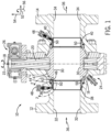
- FIG. 1 is a cross-sectional side view of a ball valve 10, in accordance with an embodiment.
- the ball valve 10 includes a housing, which is formed by an annular body 12 and an annular adapter 14.
- the body 12 and the adapter 14 of the ball valve 10 are configured to mate with each other such that a seal is created between the body 12 and the adapter 14.
- the ball valve 10 may be constructed with two adapters.
- the ball valve 10 includes a ball 16 configured to rotate between the illustrated open position 24 and a closed position about a rotational axis 18, as shown by arrow 22.
- the ball 16 is coupled to a stem 20 such that rotation of the stem 20 (e.g., via a hydraulic or pneumatic or electronic actuator or via a handle that may be operated manually) causes the ball 16 to rotate.
- the ball valve 10 In the open position 24, the ball valve 10 enables fluid flow through the ball valve 10. As shown, in the open position 24, a bore 30 of the ball 16 is aligned with a bore 32 of the body 12 and a bore 34 of the adapter 14, such that fluid may pass through the ball valve 10. In general, a fluid 36 may enter through either the body 12 or the adapter 14 and exit through the other. For example, in the illustrated embodiment, the fluid 36 enters the bore 32 of the body 12 from a first line or passageway, flows through the bore 30 of the ball 16, and exits the bore 34 of the adapter 14 into a second line or passageway.
- a cavity pressure within a cavity 47 of the ball valve 10 may be less than a line pressure in the bore 32 of the body 12.
- the ball valve 10 also includes two annular seats, a first seat 38 (e.g., a first annular seat or an upstream annular seat) positioned between the ball 16 and the body 12, and a second seat 40 (e.g., a second annular seat or a downstream annular seat) positioned between the ball 16 and the adapter 14.
- a first seat 38 e.g., a first annular seat or an upstream annular seat
- a second seat 40 e.g., a second annular seat or a downstream annular seat
- the first seat 38 includes a seal 42 (e.g., annular seal) along a first radially-outer surface 44 (e.g., radially-outermost surface) of the first seat 38 and/or one or more passageways 46 (e.g., axially-extending passageways).
- a seal 42 e.g., annular seal
- first radially-outer surface 44 e.g., radially-outermost surface
- passageways 46 e.g., axially-extending passageways.
- the seal 42 and the passageways 46 enable the first seat 38 to automatically, temporarily move away from the ball 16 upon an increase (e.g., a substantial increase, such as more than or approximately 10, 20, 30, 40, 50 percent increase compared to a baseline pressure within the cavity 47 while the ball valve 10 is moved from the closed position, and/or a sudden increase, such as more than or approximately 10, 20, 30, 40, 50 percent increase compared to the baseline pressure within the cavity 47 over a period of time, such as less than or approximately 5, 10, 20, or 30 seconds) in pressure within the cavity 47 of the ball valve 10 as the ball 16 rotates from the closed position toward the open position 24.
- an increase e.g., a substantial increase, such as more than or approximately 10, 20, 30, 40, 50 percent increase compared to a baseline pressure within the cavity 47 while the ball valve 10 is moved from the closed position
- a sudden increase such as more than or approximately 10, 20, 30, 40, 50 percent increase compared to the baseline pressure within the cavity 47 over a period of time, such as less than or approximately 5, 10, 20, or 30 seconds
- the first seat 38 automatically returns to its original position and/or moves toward the ball 16 as the pressure balances across the first seat 38 after a period of time and/or during further rotation of the ball 16 toward the open position 24.
- the first seat 38 is configured to self-adjust to temporarily provide a gap between the first seat 38 and the ball 16 of the ball valve 10, thereby reducing the torque needed to rotate the ball 16 over at least part of the stroke from the closed position toward the open position 24 and/or reducing wear on contacting surfaces of the ball 16 and/or the first seat 38, for example.
- the first seat 38 may move automatically without the use of external fluid sources (i.e., driven only by pressure changes caused by the movement of the fluid 36 within the ball valve 10, such as within the cavity 47 and the bores 30, 32, 34), complex electronic controllers, motors, and/or actuators, although in certain embodiments external fluid sources, complex electronic controllers, motors, and/or actuators, or the like may be utilized to supplement the techniques disclosed herein.
- external fluid sources i.e., driven only by pressure changes caused by the movement of the fluid 36 within the ball valve 10, such as within the cavity 47 and the bores 30, 32, 34
- complex electronic controllers, motors, and/or actuators although in certain embodiments external fluid sources, complex electronic controllers, motors, and/or actuators, or the like may be utilized to supplement the techniques disclosed herein.
- the ball valve 10 includes injection ports 48 that are configured to align with and enable fluid communication with injection channels 50 in the seats 38, 40.
- the injection ports 48 and injection channels 50 facilitate the delivery of lubricating or sealant fluids to the interfaces between the seats 38, 40 and the ball 16.
- the lubricating fluids reduce the frictional forces generated between the ball 16 and the seats 38, 40 when the ball 16 is rotated between the open position 24 and the closed position.
- the ball valve 10 and its components may be described with reference to an axial axis or direction 52, a radial axis or direction 54, and a circumferential axis or direction 56.
- FIG. 2 is a cross-sectional side view of a portion of the ball valve 10 of FIG. 1 taken within line 2-2.
- the ball valve 10 is in a closed position 58 (e.g., fully closed position).
- the bore 30 of the ball 16 is rotated perpendicular to the bores 32, 34 of the body 12 and the adapter 14, thereby substantially blocking the flow of the fluid 36 through the ball valve 10.
- a contacting surface 72 e.g., sealing face
- the contacting surface 72 is part of an insert 70 (e.g., annular insert or annular seal) coupled to a body 75 the first seat 38.
- the seal 76 and a main seal 78 e.g., annular seal
- the cavity pressure within the cavity 47 of the ball valve 10 is relieved or reduced (e.g., via a decrease in the pipeline downstream pressure or a valve or other pressure relief system).
- a pressure on a first side 59 (e.g., upstream side or in the bore 32 of the body 12) of the first seat 38 is higher than a pressure on a second side (e.g., downstream side or within the cavity 47 of the ball valve 10) of the first seat 38, which causes the first seat 38 to maintain contact with the ball 16.
- the fluid 36 exerts a force 62 on an axially-facing surface 60 (e.g., annular surface) of the first seat 38 and/or the fluid 36 travels through the injection channels 50, as shown by arrows 64, to exert a force 68 on an axially-facing surface 66 (e.g., annular surface) of the first seat 38 to drive the first seat 38 toward the ball 16.
- a spring force 61 exerted on the first seat 38 such as by a biasing member 63 (e.g., spring) positioned between opposed axially-facing surfaces of the body 12 and the first seat 38, may drive the first seat 38 toward the ball 16.
- a biasing member 63 e.g., spring
- a large differential pressure (e.g., more than 30, 50, 70, or 100 megapascals (MPa) and/or more than 10, 20, 30, 40, or 50 percent) may exist across the ball valve 10 when the ball valve 10 is in the closed position 58.
- MPa megapascals
- flow of the fluid 36 through the ball valve 10 may cause a high localized force at the interface between the first seat 38 and the ball 16 and/or cause the first seat 38 to be pushed into a slightly cocked or tilted position within the bore 30 of the ball 16, thereby damaging these components and/or increasing torque requirements for opening the ball valve 10.
- the disclosed embodiments advantageously provide features, such as the seal 42 in the radially-outer face 44 of the first seat 38 and the passageways 46, that cause the first seat 38 to automatically move away from the ball 16 as the ball valve 10 moves from the closed position 58 toward the open position 24.
- FIG. 3 is a cross-sectional top view of another portion of the ball valve 10 proximate to the portion of FIG. 2 .
- the cavity pressure within the cavity 47 of the ball valve 10 increases.
- the seal 42 is an annular seal that extends circumferentially along the radially-outer face 44 of the first seat 38.
- the seal 42 is configured to block fluid flow along the radially-outer face 44 of the first seat 38, thereby causing the cavity pressure to exert a force 84 on an axially-facing surface 86 of the first seat 38 that drives the first seat 38 away from the ball 16.
- the first seat 38 may be physically separated from (e.g., may not contact) the ball 16 by a gap 88 (e.g., annular gap) as the ball 16 rotates through a portion of its path between the closed position 58 and the open position 24.
- the first seat 38 and the ball 16 may be physically separated from one another for more than or approximately 0.5, 1, 5, 10, 30, or 60 seconds.
- the first seat 38 and the ball 16 may be physically separated from one another through at least about 5, 10, 15, 20, 25, 30, or 40 degrees of the stroke between the closed position 58 to the open position 24. Additionally or alternatively, the first seat 38 and the ball 16 may be physically separated from one another until the ball 16 is rotated to more than or approximately 5, 10, 15, 20, 25, or 30 degrees from the closed position 58. Such a configuration may desirably reduce torque needed to rotate the ball 16 and/or reduce wear on the contacting surfaces of the first seat 38 and the ball 16, for example.
- the body 12 includes a shoulder 89 (e.g., an annular axially-facing surface) that is configured to block and/or to limit axial movement of the first seat 38 relative to the body 12, which in turn may protect the spring 63.
- the force 84 exerted by the cavity pressure in the cavity 47 acts on a first surface area (e.g., the surface area of the axially-facing surface 86) that is substantially larger (e.g., more than or equal to approximately 10, 15, 20, 25, 30, 35, 40, 45, or 50 percent larger) than a second surface area (e.g., the surface area of the axially-facing surfaces 60, 66) on which the forces 62, 68 exerted by the line pressure act.
- the cavity pressure in the cavity 47 may nearly immediately drive the first seat 38 away from the ball 16.
- the first seat 38 includes the passageways 46.
- one or more passageways 46 extend through the body 75 of the first seat 38 and are positioned between the seal 42 and the main seal 78 along the radial axis 54.
- the one or more passageways 46 which extend along the axial axis 52, may be positioned at discrete locations circumferentially about the first seat 38.
- the one or more passageways 46 may have any suitable configuration that enables fluid to flow from the cavity 47 to a space 90 (e.g., annular space) on an opposite side of the first seat 38 from the cavity 47.
- the space 90 is defined between the body 12 and an axially-facing surface 92 of the first seat 38.
- the passageways 46 may have any suitable diameter, geometry, spacing, and/or number to adjust a timing and/or a speed of movement of the first seat 38.
- relatively smaller passageways 46 may cause the first seat 46 to remain separated from the ball 16 for a longer period of time than relatively larger passageways 46. Accordingly, the first seat 38 is automatically, temporarily separated from the ball 16 as the ball 16 is rotated from the closed position 58 toward the open position 24, and returns to contact the ball 16 once the pressure balances across the first seat 38.
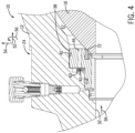
- FIG. 4 is a cross-sectional side view of the portion of the ball valve 10 of FIG. 2 .
- the ball valve 10 is in the open position 24.
- the pressures and forces across the first seat 38 including the spring force 61, drive the first seat 38 toward the ball 16 such that the contacting surface 72 of the first seat 38 contacts and forms the seal 76 with the ball 16.
- FIG. 5 is a cross-sectional side view of a portion of a ball valve 100 having an annular seat 102 (e.g., a double-piston annular seat).
- the ball valve 100 includes a ball 104 and the annular seat 102, which is positioned between the ball 104 and a body 106.
- the annular seat 102 includes a seal 108 (e.g., annular seal) along a first radially-outer surface 110 (e.g., radially-outermost surface) of the annular seat 102 and/or one or more passageways 112 (e.g., axially-extending passageways).
- a cartridge 114 e.g., annular cartridge
- the annular seat 102 is configured to automatically, temporarily move away from the ball 104 as the ball 104 rotates between the closed position and the open position, as discussed above with respect to FIGS. 1-4 .
Landscapes
- Engineering & Computer Science (AREA)
- General Engineering & Computer Science (AREA)
- Mechanical Engineering (AREA)
- Taps Or Cocks (AREA)
Description
- This section is intended to introduce the reader to various aspects of art that may be related to various aspects of the present invention, which are described and/or claimed below.
- Ball valves are employed to open or close to enable or block a flow of fluid in a variety of applications. Typical ball valves may include a body, an adapter, a rotatable ball disposed within the body and the adapter, and a stem coupled to the ball. Trunnion ball valves use seats that physically contact the ball of the ball valve. However, as the ball rotates within the ball valve from a closed position to an open position, the fluid under pressure drives the seat into the ball, thereby increasing torque needed to move the ball to the open position and/or causing wear on contacting surfaces of the ball and/or the seat, for example.
US 3.656.498 discloses a ball valve configured for preventing cocking.US 2006/0065314 A1 discloses a pigging ball valve with a housing and a ball core supported for rotation within the housing.WO 2015/086876 A1 discloses a cryogenic ball valve for opening or closing the passage of a fluid through an inlet or outlet duct.FR 2.981.720 A1 WO 2016/029689 A1 discloses a double-piston-effect valve. According to the invention, an improved ball valve is provided according to claim 1. - Various features, aspects, and advantages of the present invention will become better understood when the following detailed description is read with reference to the accompanying figures in which like characters represent like parts throughout the figures, wherein:
-
FIG. 1 is a cross-sectional side view of a ball valve, in accordance with an embodiment of the present disclosure; -
FIG. 2 is a cross-sectional side view of a portion of the ball valve ofFIG. 1 taken within line 2-2, wherein the ball valve is in a closed position; -
FIG. 3 is a cross-sectional top view of another portion of the ball valve proximate to the portion ofFIG. 2 , wherein the ball valve is between the closed position and an open position; -
FIG. 4 is a cross-sectional side view of the portion of the ball valve ofFIG. 2 , wherein the ball valve is in the open position; and -
FIG. 5 is a cross-sectional side view of a ball valve, in accordance with another embodiment of the present disclosure. - One or more specific embodiments of the present invention will be described below. These described embodiments are only exemplary of the present invention. Additionally, in an effort to provide a concise description of these exemplary embodiments, all features of an actual implementation may not be described in the specification. It should be appreciated that in the development of any such actual implementation, as in any engineering or design project, numerous implementation-specific decisions must be made to achieve the developers' specific goals, such as compliance with system-related and business-related constraints, which may vary from one implementation to another. Moreover, it should be appreciated that such a development effort might be complex and time consuming, but would nevertheless be a routine undertaking of design, fabrication, and manufacture for those of ordinary skill having the benefit of this disclosure.
- Certain embodiments of the present disclosure include a ball valve having an adjustable seat. In particular, the seat of the ball valve is configured to automatically move in response to changes in a pressure across the seat. The seat is configured to automatically move away from the ball upon an increase (e.g., a substantial and/or a sudden increase) in pressure within a cavity of the ball valve (e.g., upon rotating the ball from a fully closed position toward an open position). The seat then automatically returns to its original position and/or moves back toward the ball as the pressure balances across the seat. Thus, the disclosed seat may be configured to mechanically self-adjust to temporarily provide a gap between the seat and the ball of the ball valve without the use of external fluid sources, complex electronic controllers, motors, and/or actuators, although in certain embodiments external fluid sources, complex electronic controllers, motors, and/or actuators, or the like may be utilized to supplement the techniques disclosed herein. The ball valve may be utilized as part of any suitable fluid-handling system, such as an energy-acquisition or processing system (e.g., a hydrocarbon-production or processing system, such as a subsea or surface oil or gas well, a pipeline, a natural-gas processing terminal, a refinery, or a natural-gas powered electrical plant, or the like).
- Turning now to the figures,
FIG. 1 is a cross-sectional side view of aball valve 10, in accordance with an embodiment. Theball valve 10 includes a housing, which is formed by anannular body 12 and anannular adapter 14. In the illustrated embodiment, thebody 12 and theadapter 14 of theball valve 10 are configured to mate with each other such that a seal is created between thebody 12 and theadapter 14. Theball valve 10 may be constructed with two adapters. Theball valve 10 includes aball 16 configured to rotate between the illustratedopen position 24 and a closed position about arotational axis 18, as shown byarrow 22. As shown, theball 16 is coupled to astem 20 such that rotation of the stem 20 (e.g., via a hydraulic or pneumatic or electronic actuator or via a handle that may be operated manually) causes theball 16 to rotate. - In the
open position 24, theball valve 10 enables fluid flow through theball valve 10. As shown, in theopen position 24, abore 30 of theball 16 is aligned with abore 32 of thebody 12 and abore 34 of theadapter 14, such that fluid may pass through theball valve 10. In general, afluid 36 may enter through either thebody 12 or theadapter 14 and exit through the other. For example, in the illustrated embodiment, thefluid 36 enters thebore 32 of thebody 12 from a first line or passageway, flows through thebore 30 of theball 16, and exits thebore 34 of theadapter 14 into a second line or passageway. In the closed position, thebore 30 of theball 16 is rotated perpendicular to thebores body 12 and theadapter 14, thereby substantially blocking the flow of thefluid 36 through theball valve 10. As discussed in more detail below, in the closed position, a cavity pressure within acavity 47 of theball valve 10 may be less than a line pressure in thebore 32 of thebody 12. - As illustrated in
FIG. 1 , theball valve 10 also includes two annular seats, a first seat 38 (e.g., a first annular seat or an upstream annular seat) positioned between theball 16 and thebody 12, and a second seat 40 (e.g., a second annular seat or a downstream annular seat) positioned between theball 16 and theadapter 14. During operation of theball valve 10, theseats ball 16 and thebody 12 and between theball 16 and theadapter 14. Thefirst seat 38 includes a seal 42 (e.g., annular seal) along a first radially-outer surface 44 (e.g., radially-outermost surface) of thefirst seat 38 and/or one or more passageways 46 (e.g., axially-extending passageways). - As discussed in more detail below, the
seal 42 and thepassageways 46 enable thefirst seat 38 to automatically, temporarily move away from theball 16 upon an increase (e.g., a substantial increase, such as more than or approximately 10, 20, 30, 40, 50 percent increase compared to a baseline pressure within thecavity 47 while theball valve 10 is moved from the closed position, and/or a sudden increase, such as more than or approximately 10, 20, 30, 40, 50 percent increase compared to the baseline pressure within thecavity 47 over a period of time, such as less than or approximately 5, 10, 20, or 30 seconds) in pressure within thecavity 47 of theball valve 10 as theball 16 rotates from the closed position toward theopen position 24. Thefirst seat 38 automatically returns to its original position and/or moves toward theball 16 as the pressure balances across thefirst seat 38 after a period of time and/or during further rotation of theball 16 toward theopen position 24. Thus, thefirst seat 38 is configured to self-adjust to temporarily provide a gap between thefirst seat 38 and theball 16 of theball valve 10, thereby reducing the torque needed to rotate theball 16 over at least part of the stroke from the closed position toward theopen position 24 and/or reducing wear on contacting surfaces of theball 16 and/or thefirst seat 38, for example. In certain embodiments, thefirst seat 38 may move automatically without the use of external fluid sources (i.e., driven only by pressure changes caused by the movement of thefluid 36 within theball valve 10, such as within thecavity 47 and thebores - In certain embodiments, the
ball valve 10 includesinjection ports 48 that are configured to align with and enable fluid communication withinjection channels 50 in theseats injection ports 48 andinjection channels 50 facilitate the delivery of lubricating or sealant fluids to the interfaces between theseats ball 16. The lubricating fluids reduce the frictional forces generated between theball 16 and theseats ball 16 is rotated between theopen position 24 and the closed position. To facilitate discussion, theball valve 10 and its components may be described with reference to an axial axis ordirection 52, a radial axis ordirection 54, and a circumferential axis ordirection 56. -
FIG. 2 is a cross-sectional side view of a portion of theball valve 10 ofFIG. 1 taken within line 2-2. In the illustrated embodiment, theball valve 10 is in a closed position 58 (e.g., fully closed position). In the closedposition 58, thebore 30 of theball 16 is rotated perpendicular to thebores body 12 and theadapter 14, thereby substantially blocking the flow of thefluid 36 through theball valve 10. Furthermore, when theball valve 10 is in the closedposition 58, a contacting surface 72 (e.g., sealing face) of thefirst seat 38 contacts anouter surface 74 of theball 16 and forms aseal 76 with theball 16. In certain embodiments, the contactingsurface 72 is part of an insert 70 (e.g., annular insert or annular seal) coupled to abody 75 thefirst seat 38. - When the
ball valve 10 is in the closedposition 58, theseal 76 and a main seal 78 (e.g., annular seal) substantially block a flow of thefluid 36 across thefirst seat 38. In certain circumstances, after theball valve 10 reaches the closedposition 58, the cavity pressure within thecavity 47 of theball valve 10 is relieved or reduced (e.g., via a decrease in the pipeline downstream pressure or a valve or other pressure relief system). Accordingly, a pressure on a first side 59 (e.g., upstream side or in thebore 32 of the body 12) of thefirst seat 38 is higher than a pressure on a second side (e.g., downstream side or within thecavity 47 of the ball valve 10) of thefirst seat 38, which causes thefirst seat 38 to maintain contact with theball 16. Thefluid 36 exerts aforce 62 on an axially-facing surface 60 (e.g., annular surface) of thefirst seat 38 and/or thefluid 36 travels through theinjection channels 50, as shown byarrows 64, to exert aforce 68 on an axially-facing surface 66 (e.g., annular surface) of thefirst seat 38 to drive thefirst seat 38 toward theball 16. Additionally or alternatively, aspring force 61 exerted on thefirst seat 38, such as by a biasing member 63 (e.g., spring) positioned between opposed axially-facing surfaces of thebody 12 and thefirst seat 38, may drive thefirst seat 38 toward theball 16. - In certain circumstances, a large differential pressure (e.g., more than 30, 50, 70, or 100 megapascals (MPa) and/or more than 10, 20, 30, 40, or 50 percent) may exist across the
ball valve 10 when theball valve 10 is in the closedposition 58. Without the disclosed embodiments, while rotating theball valve 10 from theclosed position 58 toward the open position 24 (e.g., from the fullyclosed position 58 to approximately 20 to 25 degrees open), flow of the fluid 36 through theball valve 10 may cause a high localized force at the interface between thefirst seat 38 and theball 16 and/or cause thefirst seat 38 to be pushed into a slightly cocked or tilted position within thebore 30 of theball 16, thereby damaging these components and/or increasing torque requirements for opening theball valve 10. As discussed in more detail below, the disclosed embodiments advantageously provide features, such as theseal 42 in the radially-outer face 44 of thefirst seat 38 and thepassageways 46, that cause thefirst seat 38 to automatically move away from theball 16 as theball valve 10 moves from theclosed position 58 toward theopen position 24. -
FIG. 3 is a cross-sectional top view of another portion of theball valve 10 proximate to the portion ofFIG. 2 . As theball valve 10 moves from theclosed position 58 toward the open position 24 (e.g., to the illustratedintermediate position 82, which may be less than or equal to approximately 5, 10, 15, 20, 25, 30, 40, 50, or 60 degrees from theclosed position 58, or between about 5 to 40, 10 to 25, or 15 to 20 degrees from the closed position 58), the cavity pressure within thecavity 47 of theball valve 10 increases. Theseal 42 is an annular seal that extends circumferentially along the radially-outer face 44 of thefirst seat 38. Theseal 42 is configured to block fluid flow along the radially-outer face 44 of thefirst seat 38, thereby causing the cavity pressure to exert aforce 84 on an axially-facingsurface 86 of thefirst seat 38 that drives thefirst seat 38 away from theball 16. Thus, in the disclosed embodiments, thefirst seat 38 may be physically separated from (e.g., may not contact) theball 16 by a gap 88 (e.g., annular gap) as theball 16 rotates through a portion of its path between theclosed position 58 and theopen position 24. In some embodiments, thefirst seat 38 and theball 16 may be physically separated from one another for more than or approximately 0.5, 1, 5, 10, 30, or 60 seconds. In some embodiments, thefirst seat 38 and theball 16 may be physically separated from one another through at least about 5, 10, 15, 20, 25, 30, or 40 degrees of the stroke between theclosed position 58 to theopen position 24. Additionally or alternatively, thefirst seat 38 and theball 16 may be physically separated from one another until theball 16 is rotated to more than or approximately 5, 10, 15, 20, 25, or 30 degrees from theclosed position 58. Such a configuration may desirably reduce torque needed to rotate theball 16 and/or reduce wear on the contacting surfaces of thefirst seat 38 and theball 16, for example. - As shown, the
body 12 includes a shoulder 89 (e.g., an annular axially-facing surface) that is configured to block and/or to limit axial movement of thefirst seat 38 relative to thebody 12, which in turn may protect thespring 63. In the illustrated embodiment, theforce 84 exerted by the cavity pressure in thecavity 47 acts on a first surface area (e.g., the surface area of the axially-facing surface 86) that is substantially larger (e.g., more than or equal to approximately 10, 15, 20, 25, 30, 35, 40, 45, or 50 percent larger) than a second surface area (e.g., the surface area of the axially-facingsurfaces 60, 66) on which theforces ball 16 to theintermediate position 82 from theclosed position 58, the cavity pressure in thecavity 47 may nearly immediately drive thefirst seat 38 away from theball 16. - In the illustrated embodiment, the
first seat 38 includes thepassageways 46. In certain embodiments, one ormore passageways 46 extend through thebody 75 of thefirst seat 38 and are positioned between theseal 42 and themain seal 78 along theradial axis 54. The one ormore passageways 46, which extend along theaxial axis 52, may be positioned at discrete locations circumferentially about thefirst seat 38. The one ormore passageways 46 may have any suitable configuration that enables fluid to flow from thecavity 47 to a space 90 (e.g., annular space) on an opposite side of thefirst seat 38 from thecavity 47. In the illustrated embodiment, thespace 90 is defined between thebody 12 and an axially-facingsurface 92 of thefirst seat 38. Such a configuration enables pressure to increase in thespace 90 over time, thereby eventually causing pressure balance across thefirst seat 38 and enabling thefirst seat 38 to move back toward theball 16. Thepassageways 46 may have any suitable diameter, geometry, spacing, and/or number to adjust a timing and/or a speed of movement of thefirst seat 38. For example, relativelysmaller passageways 46 may cause thefirst seat 46 to remain separated from theball 16 for a longer period of time than relativelylarger passageways 46. Accordingly, thefirst seat 38 is automatically, temporarily separated from theball 16 as theball 16 is rotated from theclosed position 58 toward theopen position 24, and returns to contact theball 16 once the pressure balances across thefirst seat 38. -
FIG. 4 is a cross-sectional side view of the portion of theball valve 10 ofFIG. 2 . In the illustrated embodiment, theball valve 10 is in theopen position 24. In theopen position 24, the pressures and forces across thefirst seat 38, including thespring force 61, drive thefirst seat 38 toward theball 16 such that the contactingsurface 72 of thefirst seat 38 contacts and forms theseal 76 with theball 16. - It should be understood that the features disclosed above with respect to
FIGS. 1-4 may be adapted for use with other types of ball valves or annular seats of various constructions. For example,FIG. 5 is a cross-sectional side view of a portion of aball valve 100 having an annular seat 102 (e.g., a double-piston annular seat). In the illustrated embodiment, theball valve 100 includes aball 104 and theannular seat 102, which is positioned between theball 104 and abody 106. Theannular seat 102 includes a seal 108 (e.g., annular seal) along a first radially-outer surface 110 (e.g., radially-outermost surface) of theannular seat 102 and/or one or more passageways 112 (e.g., axially-extending passageways). In the illustrated embodiment, a cartridge 114 (e.g., annular cartridge) is positioned along a radially-outer surface 116 of theannular seat 102 and may support one or more sealing rings 120. Thus, theannular seat 102 is configured to automatically, temporarily move away from theball 104 as theball 104 rotates between the closed position and the open position, as discussed above with respect toFIGS. 1-4 . - While the invention may be susceptible to various modifications and alternative forms, specific embodiments have been shown by way of example in the drawings and have been described in detail herein. However, it should be understood that the invention is not intended to be limited to the particular forms disclosed. Rather, the invention is to cover all modifications, equivalents, and alternatives falling within the scope of the invention as defined by the following appended claims.
Claims (10)
- A ball valve (10,100) positioned between a first line (59) and a second line, comprising:a housing (12);a ball (16, 104) disposed within the housing (12) and having a bore (30), wherein the ball is configured to rotate between an open position and a closed position;an annular seat (38, 102) disposed between the housing (12) and the ball, (16, 104) wherein the annular seat comprises:a first surface area (86) exposed to a cavity pressure in the valve cavity and a second surface area (60) exposed to a line pressure in the first line (59);a first annular sealing ring (42, 108) extending circumferentially about a radially-outer surface (44, 110) of the annular seat (38, 102) and configured to form an annular seal between the radially-outer surface (44, 116) of the annular seat (38, 102) and the housing (12) in between the valve cavity (47) and an annular space (90) between the annular seat and the housing and block fluid flow from the valve cavity (47) to the annular space (90); andan axially-extending passageway (46, 112) extending through the annular seat (38, 102) to enable fluid flow from the valve cavity (47) to the annular space (90) between the annular seat and the housing,characterised in that:the first surface area is at least 10 percent greater than the second surface area,the first surface area, the second surface area, and the first annular sealing ring enable an increase in pressure in the cavity (47) of the ball valve acting on the first surface area (86) to move the annular seat (38, 102) away from the ball (16, 104) as the ball rotates from the closed position toward the open position, andfluid flow from the valve cavity (47) through the axially extending passageway (46, 112) into the annular space (90)-increases pressure in the annular space, thereby eventually causes pressure balance across the annular seat (38,102) and enables the annular seat (38, 102) to move back towards the ball (16, 104).
- The ball valve (10, 100) of claim 1, wherein the first annular sealing ring (42, 108) extends circumferentially about a radially-outermost portion of the radially-outer surface (44, 110) of the annular seat (38, 102).
- The ball valve (10, 100) of claim 2, comprising a second annular sealing ring (78, 120) extending circumferentially about the radially-outer surface of the annular seat (38, 102), wherein the second annular sealing ring is configured to block the flow of working fluid from the first line (59) to the annular space (90) between the annular seat (38, 102) and the housing (12).
- The ball valve (10, 100) of claim 3, wherein the axially-extending passageway (46, 112) is positioned between the first annular sealing ring (42, 108) and the second annular sealing ring (78, 120) along a radial axis of the ball valve.
- The ball valve (10, 100) of any one of claims 1-4, comprising one or more additional axially-extending passageways (46, 112) extending from the valve cavity (47) to the annular space (90) and positioned at discrete circumferential locations about the annular seat (38, 102).
- The ball valve of any one of claims 1-5, comprising a biasing member (63) positioned in the annular space (90), wherein the biasing member is configured to bias the annular seat toward the ball (16, 104).
- The ball valve (10, 100) of claim 6, comprising a shoulder (89) extending from the housing (12) and configured to limit the movement of the annular seat (38, 102), thereby protecting the biasing member (63).
- The ball valve (10, 100) of any one of claims 1-7, wherein the first surface area, the second surface area, the first annular sealing ring (42, 108), the axially-extending passageway (46, 112), and the annular space (90) facilitate temporary movement of the annular seat (38, 102) away from the ball (16, 104) while the ball moves through at least a portion of a path between approximately 5 and 40 degrees from the closed position.
- The ball valve of any one of claims 1-8, wherein the first surface area is at least 25 percent greater than the second surface area.
- The ball valve (110) of claim 1 comprising an annular cartridge (114) positioned along a radially-outer surface (116) of the annular seat (102) and supporting one or more sealing rings (120).
Applications Claiming Priority (2)
| Application Number | Priority Date | Filing Date | Title |
|---|---|---|---|
| US15/231,945 US10794496B2 (en) | 2016-08-09 | 2016-08-09 | Ball valve system |
| PCT/US2017/046171 WO2018031699A1 (en) | 2016-08-09 | 2017-08-09 | Ball valve system |
Publications (2)
| Publication Number | Publication Date |
|---|---|
| EP3497356A1 EP3497356A1 (en) | 2019-06-19 |
| EP3497356B1 true EP3497356B1 (en) | 2024-06-26 |
Family
ID=59677381
Family Applications (1)
| Application Number | Title | Priority Date | Filing Date |
|---|---|---|---|
| EP17754953.2A Active EP3497356B1 (en) | 2016-08-09 | 2017-08-09 | Ball valve system |
Country Status (4)
| Country | Link |
|---|---|
| US (1) | US10794496B2 (en) |
| EP (1) | EP3497356B1 (en) |
| CN (1) | CN109790943B (en) |
| WO (1) | WO2018031699A1 (en) |
Families Citing this family (10)
| Publication number | Priority date | Publication date | Assignee | Title |
|---|---|---|---|---|
| US12259064B2 (en) | 2018-11-01 | 2025-03-25 | Oil States Energy Services, L.L.C. | Valve with pressure differential seating |
| US11047485B2 (en) * | 2019-08-08 | 2021-06-29 | Saudi Arabian Oil Company | Sealing a gate valve |
| CN112984146B (en) * | 2021-02-05 | 2023-01-13 | 陕西蓝箭航天技术有限公司 | Ball valve device for liquid rocket engine |
| CN114893581A (en) * | 2022-05-23 | 2022-08-12 | 烟台杰瑞石油装备技术有限公司 | Plug valve and fracturing equipment |
| US20250035219A1 (en) * | 2022-06-28 | 2025-01-30 | Zp Interests, Llc | Pressure energized gate valve seat and seal assembly |
| US12110979B1 (en) * | 2022-06-28 | 2024-10-08 | Zp Interests, Llc | Pressure energized gate valve seat and seal assembly |
| CN115614497B (en) * | 2022-10-14 | 2025-06-06 | 华英阀业有限公司 | A new type of high-pressure pipeline ball valve |
| CN115929937A (en) * | 2022-12-28 | 2023-04-07 | 四川凯茨阀门制造有限公司 | A cast steel fixed ball valve structure |
| US12510167B2 (en) * | 2024-02-29 | 2025-12-30 | SCV Valve, LLC | Systems and methods for double piston effect ball valves |
| CN118775576B (en) * | 2024-07-31 | 2025-04-04 | 浙江安腾阀门有限公司 | A two-stage metal hard seal ball valve |
Citations (3)
| Publication number | Priority date | Publication date | Assignee | Title |
|---|---|---|---|---|
| GB2204666A (en) * | 1987-05-05 | 1988-11-16 | Worcester Controls | Ball-valve seat ring |
| CA2218030A1 (en) * | 1997-10-10 | 1999-04-10 | Walter Domytrak | Valve having pressure equalizing conduit |
| WO2015162581A1 (en) * | 2014-04-23 | 2015-10-29 | Broen Oil & Gas Sp.Z.O.O | A valve, and a method for effectively sealing an area between two surfaces in a valve and use thereof |
Family Cites Families (36)
| Publication number | Priority date | Publication date | Assignee | Title |
|---|---|---|---|---|
| US3378026A (en) * | 1964-03-26 | 1968-04-16 | Cameron Iron Works Inc | Lubricated valve with means to relieve excessive sealant pressure |
| US3379410A (en) * | 1965-03-11 | 1968-04-23 | Acf Ind Inc | Valve having seat seal and venting means |
| US3416558A (en) * | 1967-01-23 | 1968-12-17 | Acf Ind Inc | Spherical plug valve having lubricated seats |
| US3463448A (en) | 1967-11-24 | 1969-08-26 | Grove Valve & Regulator Co | Flow blocking device with pressure seal means |
| US3656498A (en) * | 1971-01-04 | 1972-04-18 | M & J Valve Co | Ball valve |
| US3667727A (en) * | 1971-05-10 | 1972-06-06 | Billy W Bowden | Seat for ball or gate valves |
| US3695579A (en) * | 1971-06-01 | 1972-10-03 | Herbert Allen | Valve |
| US3760833A (en) * | 1972-03-14 | 1973-09-25 | Acf Ind Inc | Sealing means for valve structure |
| US3749357A (en) * | 1972-04-07 | 1973-07-31 | Acf Ind Inc | Valve structure having fluid pressure actuated seats |
| US3752178A (en) * | 1972-05-15 | 1973-08-14 | M & J Valve Co | Valve construction |
| US3784155A (en) * | 1973-04-13 | 1974-01-08 | Acf Ind Inc | Ball and seat arrangement for ball valve |
| US3856261A (en) * | 1973-08-02 | 1974-12-24 | Acf Ind Inc | Pressure relief means for valve body chamber |
| US4084608A (en) * | 1976-07-01 | 1978-04-18 | Constructions Metalliques De Provence | Cocks having rotating valves and sliding seats |
| US4083376A (en) * | 1976-10-14 | 1978-04-11 | Acf Industries, Incorporated | Two piece double acting valve seat assembly |
| GB1525193A (en) * | 1976-11-13 | 1978-09-20 | Tk Valve Ltd | Ball valves |
| US4135545A (en) * | 1977-08-05 | 1979-01-23 | Acf Industries, Incorporated | Ball valve seat assembly having a swaged seat ring to retain the face seal |
| US4254793A (en) * | 1979-01-15 | 1981-03-10 | Domer Scaramucci | Ball valve having valve chamber venting seal assemblies |
| CA1108589A (en) * | 1979-06-01 | 1981-09-08 | Grove Valve And Regulator Company | Fire safe seal |
| US4286614A (en) * | 1979-09-19 | 1981-09-01 | Acf Industries, Incorporated | High temperature ball valve |
| US4280522A (en) * | 1980-04-14 | 1981-07-28 | Rockwell International Corporation | Fire seal for valves |
| US4477055A (en) * | 1983-06-30 | 1984-10-16 | Acf Industries, Incorporated | Valve seat for ball valves |
| FI72584C (en) * | 1985-09-04 | 1987-06-08 | Neles Oy | VENTIL. |
| DE4423801C1 (en) * | 1994-07-01 | 1995-11-23 | Borsig Kugelhahn Gmbh | Device for sealing shut-off devices arranged in lines for the conveyance of liquids or gases |
| US6082707A (en) * | 1998-10-23 | 2000-07-04 | Gulf Technologies International, L.C. | Valve seat and method |
| CA2480501C (en) | 2004-09-28 | 2011-03-29 | Argus Machine Co. Ltd. | Pigging ball valve |
| EP2341269A1 (en) * | 2009-12-22 | 2011-07-06 | Valbart S.r.l. | Trunnion-mounted ball valve with reverse-piston effect |
| US8496226B2 (en) * | 2010-04-30 | 2013-07-30 | Fisher Controls International Llc | Floating ball valve seal with bellows and C-seal |
| US9657848B2 (en) * | 2011-01-03 | 2017-05-23 | Cameron International Corporation | Trunnion ball valve with interchangeable and replaceable seat insert |
| US9777841B2 (en) * | 2011-01-03 | 2017-10-03 | Cameron International Corporation | Trunnion ball valve seat with V-section spring |
| KR20140008410A (en) * | 2011-02-22 | 2014-01-21 | 스와겔로크 컴패니 | Ball valves and associated methods |
| WO2013021238A1 (en) * | 2011-08-08 | 2013-02-14 | Gasket International S.P.A. | Sealing system for industrial valves, particularly for ball valves, and valve comprising said system |
| FR2981720A1 (en) | 2011-10-25 | 2013-04-26 | Total Sa | ISOLATION TAP |
| US9140369B2 (en) | 2013-10-15 | 2015-09-22 | Fisher Controls International Llc | Floating ball valve seal |
| ES2483090B1 (en) | 2013-12-11 | 2015-05-11 | Valvospain, S.L. | Guided cryogenic ball valve |
| CN204140929U (en) * | 2014-08-26 | 2015-02-04 | 庆堂工业股份有限公司 | Novel double-piston effect valve |
| US9328828B1 (en) * | 2014-11-21 | 2016-05-03 | Valve Innovations, Llc | Seat assembly for valve |
-
2016
- 2016-08-09 US US15/231,945 patent/US10794496B2/en active Active
-
2017
- 2017-08-09 CN CN201780054810.7A patent/CN109790943B/en active Active
- 2017-08-09 EP EP17754953.2A patent/EP3497356B1/en active Active
- 2017-08-09 WO PCT/US2017/046171 patent/WO2018031699A1/en not_active Ceased
Patent Citations (3)
| Publication number | Priority date | Publication date | Assignee | Title |
|---|---|---|---|---|
| GB2204666A (en) * | 1987-05-05 | 1988-11-16 | Worcester Controls | Ball-valve seat ring |
| CA2218030A1 (en) * | 1997-10-10 | 1999-04-10 | Walter Domytrak | Valve having pressure equalizing conduit |
| WO2015162581A1 (en) * | 2014-04-23 | 2015-10-29 | Broen Oil & Gas Sp.Z.O.O | A valve, and a method for effectively sealing an area between two surfaces in a valve and use thereof |
Also Published As
| Publication number | Publication date |
|---|---|
| EP3497356A1 (en) | 2019-06-19 |
| CN109790943B (en) | 2022-07-19 |
| CN109790943A (en) | 2019-05-21 |
| WO2018031699A1 (en) | 2018-02-15 |
| US20180045324A1 (en) | 2018-02-15 |
| US10794496B2 (en) | 2020-10-06 |
Similar Documents
| Publication | Publication Date | Title |
|---|---|---|
| US10794496B2 (en) | Ball valve system | |
| RU2696167C1 (en) | Sealing devices for high pressure flow control | |
| EP3040588B1 (en) | Double piston effect lip seal seating assemblies | |
| US8960643B2 (en) | Double offset ball member usable in ball valves and other flow control applications | |
| US10890263B2 (en) | Fluid flow control apparatus for use with fluid valves | |
| KR20140008410A (en) | Ball valves and associated methods | |
| EP3167212A1 (en) | Valve assemblies, valve seats including flexible arms, and related methods | |
| US7249768B2 (en) | Shaft seal assembly and method | |
| EP3537013B1 (en) | Bearing for rotary control valve | |
| EP3282156A1 (en) | Ball valve system and method | |
| KR102501862B1 (en) | High frequency ball valve | |
| WO2024140526A1 (en) | Valve device | |
| CN118843760A (en) | Sealing system, machine and method with additional pressure protection |
Legal Events
| Date | Code | Title | Description |
|---|---|---|---|
| STAA | Information on the status of an ep patent application or granted ep patent |
Free format text: STATUS: UNKNOWN |
|
| STAA | Information on the status of an ep patent application or granted ep patent |
Free format text: STATUS: THE INTERNATIONAL PUBLICATION HAS BEEN MADE |
|
| PUAI | Public reference made under article 153(3) epc to a published international application that has entered the european phase |
Free format text: ORIGINAL CODE: 0009012 |
|
| STAA | Information on the status of an ep patent application or granted ep patent |
Free format text: STATUS: REQUEST FOR EXAMINATION WAS MADE |
|
| 17P | Request for examination filed |
Effective date: 20190305 |
|
| AK | Designated contracting states |
Kind code of ref document: A1 Designated state(s): AL AT BE BG CH CY CZ DE DK EE ES FI FR GB GR HR HU IE IS IT LI LT LU LV MC MK MT NL NO PL PT RO RS SE SI SK SM TR |
|
| AX | Request for extension of the european patent |
Extension state: BA ME |
|
| DAV | Request for validation of the european patent (deleted) | ||
| DAX | Request for extension of the european patent (deleted) | ||
| STAA | Information on the status of an ep patent application or granted ep patent |
Free format text: STATUS: EXAMINATION IS IN PROGRESS |
|
| 17Q | First examination report despatched |
Effective date: 20200117 |
|
| GRAP | Despatch of communication of intention to grant a patent |
Free format text: ORIGINAL CODE: EPIDOSNIGR1 |
|
| STAA | Information on the status of an ep patent application or granted ep patent |
Free format text: STATUS: GRANT OF PATENT IS INTENDED |
|
| INTG | Intention to grant announced |
Effective date: 20240221 |
|
| GRAS | Grant fee paid |
Free format text: ORIGINAL CODE: EPIDOSNIGR3 |
|
| GRAA | (expected) grant |
Free format text: ORIGINAL CODE: 0009210 |
|
| STAA | Information on the status of an ep patent application or granted ep patent |
Free format text: STATUS: THE PATENT HAS BEEN GRANTED |
|
| AK | Designated contracting states |
Kind code of ref document: B1 Designated state(s): AL AT BE BG CH CY CZ DE DK EE ES FI FR GB GR HR HU IE IS IT LI LT LU LV MC MK MT NL NO PL PT RO RS SE SI SK SM TR |
|
| REG | Reference to a national code |
Ref country code: GB Ref legal event code: FG4D |
|
| REG | Reference to a national code |
Ref country code: CH Ref legal event code: EP |
|
| REG | Reference to a national code |
Ref country code: DE Ref legal event code: R096 Ref document number: 602017082814 Country of ref document: DE |
|
| PG25 | Lapsed in a contracting state [announced via postgrant information from national office to epo] |
Ref country code: BG Free format text: LAPSE BECAUSE OF FAILURE TO SUBMIT A TRANSLATION OF THE DESCRIPTION OR TO PAY THE FEE WITHIN THE PRESCRIBED TIME-LIMIT Effective date: 20240626 |
|
| PG25 | Lapsed in a contracting state [announced via postgrant information from national office to epo] |
Ref country code: FI Free format text: LAPSE BECAUSE OF FAILURE TO SUBMIT A TRANSLATION OF THE DESCRIPTION OR TO PAY THE FEE WITHIN THE PRESCRIBED TIME-LIMIT Effective date: 20240626 Ref country code: HR Free format text: LAPSE BECAUSE OF FAILURE TO SUBMIT A TRANSLATION OF THE DESCRIPTION OR TO PAY THE FEE WITHIN THE PRESCRIBED TIME-LIMIT Effective date: 20240626 |
|
| REG | Reference to a national code |
Ref country code: LT Ref legal event code: MG9D |
|
| PG25 | Lapsed in a contracting state [announced via postgrant information from national office to epo] |
Ref country code: GR Free format text: LAPSE BECAUSE OF FAILURE TO SUBMIT A TRANSLATION OF THE DESCRIPTION OR TO PAY THE FEE WITHIN THE PRESCRIBED TIME-LIMIT Effective date: 20240927 |
|
| PG25 | Lapsed in a contracting state [announced via postgrant information from national office to epo] |
Ref country code: LV Free format text: LAPSE BECAUSE OF FAILURE TO SUBMIT A TRANSLATION OF THE DESCRIPTION OR TO PAY THE FEE WITHIN THE PRESCRIBED TIME-LIMIT Effective date: 20240626 |
|
| REG | Reference to a national code |
Ref country code: NL Ref legal event code: MP Effective date: 20240626 |
|
| PG25 | Lapsed in a contracting state [announced via postgrant information from national office to epo] |
Ref country code: LV Free format text: LAPSE BECAUSE OF FAILURE TO SUBMIT A TRANSLATION OF THE DESCRIPTION OR TO PAY THE FEE WITHIN THE PRESCRIBED TIME-LIMIT Effective date: 20240626 Ref country code: HR Free format text: LAPSE BECAUSE OF FAILURE TO SUBMIT A TRANSLATION OF THE DESCRIPTION OR TO PAY THE FEE WITHIN THE PRESCRIBED TIME-LIMIT Effective date: 20240626 Ref country code: GR Free format text: LAPSE BECAUSE OF FAILURE TO SUBMIT A TRANSLATION OF THE DESCRIPTION OR TO PAY THE FEE WITHIN THE PRESCRIBED TIME-LIMIT Effective date: 20240927 Ref country code: FI Free format text: LAPSE BECAUSE OF FAILURE TO SUBMIT A TRANSLATION OF THE DESCRIPTION OR TO PAY THE FEE WITHIN THE PRESCRIBED TIME-LIMIT Effective date: 20240626 Ref country code: BG Free format text: LAPSE BECAUSE OF FAILURE TO SUBMIT A TRANSLATION OF THE DESCRIPTION OR TO PAY THE FEE WITHIN THE PRESCRIBED TIME-LIMIT Effective date: 20240626 Ref country code: RS Free format text: LAPSE BECAUSE OF FAILURE TO SUBMIT A TRANSLATION OF THE DESCRIPTION OR TO PAY THE FEE WITHIN THE PRESCRIBED TIME-LIMIT Effective date: 20240926 |
|
| PG25 | Lapsed in a contracting state [announced via postgrant information from national office to epo] |
Ref country code: NL Free format text: LAPSE BECAUSE OF FAILURE TO SUBMIT A TRANSLATION OF THE DESCRIPTION OR TO PAY THE FEE WITHIN THE PRESCRIBED TIME-LIMIT Effective date: 20240626 |
|
| REG | Reference to a national code |
Ref country code: AT Ref legal event code: MK05 Ref document number: 1697970 Country of ref document: AT Kind code of ref document: T Effective date: 20240626 |
|
| PG25 | Lapsed in a contracting state [announced via postgrant information from national office to epo] |
Ref country code: NL Free format text: LAPSE BECAUSE OF FAILURE TO SUBMIT A TRANSLATION OF THE DESCRIPTION OR TO PAY THE FEE WITHIN THE PRESCRIBED TIME-LIMIT Effective date: 20240626 |
|
| PG25 | Lapsed in a contracting state [announced via postgrant information from national office to epo] |
Ref country code: PT Free format text: LAPSE BECAUSE OF FAILURE TO SUBMIT A TRANSLATION OF THE DESCRIPTION OR TO PAY THE FEE WITHIN THE PRESCRIBED TIME-LIMIT Effective date: 20241028 |
|
| PG25 | Lapsed in a contracting state [announced via postgrant information from national office to epo] |
Ref country code: PT Free format text: LAPSE BECAUSE OF FAILURE TO SUBMIT A TRANSLATION OF THE DESCRIPTION OR TO PAY THE FEE WITHIN THE PRESCRIBED TIME-LIMIT Effective date: 20241028 |
|
| PG25 | Lapsed in a contracting state [announced via postgrant information from national office to epo] |
Ref country code: PL Free format text: LAPSE BECAUSE OF FAILURE TO SUBMIT A TRANSLATION OF THE DESCRIPTION OR TO PAY THE FEE WITHIN THE PRESCRIBED TIME-LIMIT Effective date: 20240626 |
|
| PG25 | Lapsed in a contracting state [announced via postgrant information from national office to epo] |
Ref country code: EE Free format text: LAPSE BECAUSE OF FAILURE TO SUBMIT A TRANSLATION OF THE DESCRIPTION OR TO PAY THE FEE WITHIN THE PRESCRIBED TIME-LIMIT Effective date: 20240626 |
|
| PG25 | Lapsed in a contracting state [announced via postgrant information from national office to epo] |
Ref country code: IS Free format text: LAPSE BECAUSE OF FAILURE TO SUBMIT A TRANSLATION OF THE DESCRIPTION OR TO PAY THE FEE WITHIN THE PRESCRIBED TIME-LIMIT Effective date: 20241026 Ref country code: AT Free format text: LAPSE BECAUSE OF FAILURE TO SUBMIT A TRANSLATION OF THE DESCRIPTION OR TO PAY THE FEE WITHIN THE PRESCRIBED TIME-LIMIT Effective date: 20240626 |
|
| PG25 | Lapsed in a contracting state [announced via postgrant information from national office to epo] |
Ref country code: CZ Free format text: LAPSE BECAUSE OF FAILURE TO SUBMIT A TRANSLATION OF THE DESCRIPTION OR TO PAY THE FEE WITHIN THE PRESCRIBED TIME-LIMIT Effective date: 20240626 |
|
| PG25 | Lapsed in a contracting state [announced via postgrant information from national office to epo] |
Ref country code: RO Free format text: LAPSE BECAUSE OF FAILURE TO SUBMIT A TRANSLATION OF THE DESCRIPTION OR TO PAY THE FEE WITHIN THE PRESCRIBED TIME-LIMIT Effective date: 20240626 Ref country code: SK Free format text: LAPSE BECAUSE OF FAILURE TO SUBMIT A TRANSLATION OF THE DESCRIPTION OR TO PAY THE FEE WITHIN THE PRESCRIBED TIME-LIMIT Effective date: 20240626 |
|
| PG25 | Lapsed in a contracting state [announced via postgrant information from national office to epo] |
Ref country code: ES Free format text: LAPSE BECAUSE OF FAILURE TO SUBMIT A TRANSLATION OF THE DESCRIPTION OR TO PAY THE FEE WITHIN THE PRESCRIBED TIME-LIMIT Effective date: 20240626 Ref country code: SM Free format text: LAPSE BECAUSE OF FAILURE TO SUBMIT A TRANSLATION OF THE DESCRIPTION OR TO PAY THE FEE WITHIN THE PRESCRIBED TIME-LIMIT Effective date: 20240626 |
|
| PG25 | Lapsed in a contracting state [announced via postgrant information from national office to epo] |
Ref country code: SM Free format text: LAPSE BECAUSE OF FAILURE TO SUBMIT A TRANSLATION OF THE DESCRIPTION OR TO PAY THE FEE WITHIN THE PRESCRIBED TIME-LIMIT Effective date: 20240626 Ref country code: SK Free format text: LAPSE BECAUSE OF FAILURE TO SUBMIT A TRANSLATION OF THE DESCRIPTION OR TO PAY THE FEE WITHIN THE PRESCRIBED TIME-LIMIT Effective date: 20240626 Ref country code: RO Free format text: LAPSE BECAUSE OF FAILURE TO SUBMIT A TRANSLATION OF THE DESCRIPTION OR TO PAY THE FEE WITHIN THE PRESCRIBED TIME-LIMIT Effective date: 20240626 Ref country code: PL Free format text: LAPSE BECAUSE OF FAILURE TO SUBMIT A TRANSLATION OF THE DESCRIPTION OR TO PAY THE FEE WITHIN THE PRESCRIBED TIME-LIMIT Effective date: 20240626 Ref country code: IS Free format text: LAPSE BECAUSE OF FAILURE TO SUBMIT A TRANSLATION OF THE DESCRIPTION OR TO PAY THE FEE WITHIN THE PRESCRIBED TIME-LIMIT Effective date: 20241026 Ref country code: ES Free format text: LAPSE BECAUSE OF FAILURE TO SUBMIT A TRANSLATION OF THE DESCRIPTION OR TO PAY THE FEE WITHIN THE PRESCRIBED TIME-LIMIT Effective date: 20240626 Ref country code: EE Free format text: LAPSE BECAUSE OF FAILURE TO SUBMIT A TRANSLATION OF THE DESCRIPTION OR TO PAY THE FEE WITHIN THE PRESCRIBED TIME-LIMIT Effective date: 20240626 Ref country code: CZ Free format text: LAPSE BECAUSE OF FAILURE TO SUBMIT A TRANSLATION OF THE DESCRIPTION OR TO PAY THE FEE WITHIN THE PRESCRIBED TIME-LIMIT Effective date: 20240626 Ref country code: AT Free format text: LAPSE BECAUSE OF FAILURE TO SUBMIT A TRANSLATION OF THE DESCRIPTION OR TO PAY THE FEE WITHIN THE PRESCRIBED TIME-LIMIT Effective date: 20240626 |
|
| REG | Reference to a national code |
Ref country code: DE Ref legal event code: R119 Ref document number: 602017082814 Country of ref document: DE |
|
| REG | Reference to a national code |
Ref country code: CH Ref legal event code: PL |
|
| PG25 | Lapsed in a contracting state [announced via postgrant information from national office to epo] |
Ref country code: DK Free format text: LAPSE BECAUSE OF FAILURE TO SUBMIT A TRANSLATION OF THE DESCRIPTION OR TO PAY THE FEE WITHIN THE PRESCRIBED TIME-LIMIT Effective date: 20240626 |
|
| PG25 | Lapsed in a contracting state [announced via postgrant information from national office to epo] |
Ref country code: LU Free format text: LAPSE BECAUSE OF NON-PAYMENT OF DUE FEES Effective date: 20240809 |
|
| PG25 | Lapsed in a contracting state [announced via postgrant information from national office to epo] |
Ref country code: CH Free format text: LAPSE BECAUSE OF NON-PAYMENT OF DUE FEES Effective date: 20240831 Ref country code: MC Free format text: LAPSE BECAUSE OF FAILURE TO SUBMIT A TRANSLATION OF THE DESCRIPTION OR TO PAY THE FEE WITHIN THE PRESCRIBED TIME-LIMIT Effective date: 20240626 |
|
| PLBE | No opposition filed within time limit |
Free format text: ORIGINAL CODE: 0009261 |
|
| STAA | Information on the status of an ep patent application or granted ep patent |
Free format text: STATUS: NO OPPOSITION FILED WITHIN TIME LIMIT |
|
| 26N | No opposition filed |
Effective date: 20250327 |
|
| REG | Reference to a national code |
Ref country code: BE Ref legal event code: MM Effective date: 20240831 |
|
| PG25 | Lapsed in a contracting state [announced via postgrant information from national office to epo] |
Ref country code: DE Free format text: LAPSE BECAUSE OF NON-PAYMENT OF DUE FEES Effective date: 20250301 |
|
| PGFP | Annual fee paid to national office [announced via postgrant information from national office to epo] |
Ref country code: GB Payment date: 20250619 Year of fee payment: 9 |
|
| PG25 | Lapsed in a contracting state [announced via postgrant information from national office to epo] |
Ref country code: BE Free format text: LAPSE BECAUSE OF NON-PAYMENT OF DUE FEES Effective date: 20240831 |
|
| PG25 | Lapsed in a contracting state [announced via postgrant information from national office to epo] |
Ref country code: FR Free format text: LAPSE BECAUSE OF NON-PAYMENT OF DUE FEES Effective date: 20240826 |
|
| PG25 | Lapsed in a contracting state [announced via postgrant information from national office to epo] |
Ref country code: IE Free format text: LAPSE BECAUSE OF NON-PAYMENT OF DUE FEES Effective date: 20240809 |
|
| PG25 | Lapsed in a contracting state [announced via postgrant information from national office to epo] |
Ref country code: SE Free format text: LAPSE BECAUSE OF FAILURE TO SUBMIT A TRANSLATION OF THE DESCRIPTION OR TO PAY THE FEE WITHIN THE PRESCRIBED TIME-LIMIT Effective date: 20240626 |
|
| PGFP | Annual fee paid to national office [announced via postgrant information from national office to epo] |
Ref country code: NO Payment date: 20250808 Year of fee payment: 9 |
|
| PGFP | Annual fee paid to national office [announced via postgrant information from national office to epo] |
Ref country code: IT Payment date: 20250722 Year of fee payment: 9 |
|
| PG25 | Lapsed in a contracting state [announced via postgrant information from national office to epo] |
Ref country code: CY Free format text: LAPSE BECAUSE OF FAILURE TO SUBMIT A TRANSLATION OF THE DESCRIPTION OR TO PAY THE FEE WITHIN THE PRESCRIBED TIME-LIMIT; INVALID AB INITIO Effective date: 20170809 |
|
| PG25 | Lapsed in a contracting state [announced via postgrant information from national office to epo] |
Ref country code: HU Free format text: LAPSE BECAUSE OF FAILURE TO SUBMIT A TRANSLATION OF THE DESCRIPTION OR TO PAY THE FEE WITHIN THE PRESCRIBED TIME-LIMIT; INVALID AB INITIO Effective date: 20170809 |