EP3497062B1 - Electro-synthesis of uranium chloride fuel salts - Google Patents
Electro-synthesis of uranium chloride fuel salts Download PDFInfo
- Publication number
- EP3497062B1 EP3497062B1 EP17801796.8A EP17801796A EP3497062B1 EP 3497062 B1 EP3497062 B1 EP 3497062B1 EP 17801796 A EP17801796 A EP 17801796A EP 3497062 B1 EP3497062 B1 EP 3497062B1
- Authority
- EP
- European Patent Office
- Prior art keywords
- fuel salt
- ucl
- salt
- electric current
- ucl3
- Prior art date
- Legal status (The legal status is an assumption and is not a legal conclusion. Google has not performed a legal analysis and makes no representation as to the accuracy of the status listed.)
- Active
Links
Images



Classifications
-
- C—CHEMISTRY; METALLURGY
- C01—INORGANIC CHEMISTRY
- C01G—COMPOUNDS CONTAINING METALS NOT COVERED BY SUBCLASSES C01D OR C01F
- C01G43/00—Compounds of uranium
- C01G43/04—Halides of uranium
- C01G43/08—Chlorides
-
- G—PHYSICS
- G21—NUCLEAR PHYSICS; NUCLEAR ENGINEERING
- G21C—NUCLEAR REACTORS
- G21C3/00—Reactor fuel elements and their assemblies; Selection of substances for use as reactor fuel elements
- G21C3/42—Selection of substances for use as reactor fuel
- G21C3/44—Fluid or fluent reactor fuel
- G21C3/54—Fused salt, oxide or hydroxide compositions
-
- B—PERFORMING OPERATIONS; TRANSPORTING
- B01—PHYSICAL OR CHEMICAL PROCESSES OR APPARATUS IN GENERAL
- B01J—CHEMICAL OR PHYSICAL PROCESSES, e.g. CATALYSIS OR COLLOID CHEMISTRY; THEIR RELEVANT APPARATUS
- B01J19/00—Chemical, physical or physico-chemical processes in general; Their relevant apparatus
- B01J19/08—Processes employing the direct application of electric or wave energy, or particle radiation; Apparatus therefor
- B01J19/087—Processes employing the direct application of electric or wave energy, or particle radiation; Apparatus therefor employing electric or magnetic energy
-
- C—CHEMISTRY; METALLURGY
- C25—ELECTROLYTIC OR ELECTROPHORETIC PROCESSES; APPARATUS THEREFOR
- C25B—ELECTROLYTIC OR ELECTROPHORETIC PROCESSES FOR THE PRODUCTION OF COMPOUNDS OR NON-METALS; APPARATUS THEREFOR
- C25B1/00—Electrolytic production of inorganic compounds or non-metals
-
- C—CHEMISTRY; METALLURGY
- C25—ELECTROLYTIC OR ELECTROPHORETIC PROCESSES; APPARATUS THEREFOR
- C25B—ELECTROLYTIC OR ELECTROPHORETIC PROCESSES FOR THE PRODUCTION OF COMPOUNDS OR NON-METALS; APPARATUS THEREFOR
- C25B9/00—Cells or assemblies of cells; Constructional parts of cells; Assemblies of constructional parts, e.g. electrode-diaphragm assemblies; Process-related cell features
-
- C—CHEMISTRY; METALLURGY
- C25—ELECTROLYTIC OR ELECTROPHORETIC PROCESSES; APPARATUS THEREFOR
- C25B—ELECTROLYTIC OR ELECTROPHORETIC PROCESSES FOR THE PRODUCTION OF COMPOUNDS OR NON-METALS; APPARATUS THEREFOR
- C25B9/00—Cells or assemblies of cells; Constructional parts of cells; Assemblies of constructional parts, e.g. electrode-diaphragm assemblies; Process-related cell features
- C25B9/09—Fused bath cells
-
- C—CHEMISTRY; METALLURGY
- C25—ELECTROLYTIC OR ELECTROPHORETIC PROCESSES; APPARATUS THEREFOR
- C25B—ELECTROLYTIC OR ELECTROPHORETIC PROCESSES FOR THE PRODUCTION OF COMPOUNDS OR NON-METALS; APPARATUS THEREFOR
- C25B9/00—Cells or assemblies of cells; Constructional parts of cells; Assemblies of constructional parts, e.g. electrode-diaphragm assemblies; Process-related cell features
- C25B9/60—Constructional parts of cells
-
- C—CHEMISTRY; METALLURGY
- C25—ELECTROLYTIC OR ELECTROPHORETIC PROCESSES; APPARATUS THEREFOR
- C25B—ELECTROLYTIC OR ELECTROPHORETIC PROCESSES FOR THE PRODUCTION OF COMPOUNDS OR NON-METALS; APPARATUS THEREFOR
- C25B9/00—Cells or assemblies of cells; Constructional parts of cells; Assemblies of constructional parts, e.g. electrode-diaphragm assemblies; Process-related cell features
- C25B9/60—Constructional parts of cells
- C25B9/67—Heating or cooling means
-
- B—PERFORMING OPERATIONS; TRANSPORTING
- B01—PHYSICAL OR CHEMICAL PROCESSES OR APPARATUS IN GENERAL
- B01J—CHEMICAL OR PHYSICAL PROCESSES, e.g. CATALYSIS OR COLLOID CHEMISTRY; THEIR RELEVANT APPARATUS
- B01J2219/00—Chemical, physical or physico-chemical processes in general; Their relevant apparatus
- B01J2219/08—Processes employing the direct application of electric or wave energy, or particle radiation; Apparatus therefor
- B01J2219/0803—Processes employing the direct application of electric or wave energy, or particle radiation; Apparatus therefor employing electric or magnetic energy
-
- B—PERFORMING OPERATIONS; TRANSPORTING
- B01—PHYSICAL OR CHEMICAL PROCESSES OR APPARATUS IN GENERAL
- B01J—CHEMICAL OR PHYSICAL PROCESSES, e.g. CATALYSIS OR COLLOID CHEMISTRY; THEIR RELEVANT APPARATUS
- B01J2219/00—Chemical, physical or physico-chemical processes in general; Their relevant apparatus
- B01J2219/08—Processes employing the direct application of electric or wave energy, or particle radiation; Apparatus therefor
- B01J2219/0873—Materials to be treated
- B01J2219/0879—Solid
-
- C—CHEMISTRY; METALLURGY
- C01—INORGANIC CHEMISTRY
- C01P—INDEXING SCHEME RELATING TO STRUCTURAL AND PHYSICAL ASPECTS OF SOLID INORGANIC COMPOUNDS
- C01P2006/00—Physical properties of inorganic compounds
- C01P2006/44—Alpha, beta or gamma radiation related properties
-
- C—CHEMISTRY; METALLURGY
- C25—ELECTROLYTIC OR ELECTROPHORETIC PROCESSES; APPARATUS THEREFOR
- C25B—ELECTROLYTIC OR ELECTROPHORETIC PROCESSES FOR THE PRODUCTION OF COMPOUNDS OR NON-METALS; APPARATUS THEREFOR
- C25B11/00—Electrodes; Manufacture thereof not otherwise provided for
- C25B11/04—Electrodes; Manufacture thereof not otherwise provided for characterised by the material
-
- C—CHEMISTRY; METALLURGY
- C25—ELECTROLYTIC OR ELECTROPHORETIC PROCESSES; APPARATUS THEREFOR
- C25B—ELECTROLYTIC OR ELECTROPHORETIC PROCESSES FOR THE PRODUCTION OF COMPOUNDS OR NON-METALS; APPARATUS THEREFOR
- C25B11/00—Electrodes; Manufacture thereof not otherwise provided for
- C25B11/04—Electrodes; Manufacture thereof not otherwise provided for characterised by the material
- C25B11/042—Electrodes formed of a single material
-
- C—CHEMISTRY; METALLURGY
- C25—ELECTROLYTIC OR ELECTROPHORETIC PROCESSES; APPARATUS THEREFOR
- C25B—ELECTROLYTIC OR ELECTROPHORETIC PROCESSES FOR THE PRODUCTION OF COMPOUNDS OR NON-METALS; APPARATUS THEREFOR
- C25B11/00—Electrodes; Manufacture thereof not otherwise provided for
- C25B11/04—Electrodes; Manufacture thereof not otherwise provided for characterised by the material
- C25B11/042—Electrodes formed of a single material
- C25B11/046—Alloys
-
- Y—GENERAL TAGGING OF NEW TECHNOLOGICAL DEVELOPMENTS; GENERAL TAGGING OF CROSS-SECTIONAL TECHNOLOGIES SPANNING OVER SEVERAL SECTIONS OF THE IPC; TECHNICAL SUBJECTS COVERED BY FORMER USPC CROSS-REFERENCE ART COLLECTIONS [XRACs] AND DIGESTS
- Y02—TECHNOLOGIES OR APPLICATIONS FOR MITIGATION OR ADAPTATION AGAINST CLIMATE CHANGE
- Y02E—REDUCTION OF GREENHOUSE GAS [GHG] EMISSIONS, RELATED TO ENERGY GENERATION, TRANSMISSION OR DISTRIBUTION
- Y02E30/00—Energy generation of nuclear origin
- Y02E30/30—Nuclear fission reactors
Definitions
- molten fuel reactors generally provide higher power densities compared to solid fuel reactors, while at the same time having reduced fuel costs due to the relatively high cost of solid fuel fabrication.
- Binary and ternary fuel salts that include both UCl 3 and UCl 4 are typically made by separately manufacturing the UCl 3 and UCl 4 and then mixing them in the appropriate amounts to obtain the final salt composition.
- the second UCl 3 synthesis method reacts UCl 4 with hydrogen gas at high temperatures (540-580 °C) to directly form UCl 3 and hydrochloric acid gas.
- the problem with this second route is that UCl 4 begins to melt close to the operating temperature of the reaction and forms a liquid cap which prevents further reaction with hydrogen gas. The result is very slow reaction kinetics.
- Embodiments of uranium salts suitable for use as nuclear fuel include salts that are a mixture of UCl 3 with one or both of UCl 4 and a non-fissile chloride salt.
- these fuel salts include 100 % UCl 3 fuel salt, as well as fuel salts that are mixtures of UCl 3 and UCl 4 with or without an additional non-fissile chloride salt designated by MCl n .
- non-fissile metal chlorides examples include NaCl, MgCl 2 , CaCl 2 , BaCl 2 , KCl, SrCl 2 , VCl 3 , CrCl 3 , TiCl 4 , ZrCl 4 , ThCl 4 , AcCl 3 , NpCl 4 , AmCl 3 , LaCl 3 , CeCl 3 , PrCl 3 and/or NdCl 3 .
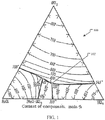
- FIG. 1 illustrates a ternary phase diagram calculated for UCl 3 -UCl 4 -NaCl fuel salts.
- the diagram 100 shows the expected melting temperature for any mixture of UCl 3 -UCl 4 -NaCl.
- the eutectic point 102 has a melt temperature of 338 °C and a composition of 17 mol % UCl 3 , 40.5 mol % UCl 4 and 42.5 mol % NaCl (except where specifically stated otherwise, all % values for chemical compounds will be in molar %), which may also be written as 17UCl 3 -40.5UCl 4 -42.5NaCl.
- the ternary diagram 100 allows the melting point temperature for any specific UCl 3 -UCl 4 -NaCl fuel salt embodiment to be identified. Likewise, UCl 3 -UCl 4 -NaCl fuel salt compositions having a specific range of melting points can be easily identified. For example, ternary salts with melting points from 300-550 °C, 338-500 °C, and 338-450 °C may be easily identified.
- FIG. 2 illustrates a method of electro-synthesis of UCl 3 from UCl 4 .
- Embodiments of the method 200 are capable of synthesizing pure UCl 3 as well as any desired binary salt of UCl 3 and another chloride salt.
- an embodiment of the method 200 can produce any ternary salt of UCl 3 , UCl 4 , and a non-fissile chloride compounds, such as NaCl.
- an embodiment of the method may be used to synthesize any UCl 3 -UCl 4 -NaCl fuel salt composition from UCl 4 -NaCl.
- the method 200 starts with an identification of the desired UCl 3 fuel salt composition to be made, illustrated by the product identification operation 202.
- the desired product may be any chloride salt of UCl 3 including pure UCl 3 , a binary salt of UCl 3 and another chloride salt, or a ternary salt of UCl 3 , UCl 4 , and a non-fissile chloride salt.
- the initial UCl 4 salt composition that is necessary can be determined, as shown in the initial salt determination operation 204.
- an initial salt of pure UCl 4 may be used as the initial salt composition.
- an initial salt of 50 mol % UCl 4 and 50 mol % NaCl may be selected.
- the initial salt is then provided in operation 206. This is illustrated by the initial salt preparation operation 206.
- the initial salt may be prepared, purchased, or otherwise obtained in the operation 206.
- the initial salt may be blended from pure UCl 4 and non-fissile chloride salt to obtain the initial salt composition.
- the initial salt is then melted and placed in an electrolysis chamber in a melting operation 208.
- the initial salt may be melted inside the chamber or melted outside of the electrolysis chamber and then moved into the chamber.
- the electrolysis chamber is a heated vessel into which the constituents of the initial salt, in solid or liquid form, are placed. The vessel is then heated to a temperature sufficient to fully melt the initial salt. The contents of the vessel may be mixed during the melting to ensure the initial salt is homogenous.
- the initial salt preparation operation 206 and the melting operation 208 may be combined by independently placing the individual solid constituents (e.g., amounts of UCl 4 and one or more non-fissile chloride salts) in the electrolysis chamber and then heating the chamber sufficiently to melt all the constituents, thus forming the initial salt in electrolysis chamber.
- the individual solid constituents e.g., amounts of UCl 4 and one or more non-fissile chloride salts
- the method 200 then applies an electric current to the initial salt in a current application operation 210.
- two or more electrodes are provided in the electrolysis chamber that are in contact with the molten initial salt.
- the current application operation 210 at least one electrode is operated as an anode and at least one other electrode is operated as the cathode.
- An electric potential is generated between the anode(s) and cathode(s) and current is applied to the initial salt.
- the electric potential is selected so that the application of current causes the reduction of UCl 4 in the initial salt to UCl 3 . That is, the electrons provided by the applied current stoichiometrically reduce the uranium U 4+ ions in UCl 4 to U 3+ ions. This, in turn, causes the UCl 4 molecules to release a Cl - ion and become UCl 3 . In this way, the application of current results in the reduction of UCl 4 to UCl 3 .
- the melting points of different salt compositions may vary significantly and, without agitation, a localized non-uniformity may result in solids forming within the chamber.
- the fuel salt is agitated during the current application operation 210.
- the agitation may be provided using any suitable means such as providing an impeller in the electrolysis chamber, vibrating the chamber itself, sparging inert gas through the molten salt, or vibrating one or more electrodes.
- the electric potential used for the electrolysis of UCl 4 is selected to preferentially reduce the UCl 4 to UCl 3 without reducing the other non-fissile chloride compound, if any, in the initial salt at the temperature and pressure at which the electrolysis chamber is operated.
- the electric potential may be calculated based on the well-known Nernst equation.
- the Nernst equation relates an electrochemical cell potential to the activities of the electroactive compounds in an electrochemical cell.
- the Nernst equation can be used to estimate the electric potential necessary to reduce the UCl 4 to UCl 3 in the initial salt at the temperature and pressure conditions of the electrolysis chamber without reducing the other non-fissile chloride compounds that may be present.
- the electric potential may be empirically determined. For example, often the actual voltage needed for electrolysis exceeds the thermodynamical value calculated by the Nernst equation. The additional voltage is referred to as overpotential. In addition, applying an overpotential may increase the rate of reaction and be desired for that effect as well.
- One method for empirically determining the electric potential to be used for a particular initial salt composition is to use a potentiostat set up to use three electrodes.
- a potentiostat is a device that typically uses five electrical connections (to a working electrode, counter electrode, reference electrode, sense, and ground) that can be used to investigate the electrochemistry of an electrochemical cell. In the three electrode setup, the ground is left unattached and grounds the electrical connections and the sense is attached to the working electrode.
- This setup uses the three electrodes to control the voltage difference across electrodes within the cell and then measures the current flow between two of three electrodes.
- the electric potential between the working electrode and the reference electrode is controlled and the resulting current flow between the working electrode and the counter electrode is measured during which the reduction reaction and its products may be observed.
- a suitable electric potential for a given reduction reaction based on the operating parameters (e.g., temperature and pressure), initial salt composition, and final salt composition may be determined.
- This electric potential then, may be used in larger electrolysis chambers having just anodes and cathodes.
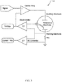
- FIG. 3 illustrates a potentiostat circuit that may be used to determine the electric potential that preferentially reduces UCl 4 to UCl 3 without reducing the other non-fissile chloride compounds that may be present.
- a current-to-voltage (I/E) converter is provided to measure the cell current.
- a control amplifier is used to drive current into the cell and also control and maintain the electric potential at the set voltage value using negative feedback.
- the input signal current is a computer-controlled voltage source, such as the output of a digital-to-analog converter. Via the computer control, the signal may be ramped through any number of voltages and the resulting current and reduction reaction observed for each. In this way, a particularly suitable electric potential for any set of operating parameters, initial salt composition, and final salt composition may be easily determined.
- FIGS. 4A and 4B illustrate an embodiment of an electrochemical cell that may be used with a potentiostat to determine a suitable electric potential for a set of operating parameters, initial salt composition, and final salt composition.
- the cell 402 is placed in a vertical melting furnace 404 that acts as a heating element. Heat from the furnace 404 maintains the salt in the cell in a molten state during the reduction reaction. The heat from the furnace 404 may be controlled, e.g., increased or decreased, over time to account for the change in melting temperature of the salt as the reduction reaction proceeds and the relative amounts of UCl 3 and UCl 4 in the salt change.
- FIG. 4B A larger view of the cell 402 showing more detail is provided in FIG. 4B .
- the cell 402 is illustrated as a vessel 408 (e.g., a quartz tube) with a stopper 406 that defines an interior region that acts as a closed electrolysis chamber.
- the stopper 406 is penetrated by each of the working electrode 410, counter electrode 412, and reference electrode 414 of the potentiostat.
- These electrodes may take the form of rods made of glassy carbon, an alloy of tungsten, or an alloy of molybdenum. Other electrode materials may also be used.
- an electrode may be made of any material that is unreactive with UCl 4 and UCl 3 at temperatures from 350 - 900 °C and pressures between 51 and 1013 kPa (0.5 and 10 atm).
- the vessel 408 and stopper 406 may be made of any material that is unreactive with UCl 4 and UCl 3 under the same conditions.
- one or more of quartz, glassy carbon, an alloy of tungsten, or an alloy of molybdenum may be used.
- a quartz vessel and stopper are used, along with a working electrode of molybdenum or tungsten, a counter electrode of glassy carbon or tungsten, and a reference electrode of silver are used.
- Molten UCl 4 salt 416 is placed in the bottom of the cell 402 and maintained in a molten state during the determination of the desired electric potential.
- chlorine gas will be collected in the headspace above the molten salt.
- the headspace may be filled with an inert gas, such as argon or nitrogen.
- the pressure of the cell may be controlled through the addition or removal of the inert gas to obtain data at different operating conditions.
- an optimum electric potential for a given reduction reaction based on the operating parameters (temperature and pressure), initial salt composition, and final salt composition may be determined.
- the same experiments and for determining the electric potential using the potentiostat of FIG. 3 and cell setup of FIGS. 4A and 4B may be used to determine how much UCl 3 is generated at a given current amperage level at the operating parameters for any particular salt composition.
- F Faraday's constant
- the total amount of UCl 3 created can be controlled by controlling the time that a current is applied.
- the conversion, as a function of current amperage and time, may be verified using the potentiostat of FIG. 3 and cell setup of FIGS. 4A and 4B and empirically determined.
- the electric potential is generated between the anode(s) and cathode(s) and current is applied to the initial salt in the current application operation 210 at an amperage and for the time necessary to obtain the desired final UCl 3 salt product.
- the electric potential is selected so that it does not cause reduction of any other chloride species, MCl n , in the initial salt, for each charge delivered to the salt by the applied current, a U 4+ ion is converted to a U 3+ ion, thereby converting a UCl 4 molecule into a UCl 3 molecule and releasing a Cl - ion into the salt.
- the amount of UCl 3 generated can be controlled, which in turn controls the final product of the method 200.
- the method 200 allows any amount of the UCl 4 in the initial salt to be converted into UCl 3 , simply by selecting the appropriate current application time, amperage and electric potential.
- the method 200 can be used to generate a quantity of pure UCl 3 , simply by providing pure UCl 4 as the initial salt and converting all the UCl 4 to UCl 3 by applying current for the appropriate amount of time.
- any UCl 3 -UCl 4 salt combination may also be obtained.
- the current application operation 210 may be performed for the length of time necessary to obtain 10UCl 3 -90UCl 4 , 25UCl 3 -75UCl 4 , 50UCl 3 -50UCl 4 , 75UCl 3 -25UCl 4 , or any other combination.
- the necessary length of time to obtain a particular conversion can be easily determined using stoichiometry.
- any desired ternary UCl 3 -UCl 4 -MCl n salt may be obtained.
- the ternary embodiment 17UCl 3 -40.5UCl 4 -42.5NaCl described in the prior applications may be obtained by using 57.5UCl 4 -42.5NaCl as the initial salt and applying current for the time necessary to convert 17 moles of the UCl 4 to UCl 3 .
- the amperage may be constant throughout the application time. In an alternative embodiment, the amperage may be varied within a range. In either embodiment, the length of time current is applied will take into account the amount of charge delivered to the salt in order to obtain the desired final product.
- the fuel salt produced by the method 200 is then available to be used in a nuclear reactor to generate power, illustrated by the generate power operation 212. This will involve removing the synthesized salt from the electrolysis chamber, moving it to a reactor core of the nuclear reactor, and operating the reactor to controllably generate heat from the fuel salt and use that heat to generate power. Depending on the embodiment, the method 200 may be performed at the site of the nuclear reactor so that fuel salt may be manufactured on demand.
- FIG. 5 illustrates an embodiment of a fuel salt electrolysis system that could be used for the synthesis method described above.
- a vessel 502 having an interior wall defining an electrolysis chamber 504 is provided.
- the vessel 502 is capable of holding molten UCl 3 and UCl 4 under the conditions of operation, such as temperatures from 350 - 900 °C and pressures from 51 and 1013 kPa (0.5 - 10 atm).
- the vessel 502 may be unitary and made of a material suitable for the salt and conditions of operation, that is resistant to corrosion and/or radiation degradation due to the fuel salt.
- a vessel 502 made of a material unreactive with UCl 4 and UCl 3 at temperatures from 350 - 900 °C and pressures from 0.5 - 10 atm would be suitable.
- a liner or protective layer may be provided on the salt-facing interior wall of the vessel 502.
- the protective layer is made of a material unreactive with UCl 4 and UCl 3 at temperatures from 350 - 900 °C and pressures from 0.5 - 10 atm.
- the protective layer may or may not be a structural element and may only be provided to protect the material of vessel 502 from degradation by the salt.
- the vessel 502 or protective layer material that is salt-facing may be quartz, glassy carbon, an alloy of tungsten, or an alloy of molybdenum.
- Other corrosion resistant materials are also possible and include any material known in the art suitable for providing an internal surface of a reactor with corrosion and/or radiation resistance to a corresponding nuclear fuel salt.
- the material may vary depending on the salt composition used, particularly on the cation M of the non-fissionable salt MCl n .
- the vessel 502 and/or a protective layer may include one or more refractory metals.
- the vessel 502 and/or a protective layer may include, but is not limited to, one or more of molybdenum, tantalum, niobium, tungsten or rhenium.
- the protective layer 128 includes one or more refractory alloys.
- the protective layer 128 may include, but is not limited to, one or more of a molybdenum alloy (e.g., titanium-zirconium-molybdenum (TZM) alloy), a tungsten alloy, tantalum, or a rhenium.
- the vessel 502 and/or a protective layer includes one or more nickel alloys.
- the vessel 502 and/or a protective layer includes a carbide, such as, but not limited to, silicon carbide.
- the electrolysis chamber 504 is the interior of the vessel 502. It may be completely filled with salt 506 or partially filled (as shown) so that there is a headspace 508 of gas above the salt level 510.
- the vessel is provided a vessel head 530 as a cover that creates a closed chamber 504.
- the vessel 502 has no penetrations, with every access point being through the head 530. This adds a measure of safety to the handling of the fuel salt.
- An additional safety measure, not shown, is to provide a secondary containment shell around the vessel 502. In the event of a leak, the secondary containment shell will prevent any fuel salt from being released.
- One or more sealable access ports are provided in the head 530 to allow salt to be placed into and removed from the electrolysis chamber 504.
- Other penetrations in the head 530 include penetrations for wiring, gas removal, pressurization, and the impeller rod 522, which will be discussed in greater detail below.
- Conditions in the electrolysis chamber 504 may be monitored by one or more monitoring devices 540, such as the temperature monitor 540 shown. Monitoring devices may be located in any location or component, as necessary. For example, a pressure monitor may be located in the vessel head 530 or in the headspace 508. Temperature monitors 540 may be located in the chamber 504 below the salt level 510, in the vessel 502 or in the head 530. Temperature and pressure monitors 540 may also be located in the gas collection system and used to monitor the conditions of gas leaving the system 500.
- two electrodes 512, 514 are provided.
- One electrode 512 operates as an anode 512.
- the other operates as a cathode 514.
- multiple cathodes 514 and/or anodes 512 may be provided.
- different anode 512 and cathode 514 configurations may be used.
- the anode 512 may be a single electrode centrally-located within the electrolysis chamber 504 and the cathode 514 may take the form of a ring around the centrally-located cathode, or even a sphere.
- the ring-shaped cathode 514 may be a single cathode, or may be multiple spaced-apart electrodes that generally form a ring with the anode 512 at the center.
- the electrodes 512, 514 may be of the same or different material.
- the material is unreactive with UCl 4 and UCl 3 at the operating conditions, such as temperatures from 350 - 900 °C and pressures from 51 and 1013 kPa (0.5-10 atm).
- suitable materials include silver, glassy carbon, an alloy of tungsten, or an alloy of molybdenum. Other materials are also possible.
- a direct current power source 516 is connected to the cathode 514 and anode 512.
- the power source 516 is capable of creating a potential and applying electric current between the cathode 514 and anode 512.
- an ammeter 518 is also provided to monitor the applied current.
- An impeller 520 connected by a rod 522 to a motor 524 is provided in order to agitate the salt 506.
- the salt-facing surfaces and components may be made of a corrosion and radiation damage resistant material as described above.
- the motor 524 is located out of the electrolysis chamber to protect it from the fuel salt. In an alternative embodiment, discussed above, a different system for agitating the fuel salt while in the chamber 504 may be used.
- a gas collector 532 is provided to collect Cl 2 gas produced during the synthesis of UCl 3 .
- the collector 532 is essentially a hood-like element in the electrolysis chamber 504 that directs gas bubbles 534 into a chute 536 that exits the head 530.
- the gas collector 532 is located above the anode 512, which is where the reduction reaction occurs and Cl 2 will be generated.
- no gas collector 532 is used. Rather, the Cl 2 is allowed to collect in the headspace 508 and, using a pressure relief valve, when the pressure increases to some threshold, the Cl 2 gas is removed through the head 530.
- the Cl 2 gas may be collected and reused or sold, particularly if enriched 37 Cl 2 is being used.
- a condenser 538 is provided to condense any UCl 4 which may be volatilized from the fuel salt.
- the condenser 538 illustrated is a cooling jacket surround a length of the chute 536 that cools the exiting gas to a temperature below the melting point of UCl 4 .
- Any UCl 4 gas condenses onto the sides of the chute and flows back into the electrolysis chamber 504.
- Many other condenser designs may be utilized, including designs that do not return the UCl 4 to the electrolysis chamber 504. If a non-returning design is used, the anticipated amount of UCl 4 lost with the exhaust gas may need to be accounted for when determining the initial and final salt compositions.
- a system controller 542 is also provided.
- the controller 542 is connected to the power source 516 to control the potential and electric current generated and applied to the electrodes.
- the system controller 542 is configured to maintain the potential between the cathode 514 and anode 512 within a range that reduces U 4+ to U 3+ without reducing U 3+ and, if a non-fissile salt MCl n is present, without reducing cations, M n+ , of any non-fissile salt.
- the system controller 542 may be a general purpose computer programmed to operate the system 500 or may be a purpose-built controller. In the embodiment shown, the controller 542 is attached to the monitoring devices 540, the motor 424, and the ammeter 518 through which it can control the operation of the system 500.
- the system 500 further includes a number of heating elements, illustrated as heaters 544 on the exterior walls and bottom of the vessel 502.
- the heaters are jacket heaters that run heated fluid through the heaters.
- Other heating systems may be used including placing heating elements within the electrolysis chamber 504 in contact with the salt.
- the heating elements 544 are connected to the system controller 542 so that the controller can maintain the temperature of the salt in the electrolysis chamber at the desired temperature or within the desired temperature range.
- Uranium enrichment can be easily achieved by starting with 235 U enriched UCl 4 .
- Chlorine enrichment can be obtained by providing 37 Cl enriched UCl 4 , MCl n , or both at the stoichiometric amount desired.
- gas sparging with an inert gas may be used to provide agitation within the electrolysis chamber.
- any UCl 4 gas collected with the Cl 2 exiting the vessel may be routed back into the salt via the inert gas being delivered to the sparging system.
Landscapes
- Chemical & Material Sciences (AREA)
- Organic Chemistry (AREA)
- Engineering & Computer Science (AREA)
- Chemical Kinetics & Catalysis (AREA)
- Electrochemistry (AREA)
- Materials Engineering (AREA)
- Metallurgy (AREA)
- Inorganic Chemistry (AREA)
- Physics & Mathematics (AREA)
- Life Sciences & Earth Sciences (AREA)
- Geology (AREA)
- General Life Sciences & Earth Sciences (AREA)
- Plasma & Fusion (AREA)
- General Engineering & Computer Science (AREA)
- High Energy & Nuclear Physics (AREA)
- Health & Medical Sciences (AREA)
- General Health & Medical Sciences (AREA)
- Toxicology (AREA)
- Electrolytic Production Of Metals (AREA)
Description
- The present application claims the benefit of
U.S. Provisional Patent Application No. 62/373,187 - The utilization of molten fuels in a nuclear reactor to produce power provides significant advantages as compared to solid fuels. For instance, molten fuel reactors generally provide higher power densities compared to solid fuel reactors, while at the same time having reduced fuel costs due to the relatively high cost of solid fuel fabrication.
- Binary, ternary, and quaternary chloride fuel salts of uranium, as well as other fissionable elements, have been described in co-assigned
U.S. Patent Application Serial No. 14/981,512 , titled MOLTEN NUCLEAR FUEL SALTS AND RELATED SYSTEMS AND METHODS, andU.S. Provisional Patent Application Serial No. 62/330,695 - S. A. KUZNETSOV ET AL: "Electrochemical Behavior and Some Thermodynamic Properties of UCl4 and UCl3 Dissolved in a LiCl-KCl Eutectic Melt", JOURNAL OF THE ELECTROCHEMICAL SOCIETY, vol. 152, no. 4, 1 January 2005 (2005-01-01), page C203, ISSN: 0013-4651, DOI: 10.1149/1.1864532 discloses synthesising UCl3 from UCl4 dissolved in a LiCl-KCl eutectic melt by applying a current to the melt.
- Binary and ternary fuel salts that include both UCl3 and UCl4 are typically made by separately manufacturing the UCl3 and UCl4 and then mixing them in the appropriate amounts to obtain the final salt composition. There are two main approaches to UCl3 synthesis. The first one reacts uranium metal with hydrogen gas to form uranium trihydride. The uranium trihydride then reacts with injected hydrochloric acid gas to form the UCl3. This reaction requires uranium metal as a reactant which is both expensive and a different uranium compound than what is required to make the UCl4. The second UCl3 synthesis method reacts UCl4 with hydrogen gas at high temperatures (540-580 °C) to directly form UCl3 and hydrochloric acid gas. The problem with this second route is that UCl4 begins to melt close to the operating temperature of the reaction and forms a liquid cap which prevents further reaction with hydrogen gas. The result is very slow reaction kinetics.
- Particular and preferred aspects of the present invention are set out in the appended claims. Where the aforementioned applications describe a wide range of binary and ternary chloride fuel salts of uranium, as well as other related salts and technologies, this disclosure describes systems and methods for synthesizing UCl3 from UCl4. These systems and methods may also be used to directly synthesize binary and ternary embodiments of uranium salts of chloride usable as nuclear fuel in certain molten salt reactor designs. The systems and methods described herein are capable of synthesizing any desired uranium chloride fuel salt that is a combination of UCl4, UCl3 and one or more non-fissile chloride compounds, such as NaCl. In particular, the systems and methods described herein are capable of synthesizing any UCl3-UCl4-NaCl or UCl3-NaCl fuel salt composition from UCl4-NaCl.
- These and various other features as well as advantages which characterize the systems and methods described herein will be apparent from a reading of the following detailed description and a review of the associated drawings. Additional features are set forth in the description which follows, and in part will be apparent from the description, or may be learned by practice of the technology. The benefits and features of the technology will be realized and attained by the structure particularly pointed out in the written description and claims hereof as well as the appended drawings.
- It is to be understood that both the foregoing general description and the following detailed description are exemplary and explanatory and are intended to provide further explanation of the invention as claimed.
- The following drawing figures, which form a part of this application, are illustrative of described technology and are not meant to limit the scope of the invention as claimed in any manner, which scope shall be based on the claims appended hereto.
-
FIG. 1 illustrates a ternary phase diagram calculated for UCl3-UCl4-NaCl fuel salts. -
FIG. 2 illustrates a method of electro-synthesis of UCl3 from UCl4. -
FIG. 3 illustrates a potentiostat circuit that may be used to determine the electric potential that preferentially reduces UCl4 to UCl3 without reducing the other non-fissile chloride compounds that may be present. -
FIGS. 4A and 4B illustrate an embodiment of an electrochemical cell that may be used with a potentiostat to determine a suitable electric potential for a set of operating parameters, initial salt composition, and final salt composition. -
FIG. 5 illustrates an embodiment of a fuel salt electrolysis system that could be used for the synthesis method. - Embodiments of uranium salts suitable for use as nuclear fuel include salts that are a mixture of UCl3 with one or both of UCl4 and a non-fissile chloride salt. Thus, these fuel salts include 100 % UCl3 fuel salt, as well as fuel salts that are mixtures of UCl3 and UCl4 with or without an additional non-fissile chloride salt designated by MCln. Examples of additional, non-fissile metal chlorides include NaCl, MgCl2, CaCl2, BaCl2, KCl, SrCl2, VCl3, CrCl3, TiCl4, ZrCl4, ThCl4, AcCl3, NpCl4, AmCl3, LaCl3, CeCl3, PrCl3 and/or NdCl3.
-
FIG. 1 illustrates a ternary phase diagram calculated for UCl3-UCl4-NaCl fuel salts. The diagram 100 shows the expected melting temperature for any mixture of UCl3-UCl4-NaCl. Theeutectic point 102 has a melt temperature of 338 °C and a composition of 17 mol % UCl3, 40.5 mol % UCl4 and 42.5 mol % NaCl (except where specifically stated otherwise, all % values for chemical compounds will be in molar %), which may also be written as 17UCl3-40.5UCl4-42.5NaCl. The ternary diagram 100 allows the melting point temperature for any specific UCl3-UCl4-NaCl fuel salt embodiment to be identified. Likewise, UCl3-UCl4-NaCl fuel salt compositions having a specific range of melting points can be easily identified. For example, ternary salts with melting points from 300-550 °C, 338-500 °C, and 338-450 °C may be easily identified. -
FIG. 2 illustrates a method of electro-synthesis of UCl3 from UCl4. Embodiments of themethod 200 are capable of synthesizing pure UCl3 as well as any desired binary salt of UCl3 and another chloride salt. In addition, an embodiment of themethod 200 can produce any ternary salt of UCl3, UCl4, and a non-fissile chloride compounds, such as NaCl. In particular, an embodiment of the method may be used to synthesize any UCl3-UCl4-NaCl fuel salt composition from UCl4-NaCl. - In the embodiment of the method shown, the
method 200 starts with an identification of the desired UCl3 fuel salt composition to be made, illustrated by theproduct identification operation 202. The desired product may be any chloride salt of UCl3 including pure UCl3, a binary salt of UCl3 and another chloride salt, or a ternary salt of UCl3, UCl4, and a non-fissile chloride salt. - From the composition of the desired final product, the initial UCl4 salt composition that is necessary can be determined, as shown in the initial
salt determination operation 204. For example, if pure UCl3 is the desired product, an initial salt of pure UCl4 may be used as the initial salt composition. As another example, if a final salt of 50 mol % UCl3 and 50 mol % NaCl is desired, an initial salt of 50 mol % UCl4 and 50 mol % NaCl may be selected. - In the electro-
synthesis method 200, the initial salt is then provided inoperation 206. This is illustrated by the initialsalt preparation operation 206. The initial salt may be prepared, purchased, or otherwise obtained in theoperation 206. For example, in an embodiment, the initial salt may be blended from pure UCl4 and non-fissile chloride salt to obtain the initial salt composition. - In the embodiment of the
method 200 illustrated, the initial salt is then melted and placed in an electrolysis chamber in amelting operation 208. Depending on the embodiment, the initial salt may be melted inside the chamber or melted outside of the electrolysis chamber and then moved into the chamber. For example, in an embodiment, the electrolysis chamber is a heated vessel into which the constituents of the initial salt, in solid or liquid form, are placed. The vessel is then heated to a temperature sufficient to fully melt the initial salt. The contents of the vessel may be mixed during the melting to ensure the initial salt is homogenous. - In yet another embodiment, the initial
salt preparation operation 206 and themelting operation 208 may be combined by independently placing the individual solid constituents (e.g., amounts of UCl4 and one or more non-fissile chloride salts) in the electrolysis chamber and then heating the chamber sufficiently to melt all the constituents, thus forming the initial salt in electrolysis chamber. - The
method 200 then applies an electric current to the initial salt in acurrent application operation 210. To apply the current, two or more electrodes are provided in the electrolysis chamber that are in contact with the molten initial salt. In thecurrent application operation 210, at least one electrode is operated as an anode and at least one other electrode is operated as the cathode. An electric potential is generated between the anode(s) and cathode(s) and current is applied to the initial salt. The electric potential is selected so that the application of current causes the reduction of UCl4 in the initial salt to UCl3. That is, the electrons provided by the applied current stoichiometrically reduce the uranium U4+ ions in UCl4 to U3+ ions. This, in turn, causes the UCl4 molecules to release a Cl- ion and become UCl3. In this way, the application of current results in the reduction of UCl4 to UCl3. - As illustrated in
FIG. 1 , the melting points of different salt compositions may vary significantly and, without agitation, a localized non-uniformity may result in solids forming within the chamber. In order to prevent kinetic effects near the electrodes or non-uniformities within the electrolysis chamber the fuel salt is agitated during thecurrent application operation 210. The agitation may be provided using any suitable means such as providing an impeller in the electrolysis chamber, vibrating the chamber itself, sparging inert gas through the molten salt, or vibrating one or more electrodes. - In an embodiment, the electric potential used for the electrolysis of UCl4 is selected to preferentially reduce the UCl4 to UCl3 without reducing the other non-fissile chloride compound, if any, in the initial salt at the temperature and pressure at which the electrolysis chamber is operated. The electric potential may be calculated based on the well-known Nernst equation. The Nernst equation relates an electrochemical cell potential to the activities of the electroactive compounds in an electrochemical cell. The Nernst equation can be used to estimate the electric potential necessary to reduce the UCl4 to UCl3 in the initial salt at the temperature and pressure conditions of the electrolysis chamber without reducing the other non-fissile chloride compounds that may be present.
- Alternatively, the electric potential may be empirically determined. For example, often the actual voltage needed for electrolysis exceeds the thermodynamical value calculated by the Nernst equation. The additional voltage is referred to as overpotential. In addition, applying an overpotential may increase the rate of reaction and be desired for that effect as well. One method for empirically determining the electric potential to be used for a particular initial salt composition is to use a potentiostat set up to use three electrodes. A potentiostat is a device that typically uses five electrical connections (to a working electrode, counter electrode, reference electrode, sense, and ground) that can be used to investigate the electrochemistry of an electrochemical cell. In the three electrode setup, the ground is left unattached and grounds the electrical connections and the sense is attached to the working electrode. This setup, then, uses the three electrodes to control the voltage difference across electrodes within the cell and then measures the current flow between two of three electrodes. The electric potential between the working electrode and the reference electrode is controlled and the resulting current flow between the working electrode and the counter electrode is measured during which the reduction reaction and its products may be observed. By changing the electric potential to different values, a suitable electric potential for a given reduction reaction based on the operating parameters (e.g., temperature and pressure), initial salt composition, and final salt composition may be determined. This electric potential, then, may be used in larger electrolysis chambers having just anodes and cathodes.
-
FIG. 3 illustrates a potentiostat circuit that may be used to determine the electric potential that preferentially reduces UCl4 to UCl3 without reducing the other non-fissile chloride compounds that may be present. In thepotentiostat 300 shown, a current-to-voltage (I/E) converter is provided to measure the cell current. A control amplifier is used to drive current into the cell and also control and maintain the electric potential at the set voltage value using negative feedback. The input signal current is a computer-controlled voltage source, such as the output of a digital-to-analog converter. Via the computer control, the signal may be ramped through any number of voltages and the resulting current and reduction reaction observed for each. In this way, a particularly suitable electric potential for any set of operating parameters, initial salt composition, and final salt composition may be easily determined. -
FIGS. 4A and 4B illustrate an embodiment of an electrochemical cell that may be used with a potentiostat to determine a suitable electric potential for a set of operating parameters, initial salt composition, and final salt composition. In thecell setup 400 shown inFIG. 4A , thecell 402 is placed in avertical melting furnace 404 that acts as a heating element. Heat from thefurnace 404 maintains the salt in the cell in a molten state during the reduction reaction. The heat from thefurnace 404 may be controlled, e.g., increased or decreased, over time to account for the change in melting temperature of the salt as the reduction reaction proceeds and the relative amounts of UCl3 and UCl4 in the salt change. - A larger view of the
cell 402 showing more detail is provided inFIG. 4B . Thecell 402 is illustrated as a vessel 408 (e.g., a quartz tube) with astopper 406 that defines an interior region that acts as a closed electrolysis chamber. Thestopper 406 is penetrated by each of the workingelectrode 410,counter electrode 412, andreference electrode 414 of the potentiostat. These electrodes may take the form of rods made of glassy carbon, an alloy of tungsten, or an alloy of molybdenum. Other electrode materials may also be used. For example, in an embodiment, an electrode may be made of any material that is unreactive with UCl4 and UCl3 at temperatures from 350 - 900 °C and pressures between 51 and 1013 kPa (0.5 and 10 atm). Likewise, thevessel 408 andstopper 406 may be made of any material that is unreactive with UCl4 and UCl3 under the same conditions. For example, one or more of quartz, glassy carbon, an alloy of tungsten, or an alloy of molybdenum may be used. In the embodiment shown, a quartz vessel and stopper are used, along with a working electrode of molybdenum or tungsten, a counter electrode of glassy carbon or tungsten, and a reference electrode of silver are used. - Molten UCl4 salt 416 is placed in the bottom of the
cell 402 and maintained in a molten state during the determination of the desired electric potential. In the embodiment shown, chlorine gas will be collected in the headspace above the molten salt. The headspace may be filled with an inert gas, such as argon or nitrogen. The pressure of the cell may be controlled through the addition or removal of the inert gas to obtain data at different operating conditions. Using the potentiostat ofFIG. 3 and cell setup ofFIGS. 4A and 4B , an optimum electric potential for a given reduction reaction based on the operating parameters (temperature and pressure), initial salt composition, and final salt composition may be determined. - In addition, the same experiments and for determining the electric potential using the potentiostat of
FIG. 3 and cell setup ofFIGS. 4A and 4B may be used to determine how much UCl3 is generated at a given current amperage level at the operating parameters for any particular salt composition. The integral of the applied current with respect to time gives total charge transferred to the salt, which can then be related to moles of uranium atoms reduced through Faraday's constant (F=96485 C/mol e-) as long as the current efficiency is known or estimated. Thus, the total amount of UCl3 created can be controlled by controlling the time that a current is applied. The conversion, as a function of current amperage and time, may be verified using the potentiostat ofFIG. 3 and cell setup ofFIGS. 4A and 4B and empirically determined. - Returning now to the method of
FIG. 2 , the electric potential, however it was determined, is generated between the anode(s) and cathode(s) and current is applied to the initial salt in thecurrent application operation 210 at an amperage and for the time necessary to obtain the desired final UCl3 salt product. As described above, since the electric potential is selected so that it does not cause reduction of any other chloride species, MCln, in the initial salt, for each charge delivered to the salt by the applied current, a U4+ ion is converted to a U3+ ion, thereby converting a UCl4 molecule into a UCl3 molecule and releasing a Cl- ion into the salt. Thus, by controlling the amperage and time over which the current is applied, the amount of UCl3 generated can be controlled, which in turn controls the final product of themethod 200. - The
method 200 allows any amount of the UCl4 in the initial salt to be converted into UCl3, simply by selecting the appropriate current application time, amperage and electric potential. For example, themethod 200 can be used to generate a quantity of pure UCl3, simply by providing pure UCl4 as the initial salt and converting all the UCl4 to UCl3 by applying current for the appropriate amount of time. - Using pure (99.9 %+) UCl4 as the initial salt any UCl3-UCl4 salt combination may also be obtained. For example, for a given amount of UCl4, the
current application operation 210 may be performed for the length of time necessary to obtain 10UCl3-90UCl4, 25UCl3-75UCl4, 50UCl3-50UCl4, 75UCl3-25UCl4, or any other combination. Given the initial salt quantity, composition, and the amperage of the applied current, the necessary length of time to obtain a particular conversion can be easily determined using stoichiometry. - Similarly, by using a UCl4-MCln initial salt, any desired ternary UCl3-UCl4-MCln salt may be obtained. For example, the ternary embodiment 17UCl3-40.5UCl4-42.5NaCl described in the prior applications may be obtained by using 57.5UCl4-42.5NaCl as the initial salt and applying current for the time necessary to convert 17 moles of the UCl4 to UCl3.
- During the
current application operation 210, the amperage may be constant throughout the application time. In an alternative embodiment, the amperage may be varied within a range. In either embodiment, the length of time current is applied will take into account the amount of charge delivered to the salt in order to obtain the desired final product. - The fuel salt produced by the
method 200 is then available to be used in a nuclear reactor to generate power, illustrated by the generatepower operation 212. This will involve removing the synthesized salt from the electrolysis chamber, moving it to a reactor core of the nuclear reactor, and operating the reactor to controllably generate heat from the fuel salt and use that heat to generate power. Depending on the embodiment, themethod 200 may be performed at the site of the nuclear reactor so that fuel salt may be manufactured on demand. -
FIG. 5 illustrates an embodiment of a fuel salt electrolysis system that could be used for the synthesis method described above. In thesystem 500 shown, avessel 502 having an interior wall defining anelectrolysis chamber 504 is provided. Thevessel 502 is capable of holding molten UCl3 and UCl4 under the conditions of operation, such as temperatures from 350 - 900 °C and pressures from 51 and 1013 kPa (0.5 - 10 atm). In an embodiment, thevessel 502 may be unitary and made of a material suitable for the salt and conditions of operation, that is resistant to corrosion and/or radiation degradation due to the fuel salt. Thus, avessel 502 made of a material unreactive with UCl4 and UCl3 at temperatures from 350 - 900 °C and pressures from 0.5 - 10 atm would be suitable. - In an alternative embodiment, a liner or protective layer may be provided on the salt-facing interior wall of the
vessel 502. The protective layer is made of a material unreactive with UCl4 and UCl3 at temperatures from 350 - 900 °C and pressures from 0.5 - 10 atm. In this embodiment, the protective layer may or may not be a structural element and may only be provided to protect the material ofvessel 502 from degradation by the salt. - In an embodiment, the
vessel 502 or protective layer material that is salt-facing may be quartz, glassy carbon, an alloy of tungsten, or an alloy of molybdenum. Other corrosion resistant materials are also possible and include any material known in the art suitable for providing an internal surface of a reactor with corrosion and/or radiation resistance to a corresponding nuclear fuel salt. Thus, the material may vary depending on the salt composition used, particularly on the cation M of the non-fissionable salt MCln. In one embodiment, thevessel 502 and/or a protective layer may include one or more refractory metals. For example, thevessel 502 and/or a protective layer may include, but is not limited to, one or more of molybdenum, tantalum, niobium, tungsten or rhenium. In another embodiment, the protective layer 128 includes one or more refractory alloys. For example, the protective layer 128 may include, but is not limited to, one or more of a molybdenum alloy (e.g., titanium-zirconium-molybdenum (TZM) alloy), a tungsten alloy, tantalum, or a rhenium. In another embodiment, thevessel 502 and/or a protective layer includes one or more nickel alloys. In another embodiment, thevessel 502 and/or a protective layer includes a carbide, such as, but not limited to, silicon carbide. - The
electrolysis chamber 504 is the interior of thevessel 502. It may be completely filled withsalt 506 or partially filled (as shown) so that there is aheadspace 508 of gas above thesalt level 510. - In the embodiment shown, the vessel is provided a
vessel head 530 as a cover that creates aclosed chamber 504. In the embodiment shown, thevessel 502 has no penetrations, with every access point being through thehead 530. This adds a measure of safety to the handling of the fuel salt. An additional safety measure, not shown, is to provide a secondary containment shell around thevessel 502. In the event of a leak, the secondary containment shell will prevent any fuel salt from being released. - One or more sealable access ports, such as the
port 528 illustrated, are provided in thehead 530 to allow salt to be placed into and removed from theelectrolysis chamber 504. Other penetrations in thehead 530 include penetrations for wiring, gas removal, pressurization, and theimpeller rod 522, which will be discussed in greater detail below. - Conditions in the
electrolysis chamber 504 may be monitored by one ormore monitoring devices 540, such as the temperature monitor 540 shown. Monitoring devices may be located in any location or component, as necessary. For example, a pressure monitor may be located in thevessel head 530 or in theheadspace 508. Temperature monitors 540 may be located in thechamber 504 below thesalt level 510, in thevessel 502 or in thehead 530. Temperature and pressure monitors 540 may also be located in the gas collection system and used to monitor the conditions of gas leaving thesystem 500. - In the embodiment shown, two
electrodes electrode 512 operates as ananode 512. The other operates as acathode 514. In alternative embodiments,multiple cathodes 514 and/oranodes 512 may be provided. In addition,different anode 512 andcathode 514 configurations may be used. For example, in an embodiment theanode 512 may be a single electrode centrally-located within theelectrolysis chamber 504 and thecathode 514 may take the form of a ring around the centrally-located cathode, or even a sphere. The ring-shapedcathode 514 may be a single cathode, or may be multiple spaced-apart electrodes that generally form a ring with theanode 512 at the center. - The
electrodes - A direct
current power source 516 is connected to thecathode 514 andanode 512. Thepower source 516 is capable of creating a potential and applying electric current between thecathode 514 andanode 512. In the embodiment shown, anammeter 518 is also provided to monitor the applied current. - An
impeller 520 connected by arod 522 to amotor 524 is provided in order to agitate thesalt 506. Again, the salt-facing surfaces and components may be made of a corrosion and radiation damage resistant material as described above. Themotor 524 is located out of the electrolysis chamber to protect it from the fuel salt. In an alternative embodiment, discussed above, a different system for agitating the fuel salt while in thechamber 504 may be used. - A
gas collector 532 is provided to collect Cl2 gas produced during the synthesis of UCl3. In the embodiment shown, thecollector 532 is essentially a hood-like element in theelectrolysis chamber 504 that directs gas bubbles 534 into achute 536 that exits thehead 530. Thegas collector 532 is located above theanode 512, which is where the reduction reaction occurs and Cl2 will be generated. In an alternative embodiment nogas collector 532 is used. Rather, the Cl2 is allowed to collect in theheadspace 508 and, using a pressure relief valve, when the pressure increases to some threshold, the Cl2 gas is removed through thehead 530. In an embodiment, the Cl2 gas may be collected and reused or sold, particularly if enriched 37Cl2 is being used. - In the embodiment shown, a
condenser 538 is provided to condense any UCl4 which may be volatilized from the fuel salt. Thecondenser 538 illustrated is a cooling jacket surround a length of thechute 536 that cools the exiting gas to a temperature below the melting point of UCl4. Any UCl4 gas condenses onto the sides of the chute and flows back into theelectrolysis chamber 504. Many other condenser designs may be utilized, including designs that do not return the UCl4 to theelectrolysis chamber 504. If a non-returning design is used, the anticipated amount of UCl4 lost with the exhaust gas may need to be accounted for when determining the initial and final salt compositions. - A
system controller 542 is also provided. Thecontroller 542 is connected to thepower source 516 to control the potential and electric current generated and applied to the electrodes. As discussed above, thesystem controller 542 is configured to maintain the potential between thecathode 514 andanode 512 within a range that reduces U4+ to U3+ without reducing U3+ and, if a non-fissile salt MCln is present, without reducing cations, Mn+, of any non-fissile salt. Thesystem controller 542 may be a general purpose computer programmed to operate thesystem 500 or may be a purpose-built controller. In the embodiment shown, thecontroller 542 is attached to themonitoring devices 540, the motor 424, and theammeter 518 through which it can control the operation of thesystem 500. - The
system 500 further includes a number of heating elements, illustrated asheaters 544 on the exterior walls and bottom of thevessel 502. In an embodiment, the heaters are jacket heaters that run heated fluid through the heaters. Other heating systems may be used including placing heating elements within theelectrolysis chamber 504 in contact with the salt. Theheating elements 544 are connected to thesystem controller 542 so that the controller can maintain the temperature of the salt in the electrolysis chamber at the desired temperature or within the desired temperature range. - Note that the synthesis method and systems described herein may be easily adapted to generate enriched-uranium or enriched-chloride fuel salts. Uranium enrichment can be easily achieved by starting with 235U enriched UCl4. Chlorine enrichment can be obtained by providing 37Cl enriched UCl4, MCln, or both at the stoichiometric amount desired.
- It will be clear that the systems and methods described herein are well adapted to attain the ends and advantages mentioned as well as those inherent therein. Those skilled in the art will recognize that the methods and systems within this specification may be implemented in many manners and as such is not to be limited by the foregoing exemplified embodiments and examples. In other words, functional elements, such as the
controller 542, being performed by a single or multiple components, in various combinations of hardware and software, and individual functions can be distributed among software applications at either the client or server level. In this regard, any number of the features of the different embodiments described herein may be combined into one single embodiment and alternate embodiments having fewer than or more than all of the features herein described are possible. - While various embodiments have been described for purposes of this disclosure, various changes and modifications may be made which are well within the scope of the technology described herein. For example, gas sparging with an inert gas may be used to provide agitation within the electrolysis chamber. Further, in such a system, any UCl4 gas collected with the Cl2 exiting the vessel may be routed back into the salt via the inert gas being delivered to the sparging system. Numerous other changes may be made which will readily suggest themselves to those skilled in the art and which are encompassed in the scope of the disclosure and as defined in the appended claims.
Claims (15)
- A method for synthesizing UCl3 comprising:
providing a quantity of fuel salt, the fuel salt having a first amount of UCl4;melting the quantity of fuel salt; andapplying an electric current to the fuel salt, thereby reducing at least some UCl4 to UCl3; andagitating the fuel salt while applying the electric current to the fuel salt. - The method of claim 1 further comprising:
applying the electric current to the fuel salt for a first length of time sufficient to reduce all of the UCl4 to UCl3. - The method of claim 1 further comprising:
applying the electric current to the fuel salt at an amperage and for a second length of time, wherein the amperage of the applied electric current over the second length of time is stoichiometrically calculated to create a target amount of UCl3. - The method of claim 3 wherein applying the electric current to the fuel salt comprises:
applying the electric current to the fuel salt at a constant amperage for the second length of time. - The method of claim 3 further comprising:identifying a desired final ratio of UCl3 to UCl4 to be obtained in the quantity of fuel salt;determining the target amount of UCl3 to be created based on the desired final ratio and the quantity of fuel salt;stoichiometrically determining the amperage and second length of time for the applied electric current based on the target amount of UCl3 to be created; andapplying the electric current at the stoichiometrically determined amperage for the second length of time, thereby creating a fuel salt having the desired final ratio of UCl3 to UCl4.
- The method of claim 3 wherein the stoichiometric amount of electric current is calculated to reduce all of the UCl4 to UCl3.
- The method of claim 1 wherein the fuel salt is at least 99.9% UCl4.
- The method of claim 1 wherein the fuel salt is a mixture of UCl4 and at least one non-fissile chloride compound.
- The method of claim 8 wherein the at least one non-fissile chloride compound is one or more of NaCl, MgCl2, CaCl2, BaCl2, KCl, SrCl2, VCl3, CrCl3, TiC14, ZrCl4, ThCl4, AcCl3, NpCl4, AmCl3, LaCl3, CeCl3, PrCl3 and/or NdCl3.
- The method of claim 8 wherein the at least one non-fissile chloride compound includes NaCl.
- The method of claim 1 wherein applying the electric current further comprises:submerging at least one anode and at least one cathode in the molten fuel salt; andpassing the electric current between the at least one anode and at least one cathode submerged in the molten fuel salt.
- The method of claim 11 further comprising:
generating an electric potential between the at least one anode and the at least one cathode. - The method of claim 12 wherein the fuel salt is a mixture of UCl4 and at least one non-fissile chloride compound and generating further comprises:
selecting the electric potential based on a temperature and pressure of the fuel salt to preferentially reduce the UCl4 to UCl3 without reducing the at least one non-fissile chloride compound - The method of claim 1 further comprising:
maintaining the fuel salt in a molten state while applying the electric current to the fuel salt wherein maintaining the fuel salt in a molten state comprises:monitoring the electric current applied to the fuel salt; andchanging one or both of the temperature or pressure of the fuel salt based on the monitored electric current. - The method of claim 1 further comprising:
collecting Cl2 generated by reducing the UCl4 in the fuel salt to UCl3, wherein collecting Cl2 comprises:containing the fuel salt in a closed vessel while applying the electric current to the fuel salt;removing gas evolved during the applying operation from the closed vessel;separating Cl2 in the removed gas from UCl4 in the removed gas, the separating comprising: condensing the UCl4 in the removed gas into liquid UCl3; andreturning the liquid UCl4 to the closed vessel.
Priority Applications (1)
| Application Number | Priority Date | Filing Date | Title |
|---|---|---|---|
| EP21187359.1A EP3922605A1 (en) | 2016-08-10 | 2017-08-09 | Electro-synthesis of uranium chloride fuel salts |
Applications Claiming Priority (2)
| Application Number | Priority Date | Filing Date | Title |
|---|---|---|---|
| US201662373187P | 2016-08-10 | 2016-08-10 | |
| PCT/US2017/046139 WO2018031681A1 (en) | 2016-08-10 | 2017-08-09 | Electro-synthesis of uranium chloride fuel salts |
Related Child Applications (2)
| Application Number | Title | Priority Date | Filing Date |
|---|---|---|---|
| EP21187359.1A Division EP3922605A1 (en) | 2016-08-10 | 2017-08-09 | Electro-synthesis of uranium chloride fuel salts |
| EP21187359.1A Division-Into EP3922605A1 (en) | 2016-08-10 | 2017-08-09 | Electro-synthesis of uranium chloride fuel salts |
Publications (2)
| Publication Number | Publication Date |
|---|---|
| EP3497062A1 EP3497062A1 (en) | 2019-06-19 |
| EP3497062B1 true EP3497062B1 (en) | 2021-09-29 |
Family
ID=60421837
Family Applications (2)
| Application Number | Title | Priority Date | Filing Date |
|---|---|---|---|
| EP17801796.8A Active EP3497062B1 (en) | 2016-08-10 | 2017-08-09 | Electro-synthesis of uranium chloride fuel salts |
| EP21187359.1A Pending EP3922605A1 (en) | 2016-08-10 | 2017-08-09 | Electro-synthesis of uranium chloride fuel salts |
Family Applications After (1)
| Application Number | Title | Priority Date | Filing Date |
|---|---|---|---|
| EP21187359.1A Pending EP3922605A1 (en) | 2016-08-10 | 2017-08-09 | Electro-synthesis of uranium chloride fuel salts |
Country Status (3)
| Country | Link |
|---|---|
| US (2) | US10566096B2 (en) |
| EP (2) | EP3497062B1 (en) |
| WO (1) | WO2018031681A1 (en) |
Families Citing this family (30)
| Publication number | Priority date | Publication date | Assignee | Title |
|---|---|---|---|---|
| JP2018507396A (en) | 2014-12-29 | 2018-03-15 | テラパワー, エルエルシー | Nuclear material processing |
| US11276503B2 (en) | 2014-12-29 | 2022-03-15 | Terrapower, Llc | Anti-proliferation safeguards for nuclear fuel salts |
| US10141079B2 (en) | 2014-12-29 | 2018-11-27 | Terrapower, Llc | Targetry coupled separations |
| EP3357068B1 (en) | 2015-09-30 | 2020-06-17 | TerraPower LLC | Nuclear fast reactor with neutron reflector assembly for dynamic spectrum shifting |
| US10867710B2 (en) | 2015-09-30 | 2020-12-15 | Terrapower, Llc | Molten fuel nuclear reactor with neutron reflecting coolant |
| US10665356B2 (en) | 2015-09-30 | 2020-05-26 | Terrapower, Llc | Molten fuel nuclear reactor with neutron reflecting coolant |
| MX391709B (en) | 2016-05-02 | 2025-03-21 | Terrapower Llc | IMPROVED CONFIGURATIONS FOR COOLING AND PUMPING OF MELTED FUEL REACTOR. |
| EP3485496B1 (en) | 2016-07-15 | 2020-04-15 | TerraPower, LLC | Vertically-segmented nuclear reactor |
| EP3497062B1 (en) | 2016-08-10 | 2021-09-29 | TerraPower, LLC | Electro-synthesis of uranium chloride fuel salts |
| US10923238B2 (en) | 2016-11-15 | 2021-02-16 | Terrapower, Llc | Direct reactor auxiliary cooling system for a molten salt nuclear reactor |
| CA3088265A1 (en) | 2018-01-31 | 2019-08-08 | Terrapower, Llc | Direct heat exchanger for molten chloride fast reactor |
| EP4297043A3 (en) | 2018-03-12 | 2024-06-12 | TerraPower LLC | Reflector assembly for a molten chloride fast reactor |
| WO2020060941A1 (en) | 2018-09-14 | 2020-03-26 | Terrapower, Llc | Corrosion-resistant coolant salt and method for making same |
| CN110144598B (en) * | 2019-06-14 | 2020-06-26 | 中国科学院高能物理研究所 | A kind of preparation method and application of uranium trichloride |
| CN110289109B (en) * | 2019-07-08 | 2020-08-28 | 西安交通大学 | Liquid chloride cooled honeycomb briquette-like fuel assembly and reactor core using same |
| US11931763B2 (en) | 2019-11-08 | 2024-03-19 | Abilene Christian University | Identifying and quantifying components in a high-melting-point liquid |
| CA3162414A1 (en) | 2019-12-23 | 2021-07-01 | Kent E. Wardle | Molten fuel reactors and orifice ring plates for molten fuel reactors |
| US11728052B2 (en) | 2020-08-17 | 2023-08-15 | Terra Power, Llc | Fast spectrum molten chloride test reactors |
| US12018779B2 (en) | 2021-09-21 | 2024-06-25 | Abilene Christian University | Stabilizing face ring joint flange and assembly thereof |
| US20230278885A1 (en) * | 2022-03-02 | 2023-09-07 | Battelle Energy Alliance, Llc | Methods of producing uranium chloride and compositions comprising uranium chloride |
| US12467831B2 (en) | 2022-11-18 | 2025-11-11 | Georgia Tech Research Corporation | Molten salt sampling system and methods of use thereof |
| US12480860B2 (en) | 2022-12-07 | 2025-11-25 | Abilene Christian University | In-situ corrosion monitoring device and methods of use thereof |
| US12562289B2 (en) | 2023-01-20 | 2026-02-24 | Abilene Christian University | Fission product trap for salt pipe and pump shaft seals and methods of use thereof |
| US12249434B2 (en) | 2023-03-31 | 2025-03-11 | Abilene Christian University | Thermal expansion support system and methods of use thereof |
| US12603187B2 (en) | 2023-07-11 | 2026-04-14 | Abilene Christian University | Fluid level control system for a molten fuel salt sampling tank in a nuclear reactor system |
| WO2025034739A2 (en) | 2023-08-07 | 2025-02-13 | Abilene Christian University | A method calibrating power monitors for molten salt reactors at low power |
| US12012827B1 (en) | 2023-09-11 | 2024-06-18 | Natura Resources LLC | Nuclear reactor integrated oil and gas production systems and methods of operation |
| US12500006B2 (en) | 2023-12-05 | 2025-12-16 | Natura Resources LLC | Deployment method and systems for molten salt reactors |
| US12596817B2 (en) | 2023-12-08 | 2026-04-07 | The Texas A&M University System | Secure remote controls package for semi-autonomous systems |
| US12347577B1 (en) | 2024-04-11 | 2025-07-01 | Natura Resources LLC | Fuel salt shipping system |
Family Cites Families (96)
| Publication number | Priority date | Publication date | Assignee | Title |
|---|---|---|---|---|
| CA631890A (en) | 1961-11-28 | Government Of The United States Of America As Represented By The Secretary Of The Navy (The) | Experimental liquid metal fuel reactor | |
| US2375009A (en) | 1940-02-07 | 1945-05-01 | Mathieson Alkali Works | Process for the purification of magnesium chloride |
| US2945794A (en) | 1952-11-18 | 1960-07-19 | Charles E Winters | Neutronic reactor operational method and core system |
| GB739968A (en) | 1953-04-06 | 1955-11-02 | Babcock & Wilcox Ltd | Improvements in tubulous vapour generators |
| US2874106A (en) | 1955-04-11 | 1959-02-17 | Hammond R Philip | Homogeneous nuclear reactor |
| CH345085A (en) | 1955-07-08 | 1960-03-15 | Gen Electric | Nuclear reactor plant |
| US2920024A (en) | 1956-07-27 | 1960-01-05 | Barton Charles Julian | Molten fluoride nuclear reactor fuel |
| NL250500A (en) | 1959-04-14 | |||
| BE591155A (en) | 1959-06-01 | 1900-01-01 | ||
| US3216901A (en) | 1960-08-24 | 1965-11-09 | Dow Chemical Co | Fuel element and method of operating reactor |
| US3029130A (en) | 1960-09-21 | 1962-04-10 | Raymond H Moore | Plutonium recovery from neutronbombarded uranium fuel |
| US3018239A (en) | 1961-02-21 | 1962-01-23 | John J Happell | Experimental liquid metal fuel reactor |
| US3136700A (en) | 1961-05-17 | 1964-06-09 | Heinz F Poppendiek | Fuel channel elements for circulating fuel neutronic reactors |
| DE1439107A1 (en) | 1961-09-26 | 1969-02-06 | Siemens Ag | Fuel element for heterogeneous nuclear reactors |
| GB964841A (en) | 1962-02-14 | 1964-07-22 | Atomic Energy Authority Uk | Nuclear reactors cooled by liquid metal |
| GB1102815A (en) | 1964-06-02 | 1968-02-14 | Atomic Energy Authority Uk | Improvements in or relating to nuclear reactors |
| US3218160A (en) | 1964-11-10 | 1965-11-16 | James B Knighton | Regeneration of nuclear fuel |
| US3262856A (en) | 1965-01-14 | 1966-07-26 | Edward S Bettis | Fused-salt-fueled, molten-metal-cooled power breeder reactor system |
| NL130632C (en) | 1965-03-12 | |||
| GB1161599A (en) | 1965-12-23 | 1969-08-13 | Atomic Energy Authority Uk | Improvements relating to Nuclear Reactors |
| US3785924A (en) | 1970-09-02 | 1974-01-15 | Combustion Eng | Nuclear reactor core shroud |
| FR2182648B1 (en) | 1972-05-02 | 1974-09-27 | Commissariat Energie Atomique | |
| JPS571991B2 (en) | 1973-09-10 | 1982-01-13 | ||
| CH592352A5 (en) | 1974-03-20 | 1977-10-31 | Commissariat Energie Atomique | |
| FR2278136A1 (en) | 1974-07-11 | 1976-02-06 | Commissariat Energie Atomique | LOADING AND UNLOADING THE CORE OF A NUCLEAR REACTOR |
| FR2296248A1 (en) | 1974-12-24 | 1976-07-23 | Electricite De France | Nuclear reactor fuelled by eutectic salt mixture - with integral primary cooling system |
| GB1494055A (en) | 1974-12-24 | 1977-12-07 | Pechiney Ugine Kuhlmann | Molten salt in a nuclear reactor |
| FR2296923A1 (en) | 1975-01-03 | 1976-07-30 | Commissariat Energie Atomique | LOW TEMPERATURE STEAM GENERATOR |
| US3997413A (en) | 1975-10-23 | 1976-12-14 | Sven Fougner | Purification of magnesium chloride cell bath material useful for the production of magnesium metal by electrolysis |
| FR2379881A1 (en) | 1977-02-04 | 1978-09-01 | Commissariat Energie Atomique | HEAT EXCHANGER PUMP UNIT FOR NUCLEAR REACTORS |
| FR2419565A1 (en) | 1978-03-07 | 1979-10-05 | Commissariat Energie Atomique | ULTIMATE EMERGENCY EXCHANGER, ESPECIALLY FOR NUCLEAR REACTOR WITH QUICK NEUTRON |
| CA1183287A (en) | 1980-04-15 | 1985-02-26 | Kazuo Furukawa | Single fluid type accelerator molten-salt breeder |
| US4397778A (en) | 1981-01-09 | 1983-08-09 | Lloyd Milton H | Coprocessed nuclear fuels containing (U, Pu) values as oxides, carbides or carbonitrides |
| US4762667A (en) | 1982-12-20 | 1988-08-09 | Westinghouse Electric Corp. | Passive reactor auxiliary cooling system |
| JPH03282397A (en) | 1990-03-30 | 1991-12-12 | Toshiba Corp | Output adjusting device for nuclear reactor |
| FR2665290B1 (en) | 1990-07-24 | 1994-06-10 | Toshiba Kk | FAST REACTOR. |
| US5223210A (en) | 1991-08-16 | 1993-06-29 | General Electric Company | Passive cooling system for liquid metal cooled nuclear reactors with backup coolant flow path |
| US5185120A (en) | 1991-10-10 | 1993-02-09 | General Electric Company | Liquid affected spectral shift reactor |
| EP0617430B1 (en) | 1993-03-24 | 1997-12-29 | Kazuo Furukawa | Plutonium annihilating nuclear reactor with use of liquid nuclear fuel |
| US5421855A (en) | 1993-05-27 | 1995-06-06 | The United States Of America As Represented By The United States Department Of Energy | Process for continuous production of metallic uranium and uranium alloys |
| US5380406A (en) * | 1993-10-27 | 1995-01-10 | The United States Of America As Represented By The Department Of Energy | Electrochemical method of producing eutectic uranium alloy and apparatus |
| US6181759B1 (en) | 1999-07-23 | 2001-01-30 | Westinghouse Electric Company Llc | Method and apparatus for determining nearness to criticality of a nuclear fueled electric power generating unit |
| JP2001133572A (en) | 1999-10-29 | 2001-05-18 | Toshiba Corp | Molten salt furnace |
| WO2002079889A2 (en) | 2001-03-29 | 2002-10-10 | Pebble Bed Modular Reactor (Proprietary) Limited | A method of and control system for controlling a nuclear reactor outlet temperature |
| US7864913B2 (en) | 2004-02-19 | 2011-01-04 | Kabushiki Kaisha Toshiba | Fast reactor having reflector control system and neutron reflector thereof |
| US7217402B1 (en) | 2005-08-26 | 2007-05-15 | United States Of America Department Of Energy | Apparatus and method for making metal chloride salt product |
| ITMI20051752A1 (en) | 2005-09-21 | 2007-03-22 | Ansaldo Energia Spa | NUCLEAR REACTOR IN PARTICULAR LIQUID METAL COOLED NUCLEAR REACTOR |
| EP2196070B1 (en) | 2007-10-04 | 2017-01-25 | Lawrence Livermore National Security, LLC | Control of a laser inertial confinement fusion-fission power plant |
| US20090279658A1 (en) | 2008-05-09 | 2009-11-12 | Ottawa Valley Research Associates Ltd. | Molten salt nuclear reactor |
| FR2938691B1 (en) | 2008-11-19 | 2010-12-24 | Commissariat Energie Atomique | INTEGRATED TYPE SFR NUCLEAR REACTOR WITH IMPROVED COMPACITY AND CONVECTION |
| CN102549674B (en) | 2009-05-08 | 2015-05-27 | 中央研究院 | Two-liquid molten salt reactor |
| US20120056125A1 (en) | 2010-04-19 | 2012-03-08 | Halotechnics, Inc | Inorganic salt heat transfer fluid |
| WO2012158459A1 (en) | 2011-05-13 | 2012-11-22 | Mann Neal | Nuclear reactor control method and apparatus |
| US20130180520A1 (en) | 2011-06-07 | 2013-07-18 | Halotechnics, Inc. | Thermal energy storage with molten salt |
| US20120314829A1 (en) | 2011-06-08 | 2012-12-13 | UB-Battelle, LLC | Thermal energy integration and storage system |
| LT2758965T (en) | 2011-09-21 | 2017-11-10 | Armin HUKE | Dual fluid reactor |
| US20130083878A1 (en) | 2011-10-03 | 2013-04-04 | Mark Massie | Nuclear reactors and related methods and apparatus |
| WO2013116510A1 (en) | 2012-01-31 | 2013-08-08 | Halotechnics, Inc. | Thermal energy storage with molten salt |
| CA2863845C (en) | 2012-02-06 | 2022-07-05 | Terrestrial Energy Inc. | Integral molten salt reactor |
| US10056160B2 (en) | 2013-08-05 | 2018-08-21 | Terrestrial Energy Inc. | Integral molten salt reactor |
| US9959944B2 (en) | 2012-04-12 | 2018-05-01 | Bwxt Mpower, Inc. | Self-supporting radial neutron reflector |
| WO2014011632A2 (en) | 2012-07-09 | 2014-01-16 | Holtec International, Inc. | Nuclear fuel core, nuclear fuel cartridge, and methods of fueling and/or defueling a nuclear reactor |
| JP5781013B2 (en) | 2012-05-30 | 2015-09-16 | 敬史 亀井 | Molten salt reactor |
| US20150228363A1 (en) | 2012-09-05 | 2015-08-13 | Transatomic Power Corporation | Nuclear reactors and related methods and apparatus |
| US8734738B1 (en) | 2012-11-01 | 2014-05-27 | U.S. Department Of Energy | Molten salt extraction of transuranic and reactive fission products from used uranium oxide fuel |
| WO2014074930A1 (en) | 2012-11-08 | 2014-05-15 | Halotechnics, Inc. | Very low cost, low-viscosity phosphorus-based liquid glass for heat transfer and thermal energy storage |
| JP2014119429A (en) | 2012-12-19 | 2014-06-30 | Toshiba Corp | Molten salt reactor |
| GB201318470D0 (en) | 2013-02-25 | 2013-12-04 | Scott Ian R | A practical molten salt fission reactor |
| WO2014196338A1 (en) | 2013-06-07 | 2014-12-11 | カルソニックカンセイ株式会社 | Combined heat exchanger |
| US9368244B2 (en) | 2013-09-16 | 2016-06-14 | Robert Daniel Woolley | Hybrid molten salt reactor with energetic neutron source |
| US20160217874A1 (en) | 2013-09-27 | 2016-07-28 | Transatomic Power Corporation | Molten Salt Reactor |
| KR101745881B1 (en) | 2013-10-24 | 2017-06-20 | 홀텍 인터내셔날 | Steam generator for nuclear steam supply system |
| KR101513139B1 (en) | 2013-11-28 | 2015-04-17 | 한국원자력연구원 | Reactor coolant pump and nuclear reactor plant system having the same |
| US20150243376A1 (en) | 2014-02-26 | 2015-08-27 | Taylor Ramon WILSON | Molten salt fission reactor |
| US9837173B2 (en) | 2014-03-20 | 2017-12-05 | Ian Richard Scott | Chemical optimisation in a molten salt reactor |
| US20150357056A1 (en) | 2014-04-09 | 2015-12-10 | Colorado School Of Mines | Reactor unit control system for space and terrestrial applications |
| KR101804370B1 (en) | 2014-04-29 | 2017-12-04 | 이안 리차드 스코트 | Movement of fuel tubes within an array |
| JP2018507396A (en) | 2014-12-29 | 2018-03-15 | テラパワー, エルエルシー | Nuclear material processing |
| US20170301413A1 (en) | 2014-12-29 | 2017-10-19 | Terrapower, Llc | Nuclear fuel salts |
| US10141079B2 (en) | 2014-12-29 | 2018-11-27 | Terrapower, Llc | Targetry coupled separations |
| US11276503B2 (en) | 2014-12-29 | 2022-03-15 | Terrapower, Llc | Anti-proliferation safeguards for nuclear fuel salts |
| KR102642497B1 (en) | 2015-03-03 | 2024-03-04 | 뉴스케일 파워, 엘엘씨 | Fasteners for nuclear reactor systems |
| KR101930615B1 (en) | 2015-04-02 | 2018-12-18 | 가부시키가이샤 쿠리아 | Small load-following nuclear power generation system using heat deformation of reflector caused by thermal expansion phenomenon |
| US10665356B2 (en) | 2015-09-30 | 2020-05-26 | Terrapower, Llc | Molten fuel nuclear reactor with neutron reflecting coolant |
| US10867710B2 (en) | 2015-09-30 | 2020-12-15 | Terrapower, Llc | Molten fuel nuclear reactor with neutron reflecting coolant |
| EP3357068B1 (en) | 2015-09-30 | 2020-06-17 | TerraPower LLC | Nuclear fast reactor with neutron reflector assembly for dynamic spectrum shifting |
| WO2017188274A1 (en) | 2016-04-26 | 2017-11-02 | 株式会社クリア | Load-following small nuclear reactor system using liquid metal primary coolant |
| MX391709B (en) | 2016-05-02 | 2025-03-21 | Terrapower Llc | IMPROVED CONFIGURATIONS FOR COOLING AND PUMPING OF MELTED FUEL REACTOR. |
| EP3485496B1 (en) | 2016-07-15 | 2020-04-15 | TerraPower, LLC | Vertically-segmented nuclear reactor |
| EP3497062B1 (en) | 2016-08-10 | 2021-09-29 | TerraPower, LLC | Electro-synthesis of uranium chloride fuel salts |
| US10923238B2 (en) | 2016-11-15 | 2021-02-16 | Terrapower, Llc | Direct reactor auxiliary cooling system for a molten salt nuclear reactor |
| EP3607559B1 (en) | 2017-03-21 | 2022-03-02 | SMR Inventec, LLC | Optimized nuclear fuel core design for a small modular reactor |
| CA3088265A1 (en) | 2018-01-31 | 2019-08-08 | Terrapower, Llc | Direct heat exchanger for molten chloride fast reactor |
| EP4297043A3 (en) | 2018-03-12 | 2024-06-12 | TerraPower LLC | Reflector assembly for a molten chloride fast reactor |
| WO2020060941A1 (en) | 2018-09-14 | 2020-03-26 | Terrapower, Llc | Corrosion-resistant coolant salt and method for making same |
| WO2020081707A2 (en) | 2018-10-17 | 2020-04-23 | Kairos Power Llc | Systems and methods for maintaining chemistry in molten salt systems |
-
2017
- 2017-08-09 EP EP17801796.8A patent/EP3497062B1/en active Active
- 2017-08-09 WO PCT/US2017/046139 patent/WO2018031681A1/en not_active Ceased
- 2017-08-09 US US15/673,188 patent/US10566096B2/en active Active
- 2017-08-09 EP EP21187359.1A patent/EP3922605A1/en active Pending
-
2020
- 2020-02-05 US US16/782,652 patent/US11373765B2/en active Active
Also Published As
| Publication number | Publication date |
|---|---|
| US20200251231A1 (en) | 2020-08-06 |
| US11373765B2 (en) | 2022-06-28 |
| US20180047467A1 (en) | 2018-02-15 |
| WO2018031681A1 (en) | 2018-02-15 |
| EP3497062A1 (en) | 2019-06-19 |
| EP3922605A1 (en) | 2021-12-15 |
| US10566096B2 (en) | 2020-02-18 |
Similar Documents
| Publication | Publication Date | Title |
|---|---|---|
| US11373765B2 (en) | Electro-synthesis of uranium chloride fuel salts | |
| Willit et al. | Electrorefining of uranium and plutonium—A literature review | |
| Tylka et al. | Electrochemical nucleation and growth of uranium and plutonium from molten salts | |
| US9562297B2 (en) | Galvanic cell for processing of used nuclear fuel | |
| Zhang et al. | Electrochemical extraction of cerium and formation of Al-Ce alloy from CeO2 assisted by AlCl3 in LiCl-KCl melts | |
| Zhang et al. | Electrochemical extraction of fission element samarium from molten NaCl-2CsCl eutectic salt using the liquid gallium cathode | |
| Chamelot et al. | Electrochemical behaviour of thorium (IV) in molten LiF–CaF2 medium on inert and reactive electrodes | |
| Han et al. | Electrolytic extraction of dysprosium and thermodynamic evaluation of Cu–Dy intermetallic compound in eutectic LiCl–KCl | |
| Sri Maha Vishnu et al. | Factors influencing the direct electrochemical reduction of UO2 pellets to uranium metal in CaCl2-48 mol% NaCl melt | |
| Khan et al. | Preparation of U-Nb alloy from oxide precursors by direct oxide electrochemical reduction method | |
| Jiang et al. | Solid oxide membrane process for the reduction of uranium oxide surrogate in spent nuclear fuel | |
| Dean-Kersten et al. | Study of Am electrodeposition from AmCl3-LiCl-KCl Molten Salt | |
| Hu et al. | The inhibition of the interaction between CVD SiC and GH3535 alloy in molten LiF-NaF-KF salt by the Li metal | |
| Killinger et al. | Investigation of the effects of cerium concentration and overpotential on the morphology and purity of uranium dendrites | |
| Hayashi et al. | Cyclic voltammetry behavior of americium at a liquid cadmium electrode in LiCl-KCl eutectic melts | |
| Guo et al. | Fundamentals of liquid metal displacement reactions: Emf measurements of Na-Sn, Li-Sn, Mg-Sn, and Ca-Sn | |
| Rudenko et al. | Synthesis of Al-Y Master Alloy via Electrolysis of Low-Temperature Fluoride-Oxide Melt | |
| EP3841231B1 (en) | Production of dilute pb (0.2 to 1.1 wt %) - li alloys | |
| Rushan et al. | Electrochemical behavior of Ce (III) in LiF-BaF2 melts | |
| Jia et al. | Electrochemical behavior of MgCl2 and co-deposition mechanisms of Mg and Sr in SrCl2− KCl− MgCl2 melt | |
| Baldivieso et al. | Electrochemical recovery of Gd into liquid Bi in molten LiCl-KCl-GdCl3 | |
| Lichtenstein et al. | Guidelines for Making, Interpreting, and Quantifying Activity Measurements of Molten Salts Containing Mixed Cations and Anions Using Cation-Based Electrodes by Electromotive Force | |
| Zhang | Modeling and experimental validation of aluminum electrowinning in chloroaluminate ionic liquids at low temperatures | |
| Yagi et al. | Hydrogen solubility of the molten salt Flinak mixed with nano-Ti powder | |
| Osarinmwian | Molten salt electrometallurgy |
Legal Events
| Date | Code | Title | Description |
|---|---|---|---|
| STAA | Information on the status of an ep patent application or granted ep patent |
Free format text: STATUS: UNKNOWN |
|
| STAA | Information on the status of an ep patent application or granted ep patent |
Free format text: STATUS: THE INTERNATIONAL PUBLICATION HAS BEEN MADE |
|
| PUAI | Public reference made under article 153(3) epc to a published international application that has entered the european phase |
Free format text: ORIGINAL CODE: 0009012 |
|
| STAA | Information on the status of an ep patent application or granted ep patent |
Free format text: STATUS: REQUEST FOR EXAMINATION WAS MADE |
|
| 17P | Request for examination filed |
Effective date: 20190304 |
|
| AK | Designated contracting states |
Kind code of ref document: A1 Designated state(s): AL AT BE BG CH CY CZ DE DK EE ES FI FR GB GR HR HU IE IS IT LI LT LU LV MC MK MT NL NO PL PT RO RS SE SI SK SM TR |
|
| AX | Request for extension of the european patent |
Extension state: BA ME |
|
| DAV | Request for validation of the european patent (deleted) | ||
| DAX | Request for extension of the european patent (deleted) | ||
| STAA | Information on the status of an ep patent application or granted ep patent |
Free format text: STATUS: EXAMINATION IS IN PROGRESS |
|
| 17Q | First examination report despatched |
Effective date: 20200723 |
|
| GRAP | Despatch of communication of intention to grant a patent |
Free format text: ORIGINAL CODE: EPIDOSNIGR1 |
|
| STAA | Information on the status of an ep patent application or granted ep patent |
Free format text: STATUS: GRANT OF PATENT IS INTENDED |
|
| INTG | Intention to grant announced |
Effective date: 20210329 |
|
| RIN1 | Information on inventor provided before grant (corrected) |
Inventor name: UNGER, AARON, J. Inventor name: KERLIN, WILLIAM, M. Inventor name: EL-DASHER, BASSEM, S. Inventor name: CZERWINSKI, KEN |
|
| GRAS | Grant fee paid |
Free format text: ORIGINAL CODE: EPIDOSNIGR3 |
|
| GRAA | (expected) grant |
Free format text: ORIGINAL CODE: 0009210 |
|
| STAA | Information on the status of an ep patent application or granted ep patent |
Free format text: STATUS: THE PATENT HAS BEEN GRANTED |
|
| AK | Designated contracting states |
Kind code of ref document: B1 Designated state(s): AL AT BE BG CH CY CZ DE DK EE ES FI FR GB GR HR HU IE IS IT LI LT LU LV MC MK MT NL NO PL PT RO RS SE SI SK SM TR |
|
| REG | Reference to a national code |
Ref country code: GB Ref legal event code: FG4D |
|
| REG | Reference to a national code |
Ref country code: DE Ref legal event code: R096 Ref document number: 602017046848 Country of ref document: DE |
|
| REG | Reference to a national code |
Ref country code: CH Ref legal event code: EP Ref country code: AT Ref legal event code: REF Ref document number: 1434060 Country of ref document: AT Kind code of ref document: T Effective date: 20211015 |
|
| REG | Reference to a national code |
Ref country code: IE Ref legal event code: FG4D |
|
| REG | Reference to a national code |
Ref country code: LT Ref legal event code: MG9D |
|
| PG25 | Lapsed in a contracting state [announced via postgrant information from national office to epo] |
Ref country code: RS Free format text: LAPSE BECAUSE OF FAILURE TO SUBMIT A TRANSLATION OF THE DESCRIPTION OR TO PAY THE FEE WITHIN THE PRESCRIBED TIME-LIMIT Effective date: 20210929 Ref country code: SE Free format text: LAPSE BECAUSE OF FAILURE TO SUBMIT A TRANSLATION OF THE DESCRIPTION OR TO PAY THE FEE WITHIN THE PRESCRIBED TIME-LIMIT Effective date: 20210929 Ref country code: HR Free format text: LAPSE BECAUSE OF FAILURE TO SUBMIT A TRANSLATION OF THE DESCRIPTION OR TO PAY THE FEE WITHIN THE PRESCRIBED TIME-LIMIT Effective date: 20210929 Ref country code: FI Free format text: LAPSE BECAUSE OF FAILURE TO SUBMIT A TRANSLATION OF THE DESCRIPTION OR TO PAY THE FEE WITHIN THE PRESCRIBED TIME-LIMIT Effective date: 20210929 Ref country code: LT Free format text: LAPSE BECAUSE OF FAILURE TO SUBMIT A TRANSLATION OF THE DESCRIPTION OR TO PAY THE FEE WITHIN THE PRESCRIBED TIME-LIMIT Effective date: 20210929 Ref country code: BG Free format text: LAPSE BECAUSE OF FAILURE TO SUBMIT A TRANSLATION OF THE DESCRIPTION OR TO PAY THE FEE WITHIN THE PRESCRIBED TIME-LIMIT Effective date: 20211229 Ref country code: NO Free format text: LAPSE BECAUSE OF FAILURE TO SUBMIT A TRANSLATION OF THE DESCRIPTION OR TO PAY THE FEE WITHIN THE PRESCRIBED TIME-LIMIT Effective date: 20211229 |
|
| REG | Reference to a national code |
Ref country code: NL Ref legal event code: MP Effective date: 20210929 |
|
| REG | Reference to a national code |
Ref country code: AT Ref legal event code: MK05 Ref document number: 1434060 Country of ref document: AT Kind code of ref document: T Effective date: 20210929 |
|
| PG25 | Lapsed in a contracting state [announced via postgrant information from national office to epo] |
Ref country code: LV Free format text: LAPSE BECAUSE OF FAILURE TO SUBMIT A TRANSLATION OF THE DESCRIPTION OR TO PAY THE FEE WITHIN THE PRESCRIBED TIME-LIMIT Effective date: 20210929 Ref country code: GR Free format text: LAPSE BECAUSE OF FAILURE TO SUBMIT A TRANSLATION OF THE DESCRIPTION OR TO PAY THE FEE WITHIN THE PRESCRIBED TIME-LIMIT Effective date: 20211230 |
|
| PG25 | Lapsed in a contracting state [announced via postgrant information from national office to epo] |
Ref country code: AT Free format text: LAPSE BECAUSE OF FAILURE TO SUBMIT A TRANSLATION OF THE DESCRIPTION OR TO PAY THE FEE WITHIN THE PRESCRIBED TIME-LIMIT Effective date: 20210929 |
|
| PG25 | Lapsed in a contracting state [announced via postgrant information from national office to epo] |
Ref country code: IS Free format text: LAPSE BECAUSE OF FAILURE TO SUBMIT A TRANSLATION OF THE DESCRIPTION OR TO PAY THE FEE WITHIN THE PRESCRIBED TIME-LIMIT Effective date: 20220129 Ref country code: SK Free format text: LAPSE BECAUSE OF FAILURE TO SUBMIT A TRANSLATION OF THE DESCRIPTION OR TO PAY THE FEE WITHIN THE PRESCRIBED TIME-LIMIT Effective date: 20210929 Ref country code: RO Free format text: LAPSE BECAUSE OF FAILURE TO SUBMIT A TRANSLATION OF THE DESCRIPTION OR TO PAY THE FEE WITHIN THE PRESCRIBED TIME-LIMIT Effective date: 20210929 Ref country code: PT Free format text: LAPSE BECAUSE OF FAILURE TO SUBMIT A TRANSLATION OF THE DESCRIPTION OR TO PAY THE FEE WITHIN THE PRESCRIBED TIME-LIMIT Effective date: 20220131 Ref country code: PL Free format text: LAPSE BECAUSE OF FAILURE TO SUBMIT A TRANSLATION OF THE DESCRIPTION OR TO PAY THE FEE WITHIN THE PRESCRIBED TIME-LIMIT Effective date: 20210929 Ref country code: NL Free format text: LAPSE BECAUSE OF FAILURE TO SUBMIT A TRANSLATION OF THE DESCRIPTION OR TO PAY THE FEE WITHIN THE PRESCRIBED TIME-LIMIT Effective date: 20210929 Ref country code: ES Free format text: LAPSE BECAUSE OF FAILURE TO SUBMIT A TRANSLATION OF THE DESCRIPTION OR TO PAY THE FEE WITHIN THE PRESCRIBED TIME-LIMIT Effective date: 20210929 Ref country code: EE Free format text: LAPSE BECAUSE OF FAILURE TO SUBMIT A TRANSLATION OF THE DESCRIPTION OR TO PAY THE FEE WITHIN THE PRESCRIBED TIME-LIMIT Effective date: 20210929 Ref country code: CZ Free format text: LAPSE BECAUSE OF FAILURE TO SUBMIT A TRANSLATION OF THE DESCRIPTION OR TO PAY THE FEE WITHIN THE PRESCRIBED TIME-LIMIT Effective date: 20210929 Ref country code: AL Free format text: LAPSE BECAUSE OF FAILURE TO SUBMIT A TRANSLATION OF THE DESCRIPTION OR TO PAY THE FEE WITHIN THE PRESCRIBED TIME-LIMIT Effective date: 20210929 |
|
| REG | Reference to a national code |
Ref country code: DE Ref legal event code: R097 Ref document number: 602017046848 Country of ref document: DE |
|
| PG25 | Lapsed in a contracting state [announced via postgrant information from national office to epo] |
Ref country code: DK Free format text: LAPSE BECAUSE OF FAILURE TO SUBMIT A TRANSLATION OF THE DESCRIPTION OR TO PAY THE FEE WITHIN THE PRESCRIBED TIME-LIMIT Effective date: 20210929 |
|
| PLBE | No opposition filed within time limit |
Free format text: ORIGINAL CODE: 0009261 |
|
| STAA | Information on the status of an ep patent application or granted ep patent |
Free format text: STATUS: NO OPPOSITION FILED WITHIN TIME LIMIT |
|
| 26N | No opposition filed |
Effective date: 20220630 |
|
| PG25 | Lapsed in a contracting state [announced via postgrant information from national office to epo] |
Ref country code: SI Free format text: LAPSE BECAUSE OF FAILURE TO SUBMIT A TRANSLATION OF THE DESCRIPTION OR TO PAY THE FEE WITHIN THE PRESCRIBED TIME-LIMIT Effective date: 20210929 |
|
| PG25 | Lapsed in a contracting state [announced via postgrant information from national office to epo] |
Ref country code: IT Free format text: LAPSE BECAUSE OF FAILURE TO SUBMIT A TRANSLATION OF THE DESCRIPTION OR TO PAY THE FEE WITHIN THE PRESCRIBED TIME-LIMIT Effective date: 20210929 |
|
| PG25 | Lapsed in a contracting state [announced via postgrant information from national office to epo] |
Ref country code: MC Free format text: LAPSE BECAUSE OF FAILURE TO SUBMIT A TRANSLATION OF THE DESCRIPTION OR TO PAY THE FEE WITHIN THE PRESCRIBED TIME-LIMIT Effective date: 20210929 |
|
| REG | Reference to a national code |
Ref country code: CH Ref legal event code: PL |
|
| PG25 | Lapsed in a contracting state [announced via postgrant information from national office to epo] |
Ref country code: LU Free format text: LAPSE BECAUSE OF NON-PAYMENT OF DUE FEES Effective date: 20220809 Ref country code: LI Free format text: LAPSE BECAUSE OF NON-PAYMENT OF DUE FEES Effective date: 20220831 Ref country code: CH Free format text: LAPSE BECAUSE OF NON-PAYMENT OF DUE FEES Effective date: 20220831 |
|
| REG | Reference to a national code |
Ref country code: BE Ref legal event code: MM Effective date: 20220831 |
|
| P01 | Opt-out of the competence of the unified patent court (upc) registered |
Effective date: 20230515 |
|
| PG25 | Lapsed in a contracting state [announced via postgrant information from national office to epo] |
Ref country code: IE Free format text: LAPSE BECAUSE OF NON-PAYMENT OF DUE FEES Effective date: 20220809 |
|
| PG25 | Lapsed in a contracting state [announced via postgrant information from national office to epo] |
Ref country code: BE Free format text: LAPSE BECAUSE OF NON-PAYMENT OF DUE FEES Effective date: 20220831 |
|
| PG25 | Lapsed in a contracting state [announced via postgrant information from national office to epo] |
Ref country code: HU Free format text: LAPSE BECAUSE OF FAILURE TO SUBMIT A TRANSLATION OF THE DESCRIPTION OR TO PAY THE FEE WITHIN THE PRESCRIBED TIME-LIMIT; INVALID AB INITIO Effective date: 20170809 |
|
| PG25 | Lapsed in a contracting state [announced via postgrant information from national office to epo] |
Ref country code: SM Free format text: LAPSE BECAUSE OF FAILURE TO SUBMIT A TRANSLATION OF THE DESCRIPTION OR TO PAY THE FEE WITHIN THE PRESCRIBED TIME-LIMIT Effective date: 20210929 Ref country code: CY Free format text: LAPSE BECAUSE OF FAILURE TO SUBMIT A TRANSLATION OF THE DESCRIPTION OR TO PAY THE FEE WITHIN THE PRESCRIBED TIME-LIMIT Effective date: 20210929 |
|
| PG25 | Lapsed in a contracting state [announced via postgrant information from national office to epo] |
Ref country code: MK Free format text: LAPSE BECAUSE OF FAILURE TO SUBMIT A TRANSLATION OF THE DESCRIPTION OR TO PAY THE FEE WITHIN THE PRESCRIBED TIME-LIMIT Effective date: 20210929 |
|
| PG25 | Lapsed in a contracting state [announced via postgrant information from national office to epo] |
Ref country code: MT Free format text: LAPSE BECAUSE OF FAILURE TO SUBMIT A TRANSLATION OF THE DESCRIPTION OR TO PAY THE FEE WITHIN THE PRESCRIBED TIME-LIMIT Effective date: 20210929 |
|
| PGFP | Annual fee paid to national office [announced via postgrant information from national office to epo] |
Ref country code: DE Payment date: 20250724 Year of fee payment: 9 |
|
| PGFP | Annual fee paid to national office [announced via postgrant information from national office to epo] |
Ref country code: GB Payment date: 20250725 Year of fee payment: 9 |
|
| PGFP | Annual fee paid to national office [announced via postgrant information from national office to epo] |
Ref country code: FR Payment date: 20250725 Year of fee payment: 9 |
|
| PG25 | Lapsed in a contracting state [announced via postgrant information from national office to epo] |
Ref country code: TR Free format text: LAPSE BECAUSE OF FAILURE TO SUBMIT A TRANSLATION OF THE DESCRIPTION OR TO PAY THE FEE WITHIN THE PRESCRIBED TIME-LIMIT Effective date: 20210929 |