EP3496967B1 - Wheel drive transmission - Google Patents
Wheel drive transmission Download PDFInfo
- Publication number
- EP3496967B1 EP3496967B1 EP16913598.5A EP16913598A EP3496967B1 EP 3496967 B1 EP3496967 B1 EP 3496967B1 EP 16913598 A EP16913598 A EP 16913598A EP 3496967 B1 EP3496967 B1 EP 3496967B1
- Authority
- EP
- European Patent Office
- Prior art keywords
- primary
- spindle
- hub
- planet gear
- planetary
- Prior art date
- Legal status (The legal status is an assumption and is not a legal conclusion. Google has not performed a legal analysis and makes no representation as to the accuracy of the status listed.)
- Active
Links
Images







Classifications
-
- B—PERFORMING OPERATIONS; TRANSPORTING
- B60—VEHICLES IN GENERAL
- B60K—ARRANGEMENT OR MOUNTING OF PROPULSION UNITS OR OF TRANSMISSIONS IN VEHICLES; ARRANGEMENT OR MOUNTING OF PLURAL DIVERSE PRIME-MOVERS IN VEHICLES; AUXILIARY DRIVES FOR VEHICLES; INSTRUMENTATION OR DASHBOARDS FOR VEHICLES; ARRANGEMENTS IN CONNECTION WITH COOLING, AIR INTAKE, GAS EXHAUST OR FUEL SUPPLY OF PROPULSION UNITS IN VEHICLES
- B60K17/00—Arrangement or mounting of transmissions in vehicles
- B60K17/04—Arrangement or mounting of transmissions in vehicles characterised by arrangement, location or kind of gearing
- B60K17/043—Transmission unit disposed in on near the vehicle wheel, or between the differential gear unit and the wheel
- B60K17/046—Transmission unit disposed in on near the vehicle wheel, or between the differential gear unit and the wheel with planetary gearing having orbital motion
-
- B—PERFORMING OPERATIONS; TRANSPORTING
- B60—VEHICLES IN GENERAL
- B60K—ARRANGEMENT OR MOUNTING OF PROPULSION UNITS OR OF TRANSMISSIONS IN VEHICLES; ARRANGEMENT OR MOUNTING OF PLURAL DIVERSE PRIME-MOVERS IN VEHICLES; AUXILIARY DRIVES FOR VEHICLES; INSTRUMENTATION OR DASHBOARDS FOR VEHICLES; ARRANGEMENTS IN CONNECTION WITH COOLING, AIR INTAKE, GAS EXHAUST OR FUEL SUPPLY OF PROPULSION UNITS IN VEHICLES
- B60K17/00—Arrangement or mounting of transmissions in vehicles
- B60K17/04—Arrangement or mounting of transmissions in vehicles characterised by arrangement, location or kind of gearing
-
- B—PERFORMING OPERATIONS; TRANSPORTING
- B60—VEHICLES IN GENERAL
- B60K—ARRANGEMENT OR MOUNTING OF PROPULSION UNITS OR OF TRANSMISSIONS IN VEHICLES; ARRANGEMENT OR MOUNTING OF PLURAL DIVERSE PRIME-MOVERS IN VEHICLES; AUXILIARY DRIVES FOR VEHICLES; INSTRUMENTATION OR DASHBOARDS FOR VEHICLES; ARRANGEMENTS IN CONNECTION WITH COOLING, AIR INTAKE, GAS EXHAUST OR FUEL SUPPLY OF PROPULSION UNITS IN VEHICLES
- B60K17/00—Arrangement or mounting of transmissions in vehicles
- B60K17/04—Arrangement or mounting of transmissions in vehicles characterised by arrangement, location or kind of gearing
- B60K17/06—Arrangement or mounting of transmissions in vehicles characterised by arrangement, location or kind of gearing of change-speed gearing
- B60K17/08—Arrangement or mounting of transmissions in vehicles characterised by arrangement, location or kind of gearing of change-speed gearing of mechanical type
-
- F—MECHANICAL ENGINEERING; LIGHTING; HEATING; WEAPONS; BLASTING
- F16—ENGINEERING ELEMENTS AND UNITS; GENERAL MEASURES FOR PRODUCING AND MAINTAINING EFFECTIVE FUNCTIONING OF MACHINES OR INSTALLATIONS; THERMAL INSULATION IN GENERAL
- F16D—COUPLINGS FOR TRANSMITTING ROTATION; CLUTCHES; BRAKES
- F16D1/00—Couplings for rigidly connecting two coaxial shafts or other movable machine elements
- F16D1/10—Quick-acting couplings in which the parts are connected by simply bringing them together axially
-
- F—MECHANICAL ENGINEERING; LIGHTING; HEATING; WEAPONS; BLASTING
- F16—ENGINEERING ELEMENTS AND UNITS; GENERAL MEASURES FOR PRODUCING AND MAINTAINING EFFECTIVE FUNCTIONING OF MACHINES OR INSTALLATIONS; THERMAL INSULATION IN GENERAL
- F16H—GEARING
- F16H1/00—Toothed gearings for conveying rotary motion
- F16H1/28—Toothed gearings for conveying rotary motion with gears having orbital motion
- F16H1/46—Systems consisting of a plurality of gear trains each with orbital gears, i.e. systems having three or more central gears
-
- F—MECHANICAL ENGINEERING; LIGHTING; HEATING; WEAPONS; BLASTING
- F16—ENGINEERING ELEMENTS AND UNITS; GENERAL MEASURES FOR PRODUCING AND MAINTAINING EFFECTIVE FUNCTIONING OF MACHINES OR INSTALLATIONS; THERMAL INSULATION IN GENERAL
- F16H—GEARING
- F16H3/00—Toothed gearings for conveying rotary motion with variable gear ratio or for reversing rotary motion
- F16H3/44—Toothed gearings for conveying rotary motion with variable gear ratio or for reversing rotary motion using gears having orbital motion
- F16H3/62—Gearings having three or more central gears
- F16H3/66—Gearings having three or more central gears composed of a number of gear trains without drive passing from one train to another
-
- F—MECHANICAL ENGINEERING; LIGHTING; HEATING; WEAPONS; BLASTING
- F16—ENGINEERING ELEMENTS AND UNITS; GENERAL MEASURES FOR PRODUCING AND MAINTAINING EFFECTIVE FUNCTIONING OF MACHINES OR INSTALLATIONS; THERMAL INSULATION IN GENERAL
- F16D—COUPLINGS FOR TRANSMITTING ROTATION; CLUTCHES; BRAKES
- F16D1/00—Couplings for rigidly connecting two coaxial shafts or other movable machine elements
- F16D1/10—Quick-acting couplings in which the parts are connected by simply bringing them together axially
- F16D2001/103—Quick-acting couplings in which the parts are connected by simply bringing them together axially the torque is transmitted via splined connections
-
- F—MECHANICAL ENGINEERING; LIGHTING; HEATING; WEAPONS; BLASTING
- F16—ENGINEERING ELEMENTS AND UNITS; GENERAL MEASURES FOR PRODUCING AND MAINTAINING EFFECTIVE FUNCTIONING OF MACHINES OR INSTALLATIONS; THERMAL INSULATION IN GENERAL
- F16H—GEARING
- F16H2200/00—Transmissions for multiple ratios
- F16H2200/20—Transmissions using gears with orbital motion
- F16H2200/2002—Transmissions using gears with orbital motion characterised by the number of sets of orbital gears
- F16H2200/2007—Transmissions using gears with orbital motion characterised by the number of sets of orbital gears with two sets of orbital gears
Definitions
- the present invention relates to vehicle power transmission units, and, more particularly, to wheel-mounted gear reduction units.
- Wheel drives are used to provide gear reduction at or near the point of service, such as at the hub of a driven wheel. Wheel drives may be used for the large driven wheels commonly found on construction equipment and earth moving vehicles, for example, or for auger bits used in drilling post holes in the ground.
- WO 2014/065851 describes a wheel drive arranged to provide a wide axial spacing between the internal bearings used to rotatably support the hub of the wheel drive on the spindle thereof. This wide axial spacing and other features of the wheel drive provide reduced torque and stress on the bearings during service, thereby enabling the bearings to absorb heavier loads while supporting a driven wheel mounted to the hub of the wheel drive.
- the wheel drive includes primary and secondary planetary reduction stages which operate to respectively reduce the speed and increase the torque applied to the hub (and wheel).
- Each planetary stage includes a ring gear and a sun gear with a plurality of planet gears disposed therebetween and supported by a planet gear carrier.
- the wheel drive described in WO 2014/065851 utilizes a spindle which is integrally and monolithically formed as a single part together with the primary stage ring gear and secondary stage planet carrier.
- This monolithically formed spindle, ring gear and planet carrier is a large and complex part which may complicate the production and assembly of the wheel drive in some configurations.
- the present invention provides a speed-reducing transmission unit according to claim1, a planetary reduction assembly according to claim 8, a method of manufacturing a speed-reducing transmission unit according to claim 14 and a method of servicing a speed-reducing transmission unit according to claim 18.
- wheel drive 310 includes hub 314 rotatably mounted to spindle 312, with a gear reduction system including primary stage 370 and secondary stage 380.
- Combination component 340 is a single, monolithic part incorporating one of the functional components of each stage 370, 380, thereby linking the two planetary stages 370, 380 to create planetary reduction assembly 360 as described in detail below.
- Combination component 340 also mounts to spindle 112 in a rotatably fixed configuration via splined connection 366, which provides some tolerance to allow for wear in roller bearings 342, 344 and also described further below.
- Wheel drives 110, 210 are also described below, each including a monolithic spindle 112 and no analog to combination component 240.
- wheel drives 110, 210, 310 have a generally cylindrical shape, including spindles 112, 212, 312, hubs 114, 214, 314, combination component 340, brake systems 121, 221 and their related components, input components 117, 217, 317, primary gear carrier 126, 226, 326, bearings 142, 242, 342, 144, 244, 344, primary/secondary coupler component 129, 229, ring gears 138, 238, 338, housing 341, seals 146, 246, 346 and outer covers 148, 248, 348.
- These components define respective longitudinal axes that are coaxial with longitudinal axis A 1 when each respective wheel drive 110, 210, 310 is assembled as shown in Figs. 2 , 4 , 9 , 11 and 12 .
- wheel drive 110 includes spindle 112, which affixes to a vehicle frame F ( Fig. 10 ) via mounting holes 113, and hub 114, which affixes to a driven wheel W via mounting holes 116 and rotates with respect to spindle 112 about longitudinal axis A 1 of wheel drive 110.
- wheel W and wheel hub 114 are also affixed to ring gear 138, as described further below, such that wheel W and wheel hub 114 are powered by rotation of ring gear 138 about axis A 1.
- wheel drive 110 may be used as speed reducer for other driven components or devices, such as augers.
- wheel hub 114 is rotatably mounted to spindle 112 via roller bearings 142, 144.
- Input-side bearing 142 is disposed between, and directly abuts the outer surface of spindle 112 and an inner surface of hub 114.
- Output-side bearing 144 is also mounted upon and directly abuts the outer surface of spindle 112 as illustrated, but is abutted at its radial outward surface by ring gear 138 rather than hub 114.
- input-side bearing 142 is both axially constrained (i.e., prevented from axial movement) and radially constrained (i.e., prevented from radially outward movement or expansion) by cooperation of adjacent surfaces of spindle 112 and hub 114.
- output-side bearing 144 is only axially constrained by spindle 112 and hub 114, while radial constraint is provided by ring gear 138.
- bearings 142, 144 define a wide nominal spacing S B (and an associated wide functional spacing S B ') with respect to one another as measured parallel to axis A 1 , which enhances the ability of drive 110 to absorb external loads during service.
- Wheel drive 110 includes two planetary gear stages, namely primary planetary stage 170 and secondary planetary stage 180, which each contribute to the overall gear reduction between input component 117 and ring gear 138.
- Primary planetary stage 170 receives powered input from input component 117 and produces an intermediate output having reduced rotational speed and concomitantly higher torque as compared to input component 117. As described in further detail below, this intermediate output selectively provides the powered input to secondary planetary stage 180, by selectively rotationally fixing primary planet gear carrier 126 (which is the output component of primary stage 170) to secondary sun gear 130 (which is the input component of secondary stage 180).
- Secondary planet stage 180 in turn produces a final output having reduced rotational speed and increased torque with respect to the intermediate output of primary planetary stage 170. The final output is transmitted to ring gear 138, which is fixed to wheel hub 114.
- wheel drive 110 rotates driven wheel W ( Fig. 10 ) at a rotational speed that has been reduced twice - once by each of the two planetary stages 170, 180.
- This double reduction arrangement establishes wheel drive 110 as a "two stage" system, though it is contemplated that systems with other reduction mechanisms may be used.
- a single stage wheel drive having only one planetary stage may be used in designs requiring relatively smaller overall reduction ratios, while multiple-stage wheel drives having three or more stages may be used where larger overall reduction ratios are desired.
- a ring gear may form the output component (as is the case with secondary stage 180 described herein), or a planet gear carrier may form the output component (as is the case with primary stage 170 described herein).
- a three-stage wheel drive 210 is shown in Fig. 9 and described further below.
- primary planetary stage 170 receives power from input component 117 which includes input coupler 118 and sun gear 120 monolithically formed as a single part.
- An externally splined input shaft (not shown) transmits power from a vehicle power source to the internal splines of input coupler 118 to rotate sun gear 120.
- External splines formed on sun gear 120 engage correspondingly formed external splines on a plurality of planet gears 124, such as three planet gears 124 in the illustrated embodiment. Only two planet gears 124 are visible within the cross sectional views of Figs.
- planet gear 124 is shown in section
- an upper planet gear 124 is shown behind the cross sectional plane and partially obscured by sun gear 120
- a second upper planet gear is not shown in the sectioned view.
- the external splines of planet gears 124 also engage ring gear 127, which is integrally formed along the inner wall of spindle 112 as further described below.
- Planet gears 124 are held in their respective positions by planet gear carrier 126, and are rotatable about the respective planet gear longitudinal axes via planet gear axles 128.
- Bearings 123 may be interposed between planet gears 124 and axles 128 to facilitate rotation therebetween.
- Rotation of sun gear 120 causes planet gears 124 to rotate about planet gear axles 128, as well as to rotate about longitudinal axis A 1 within stationary ring gear 127.
- ring gear 127 is a stationary component in the context of primary planetary stage 170 and wheel drive 110. Accordingly, planet gears 124 are free to circumnavigate sun gear 120 while rotating about axis A 1 and, in doing so, cause primary gear carrier 126 to rotate about axis A 1 at the speed of such circumnavigation.
- Primary gear carrier 126 is selectively rotatably fixed to sun gear 130, and therefore provides the input to drive rotation of secondary planetary stage 180, as further detailed below.
- secondary planetary stage 180 is arranged similarly to primary planetary stage 170. As described further below, however, secondary planetary stage 180 includes gear carrier 134 which is integrally and monolithically formed as a part of spindle 112, and is therefore stationary in the context of wheel drive 110. For secondary planetary stage 180, ring gear 138 is the rotatable component which serves as the output of secondary stage 180.
- secondary stage 180 utilizes ring gear 138 as its output component while gear carrier 134 remains stationary.
- Bearings 133 may be interposed between planet gears 132 and axles 136 to facilitate rotation therebetween.
- Fig. 5 illustrates spindle 112 in cross-section without other components
- Figs. 6A and 6B show spindle 112 with only primary and secondary planetary stages 170, 180 respectively.
- stationary ring gear 127 is integrally formed in spindle 112 for interaction with the other components of primary planetary stage 170.
- spindle 112 of wheel drive 110 encircles primary planetary stage 170.
- Figs. 5 and 6B illustrate that gear carrier 134 as an integrally, monolithically formed part of spindle 112, with gear carrier 134 receiving planetary gear axles 136 through axle apertures 137 ( Fig. 5 ).
- spindle 112 serves as both a housing and a support structure for both planetary stages 170, 180, with primary planetary stage 170 axially rotating within the cavity of spindle 112 and secondary planet gears 132 rotating about gear axles 136 received within apertures 137 formed in spindle 112 ( Fig. 5 ).
- this arrangement of components moves primary planetary stage 170 into spindle 112 such that the space radially outside of spindle 112 normally occupied by primary stage 170 is made available, which in turn allows output-side bearing 144 to occupy the space normally occupied by primary stage 170.
- Wheel drive 110 may be used outside, and may therefore be exposed to the elements.
- Wheel drive 110 includes seal 146, best shown in Fig. 2 , disposed between hub 114 and spindle 112. Referring to Figs. 2 and 3 , outer cover 148 is fitted on the axial outward end of ring gear 138. Seal 146 and outer cover 148 cooperate to retain lubricant contained within wheel drive 110, while also preventing dust, moisture, and other contaminants from infiltrating the interior of wheel drive 110.
- wheel drive 110 optionally includes brake system 121 operable to selectively arrest rotation of input component 117.
- Clutch pack 121A includes alternating clutch plates engaging inner splines 121B ( Fig. 5 ) formed on the inner surface of spindle 112 or outer splines formed on coupler portion 118 of input component 117.
- Springs 121C which may be provided as Belleville-type springs, urge clutch release component 121E into engagement with clutch pack 121A, biasing the alternating clutch plates into abutting engagement with one another. This creates frictional resistance to rotation of input component 117.
- Hydraulic line 121D selectively provides pressurized fluid to move clutch release component 121E axially toward the input side of wheel drive 110, against the biasing force of springs 121C. This allows the clutch plates of clutch pack 121A to spread apart from one another, relieving the friction therebetween and allowing input component 117 to rotate.
- wheel drive 310 includes planetary reduction assembly 360 including combination component 340, primary planetary stage 370 and secondary planetary stage 380.
- Combination component 340 provides a framework for supporting and aligning the components of planetary stages 370, 380, and allows assembly 360 to be integrated into the final assembly of wheel drive 310 as a self-contained unit.
- primary ring gear 327 of primary planetary stage 370 and planet gear carrier 334 of secondary planetary stage 380 are integrally formed as a part of combination component 340, which is a monolithic part.
- planetary reduction assembly 360 includes all the additional components of primary and secondary planetary stages 370 and 380 which can be separately assembled and integrated into wheel drive 310 via a splined connection 366 with spindle 312 ( Fig. 12 ). Further details of the assembly and implementation of wheel drive 310 are described in further detail below.
- wheel drives 110, 210 and 310 are correspondingly used in reference to wheel drives 110, 210 described herein, except with 100 and 200 added thereto respectively.
- the features of wheel drives 110, 210 and 310 may be used in any combination or permutation as required or desired for a particular application.
- spindle 312 of wheel drive 310 is a separate component from combination component 340 and is selectively rotatably fixed thereto via splined connection 366, as shown in Fig. 12 .
- this configuration both simplifies the manufacture and assembly of wheel drive 310, while also providing enhanced operation and function during operation of wheel drive 310.
- planet gears 324 are first rotatably coupled to planet gear carrier 326 via axles 328 as illustrated in Fig. 13 .
- Bearings 323 may be interposed between axles 328 and each respective planet gear 324, as shown in Figs. 11 and 12 .
- the resulting subassembly includes planet gears 324, carrier 326 and axles 328, which is then axially received into primary ring gear 327 disposed immediately adjacent the input-side axial end of component 340.
- the exterior teeth of each respective planet gear 324 intermesh with the adjacent interior teeth of ring gear 327 as the subassembly is advanced into component 340 to the fully seated position of Fig. 14 .
- Input component 317 is received through the central opening formed at the input side of planet gear carrier 326, such that the exterior splines of sun gear 320 intermeshingly engage with the exterior splines of each of the respective planet gears 324.
- input component 317 also includes coupler portion 318 which extends axially outside of combination component 340 as illustrated in Fig. 14 .
- Coupler portion 318 includes interior splines sized and configured to receive a power input shaft (not shown), and exterior brake splines 368 sized and configured to engage a braking system (not shown) similar to braking systems 121 and 221 described herein, such as by intermeshingly engaging with corresponding splines formed at the interior surfaces of respective clutch plates.
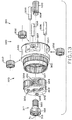
- primary planetary stage 370 With input component seated in engagement with planet gears 324 and planet gears 324 seated in ring gear 327, primary planetary stage 370 is fully assembled and forms as a portion of planetary reduction assembly 360. Combination component 340 and the other components included in planetary reduction assembly 360 are shown in the exploded view of Fig. 13 .
- secondary planet gears 332 are received within planet gear carrier 334, which is disposed at the output-side axial end of component 340 (i.e., opposite ring gear 327).
- the central bores formed in planet gears 332 are aligned with respective axle apertures 337, as illustrated by a comparison of Figs. 13 and 14 , and gear axles 336 are passed through apertures 337 and the bores of planet gears 332 to rotatably couple planet gears 332 to planet gear carrier 334.
- Bearings may be interposed between planet gears 332 and their respective axles 336 to promote smooth rotation of gears 332, similar to bearings 323 described above.
- Secondary sun gear 330 is then advanced axially into the opening formed in the axial end of combination component 340 such that its exterior splines are intermeshingly engaged with the corresponding exterior splines of respective planet gears 332.
- Secondary sun gear 330 also includes interstage splines 358 ( Fig. 13 ), which intermeshingly engage with correspondingly formed interstage splines 359 of planet gear carrier 326 when sun gear 330 is in its fully seated position within combination component 340.
- Interstage splines 358, 359 cooperate to rotatably fix primary planet gear carrier 326 to secondary sun gear 330, which also functionally couples the primary and secondary planetary stages 370, 380.
- secondary planetary stage 380 that are part of planetary reduction assembly 360 are assembled, and planetary reduction assembly 360 is complete.
- planet gears 332 are engaged with secondary ring gear 338 as described below, but ring gear 338 is not a part of the self-contained assembly 360.
- Fig. 14 illustrates planetary reduction assembly 360 is in its fully assembled configuration, together with additional components of wheel drive 310.
- hub 314 is rotatably received upon spindle 312 as described herein.
- bearing 342 is received on the outer surface of spindle 312 prior to installation of hub 314, and hub 314 cooperates with spindle 312 to axially fix bearing 342 in its designated location.
- Bearing 344 is installed on the opposite axial end of hub 314 as shown in Fig. 12 , and fixed in place by bearing nut 372 and bearing nut washer 374.
- Planetary reduction assembly 360 is rotatably fixed to spindle 312 by engaging external coupling splines 362, which are formed around the exterior annular surface of combination component 340 near its input-side axial end, with corresponding internal coupling splines 364, which are formed around an interior annular surface of hub 314 near its output-side axial end.
- splined connection 366 is formed ( Fig. 12 ) which rotatably fixes planetary reduction assembly 360 to spindle 312.
- spindle 312 may itself be rotatably fixed by being mounted to an adjacent mounting surface, such as vehicle frame F ( Fig. 10 ).
- planetary reduction assembly 360 When planetary reduction assembly 360 is rotatably coupled to spindle 312 by splined connection 366, a small amount of radial play therebetween is allowed to occur, including during operation of wheel drive 310. As further described below, this radial play facilitates "automatic” or “self' adjustment of the relative positions among the rotating and non-rotating parts of wheel drive 310 during operation of wheel drive 310, thereby promoting even pressure around bearings 342, 344 such that bearings 342, 344 can be expected to wear evenly over time.
- Planetary housing 341 is installed to hub 314 by aligning the respective mounting holes 316 thereof, and passing fasteners through holes 316.
- housing 341 can be installed to hub 314 before planetary reduction assembly 360 is rotatably fixed to spindle 312.
- the inwardly facing splines of ring gear 338 intermeshingly engage with the outwardly facing splines of each respective secondary planet gear 332, thereby completing the assembly of secondary planetary stage 380.
- secondary ring gear 338 is formed as a separate part which is axially received and seated within planetary housing 341, though it is contemplated that housing 341 and ring gear 338 may be monolithically formed as a single component.
- cover 348 is received over the open axial end of housing 341, which protects the internal components of wheel drive 310 and axially constrains planetary reduction assembly 360 from movement toward the output side of wheel drive 310 during operation.
- combination component 340 is a monolithic, integrally formed component which may be produced, e.g., by preparing a casting to create the rough metal part and machining the high tolerance features, including ring gear 327, external coupling splines 362 and axle apertures 337.
- formation of primary ring gear 327 is less complex and less expensive because the tooling required to machine the individual splines of ring gear 327 need not traverse a significant axial distance into combination component 340. For example, in the case of ring gear 327, the tooling only needs to travel the axial extent of the ring gear splines themselves to create the desired feature.
- this type of construction can be used to efficiently ensure a high degree of coaxiality between the primary and secondary planetary stages 370, 380 as further described below.
- the casting of component 340 provides an input-side portion (home to primary stage 370 and including primary ring gear 327) which defines an input-side diameter which is smaller than the diameter of the opposing output-side portion (home to secondary stage 380 and including secondary planetary gear carrier 334).
- This disparity of diameters reflects the fact that primary planetary stage 370 operates at relatively high speeds and handles lower torque, and can therefore be smaller in size as compared to secondary planetary stage 380 which operates at relatively lower speeds and transmits greater nominal amounts of torque.
- the respective longitudinal axes of sun gear 320 and planet gear carrier 326 of primary planetary stage 370 are nominally coaxial with the longitudinal axis of combination component 340, and each of these longitudinal axes is nominally coaxial with longitudinal axis A 1 of wheel drive 310 upon assembly.
- the inwardly facing splines of ring gear 327 are machined with an appropriately tight tolerance to control the radial deviation of the longitudinal axes of sun gear 320 and planet gear carrier 326 from axis A 1.
- axle apertures 337 relative to longitudinal axis A 1 can be controlled in cooperation with the size and cylindricity of secondary planet gears 332 to constrain radial deviation of the longitudinal axes of secondary planet carrier 334 and secondary sun gear 330 from longitudinal axis A 1 to within a desired tolerance.
- a relatively more permissive radial tolerance is provided between combination component 340 and spindle 312 by splined connection 366 ( Fig. 12 ) formed between external coupling splines 362 ( Fig. 14 ) and internal coupling splines 364 ( Fig. 14 ).
- This relatively permissive tolerance at splined connection 366 allows planetary reduction assembly 360 to "float" radially with respect to spindle 312 upon assembly, within a desired nominal radial range. This radial float, in turn, allows hub 314 to self-align with respect to spindle 312 during operation of wheel drive 310, as further described below.
- bearings 342, 344, spindle 312, hub 314 and housing 341 ( Fig. 12 ) establish a natural radial alignment among these components in which bearings 342, 344 are evenly stressed around their peripheries, and peak stresses on bearings on 342, 344 are concomitantly minimized. If this natural radial alignment is maintained upon assembly of the remainder of wheel drive 310, as well as throughout its service life as bearings 342, 344 "wear in” during use, this stress minimization will persist and thereby maximize the life of bearings 342, 344.
- the permissive tolerance at splined connection 366 avoids disruption of this natural radial alignment by providing a nominal radial deviation between combination component 340 and spindle 312 that is greater than the expected nominal deviation resulting from the natural radial alignment of bearings 342, 344, spindle 312, hub 314 and housing 341 throughout the expected service life of bearings 342, 344, it being understood that the radial deviation (i.e., non-coaxiality) of the longitudinal axes of spindle 312 and hub 314 can be expected to increase as bearings 342, 344 age.
- the coaxiality of spindle 312, hub 314 and housing 341 may be substantially set and controlled by the function and operation of bearings 342, 344, because spindle 312, hub 314 and housing 341 are manufactured to greater coaxiality tolerances than bearings 342, 344 provide.
- the nominal coaxiality and concentricity of spindle 312, hub 314 and housing 341, as set by bearings 342, 344 and allowing only for the above-described "natural radial alignment,” may deviate by a known nominal tolerance over the rated service life of bearings.
- the nominal coaxiality of planetary reduction assembly 360 and spindle 312 may deviate by the designed tolerance of splined connection 366.
- the tolerance of splined connection 366 is greater than the tolerance of the "natural radial alignment" of wheel drive 310, ensuring that 342, 344 will not experience premature wear owing to an overly-rigid connection between hub 314, housing 341 and spindle 312.
- the spatial arrangement of spindle 312, bearings 342, 344, and hub 314/housing 341 is taken to be the basis for component alignment in wheel drive 310 between the non-rotating components (e.g., spindle 312, combination component 340) and the rotating output components (e.g., hub 314, housing 341).
- the radial positions of housing 341 and hub 314 relative to spindle 312, and therefore the concentricity of these components during operation of wheel drive 310, is primarily controlled by the pressure exerted by bearings 342, 344.
- combination component 340 including primary ring gear 327 and secondary planet gear carrier 334
- primary ring gear 327 and secondary planet gear carrier 334 are the "stationary" or non-rotating components of planetary stages 370, 380 respectively, it is appreciated that alternative designs may select other components as stationary components to be integrated into a combination component similar to combination component 340.
- a combination component in accordance with the present disclosure may include any one component from each of planetary stages 370, 380, with the selected components integrally and monolithically formed as a part of the combination component, as described above with respect to combination component 340.
- primary ring gear 327 may be rotatable and primary planet gear carrier 326 may be stationary, in which case primary planet gear carrier 326 would be integrally formed as a part of a combination component.
- secondary ring gear 338 can be integrally formed as a part of the combination component, and secondary planet carrier 334 may be rotatable.
- combination component 340 Any permutation or combination of components may be provided in combination component 340, provided that one component from each of planetary stages 370, 380 is included and planetary stages 370, 380 are operably linked to one another to cooperate in producing the final speed reduction of wheel drive 310.
- wheel drive 310 may be mounted to a vehicle via spindle 312, which may be fixed to an adjacent frame surface via mounting holes 313.
- a wheel W ( Fig. 10 ) may be mounted to hub 314 (and housing 341) via mounting holes 316 ( Fig. 14 ).
- spindle 312 For field service of any of the components of planetary assembly 360, it is expedient to leave spindle 312 fixed in place and avoid removal of the wheel W.
- Wheel drive 310 allows for such field service by granting access to the servicer of each component of planetary assembly 360 by removal of cover 348 to expose the otherwise enclosed interior of wheel drive 310.
- Combination component 334 can then be simply withdrawn from the interior of wheel drive 310, together with its associated attached components of assembly 360.
- such removal of combination component 334 and the other components of planetary assembly 360 leaves hub 314 and housing 341 fully supported upon spindle 312 via bearings 342, 344, such that field service of the components of assembly 360 may be peformed without otherwise supporting or disconnecting other wheel drive or vehicle components.
- combination component 334 and the associated components of planetary assembly 360 have been withdrawn from housing 341, further service is also enabled. For example, inspection of ring gear 338 and outer bearing 344 may be performed without further steps.
- the components of braking system 121, if provided are also accessible and may be serviced or replaced as appropriate.
- hub 314 and housing 341 can be easily removed from spindle 312 to provide access to both bearings 344 and 342, e.g., for service or replacement.
- bearing nut 347 ( Fig. 11 ) may be threadably disengaged from spindle 312 to allow bearing 344 (and any adjacent bearing washer) to be withdrawn from spindle 334, at which point hub 314 and housing 341 can also be withdrawn.
- Bearing 342 is then visible for inspection and can be withdrawn from its seated position on spindle 312 and inspected and/or replaced.
- spindle 312 may advantageously remain installed to the vehicle.
- Wheel drive 110 includes a spatial arrangement of internal components which allows roller bearings 142, 144 to be spaced apart from one another such that output-side bearing 144 is disposed at an axially outward position and relatively close to the center of gravity of wheel W mounted to hub 114 ( Fig. 10 ). As explained in detail below, this spacing of bearings 142, 144 results in a lower application of torque and stress thereupon during service, thereby enabling bearings 142, 144 to absorb heavier loads as bearings 142, 144 support the driven wheel W mounted to hub 114 and driven by ring gear 138.
- wheel drive 110 allows output-side bearing 144 to be disposed between hub 114 and ring gear 138, rather than between hub 114 and spindle 112.
- bearing 144 can utilize a larger cross-sectional area for support of driven wheel W ( Fig. 10 ) attached to hub 114 and ring gear 138, in turn facilitating the use of a stronger, more robust bearing at the output side of wheel drive 110.
- Spacing distance S B is the axial extent of the space between bearings 142, 144, i.e., the shortest distance between the respective outer surfaces of bearings 142, 144.
- Load spacing S B ' is the axial extent between intersection points between longitudinal axis A 1 and bearing load lines 142L, 144L respectively.
- Load lines 142L, 144L extend perpendicularly to the longitudinal axes defined by bearing rollers 143, 145, respectively, and originate halfway along the axial extent of rollers 143, 145, respectively. Load lines 142L, 144L extend radially inwardly to the respective intersection points with axis A 1.
- load spacing S B ' can be made larger by canting bearing rollers 143, 145, further out of parallel relationship with axis A 1 , and smaller by canting bearing rollers 143, 145 toward a parallel orientation with respect to axis A 1.
- Such canting affects the ability of bearings 142, 144 to absorb forces and stresses without damage, with larger load spacing S B ' associated with increased ability to absorb bending moments but decreased ability to absorb radial forces.
- An increase in spacing distance S B results in a corresponding increase in load spacing S B ' for any given arrangement of rollers 143, 145, while also preserving the full radial capabilities of the roller arrangement. This, in turn, facilitates greater ability for bearings 142, 144 to absorb the chaotic forces and stresses which may be exerted when used on a vehicle.
- Center line BC is axially positioned such that, when a radial force is applied to bearings 142, 144 over time, bearings 142, 144 can be expected to wear at an even rate.
- center line BC would be halfway between bearings 142, 144 (i.e., oriented at one-half of distance S B ).
- bearings 142, 144 have differing load ratings.
- Output-side bearing 144 is disposed between the outer wall of spindle 112 and the inner wall of ring gear 138, which is a relatively larger radial and axial space such that output-side bearing 144 has a larger overall cross-section compared to input-side bearing 142, which is disposed in the relatively smaller space between the outer wall of spindle 112 and the inner wall of hub 114.
- the larger cross-section of output-side bearing 144 enables utilization of a higher load rating with respect to input-side bearing 142.
- center line BC is biased toward the bearing with a higher load rating as illustrated in Fig. 2 .
- the amount of such biasing is proportional to the relative strengths of the bearings, i.e., if bearing 144 has a load rating twice that of bearing 142, center line SB is twice as far from bearing 142 as it is from bearing 144.
- Output-side bearing 144 is axially spaced from mounting holes 116 of output hub 114 toward the output side of wheel drive 110, such that output-side bearing 144 is positioned within the axial extent of wheel W (i.e., the distance along the axis of wheel rotation from the outboard-most point of wheel W to the inboard-most point thereof, as shown in Fig. 10 ).
- This positioning is enabled by the placement of primary planetary stage 170 within spindle 112, which in turn allows output-side bearing 144 to be placed at a common axial position with primary stage 170 as illustrated in Figs. 2 and 4 .
- this common axial position is such that the axial extent of bearing 144 is substantially subsumed by the axial extent of primary stage 170.
- bearings 142, 144 dispose the functional bearing center line BC also within the axial extent of wheel W.
- Load spacing S B /S B ' and the positioning of bearings 142, 144 cooperate to minimize stresses exerted on bearings 142, 144 during operation of wheel drive 110, as described in detail below.
- spacing distance S B may be as little as 0.419 inches, 0.75 inches or 1 inch, and as large as 1.5 inches, 1.75 inches, or 2.00 inches, or may be any distance within any range defined by any of the foregoing values.
- Each bearing 142, 144 defines bore diameter D B sized to fittingly encircle spindle 112.
- Diameter D B of bearings 142, 144 is slightly larger than the outer diameter of spindle 112, such that bearings 142, 144 slide easily over the outer surface of spindle 112.
- diameter D B may be as small as 2.0 inches, 3.0 inches or 4.0 inches, and as large as 6.0 inches, 7.0 inches, or 8.0 inches, or may have any bore size within any range defined by any of the foregoing values.
- the present arrangement of components within wheel drive 110 facilitates the bearing spacing S B between bearings 142, 144, which in turn shortens the axial distance between the most axial outward point of the assembly (i.e., the approximate location of the wheel center of gravity of driven wheel W as shown in Fig. 10 ) and output-side bearing 144/center line BC.
- output-side bearing 144 and center line BC are placed closer to the point of load application upon wheel W attached to hub 114, which in turn reduces the bending torque and minimizes the stresses on bearings 142, 144.
- wheel drive 110 Increasing the distance between the two bearings 142, 144 and thus decreasing the distance between center line BC and the center of gravity of wheel W is an effective way to decrease the stresses on the bearings 142, 144 while maintaining the other dimensions of wheel drive 110 according to industry standards and/or application demands.
- the overall size and configuration of wheel drive 110 are imposed as design constraints because wheel drive 110 must be compatible with existing vehicle frame mounting geometry and/or existing available vehicle wheels.
- spindle 112 includes mounting holes 113 arranged annularly around a spindle bolt circle having diameter D S
- hub 114 and ring gear 138 similarly include mounting holes 116 arranged annularly around a hub bolt circle having diameter D H .
- diameters D H and D S are between 6.5 inches and 17.0 inches.
- wheel drive 110 defines overall axial length L, which in the exemplary embodiments noted above is between 7.5 inches and 15.0 inches.
- the present wheel drive arrangement increases spacing S B without making any other changes to overall size and configuration of wheel drive 110, including bolt circle diameters D H and D S and overall axial length L, such that wheel drive 110 provides greater strength and capacity for bearings 142, 144 while maintaining the ability to fit wheel drive 110 into existing vehicle infrastructure.
- wheel drives 110 can be provided in a wide range of overall sizes. Some very small sizes may be provided for passenger vehicle applications, such as pickup trucks and other off-road applications, while very large sizes may be provided for earth moving equipment, large construction vehicle, and the like.
- the nominal spacing S B of bearings 142, 144 increases as the other components increase in size. Accordingly, one way to express the present wide bearing spacing in the context of a wide range of wheel drive sizes is as a ratio of spacing S B ' and/or spacing S B to bearing bore diameter D B .
- a higher S B :D B ratio or S B ':D B ratio is indicative of a relatively greater relative spacing between bearings 142, 144, and is also indicative of the output-side bearing 144 and center line BC being closer to the center of gravity of driven wheel W ( Fig. 10 ). Accordingly, a greater S B :D B ratio or S B ':D B ratio generally results in higher bearing support capability for a given wheel drive size.
- the S B :D B ratio may be between 0.11 and 0.50, which results in a stronger and more robust wheel drive 110 as compared to existing designs.
- the S B ':D B ratio may be between 0.690 and 1.090.
- wheel drive 110 indicative of wide spacing S B is the positioning of output side bearing 144 and center line BC relative to mounting holes 116 for driven wheel W at hub 114 and ring gear 138.
- bearing 144 is disposed axially outward relative to mounting holes 116, thereby placing bearing 144 and bearing load center line BC within the axial extent of driven wheel W when wheel W is mounted to wheel drive 110 (as shown in Fig. 10 ).
- ring gear 138 and cover 148 are both contained within the generally cylindrical cavity C created by wheel W on a typical installation, such that ring gear 138 is directly radially inward of the contact patch P between tire T and the adjacent ground G.
- a line taken from the center of contact patch P and perpendicular to ground G intersects ring gear 138.
- the placing of bearing 144 axially outward of mounting holes 116 disposes bearing 144 within the axial extent of wheel W, thereby minimizing or eliminating the axial spacing between the application of force to wheel W and center line BC. This, in turn, minimizes or eliminates the lever arm which would result in a torque being placed upon bearings 142, 144, such that bearings 142, 144 need only handle the radial inward force applied by wheel W rather than such force together with a resultant torque.
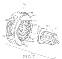
- Figs. 7-8C illustrate short-stroke disconnect mechanism that can be used to disengage sun gear 130 of secondary planetary stage 180 from planet gear carrier 126 of primary stage 170, thereby allowing wheel hub 114 and wheel W to disengage from the influence of the vehicle power source. When so disengaged, the attached wheel W can spin freely with respect to spindle 112, such as for towing the vehicle.
- the present arrangement utilizes primary/secondary coupler component 129 which facilitates a short disengagement stroke by utilizing face splines 131 protruding axially away from sun gear portion 130. Face splines 131 selectively engage corresponding recesses 125 formed in an axial end surface of primary planet gear carrier 126 to rotationally fix primary stage 170 to secondary stage 180, as further detailed below.
- sun gear portion 130 and face splines 131 are monolithically formed as a single piece, namely, primary/secondary coupler component 129.
- recesses 125 are monolithically formed as a part of primary planet gear carrier 126. This monolithic construction contributes to long life and high strength of the short-stroke disconnection mechanism, as well as minimizing rotational backlash through the system when short-stroke disconnection mechanism is subjected to forces and torques. Moreover, as illustrated in Figs.
- Figs. 8A-8B illustrate the transition from engagement to disengagement of the short-stroke disconnection mechanism.
- the mechanism is shown in the actuated configuration, in which face splines 131 are received within recesses 125.
- primary/secondary coupler component 129 is rotationally fixed to primary planet gear carrier 126, such that torque output from primary planetary stage 170 is input into secondary planetary stage 180 as described above.
- Component 129 is maintained in this engaged position by spring 135, which is compressed between an internal bore formed in sun gear portion 130 and spring plunger 139, which is fixed to lever 150 as detailed below.
- Fig. 8B shows face splines 131 of sun gear 130 withdrawn from engagement with corresponding recesses 125.
- this withdrawn engagement is effected by rotating lever 150 to axially displace primary/secondary coupler component 129 against the biasing force of spring 135 such that face splines 131 move axially toward the output side of wheel drive 110, thereby withdrawing splines 131 axially out of recesses 125.
- any torque imparted to gear carrier 126 from input component 117 will no longer input into the secondary planetary stage 180, such that ring gear 138 is effectively decoupled from the vehicle power source and will not be driven by input from input component 117.
- the present short-stroke withdrawal mechanism allows wheel drive 110 to be reconfigured between the engaged position of Fig. 8A , in which hub 114 and ring gear 138 are driven by input component 117, and the disengaged position of Fig. 8B , in which the input component 117 is functionally decoupled from hub 114 and ring gear 138 (such that the vehicle using wheel drive 110 can be towed or pushed without interference from the braking system 121, vehicle engine or transmission as noted above).
- decoupling ring gear 138 from the power source avoids rotation of the components of primary planetary stage 170 during rotation of wheel W ( Fig. 10 ), thereby preventing wear of such components when wheel W is rotating and wheel drive 110 is not being powered by input component 117.
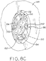
- Fig. 8C illustrates the center portion of wheel drive cover 148, which includes cam surfaces 152 and lands 154 within recess 156.
- spring plunger 139 (which is axially fixed to lever 150) is drawn outwardly, carrying primary/secondary coupler component 129 with it. This compresses spring 135, and simultaneously withdraws face splines 131 out of engagement with the corresponding recesses 125 formed in primary planet gear carrier 126. Resting lever 150 upon lands 154 maintains the disconnect mechanism in the disengaged state, and rotating lever 150 back down cam surfaces 152 allow spring 135 to bias lever 150, spring plunger 139 and primary/secondary coupler component 129 back in to the engaged state.
- Wheel drive 110 utilizes primary and secondary planetary stages 170, 180 to achieve a final reduced speed and increased torque of ring gear 138 with respect to input component 117, as described above.
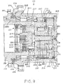
- This arrangement includes primary stage 270 contained within spindle 212, secondary planetary stage 280 disposed at the axial outward end of wheel drive 210 and operably connected to primary stage 270 via secondary sun gear 230, and tertiary stage 290 operably connected to secondary stage 280 via tertiary sun gear 260.
- Secondary and tertiary stages 280 and 290 cooperate to drive ring gear 238.
- Primary planetary stage 270 is functionally identical to primary planetary stage 170, except that sun gear 220 is larger than sun gear 120 and planet gears 224 are concomitantly smaller than planet gears 124. It is, of course, contemplated that primary planetary stage 170 of wheel drive 110 could be identical to primary planetary stage 270. Moreover, any arrangement of planetary components may be used to provide a desired gear reduction as required or desired for a particular design.
- Secondary planetary stage 280 is arranged as the output-side planetary stage, i.e., closest to the outboard side of the wheel ( Fig. 10 ), and is disposed axially outside of spindle 212. Secondary stage 280 receives power from primary planet gear carrier 226, via primary/secondary coupler component 229 in similar fashion to wheel drive 110 described above, except that secondary sun gear 230 is a separate component rotatably fixed to coupler component 229 rather than being integrally formed therewith.
- Secondary sun gear 230 includes outer splines with engage correspondingly formed outer splines of three planet gears 232, causing planet gears 232 to rotate about planet gear axles 236 within ring gear 238. Similar to Fig. 2 illustrating wheel drive 110, Fig. 9 shows only two planet gears 232 in the cross-sectional view, with the lower gear 232 shown in section and the upper gear 232 partially obscured by adjacent components. However, unlike the primary stage having stationary ring gear 227 formed along the inner wall of spindle 212, ring gear 238 of secondary stage 280 rotates as a result of the rotation of internal planet gears 232.
- gear carrier 234 of secondary planetary stage 280 rotates as a result of the rotation of internal planet gears 232 in addition to ring gear 238.
- secondary planetary stage 280 has both a rotating ring gear 238 and a rotating gear carrier 234.
- Gear carrier 234 is rotatably fixed to sun gear 250 of tertiary planetary stage 290 and rotates sun gear 250.
- tertiary sun gear 250 Splines formed on the outer surface of tertiary sun gear 250 engage correspondingly formed external splines on the three planet gears 252, which are in turn supported by and rotate about gear axles 256 in gear carrier 254.
- Tertiary gear carrier 254 is integrally formed as part of spindle 212, and is therefore stationary in the context of wheel drive 210.
- Tertiary planet gears 252 rotate about gear axles 256 while engaging the internal splines of ring gear 238 to aid in rotation of ring gear 238.
- planet gears 232 and 252 of both secondary and tertiary planetary stages 270, 280 cooperate to drive ring gear 238, with secondary planet gears 232 allowed to circumnavigate secondary sun gear 230 while tertiary planet gears 252 do not circumnavigate.
- rotation of ring gear 238 forms the final output of wheel drive 210, and rotates wheel W at a rotational speed that has been reduced three times - once by each of the three planetary stages 270, 280, and 290.
Landscapes
- Engineering & Computer Science (AREA)
- Mechanical Engineering (AREA)
- General Engineering & Computer Science (AREA)
- Chemical & Material Sciences (AREA)
- Combustion & Propulsion (AREA)
- Transportation (AREA)
- Retarders (AREA)
Description
- The present invention relates to vehicle power transmission units, and, more particularly, to wheel-mounted gear reduction units.
- Wheel drives are used to provide gear reduction at or near the point of service, such as at the hub of a driven wheel. Wheel drives may be used for the large driven wheels commonly found on construction equipment and earth moving vehicles, for example, or for auger bits used in drilling post holes in the ground.
- International Patent Application Publication No.
WO 2014/065851 describes a wheel drive arranged to provide a wide axial spacing between the internal bearings used to rotatably support the hub of the wheel drive on the spindle thereof. This wide axial spacing and other features of the wheel drive provide reduced torque and stress on the bearings during service, thereby enabling the bearings to absorb heavier loads while supporting a driven wheel mounted to the hub of the wheel drive. The wheel drive includes primary and secondary planetary reduction stages which operate to respectively reduce the speed and increase the torque applied to the hub (and wheel). Each planetary stage includes a ring gear and a sun gear with a plurality of planet gears disposed therebetween and supported by a planet gear carrier. - The wheel drive described in
WO 2014/065851 utilizes a spindle which is integrally and monolithically formed as a single part together with the primary stage ring gear and secondary stage planet carrier. This monolithically formed spindle, ring gear and planet carrier is a large and complex part which may complicate the production and assembly of the wheel drive in some configurations. - The present invention provides a speed-reducing transmission unit according to claim1, a planetary reduction assembly according to claim 8, a method of manufacturing a speed-reducing transmission unit according to
claim 14 and a method of servicing a speed-reducing transmission unit according toclaim 18. - The above-mentioned and other features and advantages of the present invention and the manner of attaining them, will become more apparent and the invention itself will be better understood by reference to the following description of an embodiment of the invention taken in conjunction with the accompanying drawings, wherein:
-
Fig. 1 is a cross-sectional, elevation view of a known wheel drive; -
Fig. 2 is a cross-sectional, elevation view of a two-stage wheel drive made in accordance with the present disclosure; -
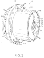
Fig. 3 is an output-side, perspective view of the wheel drive shown inFig. 2 ; -
Fig. 4 is an output-side, perspective, cross-sectional view of the wheel drive shown inFig. 2 , in which the wheel drive cover has been removed for clarity; -
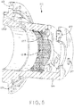
Fig. 5 is an output-side, perspective, cross-sectional view of the spindle of the wheel drive shown inFig. 2 ; -
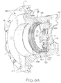
Fig. 6A is an input-side, perspective, cross-sectional view of the spindle shown inFig. 5 , together with the primary planetary stage components from the wheel drive ofFig. 2 ; -
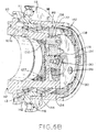
Fig. 6B is an output-side, perspective, cross-sectional view of the spindle and primary planetary stage shown inFig. 6B , together with the secondary planetary stage and related components; -
Fig. 7 is a perspective, cross-sectional view of the primary planetary stage components and the secondary sun gear shown inFig. 2 , shown with the sun gear's splines withdrawn from corresponding recesses in the primary gear carrier; -
Fig. 8A is a cross-sectional, partial elevation view of the wheel drive shown inFig. 2 , illustrating the short-stroke disconnect mechanism in an engaged configuration; -
Fig. 8B is a cross-sectional, partial elevation view of the wheel drive shown inFig. 2 , illustrating the short-stroke disconnect mechanism in a disengaged configuration; -
Fig. 8C is a cross-sectional, partial perspective view of the wheel drive shown inFig. 3 , illustrating a user interface for the short-stroke disconnect mechanism shown inFigs. 8A and 8B ; -
Fig. 9 is a cross-sectional, elevation view of a three-stage wheel drive made in accordance with the present disclosure; -
Fig. 10 is a partial cross-section, elevation view of a wheel drive made in accordance with the present disclosure attached to a vehicle frame and having a wheel attached to the wheel drive; -
Fig. 11 is a cross-section, perspective view of another wheel drive in accordance with the present disclosure, including a planetary reduction subassembly selectively rotatably fixable to the wheel drive spindle; -
Fig. 12 is a cross-section, elevation view of the wheel drive shown inFig. 11 ; -
Fig. 13 is an exploded view of the planetary reduction subassembly used in the wheel drive ofFig. 11 , illustrating a combination component and planetary reduction components which mount thereto; and -
Fig. 14 is an exploded, perspective, partial section view of components of the wheel drive shown inFig. 11 , illustrating the planetary reduction subassembly ofFig. 13 and the wheel drive components which mount thereto. - Corresponding reference characters indicate corresponding parts throughout the several views. The exemplifications set out herein illustrate embodiments of the disclosure and such exemplifications are not to be construed as limiting the scope of the invention in any manner.
- As shown in
Figs. 11-14 wheel drive 310 includeshub 314 rotatably mounted tospindle 312, with a gear reduction system includingprimary stage 370 andsecondary stage 380.Combination component 340 is a single, monolithic part incorporating one of the functional components of eachstage planetary stages planetary reduction assembly 360 as described in detail below.Combination component 340 also mounts to spindle 112 in a rotatably fixed configuration viasplined connection 366, which provides some tolerance to allow for wear inroller bearings -
Wheel drives monolithic spindle 112 and no analog to combination component 240. The features ofwheel drives wheel drives other wheel drives - Various components of
wheel drives spindles hubs combination component 340,brake systems input components primary gear carrier bearings secondary coupler component ring gears housing 341,seals outer covers respective wheel drive Figs. 2 ,4 ,9 ,11 and12 . - As best seen in
Fig. 3 ,wheel drive 110 includesspindle 112, which affixes to a vehicle frame F (Fig. 10 ) viamounting holes 113, andhub 114, which affixes to a driven wheel W viamounting holes 116 and rotates with respect tospindle 112 about longitudinal axis A1 ofwheel drive 110. Driven wheel W andwheel hub 114 are also affixed toring gear 138, as described further below, such that wheel W andwheel hub 114 are powered by rotation ofring gear 138 about axis A1. In other embodiments,wheel drive 110 may be used as speed reducer for other driven components or devices, such as augers. - Referring to
Fig. 2 ,wheel hub 114 is rotatably mounted tospindle 112 viaroller bearings spindle 112 and an inner surface ofhub 114. Output-side bearing 144 is also mounted upon and directly abuts the outer surface ofspindle 112 as illustrated, but is abutted at its radial outward surface byring gear 138 rather thanhub 114. Thus, input-side bearing 142 is both axially constrained (i.e., prevented from axial movement) and radially constrained (i.e., prevented from radially outward movement or expansion) by cooperation of adjacent surfaces ofspindle 112 andhub 114. However, output-side bearing 144 is only axially constrained byspindle 112 andhub 114, while radial constraint is provided byring gear 138. As described in further detail below,bearings -
Wheel drive 110 includes two planetary gear stages, namely primaryplanetary stage 170 and secondaryplanetary stage 180, which each contribute to the overall gear reduction betweeninput component 117 andring gear 138. Primaryplanetary stage 170 receives powered input frominput component 117 and produces an intermediate output having reduced rotational speed and concomitantly higher torque as compared toinput component 117. As described in further detail below, this intermediate output selectively provides the powered input to secondaryplanetary stage 180, by selectively rotationally fixing primary planet gear carrier 126 (which is the output component of primary stage 170) to secondary sun gear 130 (which is the input component of secondary stage 180).Secondary planet stage 180 in turn produces a final output having reduced rotational speed and increased torque with respect to the intermediate output of primaryplanetary stage 170. The final output is transmitted toring gear 138, which is fixed towheel hub 114. - Thus, the final output of
wheel drive 110 rotates driven wheel W (Fig. 10 ) at a rotational speed that has been reduced twice - once by each of the twoplanetary stages wheel drive 110 as a "two stage" system, though it is contemplated that systems with other reduction mechanisms may be used. For example, a single stage wheel drive having only one planetary stage may be used in designs requiring relatively smaller overall reduction ratios, while multiple-stage wheel drives having three or more stages may be used where larger overall reduction ratios are desired. Where a single-stage wheel drive is desired, a ring gear may form the output component (as is the case withsecondary stage 180 described herein), or a planet gear carrier may form the output component (as is the case withprimary stage 170 described herein). A three-stage wheel drive 210 is shown inFig. 9 and described further below. - Turning to
Figs. 2 and4 , the configuration of both primaryplanetary stage 170 and secondaryplanetary stage 180 is illustrated. First, primaryplanetary stage 170 receives power frominput component 117 which includesinput coupler 118 andsun gear 120 monolithically formed as a single part. An externally splined input shaft (not shown) transmits power from a vehicle power source to the internal splines ofinput coupler 118 to rotatesun gear 120. External splines formed onsun gear 120 engage correspondingly formed external splines on a plurality of planet gears 124, such as threeplanet gears 124 in the illustrated embodiment. Only twoplanet gears 124 are visible within the cross sectional views ofFigs. 2 ,4 and6A , it being understood that alower planet gear 124 is shown in section, anupper planet gear 124 is shown behind the cross sectional plane and partially obscured bysun gear 120, and a second upper planet gear is not shown in the sectioned view. As best shown inFig. 6 , the external splines of planet gears 124 also engagering gear 127, which is integrally formed along the inner wall ofspindle 112 as further described below. Planet gears 124 are held in their respective positions byplanet gear carrier 126, and are rotatable about the respective planet gear longitudinal axes viaplanet gear axles 128.Bearings 123 may be interposed between planet gears 124 andaxles 128 to facilitate rotation therebetween. - Rotation of
sun gear 120 causes planet gears 124 to rotate aboutplanet gear axles 128, as well as to rotate about longitudinal axis A1 withinstationary ring gear 127. Becausespindle 112 is mounted to the vehicle frame F (Fig. 10 ) andring gear 127 is monolithically formed as part ofspindle 112,ring gear 127 is a stationary component in the context of primaryplanetary stage 170 andwheel drive 110. Accordingly, planet gears 124 are free to circumnavigatesun gear 120 while rotating about axis A1 and, in doing so, causeprimary gear carrier 126 to rotate about axis A1 at the speed of such circumnavigation.Primary gear carrier 126 is selectively rotatably fixed tosun gear 130, and therefore provides the input to drive rotation of secondaryplanetary stage 180, as further detailed below. - Turning to
Figs. 5 and6B , secondaryplanetary stage 180 is arranged similarly to primaryplanetary stage 170. As described further below, however, secondaryplanetary stage 180 includesgear carrier 134 which is integrally and monolithically formed as a part ofspindle 112, and is therefore stationary in the context ofwheel drive 110. For secondaryplanetary stage 180,ring gear 138 is the rotatable component which serves as the output ofsecondary stage 180. - Similar to
primary stage 170 described above, external splines ofsecondary sun gear 130 engage with external splines formed on each of threeplanet gears 132 which are in turn engaged with the internal splines formed inring gear 138. Likeprimary stage 170, only twoplanet gears 132 are visible in the cross-sectional views ofFigs. 2 ,4 and6B , with theupper planet gear 132 shown in section and thelower planet gear 132 partially obscured by adjacent components. Rotation ofsecondary sun gear 130 causes planet gears 132 to rotate aboutplanetary gear axles 136, but such rotation cannot cause circumnavigation of planet gears 132 about axis A1 becauseplanet gear carrier 134 is fixed as noted above. Instead, rotation of planet gears 132 drives rotation ofring gear 138. Thus, unlikeprimary stage 170 withstationary ring gear 127 andgear carrier 126 as the output component,secondary stage 180 utilizesring gear 138 as its output component whilegear carrier 134 remains stationary.Bearings 133 may be interposed between planet gears 132 andaxles 136 to facilitate rotation therebetween. -
Spindle 112 therefore serves multiple roles inwheel drive 110, including the role of a stationary component in each of theplanetary stages 170, 180 (i.e.,ring gear 127 andplanet gear carrier 134 respectively). For clarity,Fig. 5 illustratesspindle 112 in cross-section without other components, whileFigs. 6A and6B showspindle 112 with only primary and secondaryplanetary stages - As most clearly illustrated in
Figs. 5 and6A ,stationary ring gear 127 is integrally formed inspindle 112 for interaction with the other components of primaryplanetary stage 170. Unlikespindle 12 ofwheel drive 10,spindle 112 ofwheel drive 110 encircles primaryplanetary stage 170.Figs. 5 and6B illustrate thatgear carrier 134 as an integrally, monolithically formed part ofspindle 112, withgear carrier 134 receivingplanetary gear axles 136 through axle apertures 137 (Fig. 5 ). In short,spindle 112 serves as both a housing and a support structure for bothplanetary stages planetary stage 170 axially rotating within the cavity ofspindle 112 and secondary planet gears 132 rotating aboutgear axles 136 received withinapertures 137 formed in spindle 112 (Fig. 5 ). As described in further detail below, this arrangement of components moves primaryplanetary stage 170 intospindle 112 such that the space radially outside ofspindle 112 normally occupied byprimary stage 170 is made available, which in turn allows output-side bearing 144 to occupy the space normally occupied byprimary stage 170. -
Wheel drive 110 may be used outside, and may therefore be exposed to the elements.Wheel drive 110 includesseal 146, best shown inFig. 2 , disposed betweenhub 114 andspindle 112. Referring toFigs. 2 and3 ,outer cover 148 is fitted on the axial outward end ofring gear 138.Seal 146 andouter cover 148 cooperate to retain lubricant contained withinwheel drive 110, while also preventing dust, moisture, and other contaminants from infiltrating the interior ofwheel drive 110. - As best seen in
Fig. 2 , wheel drive 110 optionally includesbrake system 121 operable to selectively arrest rotation ofinput component 117.Clutch pack 121A includes alternating clutch plates engaginginner splines 121B (Fig. 5 ) formed on the inner surface ofspindle 112 or outer splines formed oncoupler portion 118 ofinput component 117.Springs 121C, which may be provided as Belleville-type springs, urgeclutch release component 121E into engagement withclutch pack 121A, biasing the alternating clutch plates into abutting engagement with one another. This creates frictional resistance to rotation ofinput component 117.Hydraulic line 121D selectively provides pressurized fluid to moveclutch release component 121E axially toward the input side ofwheel drive 110, against the biasing force ofsprings 121C. This allows the clutch plates ofclutch pack 121A to spread apart from one another, relieving the friction therebetween and allowinginput component 117 to rotate. - Referring now to
Figs. 11 and12 ,wheel drive 310 includesplanetary reduction assembly 360 includingcombination component 340, primaryplanetary stage 370 and secondaryplanetary stage 380.Combination component 340 provides a framework for supporting and aligning the components ofplanetary stages wheel drive 310 as a self-contained unit. In the illustrated embodiment and as further described below,primary ring gear 327 of primaryplanetary stage 370 andplanet gear carrier 334 of secondaryplanetary stage 380 are integrally formed as a part ofcombination component 340, which is a monolithic part. With the exception ofsecondary ring gear 338,planetary reduction assembly 360 includes all the additional components of primary and secondaryplanetary stages wheel drive 310 via asplined connection 366 with spindle 312 (Fig. 12 ). Further details of the assembly and implementation ofwheel drive 310 are described in further detail below. - Except as otherwise noted herein, reference numbers used to refer to components of
wheel drive 310 are correspondingly used in reference to wheel drives 110, 210 described herein, except with 100 and 200 added thereto respectively. The features of wheel drives 110, 210 and 310 may be used in any combination or permutation as required or desired for a particular application. - However, unlike the single, monolithic component shown in wheel drives 110, 210 including a spindle (112, 212), primary ring gear (127, 227) and secondary planet carrier (134, 234),
spindle 312 ofwheel drive 310 is a separate component fromcombination component 340 and is selectively rotatably fixed thereto viasplined connection 366, as shown inFig. 12 . As described in further detail below, this configuration both simplifies the manufacture and assembly ofwheel drive 310, while also providing enhanced operation and function during operation ofwheel drive 310. - To assemble primary
planetary stage 370, planet gears 324 are first rotatably coupled toplanet gear carrier 326 viaaxles 328 as illustrated inFig. 13 .Bearings 323 may be interposed betweenaxles 328 and eachrespective planet gear 324, as shown inFigs. 11 and12 . The resulting subassembly includes planet gears 324,carrier 326 andaxles 328, which is then axially received intoprimary ring gear 327 disposed immediately adjacent the input-side axial end ofcomponent 340. As shown by a comparison ofFigs. 13 and14 , the exterior teeth of eachrespective planet gear 324 intermesh with the adjacent interior teeth ofring gear 327 as the subassembly is advanced intocomponent 340 to the fully seated position ofFig. 14 . -
Input component 317 is received through the central opening formed at the input side ofplanet gear carrier 326, such that the exterior splines ofsun gear 320 intermeshingly engage with the exterior splines of each of the respective planet gears 324. In the illustrated embodiment,input component 317 also includescoupler portion 318 which extends axially outside ofcombination component 340 as illustrated inFig. 14 .Coupler portion 318 includes interior splines sized and configured to receive a power input shaft (not shown), and exterior brake splines 368 sized and configured to engage a braking system (not shown) similar tobraking systems - With input component seated in engagement with
planet gears 324 and planet gears 324 seated inring gear 327, primaryplanetary stage 370 is fully assembled and forms as a portion ofplanetary reduction assembly 360.Combination component 340 and the other components included inplanetary reduction assembly 360 are shown in the exploded view ofFig. 13 . - To assemble secondary
planetary stage 380, secondary planet gears 332 are received withinplanet gear carrier 334, which is disposed at the output-side axial end of component 340 (i.e., opposite ring gear 327). The central bores formed in planet gears 332 are aligned withrespective axle apertures 337, as illustrated by a comparison ofFigs. 13 and14 , andgear axles 336 are passed throughapertures 337 and the bores of planet gears 332 to rotatably couple planet gears 332 toplanet gear carrier 334. Bearings (not shown) may be interposed between planet gears 332 and theirrespective axles 336 to promote smooth rotation ofgears 332, similar tobearings 323 described above.Secondary sun gear 330 is then advanced axially into the opening formed in the axial end ofcombination component 340 such that its exterior splines are intermeshingly engaged with the corresponding exterior splines of respective planet gears 332. -
Secondary sun gear 330 also includes interstage splines 358 (Fig. 13 ), which intermeshingly engage with correspondingly formedinterstage splines 359 ofplanet gear carrier 326 whensun gear 330 is in its fully seated position withincombination component 340. Interstage splines 358, 359 cooperate to rotatably fix primaryplanet gear carrier 326 tosecondary sun gear 330, which also functionally couples the primary and secondaryplanetary stages - At this point, all components of secondary
planetary stage 380 that are part ofplanetary reduction assembly 360 are assembled, andplanetary reduction assembly 360 is complete. To functionally complete secondaryplanetary stage 380, planet gears 332 are engaged withsecondary ring gear 338 as described below, butring gear 338 is not a part of the self-containedassembly 360. -
Fig. 14 illustratesplanetary reduction assembly 360 is in its fully assembled configuration, together with additional components ofwheel drive 310. To assemblewheel drive 310,hub 314 is rotatably received uponspindle 312 as described herein. In the illustrated embodiment, bearing 342 is received on the outer surface ofspindle 312 prior to installation ofhub 314, andhub 314 cooperates withspindle 312 to axially fix bearing 342 in its designated location. Bearing 344 is installed on the opposite axial end ofhub 314 as shown inFig. 12 , and fixed in place by bearingnut 372 and bearingnut washer 374. -
Planetary reduction assembly 360 is rotatably fixed tospindle 312 by engagingexternal coupling splines 362, which are formed around the exterior annular surface ofcombination component 340 near its input-side axial end, with correspondinginternal coupling splines 364, which are formed around an interior annular surface ofhub 314 near its output-side axial end. When splines 362, 364 are so engaged,splined connection 366 is formed (Fig. 12 ) which rotatably fixesplanetary reduction assembly 360 tospindle 312. As noted above with respect tospindle 112,spindle 312 may itself be rotatably fixed by being mounted to an adjacent mounting surface, such as vehicle frame F (Fig. 10 ). - When
planetary reduction assembly 360 is rotatably coupled tospindle 312 bysplined connection 366, a small amount of radial play therebetween is allowed to occur, including during operation ofwheel drive 310. As further described below, this radial play facilitates "automatic" or "self' adjustment of the relative positions among the rotating and non-rotating parts ofwheel drive 310 during operation ofwheel drive 310, thereby promoting even pressure aroundbearings bearings -
Planetary housing 341 is installed tohub 314 by aligning the respective mountingholes 316 thereof, and passing fasteners throughholes 316. Alternatively,housing 341 can be installed tohub 314 beforeplanetary reduction assembly 360 is rotatably fixed tospindle 312. When so assembled, the inwardly facing splines ofring gear 338 intermeshingly engage with the outwardly facing splines of each respectivesecondary planet gear 332, thereby completing the assembly of secondaryplanetary stage 380. In the illustrated embodiment ofFig. 14 ,secondary ring gear 338 is formed as a separate part which is axially received and seated withinplanetary housing 341, though it is contemplated thathousing 341 andring gear 338 may be monolithically formed as a single component. - Finally, cover 348 is received over the open axial end of
housing 341, which protects the internal components ofwheel drive 310 and axially constrainsplanetary reduction assembly 360 from movement toward the output side ofwheel drive 310 during operation. - As noted above,
combination component 340 is a monolithic, integrally formed component which may be produced, e.g., by preparing a casting to create the rough metal part and machining the high tolerance features, includingring gear 327,external coupling splines 362 andaxle apertures 337. As compared withspindles primary ring gear 327 is less complex and less expensive because the tooling required to machine the individual splines ofring gear 327 need not traverse a significant axial distance intocombination component 340. For example, in the case ofring gear 327, the tooling only needs to travel the axial extent of the ring gear splines themselves to create the desired feature. In addition, this type of construction can be used to efficiently ensure a high degree of coaxiality between the primary and secondaryplanetary stages Fig. 13 , the casting ofcomponent 340 provides an input-side portion (home toprimary stage 370 and including primary ring gear 327) which defines an input-side diameter which is smaller than the diameter of the opposing output-side portion (home tosecondary stage 380 and including secondary planetary gear carrier 334). This disparity of diameters reflects the fact that primaryplanetary stage 370 operates at relatively high speeds and handles lower torque, and can therefore be smaller in size as compared to secondaryplanetary stage 380 which operates at relatively lower speeds and transmits greater nominal amounts of torque. - In the illustrated embodiment of
Figs. 11-14 , the respective longitudinal axes ofsun gear 320 andplanet gear carrier 326 of primaryplanetary stage 370 are nominally coaxial with the longitudinal axis ofcombination component 340, and each of these longitudinal axes is nominally coaxial with longitudinal axis A1 ofwheel drive 310 upon assembly. During manufacture ofcombination component 340, the inwardly facing splines ofring gear 327 are machined with an appropriately tight tolerance to control the radial deviation of the longitudinal axes ofsun gear 320 andplanet gear carrier 326 from axis A1. Similarly, the radial locations ofaxle apertures 337 relative to longitudinal axis A1 can be controlled in cooperation with the size and cylindricity of secondary planet gears 332 to constrain radial deviation of the longitudinal axes ofsecondary planet carrier 334 andsecondary sun gear 330 from longitudinal axis A1 to within a desired tolerance. The radial deviations of the above-described components of primary and secondaryplanetary stages combination component 340, result in nominal coaxiality and concentricity among the components ofplanetary stages - In addition to this precise axial alignment between primary and secondary
planetary stages combination component 340 andspindle 312 by splined connection 366 (Fig. 12 ) formed between external coupling splines 362 (Fig. 14 ) and internal coupling splines 364 (Fig. 14 ). This relatively permissive tolerance atsplined connection 366 allowsplanetary reduction assembly 360 to "float" radially with respect tospindle 312 upon assembly, within a desired nominal radial range. This radial float, in turn, allowshub 314 to self-align with respect tospindle 312 during operation ofwheel drive 310, as further described below. - Upon assembly, the relative spatial arrangement between
bearings spindle 312,hub 314 and housing 341 (Fig. 12 ) establish a natural radial alignment among these components in whichbearings wheel drive 310, as well as throughout its service life asbearings bearings splined connection 366 avoids disruption of this natural radial alignment by providing a nominal radial deviation betweencombination component 340 andspindle 312 that is greater than the expected nominal deviation resulting from the natural radial alignment ofbearings spindle 312,hub 314 andhousing 341 throughout the expected service life ofbearings spindle 312 andhub 314 can be expected to increase asbearings spindle 312,hub 314 andhousing 341 may be substantially set and controlled by the function and operation ofbearings spindle 312,hub 314 andhousing 341 are manufactured to greater coaxiality tolerances thanbearings - In an exemplary embodiment, the nominal coaxiality and concentricity of
spindle 312,hub 314 andhousing 341, as set bybearings planetary reduction assembly 360 andspindle 312 may deviate by the designed tolerance ofsplined connection 366. In an exemplary embodiment, the tolerance ofsplined connection 366 is greater than the tolerance of the "natural radial alignment" ofwheel drive 310, ensuring that 342, 344 will not experience premature wear owing to an overly-rigid connection betweenhub 314,housing 341 andspindle 312. - In this way, the spatial arrangement of
spindle 312,bearings hub 314/housing 341 is taken to be the basis for component alignment inwheel drive 310 between the non-rotating components (e.g.,spindle 312, combination component 340) and the rotating output components (e.g.,hub 314, housing 341). The radial positions ofhousing 341 andhub 314 relative to spindle 312, and therefore the concentricity of these components during operation ofwheel drive 310, is primarily controlled by the pressure exerted bybearings - Notwithstanding the specific design and arrangement of parts shown in the figures with respect to wheel drive 310, including
combination component 340 includingprimary ring gear 327 and secondaryplanet gear carrier 334, it is contemplated that other arrangements may be utilized within the scope of the present disclosure. For example, althoughprimary ring gear 327 and secondaryplanet gear carrier 334 are the "stationary" or non-rotating components ofplanetary stages combination component 340. - Moreover, a combination component in accordance with the present disclosure may include any one component from each of
planetary stages combination component 340. In some applications, for example,primary ring gear 327 may be rotatable and primaryplanet gear carrier 326 may be stationary, in which case primaryplanet gear carrier 326 would be integrally formed as a part of a combination component. Similarly,secondary ring gear 338 can be integrally formed as a part of the combination component, andsecondary planet carrier 334 may be rotatable. Any permutation or combination of components may be provided incombination component 340, provided that one component from each ofplanetary stages planetary stages wheel drive 310. - The use of
combination component 334 as shown inFigs. 11-14 also facilitates disassembly, field servicing and inspection ofwheel drive 310. As noted herein,wheel drive 310 may be mounted to a vehicle viaspindle 312, which may be fixed to an adjacent frame surface via mountingholes 313. A wheel W (Fig. 10 ) may be mounted to hub 314 (and housing 341) via mounting holes 316 (Fig. 14 ). For field service of any of the components ofplanetary assembly 360, it is expedient to leavespindle 312 fixed in place and avoid removal of the wheel W. -
Wheel drive 310 allows for such field service by granting access to the servicer of each component ofplanetary assembly 360 by removal ofcover 348 to expose the otherwise enclosed interior ofwheel drive 310.Combination component 334 can then be simply withdrawn from the interior ofwheel drive 310, together with its associated attached components ofassembly 360. In particular, such removal ofcombination component 334 and the other components ofplanetary assembly 360 leaveshub 314 andhousing 341 fully supported uponspindle 312 viabearings assembly 360 may be peformed without otherwise supporting or disconnecting other wheel drive or vehicle components. - Once
combination component 334 and the associated components ofplanetary assembly 360 have been withdrawn fromhousing 341, further service is also enabled. For example, inspection ofring gear 338 andouter bearing 344 may be performed without further steps. The components ofbraking system 121, if provided (as shown inFigs. 2 and4 with respect to wheel drive 110) are also accessible and may be serviced or replaced as appropriate. - In addition, if the vehicle is supported to remove weight from the wheel W and
hub 314, thenhub 314 andhousing 341 can be easily removed fromspindle 312 to provide access to bothbearings Fig. 11 ) may be threadably disengaged fromspindle 312 to allow bearing 344 (and any adjacent bearing washer) to be withdrawn fromspindle 334, at whichpoint hub 314 andhousing 341 can also be withdrawn. Bearing 342 is then visible for inspection and can be withdrawn from its seated position onspindle 312 and inspected and/or replaced. Throughout such a service procedure, in which inspection and/or replacement ofbearings 342 and/or 344 requires support of the vehicle and unloading of the adjacent wheel W,spindle 312 may advantageously remain installed to the vehicle. -
Wheel drive 110 includes a spatial arrangement of internal components which allowsroller bearings side bearing 144 is disposed at an axially outward position and relatively close to the center of gravity of wheel W mounted to hub 114 (Fig. 10 ). As explained in detail below, this spacing ofbearings bearings bearings hub 114 and driven byring gear 138. - In addition, the spatial arrangement of components of
wheel drive 110 allows output-side bearing 144 to be disposed betweenhub 114 andring gear 138, rather than betweenhub 114 andspindle 112. As a result, bearing 144 can utilize a larger cross-sectional area for support of driven wheel W (Fig. 10 ) attached tohub 114 andring gear 138, in turn facilitating the use of a stronger, more robust bearing at the output side ofwheel drive 110. - As noted above and shown in
Fig. 2 , the arrangement of the components disclosed in the present wheel drive allowsbearings bearings bearings bearing load lines Load lines rollers rollers Load lines rollers rollers bearings rollers bearings - Spacing distance SB also cooperates with the respective sizes of
bearings bearings bearings bearings bearings 142, 144 (i.e., oriented at one-half of distance SB). - However, as shown in the exemplary embodiment of
Figs. 2 and4 ,bearings side bearing 144 is disposed between the outer wall ofspindle 112 and the inner wall ofring gear 138, which is a relatively larger radial and axial space such that output-side bearing 144 has a larger overall cross-section compared to input-side bearing 142, which is disposed in the relatively smaller space between the outer wall ofspindle 112 and the inner wall ofhub 114. The larger cross-section of output-side bearing 144 enables utilization of a higher load rating with respect to input-side bearing 142. Thus, center line BC is biased toward the bearing with a higher load rating as illustrated inFig. 2 . The amount of such biasing is proportional to the relative strengths of the bearings, i.e., if bearing 144 has a load rating twice that of bearing 142, center line SB is twice as far from bearing 142 as it is from bearing 144. - Output-
side bearing 144 is axially spaced from mountingholes 116 ofoutput hub 114 toward the output side ofwheel drive 110, such that output-side bearing 144 is positioned within the axial extent of wheel W (i.e., the distance along the axis of wheel rotation from the outboard-most point of wheel W to the inboard-most point thereof, as shown inFig. 10 ). This positioning is enabled by the placement of primaryplanetary stage 170 withinspindle 112, which in turn allows output-side bearing 144 to be placed at a common axial position withprimary stage 170 as illustrated inFigs. 2 and4 . Moreover, this common axial position is such that the axial extent of bearing 144 is substantially subsumed by the axial extent ofprimary stage 170. - In addition, the position and relative load ratings of
bearings bearings bearings wheel drive 110, as described in detail below. - In exemplary embodiments of wheel drives 110 used on vehicle hubs, spacing distance SB may be as little as 0.419 inches, 0.75 inches or 1 inch, and as large as 1.5 inches, 1.75 inches, or 2.00 inches, or may be any distance within any range defined by any of the foregoing values. For
exemplary bearings - Each
bearing spindle 112. Diameter DB ofbearings spindle 112, such thatbearings spindle 112. In exemplary embodiments of wheel drives 110 used on vehicle hubs, diameter DB may be as small as 2.0 inches, 3.0 inches or 4.0 inches, and as large as 6.0 inches, 7.0 inches, or 8.0 inches, or may have any bore size within any range defined by any of the foregoing values. - The present arrangement of components within
wheel drive 110 facilitates the bearing spacing SB betweenbearings Fig. 10 ) and output-side bearing 144/center line BC. In other words, output-side bearing 144 and center line BC are placed closer to the point of load application upon wheel W attached tohub 114, which in turn reduces the bending torque and minimizes the stresses onbearings - Increasing the distance between the two
bearings bearings wheel drive 110 according to industry standards and/or application demands. For some wheel drive designs, the overall size and configuration ofwheel drive 110 are imposed as design constraints becausewheel drive 110 must be compatible with existing vehicle frame mounting geometry and/or existing available vehicle wheels. For example, referring toFig. 2 ,spindle 112 includes mountingholes 113 arranged annularly around a spindle bolt circle having diameter DS, whilehub 114 andring gear 138 similarly include mountingholes 116 arranged annularly around a hub bolt circle having diameter DH. For the exemplary embodiments noted above, diameters DH and DS are between 6.5 inches and 17.0 inches. In addition,wheel drive 110 defines overall axial length L, which in the exemplary embodiments noted above is between 7.5 inches and 15.0 inches. - The present wheel drive arrangement increases spacing SB without making any other changes to overall size and configuration of
wheel drive 110, including bolt circle diameters DH and DS and overall axial length L, such thatwheel drive 110 provides greater strength and capacity forbearings wheel drive 110 into existing vehicle infrastructure. - Thus, wheel drives 110 can be provided in a wide range of overall sizes. Some very small sizes may be provided for passenger vehicle applications, such as pickup trucks and other off-road applications, while very large sizes may be provided for earth moving equipment, large construction vehicle, and the like. Generally speaking, the nominal spacing SB of
bearings bearings side bearing 144 and center line BC being closer to the center of gravity of driven wheel W (Fig. 10 ). Accordingly, a greater SB:DB ratio or SB':DB ratio generally results in higher bearing support capability for a given wheel drive size. In an exemplary design, for example, the SB:DB ratio may be between 0.11 and 0.50, which results in a stronger and morerobust wheel drive 110 as compared to existing designs. In this exemplary arrangement, the SB':DB ratio may be between 0.690 and 1.090. - Another feature of
wheel drive 110 indicative of wide spacing SB is the positioning of output side bearing 144 and center line BC relative to mountingholes 116 for driven wheel W athub 114 andring gear 138. As best illustrated inFig. 2 , bearing 144 is disposed axially outward relative to mountingholes 116, thereby placingbearing 144 and bearing load center line BC within the axial extent of driven wheel W when wheel W is mounted to wheel drive 110 (as shown inFig. 10 ). More particularly,ring gear 138 and cover 148 are both contained within the generally cylindrical cavity C created by wheel W on a typical installation, such thatring gear 138 is directly radially inward of the contact patch P between tire T and the adjacent ground G. Stated another way, a line taken from the center of contact patch P and perpendicular to ground G intersectsring gear 138. The placing of bearing 144 axially outward of mountingholes 116 disposes bearing 144 within the axial extent of wheel W, thereby minimizing or eliminating the axial spacing between the application of force to wheel W and center line BC. This, in turn, minimizes or eliminates the lever arm which would result in a torque being placed uponbearings bearings -
Figs. 7-8C illustrate short-stroke disconnect mechanism that can be used to disengagesun gear 130 of secondaryplanetary stage 180 fromplanet gear carrier 126 ofprimary stage 170, thereby allowingwheel hub 114 and wheel W to disengage from the influence of the vehicle power source. When so disengaged, the attached wheel W can spin freely with respect tospindle 112, such as for towing the vehicle. Referring toFig. 8 , the present arrangement utilizes primary/secondary coupler component 129 which facilitates a short disengagement stroke by utilizingface splines 131 protruding axially away fromsun gear portion 130. Face splines 131 selectively engage correspondingrecesses 125 formed in an axial end surface of primaryplanet gear carrier 126 to rotationally fixprimary stage 170 tosecondary stage 180, as further detailed below. - In an exemplary embodiment,
sun gear portion 130 and facesplines 131 are monolithically formed as a single piece, namely, primary/secondary coupler component 129. Similarly, recesses 125 are monolithically formed as a part of primaryplanet gear carrier 126. This monolithic construction contributes to long life and high strength of the short-stroke disconnection mechanism, as well as minimizing rotational backlash through the system when short-stroke disconnection mechanism is subjected to forces and torques. Moreover, as illustrated inFigs. 8A and 8B , a minimal amount of internal volume is consumed by structures dedicated to the disconnection functionality of the short-stroke disconnection mechanism, because the bulk of primary/secondary coupler component 129 and primaryplanet gear carrier 126 are already present serving other functions withinwheel drive 110 as described in detail above. -
Figs. 8A-8B illustrate the transition from engagement to disengagement of the short-stroke disconnection mechanism. InFig. 8A , the mechanism is shown in the actuated configuration, in which facesplines 131 are received withinrecesses 125. When so received, primary/secondary coupler component 129 is rotationally fixed to primaryplanet gear carrier 126, such that torque output from primaryplanetary stage 170 is input into secondaryplanetary stage 180 as described above.Component 129 is maintained in this engaged position byspring 135, which is compressed between an internal bore formed insun gear portion 130 andspring plunger 139, which is fixed to lever 150 as detailed below. -
Fig. 8B shows face splines 131 ofsun gear 130 withdrawn from engagement withcorresponding recesses 125. As described below, this withdrawn engagement is effected by rotatinglever 150 to axially displace primary/secondary coupler component 129 against the biasing force ofspring 135 such that facesplines 131 move axially toward the output side ofwheel drive 110, thereby withdrawingsplines 131 axially out ofrecesses 125. When so withdrawn, any torque imparted togear carrier 126 frominput component 117 will no longer input into the secondaryplanetary stage 180, such thatring gear 138 is effectively decoupled from the vehicle power source and will not be driven by input frominput component 117. - The present short-stroke withdrawal mechanism allows
wheel drive 110 to be reconfigured between the engaged position ofFig. 8A , in whichhub 114 andring gear 138 are driven byinput component 117, and the disengaged position ofFig. 8B , in which theinput component 117 is functionally decoupled fromhub 114 and ring gear 138 (such that the vehicle usingwheel drive 110 can be towed or pushed without interference from thebraking system 121, vehicle engine or transmission as noted above). In addition,decoupling ring gear 138 from the power source avoids rotation of the components of primaryplanetary stage 170 during rotation of wheel W (Fig. 10 ), thereby preventing wear of such components when wheel W is rotating andwheel drive 110 is not being powered byinput component 117. - As noted above, the short-stroke disconnect mechanism is toggled between the engaged and disengaged configurations by rotating
lever 150. Referring toFig. 8C , such rotation results in axial displacement oflever 150 which in turn axially displaces primary/secondary coupler component 129 with respect to primary planet gear carrier 126 (Figs. 8A and 8B ). More particularly,Fig. 8C illustrates the center portion ofwheel drive cover 148, which includes cam surfaces 152 and lands 154 withinrecess 156. Whenlever 150 is rotated from the engaged position (shown in solid lines ofFig. 8C ) and the disengage position (shown in dashed lines),lever 150 engages cam surfaces 152 which urgeslever 150 axially outwardly. As this axial outward travel occurs, spring plunger 139 (which is axially fixed to lever 150) is drawn outwardly, carrying primary/secondary coupler component 129 with it. This compressesspring 135, and simultaneously withdraws face splines 131 out of engagement with the correspondingrecesses 125 formed in primaryplanet gear carrier 126. Restinglever 150 uponlands 154 maintains the disconnect mechanism in the disengaged state, androtating lever 150 back down cam surfaces 152 allowspring 135 tobias lever 150,spring plunger 139 and primary/secondary coupler component 129 back in to the engaged state. -
Wheel drive 110 utilizes primary and secondaryplanetary stages ring gear 138 with respect toinput component 117, as described above. However, it is also contemplated that other arrangements having fewer or more planetary stages can be used, such as three-stage wheel drive 210 shown inFig. 9 . This arrangement includesprimary stage 270 contained withinspindle 212, secondaryplanetary stage 280 disposed at the axial outward end ofwheel drive 210 and operably connected toprimary stage 270 viasecondary sun gear 230, andtertiary stage 290 operably connected tosecondary stage 280 viatertiary sun gear 260. Secondary andtertiary stages ring gear 238. - Except as otherwise noted herein, reference numbers used to refer to components of
wheel drive 110 are correspondingly used in reference to wheel drive 210, except with 100 added thereto. - Primary
planetary stage 270 is functionally identical to primaryplanetary stage 170, except thatsun gear 220 is larger thansun gear 120 and planet gears 224 are concomitantly smaller than planet gears 124. It is, of course, contemplated that primaryplanetary stage 170 ofwheel drive 110 could be identical to primaryplanetary stage 270. Moreover, any arrangement of planetary components may be used to provide a desired gear reduction as required or desired for a particular design. - Secondary
planetary stage 280 is arranged as the output-side planetary stage, i.e., closest to the outboard side of the wheel (Fig. 10 ), and is disposed axially outside ofspindle 212.Secondary stage 280 receives power from primaryplanet gear carrier 226, via primary/secondary coupler component 229 in similar fashion to wheel drive 110 described above, except thatsecondary sun gear 230 is a separate component rotatably fixed tocoupler component 229 rather than being integrally formed therewith. -
Secondary sun gear 230 includes outer splines with engage correspondingly formed outer splines of threeplanet gears 232, causing planet gears 232 to rotate aboutplanet gear axles 236 withinring gear 238. Similar toFig. 2 illustrating wheel drive 110,Fig. 9 shows only twoplanet gears 232 in the cross-sectional view, with thelower gear 232 shown in section and theupper gear 232 partially obscured by adjacent components. However, unlike the primary stage havingstationary ring gear 227 formed along the inner wall ofspindle 212,ring gear 238 ofsecondary stage 280 rotates as a result of the rotation of internal planet gears 232. Further,gear carrier 234 of secondaryplanetary stage 280 rotates as a result of the rotation of internal planet gears 232 in addition toring gear 238. Thus, secondaryplanetary stage 280 has both arotating ring gear 238 and arotating gear carrier 234.Gear carrier 234 is rotatably fixed tosun gear 250 of tertiaryplanetary stage 290 and rotatessun gear 250. - Splines formed on the outer surface of
tertiary sun gear 250 engage correspondingly formed external splines on the threeplanet gears 252, which are in turn supported by and rotate aboutgear axles 256 ingear carrier 254.Tertiary gear carrier 254 is integrally formed as part ofspindle 212, and is therefore stationary in the context ofwheel drive 210. Tertiary planet gears 252 rotate aboutgear axles 256 while engaging the internal splines ofring gear 238 to aid in rotation ofring gear 238. Accordingly, planet gears 232 and 252 of both secondary and tertiaryplanetary stages ring gear 238, with secondary planet gears 232 allowed to circumnavigatesecondary sun gear 230 while tertiary planet gears 252 do not circumnavigate. - As with
wheel drive 110, rotation ofring gear 238 forms the final output ofwheel drive 210, and rotates wheel W at a rotational speed that has been reduced three times - once by each of the threeplanetary stages
Claims (23)
- A speed-reducing transmission unit (310) comprising:a spindle (312) defining a longitudinal spindle axis, said spindle (312) configured to affix to a frame (F) at an input side of the transmission unit (310), and having a terminal output-side axial end;a hub (314) defining a longitudinal hub axis, said hub (314) rotatable with respect to said spindle (312) about said longitudinal hub axis and configured to affix to a driven structure (W) at an output side of the transmission unit (310);a planetary reduction assembly comprising (360):a primary planetary stage (370) functionally interposed between said spindle (312) and said hub (314), said primary planetary stage (370) comprising a plurality of primary components including a primary sun gear (320), a primary planet gear carrier (326), a primary planet gear (324) in splined engagement with the primary sun gear (320) and rotatably attached to the primary planet gear carrier (326), and a primary ring gear (327) in splined engagement with the primary planet gear (324);a secondary planetary stage (380) functionally interposed between said spindle (312) and said hub (314), said secondary planetary stage (380) comprising a plurality of secondary components including a secondary sun gear (330), a secondary planet gear carrier (334), a secondary planet gear (332) in splined engagement with the secondary sun gear (330) and rotatably attached to the secondary planet gear carrier (334), and a secondary ring gear (338) in splined engagement with the secondary planet gear (332),one of the plurality of primary components comprising a primary input and another of the plurality of primary components comprising a primary output, and one of the plurality of secondary components comprising a secondary input and another of the plurality of secondary components comprising a secondary output, the primary output operably coupled to the secondary input such that the primary planetary stage (370) and the secondary planetary stage (380) cooperate to produce a final speed reduction between the spindle (312) and the hub (314); characterized by:a combination component comprising one of the plurality of primary components and one of the plurality of secondary components integrally formed as a part thereof,the combination component (340) further comprising a terminal input-side axial end selectively rotatably fixable to the terminal output-side axial end of the spindle (312).
- The speed-reducing transmission unit (310) of claim 1, wherein:the primary input comprises the primary sun gear (320);the primary output comprises the primary planet gear carrier (326);the secondary input comprises the secondary sun gear (330);the secondary output comprises the secondary ring gear (338); andthe combination component (340) comprises the primary ring gear (327) and the secondary planet gear carrier (334).
- The speed-reducing transmission unit (310) of claim 1, wherein the combination component (340) further comprises a first set of coupling splines and the spindle (312) comprises a second set of coupling splines, the first and second sets of coupling splines interleaved to define a splined connection when the combination component (340) is selectively rotatably fixed to the spindle (312).
- The speed-reducing transmission unit (310) of claim 3, wherein:the first set of coupling splines comprise external coupling splines (362) formed on an exterior annular surface of the combination component (340); andthe second set of coupling splines comprise internal coupling splines (364) formed on an interior annular surface of the spindle (312).
- The speed-reducing transmission unit (310) of claim 3, wherein the secondary ring gear (338) is fixed to a planetary housing (341) fixed to the hub (314), the speed-reducing transmission unit (310) further comprising:an input-side bearing (342) mounted to an outer wall of the spindle (312) and occupying a first space between the outer wall of the spindle (312) and an inner wall of the hub (314), such that the input-side bearing rotatably supports the hub; andan output-side bearing (344) mounted to the outer wall of the spindle (312) and occupying a second space between the outer wall of the spindle (312) and an inner wall of the planetary housing (341).
- The speed-reducing transmission unit (310) of claim 5, wherein:the combination component (340) defines a component longitudinal axis, the spindle (312) defines a spindle longitudinal axis and the hub (341) defines a hub longitudinal axis;the component longitudinal axis and the spindle longitudinal axis are coaxial within a first tolerance set by the splined connection between the combination component and the spindle (312); andthe hub longitudinal axis and the spindle longitudinal axis are coaxial within a second tolerance set by at least one of the input-side bearing (342) and the output-side bearing (344),the first tolerance greater than the second tolerance, whereby at least one of the input-side bearing and the output-side bearing primarily controls the concentricity of the hub (341) and the spindle (312).
- The speed-reducing transmission unit (310) of claim 5, wherein the secondary ring gear (338) is integrally formed as a single monolithic part with the planetary housing (341).
- A planetary reduction assembly (360) comprising:a primary planetary stage (370) comprising:a primary sun gear (320) configured and positioned as a primary power input for the primary planetary stage (370);a primary planet gear carrier (326) configured and positioned as a primary power output for the primary planetary stage (370);a primary planet gear (324) in splined engagement with the primary sun gear and rotatably attached to the primary planet gear carrier (326); anda primary ring gear (327) in splined engagement with the primary planet gear (324);a secondary planetary stage (380) comprising:a secondary sun gear (330) rotatably fixed to the primary planet gear carrier (326), such that the secondary sun gear (330) is a secondary power input for the secondary planetary stage (380);a secondary planet gear carrier (334); anda secondary planet gear (332) in splined engagement with the secondary sun gear (330) and rotatably attached to the secondary planet gear carrier (334);characterized by:
a combination component (340) monolithically formed as a single part and comprising the primary ring gear (327) at a first terminal axial end and the secondary planet gear carrier (334) at a second terminal axial end opposite the first axial end. - The planetary reduction assembly (360) of claim 8, in combination with a secondary ring gear (338) in splined engagement with the secondary planet gear (332), the secondary ring gear configured and positioned as a secondary power output for the secondary planetary stage (380).
- The planetary reduction assembly (360) of claim 8, further comprising a set of external coupling splines (362) formed on an exterior annular surface of the combination component (340), the external coupling splines configured to interleave with internal coupling splines (364) of a spindle (312) to rotatably fix the planetary reduction assembly to the spindle (312).
- The planetary reduction assembly (360) of claim 8, wherein the primary sun gear (320) includes a coupling portion (318) including an internal splined bore configured to interleave with a correspondingly splined powered input shaft.
- The planetary reduction assembly (360) of claim 11, wherein the coupling portion (318) includes an external splined surface (368) configured to interleave with clutch plates of a braking system.
- The planetary reduction assembly (360) of claim 8, wherein:an input-side portion of the combination component (340) includes the primary ring gear (327) and defines an input-side diameter; andan output-side portion of the combination component includes the secondary planet gear carrier (334) and defines an output-side diameter larger than the input-side diameter.
- A method of manufacturing a speed-reducing transmission unit (310) according to claims 1 to 7 , the method comprising:installing a primary planetary stage (370) at a first terminal axial end of a monolithically formed combination component (340);installing a secondary planetary stage (380) at a second terminal axial end of the monolithically formed combination component (340) opposite the first terminal axial end, such that the primary and secondary planetary stages (370, 380) are operably linked and cooperate to produce a final speed reduction between an input and an output of the transmission unit (310); androtatably fixing the monolithically formed combination component (340) to a spindle (312).
- The method of claim 14, wherein:the step of installing the primary planetary stage (370) comprises:rotatably coupling a primary planet gear (320) to a primary planet gear carrier (326);intermeshingly engaging external splines of a primary sun gear (320) with corresponding external splines of the primary planet gear (324);intermeshingly engaging the external splines of the primary planet gear (324) with corresponding interior splines of a primary ring gear (327), the primary ring gear formed as an integral part of the monolithically formed combination component (340); andthe step of installing the secondary planetary stage (380) comprises:rotatably coupling a secondary planet gear (332) to a secondary planet gear carrier (334), the secondary planet gear carrier formed as an integral part of the monolithically formed combination component (340);intermeshingly engaging external splines of a secondary sun gear (330) with corresponding external splines of the secondary planet gear (332); androtatably fixing the secondary sun gear (330) to the primary planet gear carrier (332) to effect the operable link between the primary and secondary planetary stages.
- The method of claim 15, further comprising:rotatably coupling a hub (341) to the spindle (312) via at least one bearing (342, 344) disposed between the hub and the spindle, the hub fixed to a secondary ring gear (338);intermeshingly engaging interior splines of the secondary ring gear (338) with the external splines of the secondary planet gear (332), whereby rotation of the primary sun gear (32) effects rotation of the hub (341) at a slower rotational speed.
- The method of claim 16, wherein:the step of rotatably fixing the monolithically formed combination component (340) to the spindle (312) defines a first radial tolerance between the combination component and the spindle; andthe step of rotatably coupling the hub (341) to the spindle (312) via at least one bearing (342, 344) defines a second radial tolerance between the hub and the spindle, the first radial tolerance greater than the second radial tolerance such that the at least one bearing substantially controls the concentricity of the hub and the spindle.
- A method of servicing a speed-reducing transmission unit (310) according to claims 1 to 7, the method comprising:removing a cover (348) from the wheel drive to expose an otherwise enclosed interior of the wheel drive; andwithdrawing a combination component (340) having components of the planetary reduction assembly (360) from the interior of the wheel drive, while leaving the hub (341) fixed to the vehicle and the wheel (W) fixed to the hub.
- The method of claim 18, further comprising inspecting at least one bearing (342, 344) contained within the interior of the speed-reducing transmission unit (310).
- The method of claim 18, further comprising inspecting at least one braking component within the interior of the wheel drive while leaving the hub (341) fixed to the vehicle and the wheel (W) fixed to the hub.
- The method of claim 18, further comprising:supporting the vehicle such that the wheel (W) is unloaded; andremoving the hub (341) from the spindle (312) without removing the spindle from the vehicle.
- The planetary reduction assembly of claim 8, wherein:the first terminal axial end is at the input-side of the combination component (340), andthe second terminal axial end is at the output-side of the combination component (340).
- The method of claim 14, wherein:the first terminal axial end is at the input-side of the monolithically formed combination component (340), andthe second terminal axial end is at the output-side of the monolithically formed combination component (340).
Applications Claiming Priority (1)
| Application Number | Priority Date | Filing Date | Title |
|---|---|---|---|
| PCT/US2016/047038 WO2018034647A1 (en) | 2016-08-15 | 2016-08-15 | Wheel drive transmission |
Publications (3)
| Publication Number | Publication Date |
|---|---|
| EP3496967A1 EP3496967A1 (en) | 2019-06-19 |
| EP3496967A4 EP3496967A4 (en) | 2020-05-13 |
| EP3496967B1 true EP3496967B1 (en) | 2021-03-24 |
Family
ID=61196943
Family Applications (1)
| Application Number | Title | Priority Date | Filing Date |
|---|---|---|---|
| EP16913598.5A Active EP3496967B1 (en) | 2016-08-15 | 2016-08-15 | Wheel drive transmission |
Country Status (5)
| Country | Link |
|---|---|
| US (1) | US10766361B2 (en) |
| EP (1) | EP3496967B1 (en) |
| AU (1) | AU2016419822B2 (en) |
| CA (1) | CA3032494C (en) |
| WO (1) | WO2018034647A1 (en) |
Families Citing this family (11)
| Publication number | Priority date | Publication date | Assignee | Title |
|---|---|---|---|---|
| CN110454550B (en) | 2018-05-08 | 2022-02-01 | 德纳(无锡)技术有限公司 | Multistage planetary reduction transmission and mounting structure for vehicle |
| US11235661B1 (en) * | 2018-06-29 | 2022-02-01 | Hydro-Gear Limited Partnership | Electric drive assembly |
| DE102018213593A1 (en) * | 2018-08-13 | 2020-02-13 | Robert Bosch Gmbh | Gearbox, in particular for a single wheel drive unit |
| EP3750764A1 (en) * | 2019-06-11 | 2020-12-16 | Dana Motion Systems Italia S.R.L. | Traction assembly, particularly for terrestrial traction machines and the like |
| US11032973B2 (en) * | 2019-07-26 | 2021-06-15 | Generac Power Systems, Inc. | Battery-operated electric mower |
| CN110425091B (en) * | 2019-08-14 | 2024-07-02 | 廖安国 | Wind power main transmission system |
| CN113120221B (en) * | 2021-03-11 | 2022-03-29 | 重庆大学 | Heavy-load high-speed-ratio rotating mechanism for electrically overturning and folding wings |
| CN113879966B (en) * | 2021-12-08 | 2022-03-08 | 河南东起机械有限公司 | Embedded planet speed governing crane wheel |
| CN114439886A (en) * | 2022-01-24 | 2022-05-06 | 湖南省瑞柯电子科技有限公司 | Two-stage planetary reduction mechanism and wheel |
| US12502954B2 (en) | 2022-12-01 | 2025-12-23 | Dana Italia S.R.L. | Systems for a driveline |
| US11878581B1 (en) | 2023-06-27 | 2024-01-23 | Nathan Joseph Simmons | Wheel for motor vehicle with independently rotating tire and planetary gear system |
Family Cites Families (46)
| Publication number | Priority date | Publication date | Assignee | Title |
|---|---|---|---|---|
| US3125363A (en) | 1964-03-17 | Vehicle locking hub | ||
| US1380547A (en) | 1919-03-11 | 1921-06-07 | White Motor Co | Internal-drive rear axle |
| US2386917A (en) | 1943-02-06 | 1945-10-16 | Ray F Thornton | Driving axle construction |
| US2529330A (en) | 1948-02-20 | 1950-11-07 | Euclid Road Machinery Co | Double planetary drive axle |
| US3115204A (en) | 1960-11-16 | 1963-12-24 | Clark Equipment Co | Power wheel assembly |
| US3150532A (en) | 1961-08-23 | 1964-09-29 | Rockwell Standard Co | Drive axles |
| US3430523A (en) | 1967-09-20 | 1969-03-04 | Merritt & Co Eng Ltd | Gyratory gearing |
| US3686978A (en) | 1971-04-09 | 1972-08-29 | Fairfied Mfg Co Inc | Plantetary reduction wheel hub |
| US3756095A (en) | 1971-08-30 | 1973-09-04 | Envirotech Corp | Ring gear arrangement in a planetary drive |
| US3770074A (en) | 1972-04-24 | 1973-11-06 | Gen Motors Corp | Reduction drive for electric axle |
| US4043226A (en) | 1974-09-30 | 1977-08-23 | Fairfield Manufacturing Company, Inc. | Disengage mechanism for gear drive |
| HU172495B (en) * | 1975-02-14 | 1978-09-28 | Magyar Vagon Es Gepgyar | Epicyclic wheel body drive which suitable for vehicle carriages |
| US3951481A (en) | 1975-04-18 | 1976-04-20 | Caterpillar Tractor Co. | Planetary reaction hub and bearing retainer |
| US4037694A (en) | 1975-07-21 | 1977-07-26 | Rockwell International Corporation | Drive axle outer end with brake and gearing |
| US4142615A (en) | 1976-02-13 | 1979-03-06 | Caterpillar Tractor Co. | Wheel drive assembly |
| US4091688A (en) | 1976-09-01 | 1978-05-30 | Dana Corporation | Easily assembled and disassembled planetary gear assembly |
| HU174196B (en) | 1976-10-21 | 1979-11-28 | Magyar Vagon Es Gepgyar | Wheel body drive of high transmission gear-ratio carried out by epicyclic gears of branch-off output |
| US4186626A (en) * | 1978-02-21 | 1980-02-05 | Caterpillar Tractor Co. | Wheel final drive assembly |
| US4159657A (en) | 1978-03-06 | 1979-07-03 | Clark Equipment Company | Planetary outer end |
| WO1980002821A1 (en) | 1979-06-14 | 1980-12-24 | Towmotor Corp | Wheel drive assembly |
| US4417485A (en) | 1979-09-07 | 1983-11-29 | Fairfield Manufacturing Co., Inc. | Coupled planetary gear speed reducer for use in industrial vehicles |
| US4330045A (en) | 1979-09-14 | 1982-05-18 | Reliance Electric Company | Vehicle wheel mechanism |
| US4334590A (en) | 1980-02-19 | 1982-06-15 | Bud Antle Inc. | Quick disengagement apparatus for wheel drive mechanisms |
| US5024636A (en) | 1989-06-27 | 1991-06-18 | Fairfield Manufacturing Company, Inc. | Planetary wheel hub |
| DE4323539C1 (en) | 1993-07-14 | 1994-11-10 | Linde Ag | Wheel bearing unit of a motor vehicle |
| US5478290A (en) | 1994-01-28 | 1995-12-26 | Fairfield Manufacturing Co., Inc. | Two speed high shift transmission |
| DE19805881C1 (en) | 1998-02-13 | 1999-06-17 | Orenstein & Koppel Ag | Wheel hub for motor vehicle |
| US6117040A (en) | 1999-04-12 | 2000-09-12 | 792049 Alberta Ltd. | Multi-speed wheel hub for automotive vehicles |
| IT1313889B1 (en) | 1999-12-17 | 2002-09-24 | S O M S P A | MOTORWHEEL FOR DRIVING THE DRIVE WHEEL OF AN INDUSTRIAL VEHICLE AND SIMILAR. |
| US6702070B2 (en) | 2000-03-29 | 2004-03-09 | Auburn Gear, Inc. | Integrated drive unit |
| DE10064815A1 (en) | 2000-12-22 | 2002-07-11 | Zahnradfabrik Friedrichshafen | planetary gear |
| US6811514B2 (en) | 2002-01-23 | 2004-11-02 | Axletech International Ip Holdings, Llc | Electronic drive unit assembly for heavy duty vehicles |
| JP2007022386A (en) | 2005-07-19 | 2007-02-01 | Ntn Corp | Electric wheel driving device |
| EP1857228B1 (en) | 2006-05-19 | 2008-07-09 | Black & Decker, Inc. | Mode change mechanism for a power tool |
| US7445067B2 (en) | 2006-08-31 | 2008-11-04 | American Axle & Manufacturing, Inc. | Electric wheel motor assembly |
| JP5473932B2 (en) | 2007-11-20 | 2014-04-16 | マグナ パワートレイン ユーエスエー インク | 2-speed transaxle gearbox for electric vehicles |
| JP4703670B2 (en) | 2008-02-26 | 2011-06-15 | 日立建機株式会社 | Traveling device |
| US8133143B2 (en) | 2008-06-16 | 2012-03-13 | Fairfield Manufacturing Company, Inc. | Gear reducer electric motor assembly with internal brake |
| JP5306971B2 (en) | 2009-11-19 | 2013-10-02 | 株式会社小松製作所 | Power transmission device for work vehicle |
| US8323143B2 (en) * | 2009-12-02 | 2012-12-04 | Fairfield Manufacturing Company, Inc. | Integrated spindle-carrier electric wheel drive |
| US8500591B2 (en) | 2011-01-28 | 2013-08-06 | Deere & Company | Final drive arrangement |
| US8449424B2 (en) | 2011-03-17 | 2013-05-28 | Fairfield Manufacturing Company Inc. | Integral electric motor with speed sensor, planetary gearbox and steering means |
| US8662277B2 (en) | 2011-12-22 | 2014-03-04 | Fairfield Manufacturing Company, Inc. | Planetary gearbox with integral service brake |
| CN102588570B (en) | 2012-03-21 | 2014-05-14 | 无锡市聚英机械制造有限公司 | Axial clearance adjusting mechanism for speed reducer |
| DE102012018714A1 (en) | 2012-09-21 | 2014-03-27 | Robert Bosch Gmbh | planetary gear |
| AU2013202301B2 (en) * | 2012-10-25 | 2015-10-01 | Auburn Gear, Inc. | Wheel drive transmission unit |
-
2016
- 2016-08-15 EP EP16913598.5A patent/EP3496967B1/en active Active
- 2016-08-15 AU AU2016419822A patent/AU2016419822B2/en active Active
- 2016-08-15 US US16/325,586 patent/US10766361B2/en active Active
- 2016-08-15 CA CA3032494A patent/CA3032494C/en active Active
- 2016-08-15 WO PCT/US2016/047038 patent/WO2018034647A1/en not_active Ceased
Non-Patent Citations (1)
| Title |
|---|
| None * |
Also Published As
| Publication number | Publication date |
|---|---|
| AU2016419822A1 (en) | 2019-03-07 |
| WO2018034647A1 (en) | 2018-02-22 |
| EP3496967A4 (en) | 2020-05-13 |
| AU2016419822B2 (en) | 2023-02-16 |
| US20190176616A1 (en) | 2019-06-13 |
| CA3032494A1 (en) | 2018-02-22 |
| CA3032494C (en) | 2023-07-25 |
| EP3496967A1 (en) | 2019-06-19 |
| US10766361B2 (en) | 2020-09-08 |
Similar Documents
| Publication | Publication Date | Title |
|---|---|---|
| US10766361B2 (en) | Wheel drive transmission | |
| EP2912349B1 (en) | Wheel drive transmission unit | |
| CN102606714B (en) | For supporting the device of the pinion shaft of motor vehicle differential mechanism | |
| EP1563966A1 (en) | Joint structure with splined motor shaft for industrial robot | |
| EP3144561B1 (en) | Bogie axle assembly | |
| US10066735B1 (en) | Planetary wheel drive single wall lugged output carrier | |
| US10495185B2 (en) | Planetary wheel drive using bushings | |
| US6029532A (en) | Gearing commonality system for gear reducers | |
| CN105889452A (en) | Double-input planetary gear train differential | |
| JP2017510765A (en) | Roller gear for drive system | |
| CN106458018A (en) | drive shaft device | |
| EP3816476B1 (en) | Planet carrier assembly for vehicle door closing actuator | |
| US6293891B1 (en) | Limited slip differential clutch pack | |
| CN1701983B (en) | Output yoke shaft and assembly | |
| US20140090497A1 (en) | Spring loaded shaft assembly | |
| CN103348151B (en) | Cylindrical Roller Bearing Units | |
| US10132372B2 (en) | Planetary wheel drive brake | |
| CN218320468U (en) | Large-traction permanent magnet haulage winch | |
| CN112555378A (en) | Axle assembly with gear mechanism | |
| EP4559709A1 (en) | Motorized wheel hub and industrial vehicle including the wheel hub | |
| US10093177B2 (en) | Compact planetary wheel drive | |
| US10272773B2 (en) | Planetary wheel drive using thrust washer—cover arrangement | |
| CN119497795A (en) | Planetary gear with improved bearing flange | |
| CN117207714A (en) | Driving axle of integrated multi-gear transfer case | |
| CA2791767A1 (en) | Spring loaded shaft assembly |
Legal Events
| Date | Code | Title | Description |
|---|---|---|---|
| STAA | Information on the status of an ep patent application or granted ep patent |
Free format text: STATUS: THE INTERNATIONAL PUBLICATION HAS BEEN MADE |
|
| PUAI | Public reference made under article 153(3) epc to a published international application that has entered the european phase |
Free format text: ORIGINAL CODE: 0009012 |
|
| STAA | Information on the status of an ep patent application or granted ep patent |
Free format text: STATUS: REQUEST FOR EXAMINATION WAS MADE |
|
| 17P | Request for examination filed |
Effective date: 20190213 |
|
| AK | Designated contracting states |
Kind code of ref document: A1 Designated state(s): AL AT BE BG CH CY CZ DE DK EE ES FI FR GB GR HR HU IE IS IT LI LT LU LV MC MK MT NL NO PL PT RO RS SE SI SK SM TR |
|
| AX | Request for extension of the european patent |
Extension state: BA ME |
|
| DAV | Request for validation of the european patent (deleted) | ||
| DAX | Request for extension of the european patent (deleted) | ||
| A4 | Supplementary search report drawn up and despatched |
Effective date: 20200409 |
|
| RIC1 | Information provided on ipc code assigned before grant |
Ipc: B60K 17/04 20060101AFI20200403BHEP |
|
| GRAP | Despatch of communication of intention to grant a patent |
Free format text: ORIGINAL CODE: EPIDOSNIGR1 |
|
| STAA | Information on the status of an ep patent application or granted ep patent |
Free format text: STATUS: GRANT OF PATENT IS INTENDED |
|
| INTG | Intention to grant announced |
Effective date: 20201130 |
|
| GRAS | Grant fee paid |
Free format text: ORIGINAL CODE: EPIDOSNIGR3 |
|
| GRAA | (expected) grant |
Free format text: ORIGINAL CODE: 0009210 |
|
| STAA | Information on the status of an ep patent application or granted ep patent |
Free format text: STATUS: THE PATENT HAS BEEN GRANTED |
|
| AK | Designated contracting states |
Kind code of ref document: B1 Designated state(s): AL AT BE BG CH CY CZ DE DK EE ES FI FR GB GR HR HU IE IS IT LI LT LU LV MC MK MT NL NO PL PT RO RS SE SI SK SM TR |
|
| REG | Reference to a national code |
Ref country code: GB Ref legal event code: FG4D |
|
| REG | Reference to a national code |
Ref country code: CH Ref legal event code: EP |
|
| REG | Reference to a national code |
Ref country code: IE Ref legal event code: FG4D |
|
| REG | Reference to a national code |
Ref country code: AT Ref legal event code: REF Ref document number: 1374137 Country of ref document: AT Kind code of ref document: T Effective date: 20210415 Ref country code: DE Ref legal event code: R096 Ref document number: 602016055057 Country of ref document: DE |
|
| REG | Reference to a national code |
Ref country code: LT Ref legal event code: MG9D |
|
| PG25 | Lapsed in a contracting state [announced via postgrant information from national office to epo] |
Ref country code: BG Free format text: LAPSE BECAUSE OF FAILURE TO SUBMIT A TRANSLATION OF THE DESCRIPTION OR TO PAY THE FEE WITHIN THE PRESCRIBED TIME-LIMIT Effective date: 20210624 Ref country code: NO Free format text: LAPSE BECAUSE OF FAILURE TO SUBMIT A TRANSLATION OF THE DESCRIPTION OR TO PAY THE FEE WITHIN THE PRESCRIBED TIME-LIMIT Effective date: 20210624 Ref country code: GR Free format text: LAPSE BECAUSE OF FAILURE TO SUBMIT A TRANSLATION OF THE DESCRIPTION OR TO PAY THE FEE WITHIN THE PRESCRIBED TIME-LIMIT Effective date: 20210625 Ref country code: FI Free format text: LAPSE BECAUSE OF FAILURE TO SUBMIT A TRANSLATION OF THE DESCRIPTION OR TO PAY THE FEE WITHIN THE PRESCRIBED TIME-LIMIT Effective date: 20210324 Ref country code: HR Free format text: LAPSE BECAUSE OF FAILURE TO SUBMIT A TRANSLATION OF THE DESCRIPTION OR TO PAY THE FEE WITHIN THE PRESCRIBED TIME-LIMIT Effective date: 20210324 |
|
| PG25 | Lapsed in a contracting state [announced via postgrant information from national office to epo] |
Ref country code: SE Free format text: LAPSE BECAUSE OF FAILURE TO SUBMIT A TRANSLATION OF THE DESCRIPTION OR TO PAY THE FEE WITHIN THE PRESCRIBED TIME-LIMIT Effective date: 20210324 Ref country code: RS Free format text: LAPSE BECAUSE OF FAILURE TO SUBMIT A TRANSLATION OF THE DESCRIPTION OR TO PAY THE FEE WITHIN THE PRESCRIBED TIME-LIMIT Effective date: 20210324 Ref country code: LV Free format text: LAPSE BECAUSE OF FAILURE TO SUBMIT A TRANSLATION OF THE DESCRIPTION OR TO PAY THE FEE WITHIN THE PRESCRIBED TIME-LIMIT Effective date: 20210324 |
|
| REG | Reference to a national code |
Ref country code: NL Ref legal event code: MP Effective date: 20210324 |
|
| REG | Reference to a national code |
Ref country code: AT Ref legal event code: MK05 Ref document number: 1374137 Country of ref document: AT Kind code of ref document: T Effective date: 20210324 |
|
| PG25 | Lapsed in a contracting state [announced via postgrant information from national office to epo] |
Ref country code: NL Free format text: LAPSE BECAUSE OF FAILURE TO SUBMIT A TRANSLATION OF THE DESCRIPTION OR TO PAY THE FEE WITHIN THE PRESCRIBED TIME-LIMIT Effective date: 20210324 |
|
| PG25 | Lapsed in a contracting state [announced via postgrant information from national office to epo] |
Ref country code: LT Free format text: LAPSE BECAUSE OF FAILURE TO SUBMIT A TRANSLATION OF THE DESCRIPTION OR TO PAY THE FEE WITHIN THE PRESCRIBED TIME-LIMIT Effective date: 20210324 Ref country code: EE Free format text: LAPSE BECAUSE OF FAILURE TO SUBMIT A TRANSLATION OF THE DESCRIPTION OR TO PAY THE FEE WITHIN THE PRESCRIBED TIME-LIMIT Effective date: 20210324 Ref country code: CZ Free format text: LAPSE BECAUSE OF FAILURE TO SUBMIT A TRANSLATION OF THE DESCRIPTION OR TO PAY THE FEE WITHIN THE PRESCRIBED TIME-LIMIT Effective date: 20210324 Ref country code: AT Free format text: LAPSE BECAUSE OF FAILURE TO SUBMIT A TRANSLATION OF THE DESCRIPTION OR TO PAY THE FEE WITHIN THE PRESCRIBED TIME-LIMIT Effective date: 20210324 Ref country code: SM Free format text: LAPSE BECAUSE OF FAILURE TO SUBMIT A TRANSLATION OF THE DESCRIPTION OR TO PAY THE FEE WITHIN THE PRESCRIBED TIME-LIMIT Effective date: 20210324 |
|
| PG25 | Lapsed in a contracting state [announced via postgrant information from national office to epo] |
Ref country code: PT Free format text: LAPSE BECAUSE OF FAILURE TO SUBMIT A TRANSLATION OF THE DESCRIPTION OR TO PAY THE FEE WITHIN THE PRESCRIBED TIME-LIMIT Effective date: 20210726 Ref country code: PL Free format text: LAPSE BECAUSE OF FAILURE TO SUBMIT A TRANSLATION OF THE DESCRIPTION OR TO PAY THE FEE WITHIN THE PRESCRIBED TIME-LIMIT Effective date: 20210324 Ref country code: RO Free format text: LAPSE BECAUSE OF FAILURE TO SUBMIT A TRANSLATION OF THE DESCRIPTION OR TO PAY THE FEE WITHIN THE PRESCRIBED TIME-LIMIT Effective date: 20210324 Ref country code: SK Free format text: LAPSE BECAUSE OF FAILURE TO SUBMIT A TRANSLATION OF THE DESCRIPTION OR TO PAY THE FEE WITHIN THE PRESCRIBED TIME-LIMIT Effective date: 20210324 Ref country code: IS Free format text: LAPSE BECAUSE OF FAILURE TO SUBMIT A TRANSLATION OF THE DESCRIPTION OR TO PAY THE FEE WITHIN THE PRESCRIBED TIME-LIMIT Effective date: 20210724 |
|
| REG | Reference to a national code |
Ref country code: DE Ref legal event code: R097 Ref document number: 602016055057 Country of ref document: DE |
|
| PG25 | Lapsed in a contracting state [announced via postgrant information from national office to epo] |
Ref country code: ES Free format text: LAPSE BECAUSE OF FAILURE TO SUBMIT A TRANSLATION OF THE DESCRIPTION OR TO PAY THE FEE WITHIN THE PRESCRIBED TIME-LIMIT Effective date: 20210324 Ref country code: DK Free format text: LAPSE BECAUSE OF FAILURE TO SUBMIT A TRANSLATION OF THE DESCRIPTION OR TO PAY THE FEE WITHIN THE PRESCRIBED TIME-LIMIT Effective date: 20210324 Ref country code: AL Free format text: LAPSE BECAUSE OF FAILURE TO SUBMIT A TRANSLATION OF THE DESCRIPTION OR TO PAY THE FEE WITHIN THE PRESCRIBED TIME-LIMIT Effective date: 20210324 |
|
| PLBE | No opposition filed within time limit |
Free format text: ORIGINAL CODE: 0009261 |
|
| STAA | Information on the status of an ep patent application or granted ep patent |
Free format text: STATUS: NO OPPOSITION FILED WITHIN TIME LIMIT |
|
| PG25 | Lapsed in a contracting state [announced via postgrant information from national office to epo] |
Ref country code: SI Free format text: LAPSE BECAUSE OF FAILURE TO SUBMIT A TRANSLATION OF THE DESCRIPTION OR TO PAY THE FEE WITHIN THE PRESCRIBED TIME-LIMIT Effective date: 20210324 |
|
| 26N | No opposition filed |
Effective date: 20220104 |
|
| REG | Reference to a national code |
Ref country code: CH Ref legal event code: PL |
|
| PG25 | Lapsed in a contracting state [announced via postgrant information from national office to epo] |
Ref country code: MC Free format text: LAPSE BECAUSE OF FAILURE TO SUBMIT A TRANSLATION OF THE DESCRIPTION OR TO PAY THE FEE WITHIN THE PRESCRIBED TIME-LIMIT Effective date: 20210324 |
|
| REG | Reference to a national code |
Ref country code: BE Ref legal event code: MM Effective date: 20210831 |
|
| PG25 | Lapsed in a contracting state [announced via postgrant information from national office to epo] |
Ref country code: LI Free format text: LAPSE BECAUSE OF NON-PAYMENT OF DUE FEES Effective date: 20210831 Ref country code: CH Free format text: LAPSE BECAUSE OF NON-PAYMENT OF DUE FEES Effective date: 20210831 |
|
| PG25 | Lapsed in a contracting state [announced via postgrant information from national office to epo] |
Ref country code: IS Free format text: LAPSE BECAUSE OF FAILURE TO SUBMIT A TRANSLATION OF THE DESCRIPTION OR TO PAY THE FEE WITHIN THE PRESCRIBED TIME-LIMIT Effective date: 20210724 Ref country code: LU Free format text: LAPSE BECAUSE OF NON-PAYMENT OF DUE FEES Effective date: 20210815 |
|
| PG25 | Lapsed in a contracting state [announced via postgrant information from national office to epo] |
Ref country code: IE Free format text: LAPSE BECAUSE OF NON-PAYMENT OF DUE FEES Effective date: 20210815 Ref country code: BE Free format text: LAPSE BECAUSE OF NON-PAYMENT OF DUE FEES Effective date: 20210831 |
|
| PG25 | Lapsed in a contracting state [announced via postgrant information from national office to epo] |
Ref country code: CY Free format text: LAPSE BECAUSE OF FAILURE TO SUBMIT A TRANSLATION OF THE DESCRIPTION OR TO PAY THE FEE WITHIN THE PRESCRIBED TIME-LIMIT Effective date: 20210324 |
|
| PG25 | Lapsed in a contracting state [announced via postgrant information from national office to epo] |
Ref country code: HU Free format text: LAPSE BECAUSE OF FAILURE TO SUBMIT A TRANSLATION OF THE DESCRIPTION OR TO PAY THE FEE WITHIN THE PRESCRIBED TIME-LIMIT; INVALID AB INITIO Effective date: 20160815 |
|
| PG25 | Lapsed in a contracting state [announced via postgrant information from national office to epo] |
Ref country code: MK Free format text: LAPSE BECAUSE OF FAILURE TO SUBMIT A TRANSLATION OF THE DESCRIPTION OR TO PAY THE FEE WITHIN THE PRESCRIBED TIME-LIMIT Effective date: 20210324 |
|
| PG25 | Lapsed in a contracting state [announced via postgrant information from national office to epo] |
Ref country code: TR Free format text: LAPSE BECAUSE OF FAILURE TO SUBMIT A TRANSLATION OF THE DESCRIPTION OR TO PAY THE FEE WITHIN THE PRESCRIBED TIME-LIMIT Effective date: 20210324 |
|
| PG25 | Lapsed in a contracting state [announced via postgrant information from national office to epo] |
Ref country code: MT Free format text: LAPSE BECAUSE OF FAILURE TO SUBMIT A TRANSLATION OF THE DESCRIPTION OR TO PAY THE FEE WITHIN THE PRESCRIBED TIME-LIMIT Effective date: 20210324 |
|
| PGFP | Annual fee paid to national office [announced via postgrant information from national office to epo] |
Ref country code: GB Payment date: 20250626 Year of fee payment: 10 |
|
| PGFP | Annual fee paid to national office [announced via postgrant information from national office to epo] |
Ref country code: FR Payment date: 20250610 Year of fee payment: 10 |
|
| PGFP | Annual fee paid to national office [announced via postgrant information from national office to epo] |
Ref country code: DE Payment date: 20250618 Year of fee payment: 10 |
|
| PGFP | Annual fee paid to national office [announced via postgrant information from national office to epo] |
Ref country code: IT Payment date: 20250722 Year of fee payment: 10 |