EP3496612B1 - Wake-up batteries for invasive biosensors - Google Patents
Wake-up batteries for invasive biosensors Download PDFInfo
- Publication number
- EP3496612B1 EP3496612B1 EP17745228.1A EP17745228A EP3496612B1 EP 3496612 B1 EP3496612 B1 EP 3496612B1 EP 17745228 A EP17745228 A EP 17745228A EP 3496612 B1 EP3496612 B1 EP 3496612B1
- Authority
- EP
- European Patent Office
- Prior art keywords
- battery
- electrode
- wake
- circuit
- transmitter
- Prior art date
- Legal status (The legal status is an assumption and is not a legal conclusion. Google has not performed a legal analysis and makes no representation as to the accuracy of the status listed.)
- Active
Links
Images


Classifications
-
- A—HUMAN NECESSITIES
- A61—MEDICAL OR VETERINARY SCIENCE; HYGIENE
- A61B—DIAGNOSIS; SURGERY; IDENTIFICATION
- A61B5/00—Measuring for diagnostic purposes; Identification of persons
- A61B5/145—Measuring characteristics of blood in vivo, e.g. gas concentration or pH-value ; Measuring characteristics of body fluids or tissues, e.g. interstitial fluid or cerebral tissue
- A61B5/1468—Measuring characteristics of blood in vivo, e.g. gas concentration or pH-value ; Measuring characteristics of body fluids or tissues, e.g. interstitial fluid or cerebral tissue using chemical or electrochemical methods, e.g. by polarographic means
- A61B5/1486—Measuring characteristics of blood in vivo, e.g. gas concentration or pH-value ; Measuring characteristics of body fluids or tissues, e.g. interstitial fluid or cerebral tissue using chemical or electrochemical methods, e.g. by polarographic means using enzyme electrodes, e.g. with immobilised oxidase
- A61B5/14865—Measuring characteristics of blood in vivo, e.g. gas concentration or pH-value ; Measuring characteristics of body fluids or tissues, e.g. interstitial fluid or cerebral tissue using chemical or electrochemical methods, e.g. by polarographic means using enzyme electrodes, e.g. with immobilised oxidase invasive, e.g. introduced into the body by a catheter or needle or using implanted sensors
-
- A—HUMAN NECESSITIES
- A61—MEDICAL OR VETERINARY SCIENCE; HYGIENE
- A61B—DIAGNOSIS; SURGERY; IDENTIFICATION
- A61B5/00—Measuring for diagnostic purposes; Identification of persons
- A61B5/0002—Remote monitoring of patients using telemetry, e.g. transmission of vital signals via a communication network
- A61B5/0015—Remote monitoring of patients using telemetry, e.g. transmission of vital signals via a communication network characterised by features of the telemetry system
- A61B5/0024—Remote monitoring of patients using telemetry, e.g. transmission of vital signals via a communication network characterised by features of the telemetry system for multiple sensor units attached to the patient, e.g. using a body or personal area network
-
- A—HUMAN NECESSITIES
- A61—MEDICAL OR VETERINARY SCIENCE; HYGIENE
- A61B—DIAGNOSIS; SURGERY; IDENTIFICATION
- A61B5/00—Measuring for diagnostic purposes; Identification of persons
- A61B5/145—Measuring characteristics of blood in vivo, e.g. gas concentration or pH-value ; Measuring characteristics of body fluids or tissues, e.g. interstitial fluid or cerebral tissue
- A61B5/14507—Measuring characteristics of blood in vivo, e.g. gas concentration or pH-value ; Measuring characteristics of body fluids or tissues, e.g. interstitial fluid or cerebral tissue specially adapted for measuring characteristics of body fluids other than blood
- A61B5/1451—Measuring characteristics of blood in vivo, e.g. gas concentration or pH-value ; Measuring characteristics of body fluids or tissues, e.g. interstitial fluid or cerebral tissue specially adapted for measuring characteristics of body fluids other than blood for interstitial fluid
-
- A—HUMAN NECESSITIES
- A61—MEDICAL OR VETERINARY SCIENCE; HYGIENE
- A61B—DIAGNOSIS; SURGERY; IDENTIFICATION
- A61B5/00—Measuring for diagnostic purposes; Identification of persons
- A61B5/145—Measuring characteristics of blood in vivo, e.g. gas concentration or pH-value ; Measuring characteristics of body fluids or tissues, e.g. interstitial fluid or cerebral tissue
- A61B5/14532—Measuring characteristics of blood in vivo, e.g. gas concentration or pH-value ; Measuring characteristics of body fluids or tissues, e.g. interstitial fluid or cerebral tissue for measuring glucose, e.g. by tissue impedance measurement
-
- A—HUMAN NECESSITIES
- A61—MEDICAL OR VETERINARY SCIENCE; HYGIENE
- A61B—DIAGNOSIS; SURGERY; IDENTIFICATION
- A61B90/00—Instruments, implements or accessories specially adapted for surgery or diagnosis and not covered by any of the groups A61B1/00 - A61B50/00, e.g. for luxation treatment or for protecting wound edges
- A61B90/90—Identification means for patients or instruments, e.g. tags
- A61B90/98—Identification means for patients or instruments, e.g. tags using electromagnetic means, e.g. transponders
-
- G—PHYSICS
- G01—MEASURING; TESTING
- G01N—INVESTIGATING OR ANALYSING MATERIALS BY DETERMINING THEIR CHEMICAL OR PHYSICAL PROPERTIES
- G01N27/00—Investigating or analysing materials by the use of electric, electrochemical, or magnetic means
- G01N27/26—Investigating or analysing materials by the use of electric, electrochemical, or magnetic means by investigating electrochemical variables; by using electrolysis or electrophoresis
- G01N27/28—Electrolytic cell components
- G01N27/30—Electrodes, e.g. test electrodes; Half-cells
- G01N27/327—Biochemical electrodes, e.g. electrical or mechanical details for in vitro measurements
- G01N27/3275—Sensing specific biomolecules, e.g. nucleic acid strands, based on an electrode surface reaction
- G01N27/3277—Sensing specific biomolecules, e.g. nucleic acid strands, based on an electrode surface reaction being a redox reaction, e.g. detection by cyclic voltammetry
-
- H—ELECTRICITY
- H01—ELECTRIC ELEMENTS
- H01M—PROCESSES OR MEANS, e.g. BATTERIES, FOR THE DIRECT CONVERSION OF CHEMICAL ENERGY INTO ELECTRICAL ENERGY
- H01M16/00—Structural combinations of different types of electrochemical generators
-
- H—ELECTRICITY
- H01—ELECTRIC ELEMENTS
- H01M—PROCESSES OR MEANS, e.g. BATTERIES, FOR THE DIRECT CONVERSION OF CHEMICAL ENERGY INTO ELECTRICAL ENERGY
- H01M4/00—Electrodes
- H01M4/02—Electrodes composed of, or comprising, active material
-
- H—ELECTRICITY
- H01—ELECTRIC ELEMENTS
- H01M—PROCESSES OR MEANS, e.g. BATTERIES, FOR THE DIRECT CONVERSION OF CHEMICAL ENERGY INTO ELECTRICAL ENERGY
- H01M6/00—Primary cells; Manufacture thereof
- H01M6/30—Deferred-action cells
- H01M6/32—Deferred-action cells activated through external addition of electrolyte or of electrolyte components
-
- H—ELECTRICITY
- H01—ELECTRIC ELEMENTS
- H01M—PROCESSES OR MEANS, e.g. BATTERIES, FOR THE DIRECT CONVERSION OF CHEMICAL ENERGY INTO ELECTRICAL ENERGY
- H01M6/00—Primary cells; Manufacture thereof
- H01M6/30—Deferred-action cells
- H01M6/32—Deferred-action cells activated through external addition of electrolyte or of electrolyte components
- H01M6/34—Immersion cells, e.g. sea-water cells
-
- H—ELECTRICITY
- H01—ELECTRIC ELEMENTS
- H01M—PROCESSES OR MEANS, e.g. BATTERIES, FOR THE DIRECT CONVERSION OF CHEMICAL ENERGY INTO ELECTRICAL ENERGY
- H01M6/00—Primary cells; Manufacture thereof
- H01M6/30—Deferred-action cells
- H01M6/36—Deferred-action cells containing electrolyte and made operational by physical means, e.g. thermal cells
- H01M6/38—Deferred-action cells containing electrolyte and made operational by physical means, e.g. thermal cells by mechanical means
- H01M6/385—Deferred-action cells containing electrolyte and made operational by physical means, e.g. thermal cells by mechanical means by insertion of electrodes
-
- H—ELECTRICITY
- H01—ELECTRIC ELEMENTS
- H01M—PROCESSES OR MEANS, e.g. BATTERIES, FOR THE DIRECT CONVERSION OF CHEMICAL ENERGY INTO ELECTRICAL ENERGY
- H01M8/00—Fuel cells; Manufacture thereof
- H01M8/08—Fuel cells with aqueous electrolytes
- H01M8/083—Alkaline fuel cells
-
- H—ELECTRICITY
- H01—ELECTRIC ELEMENTS
- H01M—PROCESSES OR MEANS, e.g. BATTERIES, FOR THE DIRECT CONVERSION OF CHEMICAL ENERGY INTO ELECTRICAL ENERGY
- H01M8/00—Fuel cells; Manufacture thereof
- H01M8/14—Fuel cells with fused electrolytes
- H01M8/141—Fuel cells with fused electrolytes the anode and the cathode being gas-permeable electrodes or electrode layers
-
- A—HUMAN NECESSITIES
- A61—MEDICAL OR VETERINARY SCIENCE; HYGIENE
- A61B—DIAGNOSIS; SURGERY; IDENTIFICATION
- A61B2560/00—Constructional details of operational features of apparatus; Accessories for medical measuring apparatus
- A61B2560/02—Operational features
- A61B2560/0204—Operational features of power management
- A61B2560/0209—Operational features of power management adapted for power saving
-
- A—HUMAN NECESSITIES
- A61—MEDICAL OR VETERINARY SCIENCE; HYGIENE
- A61B—DIAGNOSIS; SURGERY; IDENTIFICATION
- A61B2560/00—Constructional details of operational features of apparatus; Accessories for medical measuring apparatus
- A61B2560/02—Operational features
- A61B2560/0204—Operational features of power management
- A61B2560/0214—Operational features of power management of power generation or supply
-
- H—ELECTRICITY
- H01—ELECTRIC ELEMENTS
- H01M—PROCESSES OR MEANS, e.g. BATTERIES, FOR THE DIRECT CONVERSION OF CHEMICAL ENERGY INTO ELECTRICAL ENERGY
- H01M10/00—Secondary cells; Manufacture thereof
- H01M10/42—Methods or arrangements for servicing or maintenance of secondary cells or secondary half-cells
- H01M2010/4292—Aspects relating to capacity ratio of electrodes/electrolyte or anode/cathode
-
- Y—GENERAL TAGGING OF NEW TECHNOLOGICAL DEVELOPMENTS; GENERAL TAGGING OF CROSS-SECTIONAL TECHNOLOGIES SPANNING OVER SEVERAL SECTIONS OF THE IPC; TECHNICAL SUBJECTS COVERED BY FORMER USPC CROSS-REFERENCE ART COLLECTIONS [XRACs] AND DIGESTS
- Y02—TECHNOLOGIES OR APPLICATIONS FOR MITIGATION OR ADAPTATION AGAINST CLIMATE CHANGE
- Y02E—REDUCTION OF GREENHOUSE GAS [GHG] EMISSIONS, RELATED TO ENERGY GENERATION, TRANSMISSION OR DISTRIBUTION
- Y02E60/00—Enabling technologies; Technologies with a potential or indirect contribution to GHG emissions mitigation
- Y02E60/30—Hydrogen technology
- Y02E60/50—Fuel cells
Definitions
- the present disclosure generally relates to invasive biosensors and more specifically to wake-up batteries for invasive biosensors.
- Invasive biosensors such as implantable glucose sensors, may use a battery to power sensor components or other circuits or electronics to obtain information from the sensor components and to transmit the information to another device.
- the biosensor sits idle, e.g., in a package on a shelf, its battery may slowly discharge over time before the sensor is used, thereby reducing the useful life of the sensor.
- US 2010/213082 A relates to a self-powered analyte determining device including a working electrode, a counter electrode and an optional resistance value, where the working electrode includes analyte sensing components and the self-powered analyte determining device spontaneously passes a current directly proportional to analyte concentration in the absence of an external power source.
- US 2008/284599 A discloses compositions, systems and methods that allow for the detection of physical delivery of a pharmaceutical agent to a body.
- US 2004/066262 A describes a system and method to delay closure of an electrical circuit of a battery-powered electrical device, intended to operate remotely in an environment in which the pH value changes from one value to another.
- two electrical contacts of an electrical circuit are separated by an insulator that holds the circuit open until the device is exposed to an environment having a predetermined pH value, which causes the insulator to dissolve and the circuit to close, energizing the device.
- the present invention provides a device as defined in claim 1 and a method as defined in claim 6.
- Preferred embodiments of the invention are defined in the dependent claims.
- the device includes a biosensor comprising a first electrode having a distal end for insertion into a subcutaneous layer beneath a patient's skin, a second electrode coupled to the first electrode, a portion of the second electrode for insertion into the subcutaneous layer, and a first battery to apply a voltage across the first and second electrodes, the first battery at least partially electrically decoupled from the electrodes; a second battery comprising an anode material coupled to a portion of the distal end of the first electrode, the anode material for insertion into the subcutaneous layer, and a portion of the second electrode, the second battery activatable upon immersion in an electrolytic fluid; and a wake-up circuit coupled to the second battery to receive a signal from the second battery and, in response, to electrically couple the first battery to the first and second electrodes.
- One disclosed method includes inserting an insertable portion of a biosensor and a second battery into a patient's skin and into the patient's interstitial fluid, the insertable portion comprising: a distal end of a first electrode and a portion of second electrode, the first electrode coupled to the second electrode, the biosensor further comprising a first battery to apply a voltage across the first and second electrodes, the first battery at least partially electrically decoupled from the electrodes, the second battery comprising an anode material coupled to a portion of the distal end of the first electrode and a portion of the second electrode; generating a signal by the second battery after the second battery is immersed in the patient's interstitial fluid; electrically coupling the first battery to the first and second electrodes by a wake-up circuit in response to receiving the signal from the second battery; and providing sensor information from the biosensor to a radio frequency (“RF”) transmitter.
- RF radio frequency
- Another disclosed device includes a biosensor comprising: a first electrode having a distal end for insertion into a subcutaneous layer beneath a patient's skin, and a second electrode coupled to the first electrode, a portion of the second electrode for insertion into the subcutaneous layer, and a first battery comprising: an anode material coupled to a portion of the distal end of the first electrode, the anode material for insertion into the subcutaneous layer, and a portion of the second electrode, the first battery activatable upon immersion in an electrolytic fluid to apply a voltage to the first and second electrodes.
- a further disclosed method includes inserting an insertable portion of a biosensor and a second battery into a patient's skin and into the patient's interstitial fluid, the insertable portion comprising: a distal end of a first electrode and a portion of second electrode, the first electrode coupled to the second electrode, the biosensor further comprising a first battery to apply a voltage across the first and second electrodes, the first battery at least partially electrically decoupled from the electrodes, the second battery comprising an anode material coupled to a portion of the distal end of the first electrode and a portion of the second electrode; generating a signal by the second battery after the second battery is immersed in the patient's interstitial fluid; electrically coupling the first battery to the first and second electrodes by a wake-up circuit in response to receiving the signal from the second battery; and providing sensor information from the biosensor to a radio frequency (“RF”) transmitter.
- RF radio frequency
- One example invasive sensor shown in Figure 1 is a glucose sensor 100.
- This example glucose sensor 100 has two electrodes 110, 112 that are inserted into a patient's skin 102 to expose the electrodes 110, 112 to interstitial fluid, from which glucose readings may be taken.
- the two electrodes 110, 112 are (1) a platinum or platinum-coated wire 110, and (2) a silver/silver-chloride (Ag/AgCl) material 112 that covers a part of the wire 110.
- One end of the wire 110 and a portion of the Ag/AgCl material 112 are inserted into the patient's skin 102, while the other end of the wire 110 is attached to one terminal 124 of a battery 120 and another portion of the Ag/AgCl material 112 is attached to the other terminal 122 of the battery 120.
- the portion of the wire 110 that is inserted into the patient's skin 102 also has a glucose oxidase ("GOX") coating that will react to glucose present within the patient's interstitial fluid.
- GOX glucose oxidase
- the GOX reacts with glucose, which creates reaction products, such as hydrogen peroxide.
- reaction products such as hydrogen peroxide.
- a voltage is applied to the electrodes 110, 112
- an electrical current is generated based on the amount of these reaction products generated by the glucose/GOX reaction. The electrical current is then detected and the strength of the current indicates the amount of glucose that is present.
- an invasive sensor such as this example glucose sensor 100
- an invasive sensor may sit idle for an extended period of time, e.g., several months or more in storage, before it is used. If the glucose sensor 100 is not disabled while it is idle, the battery 120 may drain, reducing or, if the battery drains entirely, eliminating the useful life of the glucose sensor 100.
- a second battery may be constructed from the glucose sensor components by affixing a small amount of an anode material 130, such as zinc, to the end of the wire 110 that is inserted into the patient's skin 102.
- the current generated by this second battery is independent of any glucose/GOX reaction.
- the second battery which may be referred to as a "wake-up" battery in this disclosure, therefore generates a current that can be used to enable or "wake-up" the glucose sensor 110 by activating a circuit 140 that connects the battery 120 to the electrodes via, e.g., a potentiostat (not shown), such as by closing a switch 142.
- the battery 120 may also connect the battery 120 to other circuits within the glucose sensor 100, such as a radio frequency (“RF”) transmitter (not shown) to transmit glucose sensor readings.
- RF radio frequency
- the wake-up battery is created by using only a small amount of the anode material 130.
- a suitable amount of anode material 130 may be 10 nanograms ("ng") of zinc.
- the wake-up battery is able to supply enough electric current to activate the electronic circuitry powered by the first battery that enables the glucose sensor 100, but then quickly dies. Once the wake-up battery is dead, the glucose sensor 100 can provide reliable glucose information.
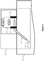
- FIG. 2A shows an example wake-up battery for a biosensor.
- the biosensor 200 is a glucose sensor, but in other examples the biosensor 200 may be a suitable sensor that is inserted into a patient's skin or other tissue, such as a blood oxygen sensor.
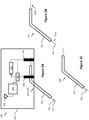
- the biosensor 200 includes a sensor element 210, which is shown in isolation in Figure 2B .
- the sensor element 210 includes an electrode 212 and a counter electrode 214.
- the counter electrode 214 is applied to the electrode 212 as a coating or sheath that partially covers the electrode 212, while leaving a portion of both the distal and proximal ends 212a-b of the electrode 212 exposed.
- the sensor also includes two conductive contacts 222-224 that are each connected to one of the electrode 212 or the counter electrode 214.
- the biosensor 200 also includes a battery 220, a wake-up circuit 240, a transmitter 250, and an antenna 252.
- the negative or ground terminal of the battery 220 is connected to one of the conductive contacts 224 and is the positive terminal of the battery 220 is selectively connected to the other conductive contact 222.
- the conductive contacts 222-224 are conductive rubber contacts, but in other examples, other suitable conductive materials, such as conductive metals, may be used.
- the wake-up circuit 240 is connected to both conductive contacts 222-224 and to the positive terminal of the battery 220.
- the wake-up circuit 240 can selectively connect the positive terminal of the battery 220 to the corresponding conductive contact 222.
- the wake-up circuit 240 can also selectively connect the positive terminal of the battery 220 to the transmitter 250.
- the transmitter can provide sensor data to a remote device by transmitting the data using the antenna 252.
- the transmitter 250 and antenna 252 can communicate using suitable communication techniques, such as radio frequency identification (“RFID”), near-field communication (“NFC”), or BlueToothTM.
- RFID radio frequency identification
- NFC near-field communication
- BlueToothTM BlueToothTM
- the electrode 212 and counter electrode 214 are each connected to a different conductive contact 222-224, and during operation can receive a voltage applied to the conductive contacts 222-224 and supply a current to the conductive contacts 222-224 based on reactions occurring in the patient's interstitial fluid.
- the electrode 212 is a platinum wire, though in some examples, the electrode 212 may be a platinum-coated wire.
- a platinum coating may be applied to a base wire by any suitable technique, including electroplating or physical vapor deposition, including evaporation and sputtering techniques. While a platinum material for a wire or coating for a wire may be suitable for a glucose sensor, other materials may be used according to other examples, based on the application or the desired reaction.
- the counter electrode 214 in this example is a silver/silver-chloride (Ag/AgCl) coating that is applied to the electrode 212.
- any suitable coating or sheath may be deposited, sintered, overlaid, or otherwise applied to the electrode to provide a counter electrode 214.
- a silver/silver-chloride material may be suitable for a glucose sensor, other materials may be used according to other examples, based on the application or the desired reaction.
- the counter electrode 214 may be physically separate from the electrode 212.
- Figure 3 shows an example sensor 300 having a counter electrode 312 physically separate from the electrode 310.
- the counter electrode 312 includes a second wire that can be separately inserted through a patient's skin and into the patient's interstitial fluid.
- the biosensor 200 also includes a second battery 230, shown in Figure 2C .
- the second battery 230 has two components, that when immersed in an electrolytic fluid, generate a current.
- the first component of the second battery 230 is an anode material 232 deposited on the electrode 212.
- the second component of the second battery 230 is the counter electrode 214 of the sensor element 210.
- the anode material 232 is deposited on the end of the electrode 212 that is inserted into the patient's interstitial fluid, referred to as the "distal" end 212a, thus allowing the anode material 232 to be immersed in the interstitial fluid, which is an electrolytic fluid.
- the anode material 232 is zinc, however, other suitable materials may be used, such as iron, aluminum, or nickel.
- the amount of anode material that is deposited on the electrode can depend on the amount of power needed to "wake-up" the biosensor 200.
- the biosensor 200 shown in Figure 2 has approximately 10 ng of zinc as the anode material 232, which should provide approximately 100 nanoamps ("nA") or 0.6 to 0.8 volts for approximately five minutes; however, up to approximately 100 ng of zinc may be applied, which should provide approximately 100 nA or 0.6 to 0.8 volts for approximately 50 minutes.
- suitable amounts of the anode material may also be between approximately 10-100 ng.
- suitable amounts of aluminum may be approximately 30 percent of the amount of zinc, e.g., between approximately 3-30 ng.
- Such amounts of anode material 232 should generate similar amounts of current and voltage for similar amounts of time as discussed above with respect to zinc.
- Selection of the amount of anode material 232 can be based on power requirements to "wake-up" other circuitry in the biosensor 200 as well as a desired amount of time during which to provide the power from the second battery 230.
- the sensor element 210 when active, also generates a current; however, in this example, this current is used to determine an amount of glucose present in the interstitial fluid. If the second battery 230 is generating current concurrently with the sensor element 210, the biosensor 200 may not be able provide reliable glucose level information. Thus, the amount of anode material 232 can be selected to minimize the life of the second battery 230, while still providing sufficient current to wake up the biosensor 200. As discussed above, in this example, the second battery 230 will provide current for approximately five minutes; however, other examples may require more time or power to wake up the biosensor 200.
- the wake-up circuit 240 is connected to each of the conductive contacts 222-224. While the second battery 230 is generating a current, the wake-up circuit 240 receives the current via the conductive contacts 222-224, e.g., from the second battery 230, and, when activated by the second battery 230, it connects the battery 220 to the conductive contact 224 via a potentiostat, which is incorporated into the wake-up circuit 240, and to the RF transmitter 250. The potentiostat will then provide a voltage to the sensor element 210, which will begin sensing an amount of glucose present in the patient's interstitial fluid in this example.
- FIG. 4 shows an example wake-up circuit 400.
- the wake-up circuit 400 is shown as a combination of a detector 410 and an activator 420; however, this should not be read to require that the wake-up circuit requires separate detection and activation components.
- the detector 410 receives an input signal from the wake-up battery, e.g., wake-up battery 230.
- the input signal may be a current or a voltage in various examples.
- the detector 410 receives the input signal and determines whether the input signal indicates that the wake-up battery has been activated.
- the detector 410 determines that the wake-up battery has been activated, it transmits a signal to the activator 420, which connects the battery 220 to the sensor element 210 via a potentiostat and, in some examples, activates other components or processing.
- the detector 410 includes a voltage threshold detector 500, shown in Figure 5 .
- the voltage threshold detector 500 includes a comparator circuit 510 that accepts a reference voltage 512 from the battery 220 and a sensed voltage 514 from the second battery 230. If the sensed voltage exceeds the reference voltage, the comparator circuit 510 outputs via output terminal 516 a non-zero voltage, otherwise the comparator circuit 510 outputs zero volts.
- the activator 420 in this example includes a transistor. The output of the comparator circuit 510 is connected to the transistor and turns the transistor on, connecting the battery 220 to the sensing element 210 via a potentiostat, and to the transmitter 250. In addition, the transistor's output is coupled to its own input so that, once the transistor is turned on, it remains on, even after the second battery 230 dies.
- Figure 6 shows another example wake-up circuit 600 which includes voltage controlled switch 610 that selectively connects a wake-up line 616 to ground 614 based on an input voltage 612 from a wake-up battery.
- the wake-up line 616 is inverted such that before the switch 610 is closed, the wake-up line 616 is held high by the second battery, but when the switch 610 closes, the wake-up line 616 is pulled low, thereby activating circuitry on the sensor, such as a processor or RF transmitter.
- the switch 610 in this example is shown as a voltage-controlled switch, any suitable switch may be employed.
- the wake-up circuit may include different types of circuits.
- the wake-up circuit may include a current threshold detector, a ring oscillator, a power-on-reset circuit, or an NMOS footer switch.
- the activator 420 may include a DC-DC converter, a clock circuit, or a processor.
- the detector 410 may output a signal to turn on a DC-DC converter that connects a battery to a sensor element.
- the detector 410 may output a signal that is provided as a signal to a processor or to a clock circuit.
- the processor may power on based on a power-on-reset signal and draw power from the battery 220 and supply a voltage to the sensor element.
- a clock circuit of the wake-up circuit such as a ring oscillator, may be used to generate a clock signal for another circuit, such as a processor clock to activate the processor, which begins drawing power from the battery 220.
- An NMOS footer switch may close to supply power from the battery 220 to a processor or another circuit to activate the sensing element.
- Figure 7 shows an example system that includes the glucose sensor 200 of Figure 2 , which is attached to a patient and the sensor element 210 has been inserted into the patient's skin, though other suitable biosensors may be used in example systems according to this disclosure, such as those shown in Figures 1 and 3 .
- the system also includes a computing device 700 that can receive sensor information from the glucose sensor 200 when it is in range of the sensor's RF transmitter 250.
- the computing device 700 includes a processor 710 and a memory 720, which are used by the computing device 700 to execute software for obtaining information from the glucose sensor 700 and store such information in the memory 720.
- the display 720 can provide a user interface and can provide sensor information that has been obtained from the glucose sensor 200.
- the computing device 700 also includes a radio transceiver 730 and antenna 732.
- the radio transceiver 730 is an RFID transceiver that emits RF signals to the glucose sensor 200, which then transmits sensor information to the computing device.
- suitable computing devices 700 may have other types of radio receivers or transceivers, such as an NFC transceiver, a BlueToothTM transceiver, or a wireless local area network (“WLAN”) transceiver, such as a WiFi transceiver. Selection of the appropriate transceiver may depend on the type transmitter 250 within the sensor 200.
- radio receivers or transceivers such as an NFC transceiver, a BlueToothTM transceiver, or a wireless local area network (“WLAN”) transceiver, such as a WiFi transceiver. Selection of the appropriate transceiver may depend on the type transmitter 250 within the sensor 200.
- Figure 8 shows a method of manufacturing a biosensor with a wake-up battery.
- an electrode and a counter electrode are provided.
- the electrode may be a platinum or platinum coated wire.
- the counter electrode may be a Ag/AgCl.
- a platinum layer may be applied to base wire by a suitable technique, including electroplating or physical vapor deposition, including evaporation and sputtering techniques.
- a counter electrode material, such as Ag/AgCl may be deposited or formed over a portion of the electrode.
- the counter electrode material may be deposited, sintered, overlaid, or otherwise applied to the electrode.
- the counter electrode may be formed separately from the electrode.
- an Ag/AgCl wire or Ag/AgCl coated wire may be employed as a counter-electrode.
- an anode material is applied near or at one end of the electrode.
- the anode material is zinc; however, other suitable materials may be used, such as iron, aluminum, or nickel.
- the amount of anode material that is deposited on the electrode can depend on the amount of power needed to "wake-up" the biosensor 200.
- a suitable amount of anode material may be 10-100 ng for a zinc, iron, or nickel anode material, while a suitable amount of aluminum may be 3-30 ng.
- the electrode and counter electrode are coupled to a potentiostat within the wake-up circuit. Examples of suitable wake-up circuits are discussed above with respect to figures 4-6 . In this example, the electrode and counter electrode are coupled to a V sense input of the wake-up circuit.
- the wake-up circuit is coupled to the battery.
- the wake-up circuit is coupled to the battery by a resistor that is selectably-coupled to a voltage-controlled switch.
- the voltage-controlled switch is initially set to an open position, but that when the wake-up circuit is activated, the wake-up circuit closes the switch to provide a wake-up signal to a processor.
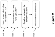
- Figure 9 shows a method of using a biosensor with a wake-up battery.
- the method of Figure 9 will be described with respect to the example glucose sensor 200 shown in Figure 2 ; however, the method is not limited to such a glucose sensor 200. Rather, the method may be performed with any suitable biosensor with a wake-up battery according to this disclosure.
- the biosensor's electrode 212 and counter-electrode 214 are inserted into the patient's skin and exposed to the patient's interstitial fluid.
- the anode material 232 of the wake-up battery 230 is immersed in the interstitial fluid.
- the anode material 232 and the counter electrode 214 upon immersion in the patient's interstitial fluid, activate the wake-up battery 230.
- the wake-up battery generates a voltage and a current which are transmitted to the wake-up circuit 240 after being immersed in the interstitial fluid.
- the wake-up circuit 240 in response to receiving the voltage and current from the wake-up battery 230, couples the battery 220 to the electrode 212 and the counter electrode 214 via a potentiostat to trigger a GOX/glucose reaction in the patient's interstitial fluid.
- the wireless transmitter 250 may transmit sensor information irrespective of the presence of a remote device, but in some examples, the wireless transmitter 250 may transmit sensor information in response to the presence of an RFID or NFC signal.
- references herein to an example or implementation means that a particular feature, structure, operation, or other characteristic described in connection with the example may be included in at least one implementation of the disclosure.
- the disclosure is not restricted to the particular examples or implementations described as such.
- the appearance of the phrases "in one example,” “in an example,” “in one implementation,” or “in an implementation,” or variations of the same in various places in the specification does not necessarily refer to the same example or implementation.
- Any particular feature, structure, operation, or other characteristic described in this specification in relation to one example or implementation may be combined with other features, structures, operations, or other characteristics described in respect of any other example or implementation.
- Some example biosensors with wake-up batteries may include a processor.
- the biosensor may include a computer-readable medium, such as a random access memory (RAM) coupled to the processor.
- the processor can execute computer-executable program instructions stored in memory, such as executing one or more computer programs.
- Such processors may comprise a microprocessor, a digital signal processor (DSP), an application-specific integrated circuit (ASIC), field programmable gate arrays (FPGAs), and state machines.
- Such processors may further comprise programmable electronic devices such as PLCs, programmable interrupt controllers (PICs), programmable logic devices (PLDs), programmable read-only memories (PROMs), electronically programmable read-only memories (EPROMs or EEPROMs), or other similar devices.
- PLCs programmable interrupt controllers
- PLDs programmable logic devices
- PROMs programmable read-only memories
- EPROMs or EEPROMs electronically programmable read-only memories
- Such processors may comprise, or may be in communication with, media, for example computer-readable storage media, that may store instructions that, when executed by the processor, can cause the processor to perform the steps described herein as carried out, or assisted, by a processor.
- Examples of computer-readable media may include, but are not limited to a memory chip, ROM, RAM, ASIC, or any other medium from which a computer processor can read or write information.
- the processor, and the processing, described may be in one or more structures, and may be dispersed through one or more structures.
- the processor may comprise code for carrying out one or more of the methods (or parts of methods) described herein.
- a or B or C includes any or all of the following alternative combinations as appropriate for a particular usage: A alone; B alone; C alone; A and B only; A and C only; B and C only; and all three of A and B and C.
Landscapes
- Health & Medical Sciences (AREA)
- Life Sciences & Earth Sciences (AREA)
- Physics & Mathematics (AREA)
- Engineering & Computer Science (AREA)
- Chemical & Material Sciences (AREA)
- Chemical Kinetics & Catalysis (AREA)
- Molecular Biology (AREA)
- General Chemical & Material Sciences (AREA)
- Surgery (AREA)
- Pathology (AREA)
- General Health & Medical Sciences (AREA)
- Electrochemistry (AREA)
- Biomedical Technology (AREA)
- Medical Informatics (AREA)
- Public Health (AREA)
- Veterinary Medicine (AREA)
- Heart & Thoracic Surgery (AREA)
- Animal Behavior & Ethology (AREA)
- Biophysics (AREA)
- Optics & Photonics (AREA)
- Manufacturing & Machinery (AREA)
- Sustainable Energy (AREA)
- Sustainable Development (AREA)
- Emergency Medicine (AREA)
- Oral & Maxillofacial Surgery (AREA)
- Computer Networks & Wireless Communication (AREA)
- Electromagnetism (AREA)
- Nuclear Medicine, Radiotherapy & Molecular Imaging (AREA)
- Spectroscopy & Molecular Physics (AREA)
- Analytical Chemistry (AREA)
- Biochemistry (AREA)
- General Physics & Mathematics (AREA)
- Immunology (AREA)
- Measurement Of The Respiration, Hearing Ability, Form, And Blood Characteristics Of Living Organisms (AREA)
- Electric Clocks (AREA)
- Radar Systems Or Details Thereof (AREA)
Description
- The present disclosure generally relates to invasive biosensors and more specifically to wake-up batteries for invasive biosensors.
- Invasive biosensors, such as implantable glucose sensors, may use a battery to power sensor components or other circuits or electronics to obtain information from the sensor components and to transmit the information to another device. However, while the biosensor sits idle, e.g., in a package on a shelf, its battery may slowly discharge over time before the sensor is used, thereby reducing the useful life of the sensor.
-
US 2010/213082 A relates to a self-powered analyte determining device including a working electrode, a counter electrode and an optional resistance value, where the working electrode includes analyte sensing components and the self-powered analyte determining device spontaneously passes a current directly proportional to analyte concentration in the absence of an external power source. -
US 2008/284599 A discloses compositions, systems and methods that allow for the detection of physical delivery of a pharmaceutical agent to a body. -
US 2004/066262 A describes a system and method to delay closure of an electrical circuit of a battery-powered electrical device, intended to operate remotely in an environment in which the pH value changes from one value to another. In one example, two electrical contacts of an electrical circuit are separated by an insulator that holds the circuit open until the device is exposed to an environment having a predetermined pH value, which causes the insulator to dissolve and the circuit to close, energizing the device. - The present invention provides a device as defined in claim 1 and a method as defined in claim 6. Preferred embodiments of the invention are defined in the dependent claims.
- The device according to the present invention includes a biosensor comprising a first electrode having a distal end for insertion into a subcutaneous layer beneath a patient's skin, a second electrode coupled to the first electrode, a portion of the second electrode for insertion into the subcutaneous layer, and a first battery to apply a voltage across the first and second electrodes, the first battery at least partially electrically decoupled from the electrodes; a second battery comprising an anode material coupled to a portion of the distal end of the first electrode, the anode material for insertion into the subcutaneous layer, and a portion of the second electrode, the second battery activatable upon immersion in an electrolytic fluid; and a wake-up circuit coupled to the second battery to receive a signal from the second battery and, in response, to electrically couple the first battery to the first and second electrodes.
- In addition, various examples are described for wake-up batteries for invasive biosensors. One disclosed method includes inserting an insertable portion of a biosensor and a second battery into a patient's skin and into the patient's interstitial fluid, the insertable portion comprising: a distal end of a first electrode and a portion of second electrode, the first electrode coupled to the second electrode, the biosensor further comprising a first battery to apply a voltage across the first and second electrodes, the first battery at least partially electrically decoupled from the electrodes, the second battery comprising an anode material coupled to a portion of the distal end of the first electrode and a portion of the second electrode; generating a signal by the second battery after the second battery is immersed in the patient's interstitial fluid; electrically coupling the first battery to the first and second electrodes by a wake-up circuit in response to receiving the signal from the second battery; and providing sensor information from the biosensor to a radio frequency ("RF") transmitter.
- Another disclosed device includes a biosensor comprising: a first electrode having a distal end for insertion into a subcutaneous layer beneath a patient's skin, and a second electrode coupled to the first electrode, a portion of the second electrode for insertion into the subcutaneous layer, and a first battery comprising: an anode material coupled to a portion of the distal end of the first electrode, the anode material for insertion into the subcutaneous layer, and a portion of the second electrode, the first battery activatable upon immersion in an electrolytic fluid to apply a voltage to the first and second electrodes.
- A further disclosed method includes inserting an insertable portion of a biosensor and a second battery into a patient's skin and into the patient's interstitial fluid, the insertable portion comprising: a distal end of a first electrode and a portion of second electrode, the first electrode coupled to the second electrode, the biosensor further comprising a first battery to apply a voltage across the first and second electrodes, the first battery at least partially electrically decoupled from the electrodes, the second battery comprising an anode material coupled to a portion of the distal end of the first electrode and a portion of the second electrode; generating a signal by the second battery after the second battery is immersed in the patient's interstitial fluid; electrically coupling the first battery to the first and second electrodes by a wake-up circuit in response to receiving the signal from the second battery; and providing sensor information from the biosensor to a radio frequency ("RF") transmitter.
- These illustrative examples are mentioned not to limit or define the scope of this disclosure, but rather to provide examples to aid understanding thereof. Illustrative examples are discussed in the Detailed Description, which provides further description. Advantages offered by various examples may be further understood by examining this specification.
- The accompanying drawings, which are incorporated into and constitute a part of this specification, illustrate one or more certain examples and, together with the description of the example, serve to explain the principles and implementations of the certain examples.
-
Figure 1 shows an illustrative example glucose sensor with a wake-up battery; -
Figures 2A-3 show example biosensors with wake-up batteries; -
Figures 4-6 show example wake-up circuits suitable for use with example biosensors with wake-up batteries; -
Figure 7 shows an example system for biosensors with wake-up batteries; -
Figure 8 shows an example method of manufacture of a biosensor with a wake-up battery; and -
Figure 9 shows an example method of use of a biosensor with a wake-up battery. - Examples are described herein in the context of wake-up batteries for invasive biosensors. Those of ordinary skill in the art will realize that the following description is illustrative only and is not intended to be in any way limiting. Reference will now be made in detail to implementations of examples as illustrated in the accompanying drawings. The same reference indicators will be used throughout the drawings and the following description to refer to the same or like items.
- In the interest of clarity, not all of the routine features of the examples described herein are shown and described. It will, of course, be appreciated that in the development of any such actual implementation, numerous implementation-specific decisions must be made in order to achieve the developer's specific goals, such as compliance with application- and business-related constraints, and that these specific goals will vary from one implementation to another and from one developer to another.
- One example invasive sensor shown in
Figure 1 is aglucose sensor 100. Thisexample glucose sensor 100 has twoelectrodes skin 102 to expose theelectrodes electrodes wire 110, and (2) a silver/silver-chloride (Ag/AgCl)material 112 that covers a part of thewire 110. One end of thewire 110 and a portion of the Ag/AgCl material 112 are inserted into the patient'sskin 102, while the other end of thewire 110 is attached to oneterminal 124 of abattery 120 and another portion of the Ag/AgCl material 112 is attached to theother terminal 122 of thebattery 120. - The portion of the
wire 110 that is inserted into the patient'sskin 102 also has a glucose oxidase ("GOX") coating that will react to glucose present within the patient's interstitial fluid. When thewire 110 and the invasive portion of the Ag/AgCl material 112 are inserted into the patient'sskin 102, the GOX reacts with glucose, which creates reaction products, such as hydrogen peroxide. When a voltage is applied to theelectrodes - However, an invasive sensor, such as this
example glucose sensor 100, may sit idle for an extended period of time, e.g., several months or more in storage, before it is used. If theglucose sensor 100 is not disabled while it is idle, thebattery 120 may drain, reducing or, if the battery drains entirely, eliminating the useful life of theglucose sensor 100. To reduce or eliminate premature discharge of thebattery 120, a second battery may be constructed from the glucose sensor components by affixing a small amount of ananode material 130, such as zinc, to the end of thewire 110 that is inserted into the patient'sskin 102. Theanode material 130 in conjunction with the Ag/AgCl material 112 and the patient's interstitial fluid creates a small battery that generates a current from the twoelectrodes glucose sensor 100. The current generated by this second battery is independent of any glucose/GOX reaction. The second battery, which may be referred to as a "wake-up" battery in this disclosure, therefore generates a current that can be used to enable or "wake-up" theglucose sensor 110 by activating acircuit 140 that connects thebattery 120 to the electrodes via, e.g., a potentiostat (not shown), such as by closing aswitch 142. It may also connect thebattery 120 to other circuits within theglucose sensor 100, such as a radio frequency ("RF") transmitter (not shown) to transmit glucose sensor readings. Once theglucose sensor 100 is enabled, themain battery 120 can supply the voltage to theelectrodes - However, because glucose sensor readings are based on currents generated by the two electrodes, the current generated by the wake-up battery may interfere with the glucose sensor readings. Thus, the wake-up battery is created by using only a small amount of the
anode material 130. For example, a suitable amount ofanode material 130 may be 10 nanograms ("ng") of zinc. As a result, the wake-up battery is able to supply enough electric current to activate the electronic circuitry powered by the first battery that enables theglucose sensor 100, but then quickly dies. Once the wake-up battery is dead, theglucose sensor 100 can provide reliable glucose information. - This illustrative example is given to introduce the reader to the general subject matter discussed herein and the disclosure is not limited to this example. The following sections describe various additional non-limiting examples and examples of systems and methods for wake-up batteries for invasive biosensors.
- Referring now to
Figures 2A-2B, Figure 2A shows an example wake-up battery for a biosensor. In this example, thebiosensor 200 is a glucose sensor, but in other examples thebiosensor 200 may be a suitable sensor that is inserted into a patient's skin or other tissue, such as a blood oxygen sensor. - The
biosensor 200 includes asensor element 210, which is shown in isolation inFigure 2B . Thesensor element 210 includes anelectrode 212 and acounter electrode 214. Thecounter electrode 214 is applied to theelectrode 212 as a coating or sheath that partially covers theelectrode 212, while leaving a portion of both the distal andproximal ends 212a-b of theelectrode 212 exposed. The sensor also includes two conductive contacts 222-224 that are each connected to one of theelectrode 212 or thecounter electrode 214. - The
biosensor 200 also includes abattery 220, a wake-up circuit 240, atransmitter 250, and anantenna 252. The negative or ground terminal of thebattery 220 is connected to one of theconductive contacts 224 and is the positive terminal of thebattery 220 is selectively connected to the otherconductive contact 222. In this example, the conductive contacts 222-224 are conductive rubber contacts, but in other examples, other suitable conductive materials, such as conductive metals, may be used. - The wake-
up circuit 240 is connected to both conductive contacts 222-224 and to the positive terminal of thebattery 220. The wake-up circuit 240 can selectively connect the positive terminal of thebattery 220 to the correspondingconductive contact 222. In addition, in this example, the wake-up circuit 240 can also selectively connect the positive terminal of thebattery 220 to thetransmitter 250. The transmitter can provide sensor data to a remote device by transmitting the data using theantenna 252. In some examples, thetransmitter 250 andantenna 252 can communicate using suitable communication techniques, such as radio frequency identification ("RFID"), near-field communication ("NFC"), or BlueTooth™. For example, a remote device with an RFID or NFC reader may be brought into proximity of theantenna 252 and cause thetransmitter 250 to transmit sensor information to the remote device. - The
electrode 212 andcounter electrode 214 are each connected to a different conductive contact 222-224, and during operation can receive a voltage applied to the conductive contacts 222-224 and supply a current to the conductive contacts 222-224 based on reactions occurring in the patient's interstitial fluid. - In this example, the
electrode 212 is a platinum wire, though in some examples, theelectrode 212 may be a platinum-coated wire. A platinum coating may be applied to a base wire by any suitable technique, including electroplating or physical vapor deposition, including evaporation and sputtering techniques. While a platinum material for a wire or coating for a wire may be suitable for a glucose sensor, other materials may be used according to other examples, based on the application or the desired reaction. - The
counter electrode 214 in this example is a silver/silver-chloride (Ag/AgCl) coating that is applied to theelectrode 212. However, any suitable coating or sheath may be deposited, sintered, overlaid, or otherwise applied to the electrode to provide acounter electrode 214. Further, while a silver/silver-chloride material may be suitable for a glucose sensor, other materials may be used according to other examples, based on the application or the desired reaction. - In some examples, the
counter electrode 214 may be physically separate from theelectrode 212.Figure 3 shows anexample sensor 300 having acounter electrode 312 physically separate from theelectrode 310. In this example, thecounter electrode 312 includes a second wire that can be separately inserted through a patient's skin and into the patient's interstitial fluid. - Referring again to
Figure 2A , thebiosensor 200 also includes asecond battery 230, shown inFigure 2C . Thesecond battery 230 has two components, that when immersed in an electrolytic fluid, generate a current. The first component of thesecond battery 230 is ananode material 232 deposited on theelectrode 212. The second component of thesecond battery 230 is thecounter electrode 214 of thesensor element 210. Theanode material 232 is deposited on the end of theelectrode 212 that is inserted into the patient's interstitial fluid, referred to as the "distal"end 212a, thus allowing theanode material 232 to be immersed in the interstitial fluid, which is an electrolytic fluid. - In this example, the
anode material 232 is zinc, however, other suitable materials may be used, such as iron, aluminum, or nickel. The amount of anode material that is deposited on the electrode can depend on the amount of power needed to "wake-up" thebiosensor 200. Thebiosensor 200 shown inFigure 2 has approximately 10 ng of zinc as theanode material 232, which should provide approximately 100 nanoamps ("nA") or 0.6 to 0.8 volts for approximately five minutes; however, up to approximately 100 ng of zinc may be applied, which should provide approximately 100 nA or 0.6 to 0.8 volts for approximately 50 minutes. For some other anode materials, such as iron and nickel, suitable amounts of the anode material may also be between approximately 10-100 ng. For asecond battery 230 constructed using aluminum, suitable amounts of aluminum may be approximately 30 percent of the amount of zinc, e.g., between approximately 3-30 ng. Such amounts ofanode material 232 should generate similar amounts of current and voltage for similar amounts of time as discussed above with respect to zinc. - Selection of the amount of
anode material 232 can be based on power requirements to "wake-up" other circuitry in thebiosensor 200 as well as a desired amount of time during which to provide the power from thesecond battery 230. Thesensor element 210, when active, also generates a current; however, in this example, this current is used to determine an amount of glucose present in the interstitial fluid. If thesecond battery 230 is generating current concurrently with thesensor element 210, thebiosensor 200 may not be able provide reliable glucose level information. Thus, the amount ofanode material 232 can be selected to minimize the life of thesecond battery 230, while still providing sufficient current to wake up thebiosensor 200. As discussed above, in this example, thesecond battery 230 will provide current for approximately five minutes; however, other examples may require more time or power to wake up thebiosensor 200. - As discussed above, the wake-
up circuit 240 is connected to each of the conductive contacts 222-224. While thesecond battery 230 is generating a current, the wake-up circuit 240 receives the current via the conductive contacts 222-224, e.g., from thesecond battery 230, and, when activated by thesecond battery 230, it connects thebattery 220 to theconductive contact 224 via a potentiostat, which is incorporated into the wake-up circuit 240, and to theRF transmitter 250. The potentiostat will then provide a voltage to thesensor element 210, which will begin sensing an amount of glucose present in the patient's interstitial fluid in this example. - Referring now to
Figure 4, Figure 4 shows an example wake-up circuit 400. The wake-up circuit 400 is shown as a combination of adetector 410 and anactivator 420; however, this should not be read to require that the wake-up circuit requires separate detection and activation components. Thedetector 410 receives an input signal from the wake-up battery, e.g., wake-upbattery 230. The input signal may be a current or a voltage in various examples. Thedetector 410 receives the input signal and determines whether the input signal indicates that the wake-up battery has been activated. If thedetector 410 determines that the wake-up battery has been activated, it transmits a signal to theactivator 420, which connects thebattery 220 to thesensor element 210 via a potentiostat and, in some examples, activates other components or processing. - In this example, the
detector 410 includes avoltage threshold detector 500, shown inFigure 5 . Thevoltage threshold detector 500 includes acomparator circuit 510 that accepts areference voltage 512 from thebattery 220 and a sensedvoltage 514 from thesecond battery 230. If the sensed voltage exceeds the reference voltage, thecomparator circuit 510 outputs via output terminal 516 a non-zero voltage, otherwise thecomparator circuit 510 outputs zero volts. Theactivator 420 in this example includes a transistor. The output of thecomparator circuit 510 is connected to the transistor and turns the transistor on, connecting thebattery 220 to thesensing element 210 via a potentiostat, and to thetransmitter 250. In addition, the transistor's output is coupled to its own input so that, once the transistor is turned on, it remains on, even after thesecond battery 230 dies. -
Figure 6 shows another example wake-up circuit 600 which includes voltage controlledswitch 610 that selectively connects a wake-upline 616 to ground 614 based on aninput voltage 612 from a wake-up battery. In this example, the wake-upline 616 is inverted such that before theswitch 610 is closed, the wake-upline 616 is held high by the second battery, but when theswitch 610 closes, the wake-upline 616 is pulled low, thereby activating circuitry on the sensor, such as a processor or RF transmitter. While theswitch 610 in this example is shown as a voltage-controlled switch, any suitable switch may be employed. - In some examples, the wake-up circuit may include different types of circuits. For example, the wake-up circuit may include a current threshold detector, a ring oscillator, a power-on-reset circuit, or an NMOS footer switch. In some examples, the
activator 420 may include a DC-DC converter, a clock circuit, or a processor. For example, thedetector 410 may output a signal to turn on a DC-DC converter that connects a battery to a sensor element. In some examples, thedetector 410 may output a signal that is provided as a signal to a processor or to a clock circuit. For example, the processor may power on based on a power-on-reset signal and draw power from thebattery 220 and supply a voltage to the sensor element. A clock circuit of the wake-up circuit, such as a ring oscillator, may be used to generate a clock signal for another circuit, such as a processor clock to activate the processor, which begins drawing power from thebattery 220. An NMOS footer switch may close to supply power from thebattery 220 to a processor or another circuit to activate the sensing element. - Referring now to
Figure 7, Figure 7 shows an example system that includes theglucose sensor 200 ofFigure 2 , which is attached to a patient and thesensor element 210 has been inserted into the patient's skin, though other suitable biosensors may be used in example systems according to this disclosure, such as those shown inFigures 1 and3 . The system also includes acomputing device 700 that can receive sensor information from theglucose sensor 200 when it is in range of the sensor'sRF transmitter 250. - The
computing device 700 includes aprocessor 710 and amemory 720, which are used by thecomputing device 700 to execute software for obtaining information from theglucose sensor 700 and store such information in thememory 720. Thedisplay 720 can provide a user interface and can provide sensor information that has been obtained from theglucose sensor 200. Thecomputing device 700 also includes aradio transceiver 730 andantenna 732. In this example, theradio transceiver 730 is an RFID transceiver that emits RF signals to theglucose sensor 200, which then transmits sensor information to the computing device. However, othersuitable computing devices 700 according to this disclosure may have other types of radio receivers or transceivers, such as an NFC transceiver, a BlueTooth™ transceiver, or a wireless local area network ("WLAN") transceiver, such as a WiFi transceiver. Selection of the appropriate transceiver may depend on thetype transmitter 250 within thesensor 200. - Referring now to
Figure 8, Figure 8 shows a method of manufacturing a biosensor with a wake-up battery. - At
block 810, an electrode and a counter electrode are provided. As discussed above, the electrode may be a platinum or platinum coated wire. The counter electrode may be a Ag/AgCl. In one example, a platinum layer may be applied to base wire by a suitable technique, including electroplating or physical vapor deposition, including evaporation and sputtering techniques. A counter electrode material, such as Ag/AgCl may be deposited or formed over a portion of the electrode. For example, the counter electrode material may be deposited, sintered, overlaid, or otherwise applied to the electrode. In some examples, the counter electrode may be formed separately from the electrode. For example, an Ag/AgCl wire or Ag/AgCl coated wire may be employed as a counter-electrode. - At
block 820, an anode material is applied near or at one end of the electrode. In this example, the anode material is zinc; however, other suitable materials may be used, such as iron, aluminum, or nickel. As discussed above, the amount of anode material that is deposited on the electrode can depend on the amount of power needed to "wake-up" thebiosensor 200. In some examples, a suitable amount of anode material may be 10-100 ng for a zinc, iron, or nickel anode material, while a suitable amount of aluminum may be 3-30 ng. - At
block 830, the electrode and counter electrode are coupled to a potentiostat within the wake-up circuit. Examples of suitable wake-up circuits are discussed above with respect tofigures 4-6 . In this example, the electrode and counter electrode are coupled to a Vsense input of the wake-up circuit. - At
block 840, the wake-up circuit is coupled to the battery. In this example, the wake-up circuit is coupled to the battery by a resistor that is selectably-coupled to a voltage-controlled switch. The voltage-controlled switch is initially set to an open position, but that when the wake-up circuit is activated, the wake-up circuit closes the switch to provide a wake-up signal to a processor. - Referring now to
Figure 9, Figure 9 shows a method of using a biosensor with a wake-up battery. The method ofFigure 9 will be described with respect to theexample glucose sensor 200 shown inFigure 2 ; however, the method is not limited to such aglucose sensor 200. Rather, the method may be performed with any suitable biosensor with a wake-up battery according to this disclosure. - At
block 910, the biosensor'selectrode 212 and counter-electrode 214 are inserted into the patient's skin and exposed to the patient's interstitial fluid. In addition, theanode material 232 of the wake-upbattery 230 is immersed in the interstitial fluid. Theanode material 232 and thecounter electrode 214, upon immersion in the patient's interstitial fluid, activate the wake-upbattery 230. - At
block 920, the wake-up battery generates a voltage and a current which are transmitted to the wake-up circuit 240 after being immersed in the interstitial fluid. - At
block 930, the wake-up circuit 240, in response to receiving the voltage and current from the wake-upbattery 230, couples thebattery 220 to theelectrode 212 and thecounter electrode 214 via a potentiostat to trigger a GOX/glucose reaction in the patient's interstitial fluid. - At
block 940, current generated by the GOX/glucose reaction is sensed and the sensed current level is transmitted by thewireless transmitter 250 andantenna 252. In one example, thewireless transmitter 250 may transmit sensor information irrespective of the presence of a remote device, but in some examples, thewireless transmitter 250 may transmit sensor information in response to the presence of an RFID or NFC signal. - The foregoing description of some examples has been presented only for the purpose of illustration and description and is not intended to be exhaustive or to limit the disclosure to the precise forms disclosed. Numerous modifications and adaptations thereof will be apparent to those skilled in the art without departing from the spirit and scope of the disclosure.
- Reference herein to an example or implementation means that a particular feature, structure, operation, or other characteristic described in connection with the example may be included in at least one implementation of the disclosure. The disclosure is not restricted to the particular examples or implementations described as such. The appearance of the phrases "in one example," "in an example," "in one implementation," or "in an implementation," or variations of the same in various places in the specification does not necessarily refer to the same example or implementation. Any particular feature, structure, operation, or other characteristic described in this specification in relation to one example or implementation may be combined with other features, structures, operations, or other characteristics described in respect of any other example or implementation.
- Some example biosensors with wake-up batteries according to this disclosure may include a processor. The biosensor may include a computer-readable medium, such as a random access memory (RAM) coupled to the processor. The processor can execute computer-executable program instructions stored in memory, such as executing one or more computer programs. Such processors may comprise a microprocessor, a digital signal processor (DSP), an application-specific integrated circuit (ASIC), field programmable gate arrays (FPGAs), and state machines. Such processors may further comprise programmable electronic devices such as PLCs, programmable interrupt controllers (PICs), programmable logic devices (PLDs), programmable read-only memories (PROMs), electronically programmable read-only memories (EPROMs or EEPROMs), or other similar devices.
- Such processors may comprise, or may be in communication with, media, for example computer-readable storage media, that may store instructions that, when executed by the processor, can cause the processor to perform the steps described herein as carried out, or assisted, by a processor. Examples of computer-readable media may include, but are not limited to a memory chip, ROM, RAM, ASIC, or any other medium from which a computer processor can read or write information. The processor, and the processing, described may be in one or more structures, and may be dispersed through one or more structures. The processor may comprise code for carrying out one or more of the methods (or parts of methods) described herein.
- Use herein of the word "or" is intended to cover inclusive and exclusive OR conditions. In other words, A or B or C includes any or all of the following alternative combinations as appropriate for a particular usage: A alone; B alone; C alone; A and B only; A and C only; B and C only; and all three of A and B and C.
Claims (13)
- A device comprising:a biosensor (100, 200, 300) comprising:a first electrode (110, 210, 310) having a distal end for insertion into a subcutaneous layer beneath a patient's skin,a second electrode (112, 212, 312) coupled to the first electrode (110, 210, 310), a portion of the second electrode for insertion into the subcutaneous layer, anda first battery (120, 220) to apply a voltage across the first and second electrodes, the first battery (120, 220) at least partially electrically decoupled from the electrodes;a second battery comprising:an anode material (130, 232) coupled to a portion of the distal end of the first electrode (110, 210, 310), the anode material (130, 232) for insertion into the subcutaneous layer, and
a portion of the second electrode,the second battery activatable upon immersion in an electrolytic fluid; anda wake-up circuit (140, 240, 400) coupled to the second battery to receive a signal from the second battery and, in response, to electrically couple the first battery to the first and second electrodes. - The device of claim 1, further comprising a glucose oxidase material disposed on a portion of the distal end of the first electrode (110, 210, 310).
- The device of claim 1, further comprising a radio frequency ("RF") transmitter, and wherein:the first battery (120, 220) is at least partially electrically decoupled from the RF transmitter and is further to apply power to the RF transmitter, andthe wake-up circuit (140, 240, 400) is further to electrically couple the first battery (120, 220) to the RF transmitter in response to receiving the signal from the second battery.
- The device of claim 1 , wherein:the first electrode (110, 210, 310) comprises a platinum material;the second electrode (112, 212, 312) comprises a silver/silver-chloride material coating a portion of the first electrode (110, 210, 310); andthe anode material (130, 232) comprises zinc, iron, aluminum, or nickel.
- The device of claim 1 , wherein the anode material (130, 232) comprises approximately 10 to 100 nanograms ("ng") of zinc, approximately 10 to 100 ng of nickel, approximately 10 to 100 ng of iron, or approximately 3 to 30 ng of aluminum.
- A method comprising:providing first and second electrodes, the first electrode (110, 210, 310) having a distal end for insertion into a subcutaneous layer beneath a patient's skin, the second electrode (112, 212, 312) coupled to the first electrode (110, 210, 310), a portion of the second electrode (112, 212, 312) for insertion into the subcutaneous layer;applying an anode material (130, 232) proximate to the distal end of the first electrode (110, 210, 310);coupling a wake-up circuit (140, 240, 400) to the first and second electrodes to receive a signal from a second battery in response to immersion of the second battery in an electrolytic fluid, the second battery comprising the anode material (130, 232) and the second electrode (112, 212, 312); andcoupling a first battery (120, 220) to the wake-up circuit, the wake-up circuit to electrically couple the first battery (120, 220) to the first and second electrodes in response to the signal from the second battery.
- The method of claim 6, further comprising a glucose oxidase material disposed on a portion of the distal end of the first electrode (110, 210, 310).
- The method of claim 6, further comprising coupling a radio frequency ("RF") transmitter to the wake-up circuit (140, 240, 400), and wherein:the first battery (120, 220) is at least partially electrically decoupled from the RF transmitter and is further to apply power to the RF transmitter, andthe wake-up circuit (140, 240, 400) is further to electrically couple the first battery (120, 220) to the RF transmitter in response to receiving the signal from the second battery.
- The method of claim 6, wherein:the first electrode (110, 210, 310) comprises a platinum material;the second electrode (112, 212, 312) comprises a silver/silver-chloride material coating a portion of the first electrode (110, 210, 310); andthe anode material (130, 232) comprises zinc, iron, aluminum, or nickel.
- The method of claim 6, wherein the anode material (130, 232) comprises approximately 10 to 100 nanograms ("ng") of zinc, approximately 10 to 100 ng of nickel, approximately 10 to 100 ng of iron, or approximately 3 to 30 ng of aluminum.
- The device of claim 1 or the method of claim 6, wherein the wake-up circuit (140, 240, 400) comprises one or more of (1) a voltage threshold detection circuit (500) and a reference voltage source, (2) a current threshold detection circuit and a reference current source, (3) a ring oscillator, (4) a power-on reset circuit, or (5) an NMOS footer switch.
- The device of claim 1 or the method of claim 6, wherein the biosensor (100, 200, 300) further comprises a processor, and wherein the wake-up circuit (140, 240, 400) is further to electrically couple the first battery (120, 220) to the processor.
- The device or method of claim 12, wherein the wake-up circuit (140, 240, 400) comprises a ring oscillator electrically coupled to a clock circuit of the processor to activate the clock circuit after receiving the signal from the second battery.
Applications Claiming Priority (2)
| Application Number | Priority Date | Filing Date | Title |
|---|---|---|---|
| US15/232,296 US11026609B2 (en) | 2016-08-09 | 2016-08-09 | Wake-up batteries for invasive biosensors |
| PCT/US2017/042052 WO2018031183A1 (en) | 2016-08-09 | 2017-07-14 | Wake-up batteries for invasive biosensors |
Publications (2)
| Publication Number | Publication Date |
|---|---|
| EP3496612A1 EP3496612A1 (en) | 2019-06-19 |
| EP3496612B1 true EP3496612B1 (en) | 2020-12-23 |
Family
ID=59409765
Family Applications (1)
| Application Number | Title | Priority Date | Filing Date |
|---|---|---|---|
| EP17745228.1A Active EP3496612B1 (en) | 2016-08-09 | 2017-07-14 | Wake-up batteries for invasive biosensors |
Country Status (5)
| Country | Link |
|---|---|
| US (2) | US11026609B2 (en) |
| EP (1) | EP3496612B1 (en) |
| CN (1) | CN109561861B (en) |
| TW (1) | TWI775765B (en) |
| WO (1) | WO2018031183A1 (en) |
Families Citing this family (8)
| Publication number | Priority date | Publication date | Assignee | Title |
|---|---|---|---|---|
| US11026609B2 (en) * | 2016-08-09 | 2021-06-08 | Verily Life Sciences Llc | Wake-up batteries for invasive biosensors |
| CN113885409B (en) * | 2021-11-05 | 2024-12-10 | 苏州中星医疗技术有限公司 | Circuit system and method for waking up transmitter |
| US20230389829A1 (en) * | 2022-06-03 | 2023-12-07 | Azoteq Holdings Limited | Wake-up circuit |
| KR102777847B1 (en) | 2023-01-31 | 2025-03-10 | 쓰리에이로직스(주) | Portable nfc device that releases reset in response to radio frequency signal, and nfc tag circuit included therein |
| KR102777789B1 (en) | 2023-01-31 | 2025-03-10 | 쓰리에이로직스(주) | Nfc device powered on in response to radio frequency signal, nfc tag circuit included therein, and method of operating the nfc device |
| KR102806069B1 (en) | 2023-03-31 | 2025-05-14 | 쓰리에이로직스(주) | Electronic device powered on in response to radio frequency signal, nfc tag circuit included therein, and method of operating the same |
| KR20250097559A (en) | 2023-12-21 | 2025-06-30 | 쓰리에이로직스(주) | Sensing device capable of ensuring reliability of sensing data, and method of operating the same |
| WO2025216456A1 (en) * | 2024-04-09 | 2025-10-16 | 아나세닉스 주식회사 | Implantable continuous blood glucose measurement device and system |
Family Cites Families (16)
| Publication number | Priority date | Publication date | Assignee | Title |
|---|---|---|---|---|
| US3837339A (en) * | 1972-02-03 | 1974-09-24 | Whittaker Corp | Blood glucose level monitoring-alarm system and method therefor |
| EP0363504A1 (en) * | 1988-10-10 | 1990-04-18 | Dräger Nederland B.V. | Method of providing a substrate with a layer comprising a polyvinylbased hydrogel and a biochemically active material |
| US6217744B1 (en) | 1998-12-18 | 2001-04-17 | Peter Crosby | Devices for testing fluid |
| US6666821B2 (en) * | 2001-01-08 | 2003-12-23 | Medtronic, Inc. | Sensor system |
| US6846994B2 (en) | 2001-09-19 | 2005-01-25 | Justin B. Wenner | System and method to delay closure of a normally closed electrical circuit |
| US7381184B2 (en) * | 2002-11-05 | 2008-06-03 | Abbott Diabetes Care Inc. | Sensor inserter assembly |
| US6903616B2 (en) * | 2003-06-24 | 2005-06-07 | Stmicroelectronics, Inc. | Startup circuit and method for starting an oscillator after power-off |
| CA2789262C (en) * | 2005-04-28 | 2016-10-04 | Proteus Digital Health, Inc. | Pharma-informatics system |
| US8912908B2 (en) * | 2005-04-28 | 2014-12-16 | Proteus Digital Health, Inc. | Communication system with remote activation |
| KR100896234B1 (en) * | 2007-08-10 | 2009-05-08 | 주식회사 아이센스 | Electrochemical Biosensors and Measuring Instruments |
| US9402544B2 (en) * | 2009-02-03 | 2016-08-02 | Abbott Diabetes Care Inc. | Analyte sensor and apparatus for insertion of the sensor |
| US20100213057A1 (en) * | 2009-02-26 | 2010-08-26 | Benjamin Feldman | Self-Powered Analyte Sensor |
| US11363951B2 (en) * | 2011-09-13 | 2022-06-21 | Glaukos Corporation | Intraocular physiological sensor |
| US9693714B2 (en) | 2012-02-10 | 2017-07-04 | Senseonics, Incorporated | Digital ASIC sensor platform |
| TW201526867A (en) | 2013-12-05 | 2015-07-16 | Dexing Pang | Implantable biosensor |
| US11026609B2 (en) * | 2016-08-09 | 2021-06-08 | Verily Life Sciences Llc | Wake-up batteries for invasive biosensors |
-
2016
- 2016-08-09 US US15/232,296 patent/US11026609B2/en active Active
-
2017
- 2017-07-14 EP EP17745228.1A patent/EP3496612B1/en active Active
- 2017-07-14 CN CN201780048817.8A patent/CN109561861B/en active Active
- 2017-07-14 WO PCT/US2017/042052 patent/WO2018031183A1/en not_active Ceased
- 2017-08-07 TW TW106126504A patent/TWI775765B/en active
-
2021
- 2021-05-27 US US17/332,048 patent/US12336818B2/en active Active
Non-Patent Citations (1)
| Title |
|---|
| None * |
Also Published As
| Publication number | Publication date |
|---|---|
| CN109561861A (en) | 2019-04-02 |
| TWI775765B (en) | 2022-09-01 |
| CN109561861B (en) | 2022-11-04 |
| US20210369156A1 (en) | 2021-12-02 |
| WO2018031183A1 (en) | 2018-02-15 |
| US11026609B2 (en) | 2021-06-08 |
| US12336818B2 (en) | 2025-06-24 |
| US20180042538A1 (en) | 2018-02-15 |
| EP3496612A1 (en) | 2019-06-19 |
| TW201822714A (en) | 2018-07-01 |
Similar Documents
| Publication | Publication Date | Title |
|---|---|---|
| US12336818B2 (en) | Wake-up batteries for invasive biosensors | |
| US20220330856A1 (en) | Analyte monitoring devices and methods | |
| CN105899132B (en) | Self-powered analyte sensors and devices using the same | |
| JP5795584B2 (en) | Medical device | |
| CN102348414B (en) | Method for Continuous Measurement of Substrate Concentration | |
| US10361574B2 (en) | Systems, devices, and methods for control of a power supply connection | |
| US10154805B2 (en) | Disposable glucose biosensor including an activity sensor | |
| EP3733064B1 (en) | Continuous analyte sensor with magnetic activation | |
| JP2013502978A5 (en) | ||
| US9442089B2 (en) | Analyte meter test strip detection | |
| JP2025503420A (en) | Analyte Sensor Deployment Testing | |
| US12408868B1 (en) | Systems and methods for peel-off detection for low-power electronics | |
| WO2024061018A1 (en) | Sensitivity determination method, implantation effect judgment method, and related apparatus |
Legal Events
| Date | Code | Title | Description |
|---|---|---|---|
| STAA | Information on the status of an ep patent application or granted ep patent |
Free format text: STATUS: UNKNOWN |
|
| STAA | Information on the status of an ep patent application or granted ep patent |
Free format text: STATUS: THE INTERNATIONAL PUBLICATION HAS BEEN MADE |
|
| PUAI | Public reference made under article 153(3) epc to a published international application that has entered the european phase |
Free format text: ORIGINAL CODE: 0009012 |
|
| STAA | Information on the status of an ep patent application or granted ep patent |
Free format text: STATUS: REQUEST FOR EXAMINATION WAS MADE |
|
| 17P | Request for examination filed |
Effective date: 20190125 |
|
| AK | Designated contracting states |
Kind code of ref document: A1 Designated state(s): AL AT BE BG CH CY CZ DE DK EE ES FI FR GB GR HR HU IE IS IT LI LT LU LV MC MK MT NL NO PL PT RO RS SE SI SK SM TR |
|
| AX | Request for extension of the european patent |
Extension state: BA ME |
|
| DAV | Request for validation of the european patent (deleted) | ||
| DAX | Request for extension of the european patent (deleted) | ||
| GRAP | Despatch of communication of intention to grant a patent |
Free format text: ORIGINAL CODE: EPIDOSNIGR1 |
|
| STAA | Information on the status of an ep patent application or granted ep patent |
Free format text: STATUS: GRANT OF PATENT IS INTENDED |
|
| INTG | Intention to grant announced |
Effective date: 20200703 |
|
| GRAS | Grant fee paid |
Free format text: ORIGINAL CODE: EPIDOSNIGR3 |
|
| GRAA | (expected) grant |
Free format text: ORIGINAL CODE: 0009210 |
|
| STAA | Information on the status of an ep patent application or granted ep patent |
Free format text: STATUS: THE PATENT HAS BEEN GRANTED |
|
| AK | Designated contracting states |
Kind code of ref document: B1 Designated state(s): AL AT BE BG CH CY CZ DE DK EE ES FI FR GB GR HR HU IE IS IT LI LT LU LV MC MK MT NL NO PL PT RO RS SE SI SK SM TR |
|
| REG | Reference to a national code |
Ref country code: GB Ref legal event code: FG4D |
|
| REG | Reference to a national code |
Ref country code: DE Ref legal event code: R096 Ref document number: 602017030031 Country of ref document: DE |
|
| REG | Reference to a national code |
Ref country code: AT Ref legal event code: REF Ref document number: 1346902 Country of ref document: AT Kind code of ref document: T Effective date: 20210115 |
|
| REG | Reference to a national code |
Ref country code: IE Ref legal event code: FG4D |
|
| REG | Reference to a national code |
Ref country code: SE Ref legal event code: TRGR |
|
| REG | Reference to a national code |
Ref country code: NL Ref legal event code: FP |
|
| REG | Reference to a national code |
Ref country code: NO Ref legal event code: T2 Effective date: 20201223 |
|
| PG25 | Lapsed in a contracting state [announced via postgrant information from national office to epo] |
Ref country code: GR Free format text: LAPSE BECAUSE OF FAILURE TO SUBMIT A TRANSLATION OF THE DESCRIPTION OR TO PAY THE FEE WITHIN THE PRESCRIBED TIME-LIMIT Effective date: 20210324 Ref country code: FI Free format text: LAPSE BECAUSE OF FAILURE TO SUBMIT A TRANSLATION OF THE DESCRIPTION OR TO PAY THE FEE WITHIN THE PRESCRIBED TIME-LIMIT Effective date: 20201223 Ref country code: RS Free format text: LAPSE BECAUSE OF FAILURE TO SUBMIT A TRANSLATION OF THE DESCRIPTION OR TO PAY THE FEE WITHIN THE PRESCRIBED TIME-LIMIT Effective date: 20201223 |
|
| REG | Reference to a national code |
Ref country code: AT Ref legal event code: MK05 Ref document number: 1346902 Country of ref document: AT Kind code of ref document: T Effective date: 20201223 |
|
| PG25 | Lapsed in a contracting state [announced via postgrant information from national office to epo] |
Ref country code: BG Free format text: LAPSE BECAUSE OF FAILURE TO SUBMIT A TRANSLATION OF THE DESCRIPTION OR TO PAY THE FEE WITHIN THE PRESCRIBED TIME-LIMIT Effective date: 20210323 Ref country code: LV Free format text: LAPSE BECAUSE OF FAILURE TO SUBMIT A TRANSLATION OF THE DESCRIPTION OR TO PAY THE FEE WITHIN THE PRESCRIBED TIME-LIMIT Effective date: 20201223 |
|
| PG25 | Lapsed in a contracting state [announced via postgrant information from national office to epo] |
Ref country code: HR Free format text: LAPSE BECAUSE OF FAILURE TO SUBMIT A TRANSLATION OF THE DESCRIPTION OR TO PAY THE FEE WITHIN THE PRESCRIBED TIME-LIMIT Effective date: 20201223 |
|
| REG | Reference to a national code |
Ref country code: LT Ref legal event code: MG9D |
|
| PG25 | Lapsed in a contracting state [announced via postgrant information from national office to epo] |
Ref country code: RO Free format text: LAPSE BECAUSE OF FAILURE TO SUBMIT A TRANSLATION OF THE DESCRIPTION OR TO PAY THE FEE WITHIN THE PRESCRIBED TIME-LIMIT Effective date: 20201223 Ref country code: PT Free format text: LAPSE BECAUSE OF FAILURE TO SUBMIT A TRANSLATION OF THE DESCRIPTION OR TO PAY THE FEE WITHIN THE PRESCRIBED TIME-LIMIT Effective date: 20210423 Ref country code: SK Free format text: LAPSE BECAUSE OF FAILURE TO SUBMIT A TRANSLATION OF THE DESCRIPTION OR TO PAY THE FEE WITHIN THE PRESCRIBED TIME-LIMIT Effective date: 20201223 Ref country code: SM Free format text: LAPSE BECAUSE OF FAILURE TO SUBMIT A TRANSLATION OF THE DESCRIPTION OR TO PAY THE FEE WITHIN THE PRESCRIBED TIME-LIMIT Effective date: 20201223 Ref country code: CZ Free format text: LAPSE BECAUSE OF FAILURE TO SUBMIT A TRANSLATION OF THE DESCRIPTION OR TO PAY THE FEE WITHIN THE PRESCRIBED TIME-LIMIT Effective date: 20201223 Ref country code: EE Free format text: LAPSE BECAUSE OF FAILURE TO SUBMIT A TRANSLATION OF THE DESCRIPTION OR TO PAY THE FEE WITHIN THE PRESCRIBED TIME-LIMIT Effective date: 20201223 Ref country code: LT Free format text: LAPSE BECAUSE OF FAILURE TO SUBMIT A TRANSLATION OF THE DESCRIPTION OR TO PAY THE FEE WITHIN THE PRESCRIBED TIME-LIMIT Effective date: 20201223 |
|
| PG25 | Lapsed in a contracting state [announced via postgrant information from national office to epo] |
Ref country code: AT Free format text: LAPSE BECAUSE OF FAILURE TO SUBMIT A TRANSLATION OF THE DESCRIPTION OR TO PAY THE FEE WITHIN THE PRESCRIBED TIME-LIMIT Effective date: 20201223 Ref country code: PL Free format text: LAPSE BECAUSE OF FAILURE TO SUBMIT A TRANSLATION OF THE DESCRIPTION OR TO PAY THE FEE WITHIN THE PRESCRIBED TIME-LIMIT Effective date: 20201223 |
|
| REG | Reference to a national code |
Ref country code: DE Ref legal event code: R097 Ref document number: 602017030031 Country of ref document: DE |
|
| PG25 | Lapsed in a contracting state [announced via postgrant information from national office to epo] |
Ref country code: IS Free format text: LAPSE BECAUSE OF FAILURE TO SUBMIT A TRANSLATION OF THE DESCRIPTION OR TO PAY THE FEE WITHIN THE PRESCRIBED TIME-LIMIT Effective date: 20210423 |
|
| PG25 | Lapsed in a contracting state [announced via postgrant information from national office to epo] |
Ref country code: AL Free format text: LAPSE BECAUSE OF FAILURE TO SUBMIT A TRANSLATION OF THE DESCRIPTION OR TO PAY THE FEE WITHIN THE PRESCRIBED TIME-LIMIT Effective date: 20201223 Ref country code: IT Free format text: LAPSE BECAUSE OF FAILURE TO SUBMIT A TRANSLATION OF THE DESCRIPTION OR TO PAY THE FEE WITHIN THE PRESCRIBED TIME-LIMIT Effective date: 20201223 |
|
| PLBE | No opposition filed within time limit |
Free format text: ORIGINAL CODE: 0009261 |
|
| STAA | Information on the status of an ep patent application or granted ep patent |
Free format text: STATUS: NO OPPOSITION FILED WITHIN TIME LIMIT |
|
| PG25 | Lapsed in a contracting state [announced via postgrant information from national office to epo] |
Ref country code: DK Free format text: LAPSE BECAUSE OF FAILURE TO SUBMIT A TRANSLATION OF THE DESCRIPTION OR TO PAY THE FEE WITHIN THE PRESCRIBED TIME-LIMIT Effective date: 20201223 |
|
| 26N | No opposition filed |
Effective date: 20210924 |
|
| PG25 | Lapsed in a contracting state [announced via postgrant information from national office to epo] |
Ref country code: ES Free format text: LAPSE BECAUSE OF FAILURE TO SUBMIT A TRANSLATION OF THE DESCRIPTION OR TO PAY THE FEE WITHIN THE PRESCRIBED TIME-LIMIT Effective date: 20201223 |
|
| PG25 | Lapsed in a contracting state [announced via postgrant information from national office to epo] |
Ref country code: SI Free format text: LAPSE BECAUSE OF FAILURE TO SUBMIT A TRANSLATION OF THE DESCRIPTION OR TO PAY THE FEE WITHIN THE PRESCRIBED TIME-LIMIT Effective date: 20201223 |
|
| REG | Reference to a national code |
Ref country code: CH Ref legal event code: PL |
|
| PG25 | Lapsed in a contracting state [announced via postgrant information from national office to epo] |
Ref country code: MC Free format text: LAPSE BECAUSE OF FAILURE TO SUBMIT A TRANSLATION OF THE DESCRIPTION OR TO PAY THE FEE WITHIN THE PRESCRIBED TIME-LIMIT Effective date: 20201223 |
|
| REG | Reference to a national code |
Ref country code: BE Ref legal event code: MM Effective date: 20210731 |
|
| PG25 | Lapsed in a contracting state [announced via postgrant information from national office to epo] |
Ref country code: LI Free format text: LAPSE BECAUSE OF NON-PAYMENT OF DUE FEES Effective date: 20210731 Ref country code: CH Free format text: LAPSE BECAUSE OF NON-PAYMENT OF DUE FEES Effective date: 20210731 |
|
| PG25 | Lapsed in a contracting state [announced via postgrant information from national office to epo] |
Ref country code: IS Free format text: LAPSE BECAUSE OF FAILURE TO SUBMIT A TRANSLATION OF THE DESCRIPTION OR TO PAY THE FEE WITHIN THE PRESCRIBED TIME-LIMIT Effective date: 20210423 Ref country code: LU Free format text: LAPSE BECAUSE OF NON-PAYMENT OF DUE FEES Effective date: 20210714 |
|
| PG25 | Lapsed in a contracting state [announced via postgrant information from national office to epo] |
Ref country code: BE Free format text: LAPSE BECAUSE OF NON-PAYMENT OF DUE FEES Effective date: 20210731 |
|
| REG | Reference to a national code |
Ref country code: DE Ref legal event code: R081 Ref document number: 602017030031 Country of ref document: DE Owner name: VERILY LIFE SCIENCES LLC, SOUTH SAN FRANCISCO, US Free format text: FORMER OWNER: VERILY LIFE SCIENCES LLC, SOUTH SAN FRANCISCO, CA, US Ref country code: DE Ref legal event code: R081 Ref document number: 602017030031 Country of ref document: DE Owner name: DEXCOM, INC., SAN DIEGO, US Free format text: FORMER OWNER: VERILY LIFE SCIENCES LLC, SOUTH SAN FRANCISCO, CA, US Ref country code: DE Ref legal event code: R082 Ref document number: 602017030031 Country of ref document: DE Representative=s name: MEWBURN ELLIS LLP, DE |
|
| REG | Reference to a national code |
Ref country code: GB Ref legal event code: 732E Free format text: REGISTERED BETWEEN 20230511 AND 20230517 |
|
| PG25 | Lapsed in a contracting state [announced via postgrant information from national office to epo] |
Ref country code: CY Free format text: LAPSE BECAUSE OF FAILURE TO SUBMIT A TRANSLATION OF THE DESCRIPTION OR TO PAY THE FEE WITHIN THE PRESCRIBED TIME-LIMIT Effective date: 20201223 |
|
| P01 | Opt-out of the competence of the unified patent court (upc) registered |
Effective date: 20230606 |
|
| REG | Reference to a national code |
Ref country code: NO Ref legal event code: CHAD Owner name: DEXCOM, US |
|
| PG25 | Lapsed in a contracting state [announced via postgrant information from national office to epo] |
Ref country code: HU Free format text: LAPSE BECAUSE OF FAILURE TO SUBMIT A TRANSLATION OF THE DESCRIPTION OR TO PAY THE FEE WITHIN THE PRESCRIBED TIME-LIMIT; INVALID AB INITIO Effective date: 20170714 |
|
| REG | Reference to a national code |
Ref country code: NO Ref legal event code: CHAD Owner name: DEXCOM, US |
|
| REG | Reference to a national code |
Ref country code: NL Ref legal event code: PD Owner name: DEXCOM, INC.; US Free format text: DETAILS ASSIGNMENT: CHANGE OF OWNER(S), ASSIGNMENT; FORMER OWNER NAME: VERILY LIFE SCIENCES LLC Effective date: 20230801 |
|
| PG25 | Lapsed in a contracting state [announced via postgrant information from national office to epo] |
Ref country code: MK Free format text: LAPSE BECAUSE OF FAILURE TO SUBMIT A TRANSLATION OF THE DESCRIPTION OR TO PAY THE FEE WITHIN THE PRESCRIBED TIME-LIMIT Effective date: 20201223 |
|
| PG25 | Lapsed in a contracting state [announced via postgrant information from national office to epo] |
Ref country code: TR Free format text: LAPSE BECAUSE OF FAILURE TO SUBMIT A TRANSLATION OF THE DESCRIPTION OR TO PAY THE FEE WITHIN THE PRESCRIBED TIME-LIMIT Effective date: 20201223 |
|
| PGFP | Annual fee paid to national office [announced via postgrant information from national office to epo] |
Ref country code: NL Payment date: 20240725 Year of fee payment: 8 |
|
| PG25 | Lapsed in a contracting state [announced via postgrant information from national office to epo] |
Ref country code: MT Free format text: LAPSE BECAUSE OF FAILURE TO SUBMIT A TRANSLATION OF THE DESCRIPTION OR TO PAY THE FEE WITHIN THE PRESCRIBED TIME-LIMIT Effective date: 20201223 |
|
| PGFP | Annual fee paid to national office [announced via postgrant information from national office to epo] |
Ref country code: IE Payment date: 20240718 Year of fee payment: 8 |
|
| PGFP | Annual fee paid to national office [announced via postgrant information from national office to epo] |
Ref country code: FR Payment date: 20240725 Year of fee payment: 8 |
|
| PGFP | Annual fee paid to national office [announced via postgrant information from national office to epo] |
Ref country code: SE Payment date: 20240725 Year of fee payment: 8 |
|
| PGFP | Annual fee paid to national office [announced via postgrant information from national office to epo] |
Ref country code: GB Payment date: 20250619 Year of fee payment: 9 |
|
| PGFP | Annual fee paid to national office [announced via postgrant information from national office to epo] |
Ref country code: NO Payment date: 20250623 Year of fee payment: 9 |
|
| PGFP | Annual fee paid to national office [announced via postgrant information from national office to epo] |
Ref country code: DE Payment date: 20250620 Year of fee payment: 9 |
|
| REG | Reference to a national code |
Ref country code: NL Ref legal event code: MM Effective date: 20250801 |
|
| PG25 | Lapsed in a contracting state [announced via postgrant information from national office to epo] |
Ref country code: NL Free format text: LAPSE BECAUSE OF NON-PAYMENT OF DUE FEES Effective date: 20250801 |
|
| PG25 | Lapsed in a contracting state [announced via postgrant information from national office to epo] |
Ref country code: FR Free format text: LAPSE BECAUSE OF NON-PAYMENT OF DUE FEES Effective date: 20250731 |