EP3496220B1 - Hybrid energy distribution plant for vehicles - Google Patents
Hybrid energy distribution plant for vehicles Download PDFInfo
- Publication number
- EP3496220B1 EP3496220B1 EP17836115.0A EP17836115A EP3496220B1 EP 3496220 B1 EP3496220 B1 EP 3496220B1 EP 17836115 A EP17836115 A EP 17836115A EP 3496220 B1 EP3496220 B1 EP 3496220B1
- Authority
- EP
- European Patent Office
- Prior art keywords
- central unit
- power distribution
- hybrid power
- functional modules
- modules
- Prior art date
- Legal status (The legal status is an assumption and is not a legal conclusion. Google has not performed a legal analysis and makes no representation as to the accuracy of the status listed.)
- Active
Links
Images


Classifications
-
- B—PERFORMING OPERATIONS; TRANSPORTING
- B60—VEHICLES IN GENERAL
- B60R—VEHICLES, VEHICLE FITTINGS, OR VEHICLE PARTS, NOT OTHERWISE PROVIDED FOR
- B60R16/00—Electric or fluid circuits specially adapted for vehicles and not otherwise provided for; Arrangement of elements of electric or fluid circuits specially adapted for vehicles and not otherwise provided for
- B60R16/02—Electric or fluid circuits specially adapted for vehicles and not otherwise provided for; Arrangement of elements of electric or fluid circuits specially adapted for vehicles and not otherwise provided for electric constitutive elements
-
- B—PERFORMING OPERATIONS; TRANSPORTING
- B60—VEHICLES IN GENERAL
- B60R—VEHICLES, VEHICLE FITTINGS, OR VEHICLE PARTS, NOT OTHERWISE PROVIDED FOR
- B60R16/00—Electric or fluid circuits specially adapted for vehicles and not otherwise provided for; Arrangement of elements of electric or fluid circuits specially adapted for vehicles and not otherwise provided for
- B60R16/02—Electric or fluid circuits specially adapted for vehicles and not otherwise provided for; Arrangement of elements of electric or fluid circuits specially adapted for vehicles and not otherwise provided for electric constitutive elements
- B60R16/03—Electric or fluid circuits specially adapted for vehicles and not otherwise provided for; Arrangement of elements of electric or fluid circuits specially adapted for vehicles and not otherwise provided for electric constitutive elements for supply of electrical power to vehicle subsystems or for
-
- B—PERFORMING OPERATIONS; TRANSPORTING
- B60—VEHICLES IN GENERAL
- B60R—VEHICLES, VEHICLE FITTINGS, OR VEHICLE PARTS, NOT OTHERWISE PROVIDED FOR
- B60R16/00—Electric or fluid circuits specially adapted for vehicles and not otherwise provided for; Arrangement of elements of electric or fluid circuits specially adapted for vehicles and not otherwise provided for
- B60R16/02—Electric or fluid circuits specially adapted for vehicles and not otherwise provided for; Arrangement of elements of electric or fluid circuits specially adapted for vehicles and not otherwise provided for electric constitutive elements
- B60R16/023—Electric or fluid circuits specially adapted for vehicles and not otherwise provided for; Arrangement of elements of electric or fluid circuits specially adapted for vehicles and not otherwise provided for electric constitutive elements for transmission of signals between vehicle parts or subsystems
- B60R16/0238—Electrical distribution centers
-
- H—ELECTRICITY
- H01—ELECTRIC ELEMENTS
- H01H—ELECTRIC SWITCHES; RELAYS; SELECTORS; EMERGENCY PROTECTIVE DEVICES
- H01H85/00—Protective devices in which the current flows through a part of fusible material and this current is interrupted by displacement of the fusible material when this current becomes excessive
- H01H85/02—Details
- H01H85/20—Bases for supporting the fuse; Separate parts thereof
-
- H—ELECTRICITY
- H02—GENERATION; CONVERSION OR DISTRIBUTION OF ELECTRIC POWER
- H02G—INSTALLATION OF ELECTRIC CABLES OR LINES, OR OF COMBINED OPTICAL AND ELECTRIC CABLES OR LINES
- H02G3/00—Installations of electric cables or lines or protective tubing therefor in or on buildings, equivalent structures or vehicles
- H02G3/02—Details
- H02G3/08—Distribution boxes; Connection or junction boxes
-
- H—ELECTRICITY
- H01—ELECTRIC ELEMENTS
- H01H—ELECTRIC SWITCHES; RELAYS; SELECTORS; EMERGENCY PROTECTIVE DEVICES
- H01H85/00—Protective devices in which the current flows through a part of fusible material and this current is interrupted by displacement of the fusible material when this current becomes excessive
- H01H85/02—Details
- H01H85/20—Bases for supporting the fuse; Separate parts thereof
- H01H2085/2075—Junction box, having holders integrated with several other holders in a particular wiring layout
-
- H—ELECTRICITY
- H01—ELECTRIC ELEMENTS
- H01H—ELECTRIC SWITCHES; RELAYS; SELECTORS; EMERGENCY PROTECTIVE DEVICES
- H01H85/00—Protective devices in which the current flows through a part of fusible material and this current is interrupted by displacement of the fusible material when this current becomes excessive
- H01H85/02—Details
- H01H85/20—Bases for supporting the fuse; Separate parts thereof
- H01H2085/2075—Junction box, having holders integrated with several other holders in a particular wiring layout
- H01H2085/208—Junction box, having holders integrated with several other holders in a particular wiring layout specially adapted for vehicles
-
- H—ELECTRICITY
- H01—ELECTRIC ELEMENTS
- H01H—ELECTRIC SWITCHES; RELAYS; SELECTORS; EMERGENCY PROTECTIVE DEVICES
- H01H85/00—Protective devices in which the current flows through a part of fusible material and this current is interrupted by displacement of the fusible material when this current becomes excessive
- H01H85/02—Details
- H01H85/20—Bases for supporting the fuse; Separate parts thereof
- H01H2085/209—Modular assembly of fuses or holders, e.g. side by side; combination of a plurality of identical fuse units
Definitions
- the present invention relates to a hybrid power distribution central unit composed of different modules and applied to a motor vehicle. More particularly, the present invention relates to a hybrid power distribution central unit device, comprising relays and fuses interconnected with control and switching elements in order to ensure a highest level of electrical protection and a least degree of the circuits' complexity.
- HW Hard-Wired
- This type of technology has power units that have the function of directly connecting the electrical wire harness to the protection and switching components.
- a base (of dielectric material) receives, on its upper face, electrical components (fuses and relays) which are embedded in respective seats, molded and coupled electrically in female connectors fixed on the seats.
- the electrical coupling of each of these components is made on the underside by means of direct connection of the electric cables terminals to the electrical contacts fixed on the base, while the equipotential junctions are made through internal circuits consisting of "Bus-bars" or metal bars.
- Stamped Leadframe comprises power units that have the function of connecting the electrical wire harness to the protection and switching components through circuits with "n" metallic layers.
- the connection between the components and the internal circuits is achieved by using female / female terminals of various types of materials inserted in male laminated terminals originated from the folding of the appendages of the metallic stamped circuits.
- On the PDC-SL plastic body there are the "Headers” (counterpart of the female connector of the electrical wire harnesses) that has the function of centralizing and protecting the respective male terminals of connection with the electrical wire harnesses, also originated from the folding of the appendages of metal stamped circuits.
- PCB Printed Circuit Board
- the solution known as the Printed Circuit Board comprises power units that have the function of connecting the electrical wire harness with the protection and switching components through printed circuit boards made of fiberglass or phenolite.
- the printed circuit board is provided with several male connectors in order to receive the protection and switching components, in particular fuses and relays, among others.
- a hybrid type power unit could incorporate the best advantages of each known solution, as well as eliminate, or at least, reduce the disadvantages related to each one of said solutions.
- the present invention refers to a concept of a Power Distribution Central Unit that can be adjusted through a catalog of components that, in a planned way, allows groupings modules of different types and characteristics, making this solution, in addition of hybrid and modular, expandable and flexible. More particularly, the present invention relates to the configuration of a Hybrid Power Distribution Central Unit composed of modules which allows, as far as is required, the quantity of switching elements (Relays) and protection elements (Fuses) interconnected by cables or stamped metal bars (Bus-Bars) that ensure the highest level of electrical protection and the least degree of the circuits complexity.
- Relays switching elements
- Fuses protection elements
- the document US 5179503 discloses a modular automotive power distribution unit having a housing for mounting a plurality of interchangeable support modules.
- Each support module is adapted to support a specific electrical component such as an ISO relay, mini-fuse, maxi-fuse, etc., and said support modules are uniform so as to allow an interchangeable positioning in the housing for selective combination variation of electrical components.
- a pre-fuse from which high power circuits can be separated.
- the fixing of the fuses on the bus-bar is a stud mounting, but not a clipping mounting. Accordingly, the present invention features less voltage drop and consequently higher power supported compared to US5179503 , both evaluated under the same conditions.
- the present invention has the advantage of optimizing mass and space for modularization.
- US 20070228826 discloses embodiments of a flexible, extensible modular approach to electrical and communication system architecture in a vehicle.
- standardized high volume components and housings referred to as Plug-In Modules (PIM)
- PIMs can be used (in different quantities) on any manufactured vehicle.
- the PIMs feature an "L" locking system that stabilizes the modules against mechanical shocks, vibrations and noise that impair the overall performance.
- the described solution does not have pre-fuses in order to separate the high power circuits.
- the document US 4842534 discloses a fuse/bus bar assembly for use in automotive applications described an integral bus-bar of highly conductive material, a fixed terminal mounted thereto, a discrete terminal spaced from the fixed terminal, a plug-in type fuse connecting the discrete terminal to the fixed terminal mounted on the bus-bar with the plug-in type fuse, having two blades, one blade inserted into the fixed terminal and the other blade inserted into the discrete terminal, using the plug-in fuse to electrically connect the discrete terminal to the bus-bar.
- the fuse/bus-bar assembly is made of two materials with different thicknesses.
- the bus-bar is made of an elongated metal plate and the fixed terminal is made of a highly conductive metal strip. This solution has medium power circuits and SL and HW technologies. However, it does not anticipate or even suggest that the circuits can be modular.
- US 5581130 describes a circuit with removable modules, which are mounted on a flat base or support, said modules being connected at least electrically by coupling means, in such a way that the power supply system for the electrical devices of the vehicle is modular, without being linked to any particular type or model of vehicle.
- the proposed solution does not anticipate the use of the HW solution and neither primary distribution due to the absence of pre-fuse.
- US 5581130 does not have protection against fluids and high temperature.
- the document US 5928004 discloses an electrical connection box for an automotive vehicle with the purpose of reducing the size of the box, such as a junction block, and to enable the mounting of a compact integrated fuse therein.
- Internal circuits are arranged in a housing divided into lower casing and upper casing and separated into circuits of high, medium and low current.
- the high current circuits consist of a bus-bar, current wiring and terminal current circuits, and low current circuits of a flexible printed circuit (FPC).
- FPC flexible printed circuit
- a fuse box into which a compact integrated fuse is mounted is disposed on the upper surface of the FPC.
- the US 5928004 does not have a pre-fuse, that is, the module where the high-power circuits are separated.
- a first object of the present invention is a hybrid power distribution central unit for vehicles, which incorporates different ways to connect the terminals of the electric / electronic cabling of a vehicle to the protection, switching elements and other components.
- a second object of the present invention is a hybrid power distribution central unit for a vehicle of modular type, that is, capable of receiving and connecting one or more individual modules of different types and characteristics, whereas said modules are standardized and dimensioned in such a way that they can be connected to any hybrid power unit so produced.
- a third object of the present invention is a hybrid power distribution central unit of modular type, the external design of which allowing the said hybrid power central unit to be used on several vehicle lines, said lines intended for locally different consumer markets.
- Inside the hybrid power distribution central unit can be coupled one or more individual modules, the selection of said modules being made according to the particular characteristics of the local consumer market and the functionalities required by the vehicles.
- hybrid power distribution central unit for vehicles which is modular and comprises therein a plurality of S1-n seats with equivalent sizes and it being capable to receive at least one of a plurality of functional modules of different types in respective one or more adjacent seats.
- said hybrid power distribution central unit comprises a housing (box) defined by a base, side walls, front and rear walls and cover, internally defining a plurality of seats (S1-n) for coupling functional modules of specific types.
- the front wall of the housing (box) comprises a lowered region in order to receive a power supply module for all the functional modules coupled in the respective seats (S1-n) of the housing (box).
- Said functional modules have HW, or PCB, or SL typology and can be selected depending on the controls and functionalities of the vehicle. From the dimensional point of view, any one of the functional modules has a width equivalent to a multiple of the seat widths (S1-n).
- each of the front and rear walls of the housing (box) has internally a pair of grooves by seat (S1-n), each groove defining a longitudinal opening and having a L-shaped cross-section, and each pair of grooves being capable of receiving a respective pair of couplings of any of the functional modules, each said coupling being projecting from the body of the respective functional module and having a L-shape.
- a power supply module has an inverted L-shape and comprises: a busbar in the form of a metal plate, on which the electrical contacts are fixed, said electrical contacts having respective holes capable of coupling themselves, by fitting and threading to the electrical coupling pins for the contacts of the functional modules; a support structure shaped so as to receive, by fitting, the power supply pins; projections of the structure disposed on the sides of the power supply module and intended to receive and couple a lower closing and busbar supporting cover.
- the electrical contacts, which connect the busbar to the pins comprise a pre-fuse.
- the modular solution presents greater flexibility regarding to the grouping and content configurations to be offered, thus reducing development time and costs.
- the solution also allows a greater number of alternatives regarding the distribution of space and, because of its modular nature, allows that designs can be developed taking into account the saturation of the technology over time, providing an adequate number of functions for each typology and effectively reducing the risk of requiring for addition of power units over time, which incur high cabling costs and may be unfeasible because of space.
- hybrid power distribution central unit 1 for vehicles according to the present invention.
- said hybrid power distribution central unit 1 is defined by a housing (box) 2, provided with a cover 3, which has inside it a plurality of functional modules 12, 13 and 14 and power supply module 11 (see Figure 4 ), each having a particular and specific type.
- said housing (box) 2 has a specific shape and it is predesigned so as to be able to receive a certain amount of modules 11, 12, 13 and 14, each having a specific size and functional type.
- said housing (box) 2 comprises a base 21 from which pairs of front and rear walls 22 and side walls 23, respectively opposite each other, are designed.
- said grooves 24 are made in pairs, being the distance between each groove 24 of a pair of grooves is always constant and less than the width of any one of the functional modules 12-14.
- any one of the functional modules 12-14 also has respective L-shaped cross-sectional couplings 25, also in pairs, in order to allow the insertion of a pair of couplings 25 into a pair of housing (box 2) inner grooves 24.
- the HW technology functional module 12 has a minimum width.
- said module 12 has only a pair of couplings 25 which enter into the respective internal grooves 24 of the housing (box) 2, thus occupying only one seat S3 of said housing (box) 2.
- the PCB technology module 13 has a width which is twice the width of the module 12 and thus has two pairs of couplings 25, which enter into two pairs of grooves 24, i.e., occupying the corresponding to two adjacent seats (for example S1 and S2) of the housing (box) 2.
- a possible module having a width corresponding to three times the width of the module 12 of Figure 2 would have three pairs of couplings 25 and would thus occupy the space corresponding to three seats (for example, S1-3) of the housing (box) 2.
- the distance between the front and rear walls 22 is constant and corresponds to the length of any one of the modules 12-14, while the distance between the side walls 23 varies according to the defined capacity of seats S1-n of the housing (box) 2.
- the coupling of any one of the functional modules 12-14 inside the housing (box) 2 ensures that the housing (box) 2 has an empty space between any one of the installed modules and the bottom of the housing (box) 2 itself.
- Such space is intended for the installation of respective connectors, for example, for the functional modules 12 (header), as well as for the installation of electric cables and wires that electrically connect each electrical element of the modules (fuse, actuator, relay, etc.) to the vehicle's electrical or electronic device (headlight, air conditioner, windshield wiper, etc.).
- the housing (box) 2 further has apertures 6 and 7 to pass through them the electrical harnesses which will be connected to the respective modules 11-14.
- Said front wall 22 further has a lowered region (see Figure 3 ) and is provided with front couplings 26 in order to couple a power supply module 11 to said wall 22.
- said power supply module 11 has an inverted L section shape, from which the equipotential pins 27 are projected (see Figure 5 ), into which the contacts 5 of the functional modules 12-14 are inserted, so as to supply electrical energy from the battery 4 (see figure 1A ) to said functional modules.
- said power supply module 11 comprises a support structure 28 shaped so as to receive, by fitting, the power supply busbar 29.
- projections 31 which are intended to receive and couple the lower closing and busbar 29 supporting cover 30.
- said busbar 29 is defined by a metal plate 32, on which are fixed, and preferably riveted, the electrical contacts 33, 34.
- Said electrical contacts 33, 34 also have respective holes 35 able to couple themselves, by fitting and threading, to the electrical coupling pins 27 for the contacts 5 of the functional modules 12-14.
- the number of pins 5 and, therefore, the size of a power supply module 11 depends on the number of functional modules to be electrically fed, i.e. the size of housing (box) 2 and the amount of seats allotted in the housing (box) 2.
- electrical contacts 34 as well as electrical contacts 33, all them in the form of folded blades, are fixed by riveting but intermediated by pre-fuses 36.
- the functional modules 12-14 to be electrically fed by connection to one of said electrical contacts 33 are electrically protected by means of the respective pre-fuse 36.
- the electrical contacts 34 which do not have the pre-fuses 36, can be reserved for power supply to any functional modules 12-14 which do not require this electrical protection, or may be used as extra electrical outputs or as an electric power supply for the busbar 29 of the power supply module 11.
- an electrical contact 33 may connect, by means of its respective pin 27, a HW 12 functional module in which only electrical fuses (connected to headlamps, flashlights, etc.) are arranged thus making the presence of a pre-fuse unnecessary.
- an electrical contact 33, provided with a pre-fuse 36 may be intended for supplying power to a functional module 14, of the PCB type, in which more sensitive electronic or electrical components, such as processors, sensors and the like are embedded.
- modules examples of which are illustrated in figure 4
- these can be functionally grouped, for example, in power supply modules (11A-C) and in the mentioned functional modules such as HW modules (12A-E), PCB modules (13A-D) and SL modules (14A-B).
- HW modules (12A-E) HW modules
- PCB modules 13A-D
- SL modules 14A-B
- Each of these modules operates, from a functional point of view, in order to perform the functions related to each of its components, despite being the forms of assembly and connection specific and linked to the specific typology of the module in which these components are assembled.
- each of said modules in particular, has a specific and predefined size.
- the overall dimension, in particular the width of modules HW 12E, PCB 13A or SL 14A, is twice the width of modules HW 12A, PCB 13D or SL 14B but is half the size of the module 13C.
- the PCB module 13D has similar size to said HW modules 12A, 12B or 12C and approximately half the size of the modules 13A and 13B.
- Such a feature is particularly interesting and important in the general concept of the present invention, since it allows modules of distinct types to be interchangeable with each other.
- FIG. 2 A specific example of this concept is illustrated in Figure 2 , wherein the housing (box) 2 has a first larger module installed, for example a PCB module 13A or 13B. Adjacent thereto is disposed a smaller module, for example a HW module 12A, 12B or 12C.
- said housing (box) 2 further shows an unoccupied seat Sn which, according to the main feature of the invention, can be filled with a module having the size compatible with this seat, regardless of the typology thereof.
- the aforementioned first module (PCB) could be replaced by a HW module, such as the module 12E.
- the housing (box) 2 further has an electrical power busbar, defined by one of the power supply modules 11, in order to receive the contacts 5 provided in each one of the modules 12, 13 or 14. Therefore, it is possible to provide a centralized power supply from the battery 4 to any of the modules installed in the housing (box) 2, which increases said interchangeability of the modules 12-14 in each one of the defined seats S1-n. In order to do so, each one of the interchangeable modules must be designed so as to have the respective contact 5 in a predefined position.
- said housing (box) 2 further has apertures 6, 7 in order to receive the electrical wiring assigned to each of the modules that will be positioned within the housing (box) 2 of the hybrid power distribution central unit 1.
- said openings may be formed in one of the side walls 23 of the housing (box) 2 (aperture 7) or may be apertures formed in the base 21 of the housing (box) 2 (aperture 6).
- electrical wiring that electrically interconnects the hybrid power distribution central unit 1 to other vehicle's electric and electronic devices does not require any kind of change, except the connection terminals of the various electrical wiring to the modules, which terminals must comply with the standardized connection form of the module type.
- FIG. 3 is a schematic representation of the modules assembly inside the housing (box) 2 of the hybrid power distribution central unit 1.
- the functional needs of the hybrid power distribution central unit 1 switching, current control, etc.
- the functional needs for the most basic model and the most complete model must be taken into account.
- this should be made in function of all possible required combinations of modules / typology so as the hybrid power distribution central unit 1 to appropriately act in an appropriate way whatever is the specific vehicle in a possible vehicle line.
- the housing (box) 2 is designed, the assembly of which initially comprises the installation of power supply to the modules, the HW modules connectors and the pre-fuse box. Thereafter, each of the functional modules assigned to a particular vehicle, on an assembly line, are sequentially coupled to the seats previously defined and connected. Finally, the cover 3 and any further cover element are assembled, completing the hybrid power distribution central unit 1.
- the modularization of the hybrid power distribution central unit 1 shows itself in a highly positive way, since it allows being composed from individual modules, each one module being formed and defined by its own typology. As a result, each one of the functions of the hybrid power distribution central unit 1 can be performed through a respective module which is most appropriate in accordance with the particular characteristics thereof.
- the various modules are interchangeable in a previously defined seat or space, it is possible to adapt a particular housing (box) 2 in order to particularly use in a line of vehicles, whatever the control needs each vehicle has, depending on its accessories and embedded devices.
- the solution described in the present invention still reveals substantial gains in the steps related to the design of the vehicle engine compartment and the electrical grid of a vehicle line.
- the said hybrid power distribution central unit 1 can be configured through a previous catalog of components that, in a planned way, allows groupings of modules of different types and characteristics, making the solution, in addition of hybrid and modular, expandable and flexible.
- the hybrid power distribution central unit of the present invention is composed of functional modules that allow, as far as is required, the quantity of switching elements (Relays) and protection elements (Fuses) interconnected by cables or stamped metal busbars (Bus-Bars) that ensure the highest level of electrical protection and the least degree of the circuits complexity.
Landscapes
- Engineering & Computer Science (AREA)
- Mechanical Engineering (AREA)
- Architecture (AREA)
- Civil Engineering (AREA)
- Structural Engineering (AREA)
- Connection Or Junction Boxes (AREA)
- Casings For Electric Apparatus (AREA)
- Battery Mounting, Suspending (AREA)
- Cultivation Receptacles Or Flower-Pots, Or Pots For Seedlings (AREA)
Description
- The present invention relates to a hybrid power distribution central unit composed of different modules and applied to a motor vehicle. More particularly, the present invention relates to a hybrid power distribution central unit device, comprising relays and fuses interconnected with control and switching elements in order to ensure a highest level of electrical protection and a least degree of the circuits' complexity.
- As is known in the art, motor vehicles originally appeared as exclusively mechanical vehicles based on an internal combustion engine. Over the years, more and more electrical equipment and devices have been incorporated thereof to increase the functionality and drivability of the vehicles. As a result of this evolution, a true embedded electric grid appears, comprising the energy source (battery and / or alternator), electrically powered devices (headlights, sound systems, among many others), as well as a power distribution central unit (also known as fuse box), all these elements properly interconnected by a respective electrical cabling. Finally, with the incorporation of electronic devices to the vehicles, controlled by processed units (ECU, TCU, BCM, etc.), the vehicle's cabling has multiplied by incorporation of an electronic communication network to the previously existing electrical cabling. Such an evolution of the electro-electronic systems presents a time frame in the year of 1987, when the first vehicle appeared in the market whose production cost of the mechanical components is lower than the production cost of its electro-electronic systems.
- As a result of this evolution, the power distribution central units also evolved to reflect the quantitative and qualitative increase of the embedded electro-electronic systems. Basically, there are three typologies for power distribution, protection and switching central units (PDC), which are still present in the current vehicles due to the wide variety of electro-electronic input still verified in the market.
- The oldest solution is the so-called Hard-Wired (HW) solution. This type of technology has power units that have the function of directly connecting the electrical wire harness to the protection and switching components. In this type of solution, a base (of dielectric material) receives, on its upper face, electrical components (fuses and relays) which are embedded in respective seats, molded and coupled electrically in female connectors fixed on the seats. The electrical coupling of each of these components is made on the underside by means of direct connection of the electric cables terminals to the electrical contacts fixed on the base, while the equipotential junctions are made through internal circuits consisting of "Bus-bars" or metal bars.
- The solution identified as Stamped Leadframe (SL) comprises power units that have the function of connecting the electrical wire harness to the protection and switching components through circuits with "n" metallic layers. The connection between the components and the internal circuits is achieved by using female / female terminals of various types of materials inserted in male laminated terminals originated from the folding of the appendages of the metallic stamped circuits. On the PDC-SL plastic body there are the "Headers" (counterpart of the female connector of the electrical wire harnesses) that has the function of centralizing and protecting the respective male terminals of connection with the electrical wire harnesses, also originated from the folding of the appendages of metal stamped circuits.
- Finally, the solution known as the Printed Circuit Board (PCB) comprises power units that have the function of connecting the electrical wire harness with the protection and switching components through printed circuit boards made of fiberglass or phenolite. Thus, the printed circuit board is provided with several male connectors in order to receive the protection and switching components, in particular fuses and relays, among others.
- Obviously, all solutions have their advantages and disadvantages, such as connection type, costs, among others. However, all solutions have in common a technological unit, that is, they are not known in the art as mixed or hybrid technology power units.
- In theory, a hybrid type power unit could incorporate the best advantages of each known solution, as well as eliminate, or at least, reduce the disadvantages related to each one of said solutions.
- The present invention refers to a concept of a Power Distribution Central Unit that can be adjusted through a catalog of components that, in a planned way, allows groupings modules of different types and characteristics, making this solution, in addition of hybrid and modular, expandable and flexible. More particularly, the present invention relates to the configuration of a Hybrid Power Distribution Central Unit composed of modules which allows, as far as is required, the quantity of switching elements (Relays) and protection elements (Fuses) interconnected by cables or stamped metal bars (Bus-Bars) that ensure the highest level of electrical protection and the least degree of the circuits complexity.
- Concerning to the state of the art, the document
US 5179503 discloses a modular automotive power distribution unit having a housing for mounting a plurality of interchangeable support modules. Each support module is adapted to support a specific electrical component such as an ISO relay, mini-fuse, maxi-fuse, etc., and said support modules are uniform so as to allow an interchangeable positioning in the housing for selective combination variation of electrical components. However, such a document does not anticipate a pre-fuse, from which high power circuits can be separated. The fixing of the fuses on the bus-bar is a stud mounting, but not a clipping mounting. Accordingly, the present invention features less voltage drop and consequently higher power supported compared toUS5179503 , both evaluated under the same conditions. In addition, the present invention has the advantage of optimizing mass and space for modularization. - The document
US 20070228826 discloses embodiments of a flexible, extensible modular approach to electrical and communication system architecture in a vehicle. According to certain embodiments ofUS 20070228826 , standardized high volume components and housings, referred to as Plug-In Modules (PIM), are used in vehicle electrical centers. The same PIMs can be used (in different quantities) on any manufactured vehicle. In addition, the PIMs feature an "L" locking system that stabilizes the modules against mechanical shocks, vibrations and noise that impair the overall performance. However, the described solution does not have pre-fuses in order to separate the high power circuits. - The document
US 4842534 discloses a fuse/bus bar assembly for use in automotive applications described an integral bus-bar of highly conductive material, a fixed terminal mounted thereto, a discrete terminal spaced from the fixed terminal, a plug-in type fuse connecting the discrete terminal to the fixed terminal mounted on the bus-bar with the plug-in type fuse, having two blades, one blade inserted into the fixed terminal and the other blade inserted into the discrete terminal, using the plug-in fuse to electrically connect the discrete terminal to the bus-bar. The fuse/bus-bar assembly is made of two materials with different thicknesses. The bus-bar is made of an elongated metal plate and the fixed terminal is made of a highly conductive metal strip. This solution has medium power circuits and SL and HW technologies. However, it does not anticipate or even suggest that the circuits can be modular. - The document
US 5581130 describes a circuit with removable modules, which are mounted on a flat base or support, said modules being connected at least electrically by coupling means, in such a way that the power supply system for the electrical devices of the vehicle is modular, without being linked to any particular type or model of vehicle. However, the proposed solution does not anticipate the use of the HW solution and neither primary distribution due to the absence of pre-fuse. In addition,US 5581130 does not have protection against fluids and high temperature. - The document
US 5928004 discloses an electrical connection box for an automotive vehicle with the purpose of reducing the size of the box, such as a junction block, and to enable the mounting of a compact integrated fuse therein. Internal circuits are arranged in a housing divided into lower casing and upper casing and separated into circuits of high, medium and low current. The high current circuits consist of a bus-bar, current wiring and terminal current circuits, and low current circuits of a flexible printed circuit (FPC). A fuse box into which a compact integrated fuse is mounted is disposed on the upper surface of the FPC. However, theUS 5928004 does not have a pre-fuse, that is, the module where the high-power circuits are separated. - A first object of the present invention is a hybrid power distribution central unit for vehicles, which incorporates different ways to connect the terminals of the electric / electronic cabling of a vehicle to the protection, switching elements and other components.
- A second object of the present invention is a hybrid power distribution central unit for a vehicle of modular type, that is, capable of receiving and connecting one or more individual modules of different types and characteristics, whereas said modules are standardized and dimensioned in such a way that they can be connected to any hybrid power unit so produced.
- A third object of the present invention is a hybrid power distribution central unit of modular type, the external design of which allowing the said hybrid power central unit to be used on several vehicle lines, said lines intended for locally different consumer markets. Inside the hybrid power distribution central unit can be coupled one or more individual modules, the selection of said modules being made according to the particular characteristics of the local consumer market and the functionalities required by the vehicles.
- These and other objects are achieved from a hybrid power distribution central unit for vehicles according to the present invention, which is modular and comprises therein a plurality of S1-n seats with equivalent sizes and it being capable to receive at least one of a plurality of functional modules of different types in respective one or more adjacent seats. More particularly, said hybrid power distribution central unit comprises a housing (box) defined by a base, side walls, front and rear walls and cover, internally defining a plurality of seats (S1-n) for coupling functional modules of specific types. The front wall of the housing (box) comprises a lowered region in order to receive a power supply module for all the functional modules coupled in the respective seats (S1-n) of the housing (box).
- Said functional modules have HW, or PCB, or SL typology and can be selected depending on the controls and functionalities of the vehicle. From the dimensional point of view, any one of the functional modules has a width equivalent to a multiple of the seat widths (S1-n).
- In addition, each of the front and rear walls of the housing (box) has internally a pair of grooves by seat (S1-n), each groove defining a longitudinal opening and having a L-shaped cross-section, and each pair of grooves being capable of receiving a respective pair of couplings of any of the functional modules, each said coupling being projecting from the body of the respective functional module and having a L-shape. On the outside of the housing (box) front wall, directly below the lowered region, there are provided couplings in order to receive, by coupling, the power supply module, and such a power supply module has an inverted L-shape and comprises: a busbar in the form of a metal plate, on which the electrical contacts are fixed, said electrical contacts having respective holes capable of coupling themselves, by fitting and threading to the electrical coupling pins for the contacts of the functional modules; a support structure shaped so as to receive, by fitting, the power supply pins; projections of the structure disposed on the sides of the power supply module and intended to receive and couple a lower closing and busbar supporting cover. Finally, the electrical contacts, which connect the busbar to the pins, comprise a pre-fuse.
- Having in mind this premise, it was verified the feasibility of using hybrid and modular power distribution central units, capable of bringing together the most favorable characteristics of each system and eliminating, reversing or mitigating the unfavorable characteristics, in view of the needs of each application design. Therefore, the modular solution presents greater flexibility regarding to the grouping and content configurations to be offered, thus reducing development time and costs. The solution also allows a greater number of alternatives regarding the distribution of space and, because of its modular nature, allows that designs can be developed taking into account the saturation of the technology over time, providing an adequate number of functions for each typology and effectively reducing the risk of requiring for addition of power units over time, which incur high cabling costs and may be unfeasible because of space.
- The object of the present invention will be better understood in the light of the following detailed description of a preferred non-limiting embodiment thereof which is made with reference to the attached drawings, taken only by way of illustration, in which:
-
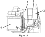
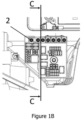
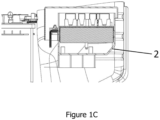
Figures 1A ,1B and1C are partial views of the engine compartment of a vehicle in which the hybrid power distribution central unit according to the present invention is arranged, respectively, in front, top and cross-sectional views; -
Figure 2 is a top elevational view of the hybrid power distribution central unit ofFigure 1 , with the cover removed in order to illustrate the modules layout; -
Figure 3 illustrates a schematic assembly sequence of the hybrid power distribution central unit; -
Figure 4 shows an exemplary catalog of functional and power supply modules designed to enable various application configurations; and -
Figure 5 shows an exploded perspective view of a power supply module. - According to the attached figures, with 1 there is generally indicated a hybrid power distribution central unit for vehicles according to the present invention. In particular, said hybrid power distribution
central unit 1 is defined by a housing (box) 2, provided with acover 3, which has inside it a plurality offunctional modules Figure 4 ), each having a particular and specific type. - More particularly, said housing (box) 2 has a specific shape and it is predesigned so as to be able to receive a certain amount of
modules - More particularly, said housing (box) 2 comprises a base 21 from which pairs of front and
rear walls 22 andside walls 23, respectively opposite each other, are designed. In the inner part of the front andrear walls 22 of the housing (box) there are further provided preferably L-cross section grooves 24. In addition, saidgrooves 24 are made in pairs, being the distance between eachgroove 24 of a pair of grooves is always constant and less than the width of any one of the functional modules 12-14. On the other hand, any one of the functional modules 12-14 also has respective L-shapedcross-sectional couplings 25, also in pairs, in order to allow the insertion of a pair ofcouplings 25 into a pair of housing (box 2)inner grooves 24. - As can be seen in
figure 2 , the HW technologyfunctional module 12 has a minimum width. In this case, saidmodule 12 has only a pair ofcouplings 25 which enter into the respectiveinternal grooves 24 of the housing (box) 2, thus occupying only one seat S3 of said housing (box) 2. ThePCB technology module 13 has a width which is twice the width of themodule 12 and thus has two pairs ofcouplings 25, which enter into two pairs ofgrooves 24, i.e., occupying the corresponding to two adjacent seats (for example S1 and S2) of the housing (box) 2. In the same sense, despite not being illustrated, a possible module having a width corresponding to three times the width of themodule 12 ofFigure 2 would have three pairs ofcouplings 25 and would thus occupy the space corresponding to three seats (for example, S1-3) of the housing (box) 2. - It should also be noted that in the modularization concept, regardless of the shape and / or dimensions of the housing (box) 2, the distance between the front and
rear walls 22 is constant and corresponds to the length of any one of the modules 12-14, while the distance between theside walls 23 varies according to the defined capacity of seats S1-n of the housing (box) 2. In addition, the coupling of any one of the functional modules 12-14 inside the housing (box) 2 ensures that the housing (box) 2 has an empty space between any one of the installed modules and the bottom of the housing (box) 2 itself. Such space is intended for the installation of respective connectors, for example, for the functional modules 12 (header), as well as for the installation of electric cables and wires that electrically connect each electrical element of the modules (fuse, actuator, relay, etc.) to the vehicle's electrical or electronic device (headlight, air conditioner, windshield wiper, etc.). In addition, the housing (box) 2 further hasapertures - Said
front wall 22 further has a lowered region (seeFigure 3 ) and is provided withfront couplings 26 in order to couple apower supply module 11 to saidwall 22. In particular, saidpower supply module 11 has an inverted L section shape, from which theequipotential pins 27 are projected (seeFigure 5 ), into which thecontacts 5 of the functional modules 12-14 are inserted, so as to supply electrical energy from the battery 4 (seefigure 1A ) to said functional modules. - As can be seen in
figure 5 , saidpower supply module 11 comprises a support structure 28 shaped so as to receive, by fitting, thepower supply busbar 29. On the sides of themodule 11 areprojections 31 which are intended to receive and couple the lower closing andbusbar 29 supportingcover 30. In addition, saidbusbar 29 is defined by ametal plate 32, on which are fixed, and preferably riveted, theelectrical contacts electrical contacts respective holes 35 able to couple themselves, by fitting and threading, to the electrical coupling pins 27 for thecontacts 5 of the functional modules 12-14. Obviously, as it is clear to any skilled person in the art, the number ofpins 5 and, therefore, the size of apower supply module 11 depends on the number of functional modules to be electrically fed, i.e. the size of housing (box) 2 and the amount of seats allotted in the housing (box) 2. - More particularly, on the body of the
metal plate 32,electrical contacts 34 as well aselectrical contacts 33, all them in the form of folded blades, are fixed by riveting but intermediated bypre-fuses 36. As a result, the functional modules 12-14 to be electrically fed by connection to one of saidelectrical contacts 33 are electrically protected by means of therespective pre-fuse 36. On the other hand, theelectrical contacts 34, which do not have the pre-fuses 36, can be reserved for power supply to any functional modules 12-14 which do not require this electrical protection, or may be used as extra electrical outputs or as an electric power supply for thebusbar 29 of thepower supply module 11. For example, anelectrical contact 33 may connect, by means of itsrespective pin 27, aHW 12 functional module in which only electrical fuses (connected to headlamps, flashlights, etc.) are arranged thus making the presence of a pre-fuse unnecessary. On the other hand, anelectrical contact 33, provided with a pre-fuse 36, may be intended for supplying power to afunctional module 14, of the PCB type, in which more sensitive electronic or electrical components, such as processors, sensors and the like are embedded. - With respect to said modules, examples of which are illustrated in
figure 4 , these can be functionally grouped, for example, in power supply modules (11A-C) and in the mentioned functional modules such as HW modules (12A-E), PCB modules (13A-D) and SL modules (14A-B). Each of these modules operates, from a functional point of view, in order to perform the functions related to each of its components, despite being the forms of assembly and connection specific and linked to the specific typology of the module in which these components are assembled. In addition, each of said modules, in particular, has a specific and predefined size. Thus, for example, in the illustrative modules shown infigure 4 , the overall dimension, in particular the width ofmodules HW 12E,PCB 13A or SL 14A, is twice the width ofmodules HW 12A, PCB 13D or SL 14B but is half the size of themodule 13C. Moreover, the PCB module 13D has similar size to saidHW modules modules - Such a feature is particularly interesting and important in the general concept of the present invention, since it allows modules of distinct types to be interchangeable with each other.
- A specific example of this concept is illustrated in
Figure 2 , wherein the housing (box) 2 has a first larger module installed, for example aPCB module HW module central unit 1 is installed, the aforementioned first module (PCB) could be replaced by a HW module, such as themodule 12E. - In order to guarantee the interchangeability of its components, regardless of the type of each one of these components, the housing (box) 2 further has an electrical power busbar, defined by one of the
power supply modules 11, in order to receive thecontacts 5 provided in each one of themodules battery 4 to any of the modules installed in the housing (box) 2, which increases said interchangeability of the modules 12-14 in each one of the defined seats S1-n. In order to do so, each one of the interchangeable modules must be designed so as to have therespective contact 5 in a predefined position. - Finally, said housing (box) 2 further has
apertures central unit 1. In particular, said openings may be formed in one of theside walls 23 of the housing (box) 2 (aperture 7) or may be apertures formed in thebase 21 of the housing (box) 2 (aperture 6). As a particularly interesting feature of the present invention, electrical wiring that electrically interconnects the hybrid power distributioncentral unit 1 to other vehicle's electric and electronic devices (lights, air conditioning, windshield wiper, sensors, etc.) does not require any kind of change, except the connection terminals of the various electrical wiring to the modules, which terminals must comply with the standardized connection form of the module type. -
Figure 3 is a schematic representation of the modules assembly inside the housing (box) 2 of the hybrid power distributioncentral unit 1. Thus, as soon as the functional needs of the hybrid power distribution central unit 1 (switching, current control, etc.) are defined, which are a function of the equipment and accessories installed in the vehicles, as a next step the more appropriate housing (box) 2 has to be choice / designed. It should be noted that, for a vehicle line, the functional needs for the most basic model and the most complete model must be taken into account. In other words, in order to determine the size and characteristics of the housing (box) 2, this should be made in function of all possible required combinations of modules / typology so as the hybrid power distributioncentral unit 1 to appropriately act in an appropriate way whatever is the specific vehicle in a possible vehicle line. - After these require features are defined, the housing (box) 2 is designed, the assembly of which initially comprises the installation of power supply to the modules, the HW modules connectors and the pre-fuse box. Thereafter, each of the functional modules assigned to a particular vehicle, on an assembly line, are sequentially coupled to the seats previously defined and connected. Finally, the
cover 3 and any further cover element are assembled, completing the hybrid power distributioncentral unit 1. - As can be observed, the modularization of the hybrid power distribution
central unit 1 shows itself in a highly positive way, since it allows being composed from individual modules, each one module being formed and defined by its own typology. As a result, each one of the functions of the hybrid power distributioncentral unit 1 can be performed through a respective module which is most appropriate in accordance with the particular characteristics thereof. In addition, and since the various modules are interchangeable in a previously defined seat or space, it is possible to adapt a particular housing (box) 2 in order to particularly use in a line of vehicles, whatever the control needs each vehicle has, depending on its accessories and embedded devices. - As a result, in addition to the time gained with the assembling of the hybrid power distribution
central unit 1, the solution described in the present invention still reveals substantial gains in the steps related to the design of the vehicle engine compartment and the electrical grid of a vehicle line. - Finally, due to its modularization, the said hybrid power distribution
central unit 1 can be configured through a previous catalog of components that, in a planned way, allows groupings of modules of different types and characteristics, making the solution, in addition of hybrid and modular, expandable and flexible. In addition, the hybrid power distribution central unit of the present invention is composed of functional modules that allow, as far as is required, the quantity of switching elements (Relays) and protection elements (Fuses) interconnected by cables or stamped metal busbars (Bus-Bars) that ensure the highest level of electrical protection and the least degree of the circuits complexity. As a result of these characteristics, it is possible, from a basic design of the hybrid power distribution central unit housing (box), to adapt its content and functionalities to several vehicle lines, even when such vehicles or vehicle lines are produced in different industrial plants and intended for different consumers and with particular regional requirements. From the design point of view, such a characteristic allows a great saving in terms of customization and regionalization of vehicle lines.
Claims (7)
- A hybrid power distribution central unit (1) for vehicles, characterized by a modular unit comprising, inside it, a plurality of seats S1-n of equivalent dimensions and capable of receiving at least one of a plurality of functional modules (12, 13, 14) of different types in respective one or more adjacent seats,wherein the hybrid power distribution central unit (1) comprises a housing box (2) defined by a base (21), side walls (23), front and rear walls (22) and cover (3), by defining internally a plurality of seats (S1-n) for coupling the functional modules (12, 13, 14),wherein each of the front and rear walls (22) of the housing box (2) has internally a pair of grooves (24) by seat (S1-n), and each pair of grooves (24) being able to receive a respective pair of couplings (25) of any one of the functional modules (12, 13, 14), andwherein the at least one of the plurality of functional modules (12, 13, 14) has a width equal to N times a width of the seat (S1-n) with n being an integer greater than or equal to 2, has N pairs of first couplings, and occupies N adjacent seats of the housing (2), andwherein on the outside of the front wall (22) of the housing box (2), directly below the lowered region of the housing box (2), there are provided second couplings (26) in order to couple a the power supply module (11),and wherein the power supply module (11) has inverted L-shape form, and the power supply module (11) comprises:- a busbar (29), in the form of a metal plate (32), on which the electrical contacts (33, 34) are fixed, said electrical contacts (33, 34) having respective holes (35) capable of coupling themselves, by fitting and thread coupling, to the pins (27) for the contacts (5) of the functional modules (12-14);- a support structure (28) that has a shape so as to receive the pins (27);- projections (31) of the structure (28) disposed on the sides of the power supply module (11) and intended to receive and couple a cover (30) supporting the busbar (29).
- A hybrid power distribution central unit, according to claim 1, wherein the power supply module (11) is intended to electrically feed all functional modules (12, 13, 14) coupled in respective seats (S1-n) of the housing (2).
- A hybrid power distribution central unit, according to claim 1 or 2, wherein said functional modules are HW (12), or PCB (13), or SL (14) type.
- A hybrid power distribution central unit, according to claims 1 or 2, wherein said functional modules HW (12), PCB (13) or SL (14) are selected in function of the controls and functionalities of the vehicle.
- A hybrid power distribution central unit, according to claim 1 or 2, wherein each groove (24) defines a longitudinal hollow opening and has a L-shaped cross-section, and each said first couplings (25) of the pair of grooves projects itself from the body of the respective functional module and having an L-shaped form.
- A hybrid power distribution central unit according to claim 5, wherein the electrical contacts (33) which interconnect the busbar (29) to the pins (27) comprise a pre-fuse (36).
- A vehicle comprising a hybrid power distribution central unit according to any one of claims from 1 to 6.
Applications Claiming Priority (3)
| Application Number | Priority Date | Filing Date | Title |
|---|---|---|---|
| BR102016017915A BR102016017915A2 (en) | 2016-08-02 | 2016-08-02 | hybrid vehicle power distribution center |
| BR102017016090-4A BR102017016090B1 (en) | 2017-07-27 | HYBRID ENERGY DISTRIBUTION PLANT FOR VEHICLES AND VEHICLES | |
| PCT/BR2017/050216 WO2018023185A1 (en) | 2016-08-02 | 2017-08-01 | Hybrid energy distribution plant for vehicles |
Publications (3)
| Publication Number | Publication Date |
|---|---|
| EP3496220A1 EP3496220A1 (en) | 2019-06-12 |
| EP3496220A4 EP3496220A4 (en) | 2020-04-01 |
| EP3496220B1 true EP3496220B1 (en) | 2023-04-26 |
Family
ID=61072434
Family Applications (1)
| Application Number | Title | Priority Date | Filing Date |
|---|---|---|---|
| EP17836115.0A Active EP3496220B1 (en) | 2016-08-02 | 2017-08-01 | Hybrid energy distribution plant for vehicles |
Country Status (6)
| Country | Link |
|---|---|
| US (1) | US10960834B2 (en) |
| EP (1) | EP3496220B1 (en) |
| CN (1) | CN109792139B (en) |
| CA (1) | CA3032742A1 (en) |
| MX (1) | MX393343B (en) |
| WO (1) | WO2018023185A1 (en) |
Families Citing this family (2)
| Publication number | Priority date | Publication date | Assignee | Title |
|---|---|---|---|---|
| CN112534539B (en) * | 2018-06-06 | 2024-08-13 | 力特保险丝公司 | Low Profile Integrated Fuse Modules |
| DE102022128805A1 (en) * | 2022-10-31 | 2024-05-02 | Audi Aktiengesellschaft | Connection device for electrically connecting a plurality of first electrical components to an energy storage device and connection arrangement |
Citations (1)
| Publication number | Priority date | Publication date | Assignee | Title |
|---|---|---|---|---|
| US20080200045A1 (en) * | 2007-02-15 | 2008-08-21 | Yazaki Corporation | Electric junction box |
Family Cites Families (21)
| Publication number | Priority date | Publication date | Assignee | Title |
|---|---|---|---|---|
| US4318156A (en) * | 1980-04-30 | 1982-03-02 | Gallagher Michael J | Portable distribution box |
| US4842534A (en) * | 1988-10-14 | 1989-06-27 | Interlock Corporation | Fuse/bus bar assembly |
| US5179503A (en) | 1991-04-19 | 1993-01-12 | United Technologies Automotive, Inc. | Modular automobile power distribution box |
| FR2690601B1 (en) * | 1992-04-22 | 2002-02-01 | Valeo Electronique | Service board for controlling and / or supplying electrical components to vehicles. |
| US5653607A (en) * | 1994-07-27 | 1997-08-05 | Sumitomo Wiring Systems, Ltd. | Electric connection casing |
| US5928004A (en) * | 1995-12-28 | 1999-07-27 | Sumitomo Wiring Systems, Ltd. | Electrical connection box for an automotive vehicle |
| EP1029743B1 (en) * | 1999-02-18 | 2009-04-22 | Continental Automotive GmbH | Vehicle modular electrical distribution centre |
| JP2001118487A (en) * | 1999-10-14 | 2001-04-27 | Sumitomo Wiring Syst Ltd | Electric connection box |
| DE60119610T2 (en) * | 2000-04-13 | 2007-04-26 | Sumitomo Wiring Systems, Ltd., Yokkaichi | Electrical connection housing |
| JP2003218554A (en) * | 2001-11-14 | 2003-07-31 | Yazaki Corp | Power distribution box and power device module |
| DE60226208T2 (en) * | 2002-02-14 | 2009-05-14 | Mta S.P.A., Codogno | Modular structure for holding fuses and modular fuse holders |
| US20070228826A1 (en) * | 2006-03-31 | 2007-10-04 | Jordan Patrick D | Modular, extensible electrical and communication systems, methods, and devices |
| JP5074744B2 (en) * | 2006-11-15 | 2012-11-14 | 矢崎総業株式会社 | Electrical junction box |
| EP1931003B1 (en) * | 2006-12-04 | 2009-05-27 | CRF Societa'Consortile per Azioni | Junction device for an electrical system, in particular for automobile applications |
| US7907423B2 (en) * | 2007-10-04 | 2011-03-15 | Tyco Electronics Brasil Ltda. | Modular power distribution assembly and method of making same |
| JP5625971B2 (en) * | 2011-02-08 | 2014-11-19 | 住友電装株式会社 | Internal circuit structure for electric junction box and electric junction box using the same |
| JP6441112B2 (en) * | 2014-04-21 | 2018-12-19 | 矢崎総業株式会社 | Electronic component unit and wire harness |
| JP6378939B2 (en) * | 2014-06-06 | 2018-08-22 | 矢崎総業株式会社 | Cassette type electrical junction box |
| JP6120822B2 (en) * | 2014-11-28 | 2017-04-26 | 矢崎総業株式会社 | Electrical junction box |
| CN104867796B (en) * | 2015-06-11 | 2016-11-16 | 安徽江淮汽车股份有限公司 | A kind of automobile fuse box |
| FR3040833B1 (en) * | 2015-09-04 | 2017-09-08 | Delphi France Sas | ELECTRICAL POWER DISTRIBUTION SYSTEM FOR VEHICLE |
-
2017
- 2017-08-01 WO PCT/BR2017/050216 patent/WO2018023185A1/en not_active Ceased
- 2017-08-01 US US16/321,678 patent/US10960834B2/en active Active
- 2017-08-01 CA CA3032742A patent/CA3032742A1/en active Pending
- 2017-08-01 MX MX2019001441A patent/MX393343B/en unknown
- 2017-08-01 CN CN201780060122.1A patent/CN109792139B/en active Active
- 2017-08-01 EP EP17836115.0A patent/EP3496220B1/en active Active
Patent Citations (1)
| Publication number | Priority date | Publication date | Assignee | Title |
|---|---|---|---|---|
| US20080200045A1 (en) * | 2007-02-15 | 2008-08-21 | Yazaki Corporation | Electric junction box |
Also Published As
| Publication number | Publication date |
|---|---|
| CN109792139B (en) | 2022-01-04 |
| EP3496220A4 (en) | 2020-04-01 |
| WO2018023185A1 (en) | 2018-02-08 |
| US10960834B2 (en) | 2021-03-30 |
| CN109792139A (en) | 2019-05-21 |
| MX393343B (en) | 2025-03-21 |
| US20200148138A1 (en) | 2020-05-14 |
| CA3032742A1 (en) | 2018-02-08 |
| EP3496220A1 (en) | 2019-06-12 |
| MX2019001441A (en) | 2019-09-27 |
Similar Documents
| Publication | Publication Date | Title |
|---|---|---|
| US8207454B2 (en) | Electrical junction box | |
| CN101312287B (en) | electrical connection box | |
| EP0701924B1 (en) | Electrical connection box | |
| CN101577405B (en) | Electric junction box | |
| US8471670B2 (en) | Fusible link unit | |
| CN102403683B (en) | Connector cover and junction box unit provided with same | |
| US9397485B2 (en) | Electrical distribution center | |
| JP2009189193A (en) | Electrical junction box | |
| CN101815635B (en) | Modular power distribution assembly and method of making same | |
| WO2009032019A1 (en) | Modular power distribution center | |
| EP3496220B1 (en) | Hybrid energy distribution plant for vehicles | |
| JP2014193073A (en) | Electric connection box | |
| US20060258186A1 (en) | Electric distribution box | |
| CN110962770A (en) | Automobile electrical box and method for preventing wire harness from falling off | |
| JP5605637B2 (en) | Electrical component control system | |
| US5735713A (en) | Electrical junction box | |
| JP2022108154A (en) | In-vehicle device | |
| BR102017016090B1 (en) | HYBRID ENERGY DISTRIBUTION PLANT FOR VEHICLES AND VEHICLES | |
| KR100609449B1 (en) | Junction box | |
| JP2007043827A (en) | Device arrangement structure and fuse circuit body used in device arrangement structure | |
| JP7655799B2 (en) | Power Distribution Block | |
| JPH09215154A (en) | Electrical junction box | |
| US20160285244A1 (en) | Electronic component unit and electric connection box | |
| JP2022101133A (en) | Electric connection box | |
| JP4394042B2 (en) | Electrical junction box |
Legal Events
| Date | Code | Title | Description |
|---|---|---|---|
| STAA | Information on the status of an ep patent application or granted ep patent |
Free format text: STATUS: THE INTERNATIONAL PUBLICATION HAS BEEN MADE |
|
| PUAI | Public reference made under article 153(3) epc to a published international application that has entered the european phase |
Free format text: ORIGINAL CODE: 0009012 |
|
| STAA | Information on the status of an ep patent application or granted ep patent |
Free format text: STATUS: REQUEST FOR EXAMINATION WAS MADE |
|
| 17P | Request for examination filed |
Effective date: 20190301 |
|
| AK | Designated contracting states |
Kind code of ref document: A1 Designated state(s): AL AT BE BG CH CY CZ DE DK EE ES FI FR GB GR HR HU IE IS IT LI LT LU LV MC MK MT NL NO PL PT RO RS SE SI SK SM TR |
|
| AX | Request for extension of the european patent |
Extension state: BA ME |
|
| DAV | Request for validation of the european patent (deleted) | ||
| DAX | Request for extension of the european patent (deleted) | ||
| A4 | Supplementary search report drawn up and despatched |
Effective date: 20200304 |
|
| RIC1 | Information provided on ipc code assigned before grant |
Ipc: B60R 16/023 20060101ALI20200227BHEP Ipc: H01H 85/20 20060101ALI20200227BHEP Ipc: B60R 16/02 20060101ALI20200227BHEP Ipc: H02G 3/08 20060101AFI20200227BHEP |
|
| STAA | Information on the status of an ep patent application or granted ep patent |
Free format text: STATUS: EXAMINATION IS IN PROGRESS |
|
| 17Q | First examination report despatched |
Effective date: 20220318 |
|
| GRAP | Despatch of communication of intention to grant a patent |
Free format text: ORIGINAL CODE: EPIDOSNIGR1 |
|
| STAA | Information on the status of an ep patent application or granted ep patent |
Free format text: STATUS: GRANT OF PATENT IS INTENDED |
|
| INTG | Intention to grant announced |
Effective date: 20221111 |
|
| GRAS | Grant fee paid |
Free format text: ORIGINAL CODE: EPIDOSNIGR3 |
|
| GRAA | (expected) grant |
Free format text: ORIGINAL CODE: 0009210 |
|
| STAA | Information on the status of an ep patent application or granted ep patent |
Free format text: STATUS: THE PATENT HAS BEEN GRANTED |
|
| AK | Designated contracting states |
Kind code of ref document: B1 Designated state(s): AL AT BE BG CH CY CZ DE DK EE ES FI FR GB GR HR HU IE IS IT LI LT LU LV MC MK MT NL NO PL PT RO RS SE SI SK SM TR |
|
| REG | Reference to a national code |
Ref country code: GB Ref legal event code: FG4D |
|
| REG | Reference to a national code |
Ref country code: CH Ref legal event code: EP |
|
| REG | Reference to a national code |
Ref country code: DE Ref legal event code: R096 Ref document number: 602017068140 Country of ref document: DE |
|
| REG | Reference to a national code |
Ref country code: AT Ref legal event code: REF Ref document number: 1563527 Country of ref document: AT Kind code of ref document: T Effective date: 20230515 |
|
| REG | Reference to a national code |
Ref country code: IE Ref legal event code: FG4D |
|
| REG | Reference to a national code |
Ref country code: LT Ref legal event code: MG9D |
|
| REG | Reference to a national code |
Ref country code: NL Ref legal event code: MP Effective date: 20230426 |
|
| REG | Reference to a national code |
Ref country code: AT Ref legal event code: MK05 Ref document number: 1563527 Country of ref document: AT Kind code of ref document: T Effective date: 20230426 |
|
| PG25 | Lapsed in a contracting state [announced via postgrant information from national office to epo] |
Ref country code: NL Free format text: LAPSE BECAUSE OF FAILURE TO SUBMIT A TRANSLATION OF THE DESCRIPTION OR TO PAY THE FEE WITHIN THE PRESCRIBED TIME-LIMIT Effective date: 20230426 |
|
| PG25 | Lapsed in a contracting state [announced via postgrant information from national office to epo] |
Ref country code: SE Free format text: LAPSE BECAUSE OF FAILURE TO SUBMIT A TRANSLATION OF THE DESCRIPTION OR TO PAY THE FEE WITHIN THE PRESCRIBED TIME-LIMIT Effective date: 20230426 Ref country code: PT Free format text: LAPSE BECAUSE OF FAILURE TO SUBMIT A TRANSLATION OF THE DESCRIPTION OR TO PAY THE FEE WITHIN THE PRESCRIBED TIME-LIMIT Effective date: 20230828 Ref country code: NO Free format text: LAPSE BECAUSE OF FAILURE TO SUBMIT A TRANSLATION OF THE DESCRIPTION OR TO PAY THE FEE WITHIN THE PRESCRIBED TIME-LIMIT Effective date: 20230726 Ref country code: ES Free format text: LAPSE BECAUSE OF FAILURE TO SUBMIT A TRANSLATION OF THE DESCRIPTION OR TO PAY THE FEE WITHIN THE PRESCRIBED TIME-LIMIT Effective date: 20230426 Ref country code: AT Free format text: LAPSE BECAUSE OF FAILURE TO SUBMIT A TRANSLATION OF THE DESCRIPTION OR TO PAY THE FEE WITHIN THE PRESCRIBED TIME-LIMIT Effective date: 20230426 |
|
| PG25 | Lapsed in a contracting state [announced via postgrant information from national office to epo] |
Ref country code: RS Free format text: LAPSE BECAUSE OF FAILURE TO SUBMIT A TRANSLATION OF THE DESCRIPTION OR TO PAY THE FEE WITHIN THE PRESCRIBED TIME-LIMIT Effective date: 20230426 Ref country code: PL Free format text: LAPSE BECAUSE OF FAILURE TO SUBMIT A TRANSLATION OF THE DESCRIPTION OR TO PAY THE FEE WITHIN THE PRESCRIBED TIME-LIMIT Effective date: 20230426 Ref country code: LV Free format text: LAPSE BECAUSE OF FAILURE TO SUBMIT A TRANSLATION OF THE DESCRIPTION OR TO PAY THE FEE WITHIN THE PRESCRIBED TIME-LIMIT Effective date: 20230426 Ref country code: LT Free format text: LAPSE BECAUSE OF FAILURE TO SUBMIT A TRANSLATION OF THE DESCRIPTION OR TO PAY THE FEE WITHIN THE PRESCRIBED TIME-LIMIT Effective date: 20230426 Ref country code: IS Free format text: LAPSE BECAUSE OF FAILURE TO SUBMIT A TRANSLATION OF THE DESCRIPTION OR TO PAY THE FEE WITHIN THE PRESCRIBED TIME-LIMIT Effective date: 20230826 Ref country code: HR Free format text: LAPSE BECAUSE OF FAILURE TO SUBMIT A TRANSLATION OF THE DESCRIPTION OR TO PAY THE FEE WITHIN THE PRESCRIBED TIME-LIMIT Effective date: 20230426 Ref country code: GR Free format text: LAPSE BECAUSE OF FAILURE TO SUBMIT A TRANSLATION OF THE DESCRIPTION OR TO PAY THE FEE WITHIN THE PRESCRIBED TIME-LIMIT Effective date: 20230727 |
|
| PG25 | Lapsed in a contracting state [announced via postgrant information from national office to epo] |
Ref country code: FI Free format text: LAPSE BECAUSE OF FAILURE TO SUBMIT A TRANSLATION OF THE DESCRIPTION OR TO PAY THE FEE WITHIN THE PRESCRIBED TIME-LIMIT Effective date: 20230426 |
|
| PG25 | Lapsed in a contracting state [announced via postgrant information from national office to epo] |
Ref country code: SK Free format text: LAPSE BECAUSE OF FAILURE TO SUBMIT A TRANSLATION OF THE DESCRIPTION OR TO PAY THE FEE WITHIN THE PRESCRIBED TIME-LIMIT Effective date: 20230426 |
|
| REG | Reference to a national code |
Ref country code: DE Ref legal event code: R097 Ref document number: 602017068140 Country of ref document: DE |
|
| PG25 | Lapsed in a contracting state [announced via postgrant information from national office to epo] |
Ref country code: SM Free format text: LAPSE BECAUSE OF FAILURE TO SUBMIT A TRANSLATION OF THE DESCRIPTION OR TO PAY THE FEE WITHIN THE PRESCRIBED TIME-LIMIT Effective date: 20230426 Ref country code: SK Free format text: LAPSE BECAUSE OF FAILURE TO SUBMIT A TRANSLATION OF THE DESCRIPTION OR TO PAY THE FEE WITHIN THE PRESCRIBED TIME-LIMIT Effective date: 20230426 Ref country code: RO Free format text: LAPSE BECAUSE OF FAILURE TO SUBMIT A TRANSLATION OF THE DESCRIPTION OR TO PAY THE FEE WITHIN THE PRESCRIBED TIME-LIMIT Effective date: 20230426 Ref country code: EE Free format text: LAPSE BECAUSE OF FAILURE TO SUBMIT A TRANSLATION OF THE DESCRIPTION OR TO PAY THE FEE WITHIN THE PRESCRIBED TIME-LIMIT Effective date: 20230426 Ref country code: DK Free format text: LAPSE BECAUSE OF FAILURE TO SUBMIT A TRANSLATION OF THE DESCRIPTION OR TO PAY THE FEE WITHIN THE PRESCRIBED TIME-LIMIT Effective date: 20230426 Ref country code: CZ Free format text: LAPSE BECAUSE OF FAILURE TO SUBMIT A TRANSLATION OF THE DESCRIPTION OR TO PAY THE FEE WITHIN THE PRESCRIBED TIME-LIMIT Effective date: 20230426 |
|
| PLBE | No opposition filed within time limit |
Free format text: ORIGINAL CODE: 0009261 |
|
| STAA | Information on the status of an ep patent application or granted ep patent |
Free format text: STATUS: NO OPPOSITION FILED WITHIN TIME LIMIT |
|
| PG25 | Lapsed in a contracting state [announced via postgrant information from national office to epo] |
Ref country code: MC Free format text: LAPSE BECAUSE OF FAILURE TO SUBMIT A TRANSLATION OF THE DESCRIPTION OR TO PAY THE FEE WITHIN THE PRESCRIBED TIME-LIMIT Effective date: 20230426 |
|
| REG | Reference to a national code |
Ref country code: CH Ref legal event code: PL |
|
| PG25 | Lapsed in a contracting state [announced via postgrant information from national office to epo] |
Ref country code: MC Free format text: LAPSE BECAUSE OF FAILURE TO SUBMIT A TRANSLATION OF THE DESCRIPTION OR TO PAY THE FEE WITHIN THE PRESCRIBED TIME-LIMIT Effective date: 20230426 |
|
| 26N | No opposition filed |
Effective date: 20240129 |
|
| PG25 | Lapsed in a contracting state [announced via postgrant information from national office to epo] |
Ref country code: LU Free format text: LAPSE BECAUSE OF NON-PAYMENT OF DUE FEES Effective date: 20230801 |
|
| PG25 | Lapsed in a contracting state [announced via postgrant information from national office to epo] |
Ref country code: LU Free format text: LAPSE BECAUSE OF NON-PAYMENT OF DUE FEES Effective date: 20230801 Ref country code: CH Free format text: LAPSE BECAUSE OF NON-PAYMENT OF DUE FEES Effective date: 20230831 |
|
| PG25 | Lapsed in a contracting state [announced via postgrant information from national office to epo] |
Ref country code: SI Free format text: LAPSE BECAUSE OF FAILURE TO SUBMIT A TRANSLATION OF THE DESCRIPTION OR TO PAY THE FEE WITHIN THE PRESCRIBED TIME-LIMIT Effective date: 20230426 |
|
| REG | Reference to a national code |
Ref country code: BE Ref legal event code: MM Effective date: 20230831 |
|
| REG | Reference to a national code |
Ref country code: IE Ref legal event code: MM4A |
|
| PG25 | Lapsed in a contracting state [announced via postgrant information from national office to epo] |
Ref country code: SI Free format text: LAPSE BECAUSE OF FAILURE TO SUBMIT A TRANSLATION OF THE DESCRIPTION OR TO PAY THE FEE WITHIN THE PRESCRIBED TIME-LIMIT Effective date: 20230426 |
|
| PG25 | Lapsed in a contracting state [announced via postgrant information from national office to epo] |
Ref country code: IE Free format text: LAPSE BECAUSE OF NON-PAYMENT OF DUE FEES Effective date: 20230801 |
|
| PG25 | Lapsed in a contracting state [announced via postgrant information from national office to epo] |
Ref country code: IE Free format text: LAPSE BECAUSE OF NON-PAYMENT OF DUE FEES Effective date: 20230801 |
|
| PG25 | Lapsed in a contracting state [announced via postgrant information from national office to epo] |
Ref country code: BE Free format text: LAPSE BECAUSE OF NON-PAYMENT OF DUE FEES Effective date: 20230831 |
|
| PG25 | Lapsed in a contracting state [announced via postgrant information from national office to epo] |
Ref country code: BG Free format text: LAPSE BECAUSE OF FAILURE TO SUBMIT A TRANSLATION OF THE DESCRIPTION OR TO PAY THE FEE WITHIN THE PRESCRIBED TIME-LIMIT Effective date: 20230426 |
|
| PG25 | Lapsed in a contracting state [announced via postgrant information from national office to epo] |
Ref country code: BG Free format text: LAPSE BECAUSE OF FAILURE TO SUBMIT A TRANSLATION OF THE DESCRIPTION OR TO PAY THE FEE WITHIN THE PRESCRIBED TIME-LIMIT Effective date: 20230426 |
|
| PG25 | Lapsed in a contracting state [announced via postgrant information from national office to epo] |
Ref country code: CY Free format text: LAPSE BECAUSE OF FAILURE TO SUBMIT A TRANSLATION OF THE DESCRIPTION OR TO PAY THE FEE WITHIN THE PRESCRIBED TIME-LIMIT; INVALID AB INITIO Effective date: 20170801 |
|
| PG25 | Lapsed in a contracting state [announced via postgrant information from national office to epo] |
Ref country code: HU Free format text: LAPSE BECAUSE OF FAILURE TO SUBMIT A TRANSLATION OF THE DESCRIPTION OR TO PAY THE FEE WITHIN THE PRESCRIBED TIME-LIMIT; INVALID AB INITIO Effective date: 20170801 |
|
| PGFP | Annual fee paid to national office [announced via postgrant information from national office to epo] |
Ref country code: DE Payment date: 20250724 Year of fee payment: 9 |
|
| PGFP | Annual fee paid to national office [announced via postgrant information from national office to epo] |
Ref country code: IT Payment date: 20250723 Year of fee payment: 9 |
|
| PGFP | Annual fee paid to national office [announced via postgrant information from national office to epo] |
Ref country code: GB Payment date: 20250725 Year of fee payment: 9 |
|
| PGFP | Annual fee paid to national office [announced via postgrant information from national office to epo] |
Ref country code: FR Payment date: 20250725 Year of fee payment: 9 |
|
| PG25 | Lapsed in a contracting state [announced via postgrant information from national office to epo] |
Ref country code: TR Free format text: LAPSE BECAUSE OF FAILURE TO SUBMIT A TRANSLATION OF THE DESCRIPTION OR TO PAY THE FEE WITHIN THE PRESCRIBED TIME-LIMIT Effective date: 20230426 |