EP3496088A1 - Additively manufactured septa for acoustic panels - Google Patents
Additively manufactured septa for acoustic panels Download PDFInfo
- Publication number
- EP3496088A1 EP3496088A1 EP18194173.3A EP18194173A EP3496088A1 EP 3496088 A1 EP3496088 A1 EP 3496088A1 EP 18194173 A EP18194173 A EP 18194173A EP 3496088 A1 EP3496088 A1 EP 3496088A1
- Authority
- EP
- European Patent Office
- Prior art keywords
- layers
- acoustic
- layer
- septum
- stack
- Prior art date
- Legal status (The legal status is an assumption and is not a legal conclusion. Google has not performed a legal analysis and makes no representation as to the accuracy of the status listed.)
- Granted
Links
Images


Classifications
-
- G—PHYSICS
- G10—MUSICAL INSTRUMENTS; ACOUSTICS
- G10K—SOUND-PRODUCING DEVICES; METHODS OR DEVICES FOR PROTECTING AGAINST, OR FOR DAMPING, NOISE OR OTHER ACOUSTIC WAVES IN GENERAL; ACOUSTICS NOT OTHERWISE PROVIDED FOR
- G10K11/00—Methods or devices for transmitting, conducting or directing sound in general; Methods or devices for protecting against, or for damping, noise or other acoustic waves in general
- G10K11/16—Methods or devices for protecting against, or for damping, noise or other acoustic waves in general
-
- B—PERFORMING OPERATIONS; TRANSPORTING
- B29—WORKING OF PLASTICS; WORKING OF SUBSTANCES IN A PLASTIC STATE IN GENERAL
- B29C—SHAPING OR JOINING OF PLASTICS; SHAPING OF MATERIAL IN A PLASTIC STATE, NOT OTHERWISE PROVIDED FOR; AFTER-TREATMENT OF THE SHAPED PRODUCTS, e.g. REPAIRING
- B29C64/00—Additive manufacturing, i.e. manufacturing of three-dimensional [3D] objects by additive deposition, additive agglomeration or additive layering, e.g. by 3D printing, stereolithography or selective laser sintering
- B29C64/10—Processes of additive manufacturing
- B29C64/106—Processes of additive manufacturing using only liquids or viscous materials, e.g. depositing a continuous bead of viscous material
-
- B—PERFORMING OPERATIONS; TRANSPORTING
- B29—WORKING OF PLASTICS; WORKING OF SUBSTANCES IN A PLASTIC STATE IN GENERAL
- B29D—PRODUCING PARTICULAR ARTICLES FROM PLASTICS OR FROM SUBSTANCES IN A PLASTIC STATE
- B29D99/00—Subject matter not provided for in other groups of this subclass
- B29D99/0089—Producing honeycomb structures
-
- B—PERFORMING OPERATIONS; TRANSPORTING
- B33—ADDITIVE MANUFACTURING TECHNOLOGY
- B33Y—ADDITIVE MANUFACTURING, i.e. MANUFACTURING OF THREE-DIMENSIONAL [3D] OBJECTS BY ADDITIVE DEPOSITION, ADDITIVE AGGLOMERATION OR ADDITIVE LAYERING, e.g. BY 3D PRINTING, STEREOLITHOGRAPHY OR SELECTIVE LASER SINTERING
- B33Y10/00—Processes of additive manufacturing
-
- B—PERFORMING OPERATIONS; TRANSPORTING
- B33—ADDITIVE MANUFACTURING TECHNOLOGY
- B33Y—ADDITIVE MANUFACTURING, i.e. MANUFACTURING OF THREE-DIMENSIONAL [3D] OBJECTS BY ADDITIVE DEPOSITION, ADDITIVE AGGLOMERATION OR ADDITIVE LAYERING, e.g. BY 3D PRINTING, STEREOLITHOGRAPHY OR SELECTIVE LASER SINTERING
- B33Y30/00—Apparatus for additive manufacturing; Details thereof or accessories therefor
-
- B—PERFORMING OPERATIONS; TRANSPORTING
- B33—ADDITIVE MANUFACTURING TECHNOLOGY
- B33Y—ADDITIVE MANUFACTURING, i.e. MANUFACTURING OF THREE-DIMENSIONAL [3D] OBJECTS BY ADDITIVE DEPOSITION, ADDITIVE AGGLOMERATION OR ADDITIVE LAYERING, e.g. BY 3D PRINTING, STEREOLITHOGRAPHY OR SELECTIVE LASER SINTERING
- B33Y80/00—Products made by additive manufacturing
-
- B—PERFORMING OPERATIONS; TRANSPORTING
- B64—AIRCRAFT; AVIATION; COSMONAUTICS
- B64C—AEROPLANES; HELICOPTERS
- B64C1/00—Fuselages; Constructional features common to fuselages, wings, stabilising surfaces or the like
- B64C1/40—Sound or heat insulation, e.g. using insulation blankets
-
- G—PHYSICS
- G10—MUSICAL INSTRUMENTS; ACOUSTICS
- G10K—SOUND-PRODUCING DEVICES; METHODS OR DEVICES FOR PROTECTING AGAINST, OR FOR DAMPING, NOISE OR OTHER ACOUSTIC WAVES IN GENERAL; ACOUSTICS NOT OTHERWISE PROVIDED FOR
- G10K11/00—Methods or devices for transmitting, conducting or directing sound in general; Methods or devices for protecting against, or for damping, noise or other acoustic waves in general
- G10K11/16—Methods or devices for protecting against, or for damping, noise or other acoustic waves in general
- G10K11/172—Methods or devices for protecting against, or for damping, noise or other acoustic waves in general using resonance effects
-
- B—PERFORMING OPERATIONS; TRANSPORTING
- B29—WORKING OF PLASTICS; WORKING OF SUBSTANCES IN A PLASTIC STATE IN GENERAL
- B29K—INDEXING SCHEME ASSOCIATED WITH SUBCLASSES B29B, B29C OR B29D, RELATING TO MOULDING MATERIALS OR TO MATERIALS FOR MOULDS, REINFORCEMENTS, FILLERS OR PREFORMED PARTS, e.g. INSERTS
- B29K2701/00—Use of unspecified macromolecular compounds for preformed parts, e.g. for inserts
- B29K2701/12—Thermoplastic materials
-
- B—PERFORMING OPERATIONS; TRANSPORTING
- B29—WORKING OF PLASTICS; WORKING OF SUBSTANCES IN A PLASTIC STATE IN GENERAL
- B29L—INDEXING SCHEME ASSOCIATED WITH SUBCLASS B29C, RELATING TO PARTICULAR ARTICLES
- B29L2007/00—Flat articles, e.g. films or sheets
- B29L2007/002—Panels; Plates; Sheets
-
- B—PERFORMING OPERATIONS; TRANSPORTING
- B32—LAYERED PRODUCTS
- B32B—LAYERED PRODUCTS, i.e. PRODUCTS BUILT-UP OF STRATA OF FLAT OR NON-FLAT, e.g. CELLULAR OR HONEYCOMB, FORM
- B32B2260/00—Layered product comprising an impregnated, embedded, or bonded layer wherein the layer comprises an impregnation, embedding, or binder material
- B32B2260/02—Composition of the impregnated, bonded or embedded layer
- B32B2260/021—Fibrous or filamentary layer
- B32B2260/023—Two or more layers
-
- B—PERFORMING OPERATIONS; TRANSPORTING
- B32—LAYERED PRODUCTS
- B32B—LAYERED PRODUCTS, i.e. PRODUCTS BUILT-UP OF STRATA OF FLAT OR NON-FLAT, e.g. CELLULAR OR HONEYCOMB, FORM
- B32B2307/00—Properties of the layers or laminate
- B32B2307/10—Properties of the layers or laminate having particular acoustical properties
-
- B—PERFORMING OPERATIONS; TRANSPORTING
- B32—LAYERED PRODUCTS
- B32B—LAYERED PRODUCTS, i.e. PRODUCTS BUILT-UP OF STRATA OF FLAT OR NON-FLAT, e.g. CELLULAR OR HONEYCOMB, FORM
- B32B2605/00—Vehicles
- B32B2605/18—Aircraft
-
- B—PERFORMING OPERATIONS; TRANSPORTING
- B64—AIRCRAFT; AVIATION; COSMONAUTICS
- B64D—EQUIPMENT FOR FITTING IN OR TO AIRCRAFT; FLIGHT SUITS; PARACHUTES; ARRANGEMENT OR MOUNTING OF POWER PLANTS OR PROPULSION TRANSMISSIONS IN AIRCRAFT
- B64D33/00—Arrangement in aircraft of power plant parts or auxiliaries not otherwise provided for
- B64D33/02—Arrangement in aircraft of power plant parts or auxiliaries not otherwise provided for of combustion air intakes
- B64D2033/0206—Arrangement in aircraft of power plant parts or auxiliaries not otherwise provided for of combustion air intakes comprising noise reduction means, e.g. acoustic liners
-
- G—PHYSICS
- G10—MUSICAL INSTRUMENTS; ACOUSTICS
- G10K—SOUND-PRODUCING DEVICES; METHODS OR DEVICES FOR PROTECTING AGAINST, OR FOR DAMPING, NOISE OR OTHER ACOUSTIC WAVES IN GENERAL; ACOUSTICS NOT OTHERWISE PROVIDED FOR
- G10K2210/00—Details of active noise control [ANC] covered by G10K11/178 but not provided for in any of its subgroups
- G10K2210/10—Applications
- G10K2210/121—Rotating machines, e.g. engines, turbines, motors; Periodic or quasi-periodic signals in general
-
- G—PHYSICS
- G10—MUSICAL INSTRUMENTS; ACOUSTICS
- G10K—SOUND-PRODUCING DEVICES; METHODS OR DEVICES FOR PROTECTING AGAINST, OR FOR DAMPING, NOISE OR OTHER ACOUSTIC WAVES IN GENERAL; ACOUSTICS NOT OTHERWISE PROVIDED FOR
- G10K2210/00—Details of active noise control [ANC] covered by G10K11/178 but not provided for in any of its subgroups
- G10K2210/10—Applications
- G10K2210/128—Vehicles
- G10K2210/1281—Aircraft, e.g. spacecraft, airplane or helicopter
-
- G—PHYSICS
- G10—MUSICAL INSTRUMENTS; ACOUSTICS
- G10K—SOUND-PRODUCING DEVICES; METHODS OR DEVICES FOR PROTECTING AGAINST, OR FOR DAMPING, NOISE OR OTHER ACOUSTIC WAVES IN GENERAL; ACOUSTICS NOT OTHERWISE PROVIDED FOR
- G10K2210/00—Details of active noise control [ANC] covered by G10K11/178 but not provided for in any of its subgroups
- G10K2210/30—Means
- G10K2210/321—Physical
- G10K2210/3223—Materials, e.g. special compositions or gases
-
- Y—GENERAL TAGGING OF NEW TECHNOLOGICAL DEVELOPMENTS; GENERAL TAGGING OF CROSS-SECTIONAL TECHNOLOGIES SPANNING OVER SEVERAL SECTIONS OF THE IPC; TECHNICAL SUBJECTS COVERED BY FORMER USPC CROSS-REFERENCE ART COLLECTIONS [XRACs] AND DIGESTS
- Y02—TECHNOLOGIES OR APPLICATIONS FOR MITIGATION OR ADAPTATION AGAINST CLIMATE CHANGE
- Y02T—CLIMATE CHANGE MITIGATION TECHNOLOGIES RELATED TO TRANSPORTATION
- Y02T50/00—Aeronautics or air transport
- Y02T50/60—Efficient propulsion technologies, e.g. for aircraft
Definitions
- the disclosure relates to the field of acoustic panels, and in particular, to septa for acoustic panels.
- Acoustic panels include structures that are specifically designed to absorb, control and/or reflect sound. For example, acoustic panels may be utilized to reduce the noise impact of aircraft engines during takeoff, flight, and landing. Acoustic panels within an aircraft may further be utilized to reduce and/or redirect aircraft noise away from bystanders that may be proximate to an aircraft during takeoff and landing.
- acoustic panels are painstakingly assembled cell by cell in order to conform each panel to the complex geometries of an aircraft.
- a septum is inserted into each of these cells to facilitate acoustic control, and there may be tens of thousands of septa within the acoustic panels for an aircraft.
- Such intensive processes for inserting septa into acoustic panels increase the expense of manufacturing an aircraft, and are therefore undesirable.
- designers of aircraft carefully balance concerns of comfort and cost when adding acoustic panels to an aircraft.
- Embodiments described herein provide septa that are fabricated via additive manufacturing processes. These septa may therefore be fabricated as integral components of acoustic cells and/or panels.
- the septa described herein utilize a unique multi-layer geometry that provides a desired size and number of flow pathways into a corresponding inner chamber of an acoustic cell. This eliminates the need for septa that are made from different materials than their corresponding acoustic cells. Further, this eliminates the need for separate processes of insertion and bonding of septa into their acoustic cells. Still further, because the size and number of flow pathways can be precisely controlled at the design stage, the septa described herein enable precisely calibrated acoustic control.
- One embodiment is a method that includes fabricating a septum of a cell of an acoustic panel, by heating a material into a molten material, depositing the molten material to form a lower chamber of the septum that extends vertically upwards and includes an entry, iteratively depositing layers of the molten material, each layer comprising a filament at the entry that includes overhangs with respect to vertically adjacent layers, and forming openings at locations of the overhangs.
- a further embodiment is a non-transitory computer readable medium embodying programmed instructions which, when executed by a processor, are operable for performing a method.
- the method includes fabricating a septum of a cell of an acoustic panel, by heating a material into a molten material, depositing the molten material to form a lower chamber of the septum that extends vertically upwards and includes an entry, iteratively depositing layers of the molten material, each layer comprising a filament at the entry that includes overhangs with respect to vertically adjacent layers, and forming openings at locations of the overhangs.
- a further embodiment is an apparatus that includes a septum of an acoustic cell.
- the septum includes a lower chamber that extends vertically upwards and includes an entry, and a stack comprising layers of material disposed atop the entry of the lower chamber.
- Each layer of the stack comprises a filament at the entry and includes overhangs with respect to vertically adjacent layers, and openings that are disposed between the layers at locations of the overhangs and that result from the overhangs extending beyond adjacent layers.
- FIG. 1 is a side view of a septum 100 for an acoustic cell in an illustrative embodiment.
- Septum 100 comprises an integral material (e.g., a thermoplastic part) that provides small flow pathways (e.g., having diameters between one ten thousandth of an inch and one thousandth of an inch) into a lower chamber 150 that extends vertically upwards and includes an entry 132. This facilitates control of acoustic energy when septum 100 is placed within an acoustic cell.
- an integral material e.g., a thermoplastic part
- small flow pathways e.g., having diameters between one ten thousandth of an inch and one thousandth of an inch
- septum 100 comprises three regions, each of which may be made from a thermoplastic such as Poly Aryl Ether Ketone (PAEK), a polycarbonate (PC) polyetherimide (PEI) blend, etc.
- a thermoplastic such as Poly Aryl Ether Ketone (PAEK), a polycarbonate (PC) polyetherimide (PEI) blend, etc.
- PEEK Poly Aryl Ether Ketone
- PC polycarbonate
- PEI polyetherimide
- Region 142 includes wall 144 (e.g., a solid wall of thermoplastic), which surrounds and defines lower chamber 150.
- Ramp 130 is a portion of wall 144 that decreases a diameter (D) of lower chamber 150 until reaching the entry 132.
- An angle at which ramp 130 proceeds may depend upon a maximum ramp angle allowed by the additive manufacturing process.
- a maximum ramp angle for a fused filament fabrication system is forty five degrees
- the angle ( ⁇ ) of ramp 130 may be limited to forty five degrees.
- Perimeter 140 surrounds the entry 132.
- Lower chamber 150 may be fabricated via fused filament fabrication, or any other suitable process.
- Region 122 includes stack 120, which includes multiple layers 124 of material.
- the geometry of layers 124 creates small openings/flow pathways between layers 124, which facilitates control of acoustic energy within an acoustic cell.
- Region 112 defines a cap 110, such as a solid cap for septum 100. While a cap 110 that is solid is illustrated in FIG. 1 , in further embodiments, cap 110 may comprise an additional amount of the layers 124. These additional layers may decrease in diameter as they are additively manufactured and stacked on top of each other to form a cone-like structure. Such an embodiment enables the placement of flow pathways within cap 110.
- cap 110 may be fabricated completely flat, so long as cap 110 is fabricated such that it forms a base layer of septum 100 (e.g., so long as septum 100 is fabricated upside-down, from the top downwards). Regardless of the type of cap 110 utilized by septum 100, septum 100 does not include any flow pathways larger than those defined by the gaps between layers 124 (e.g., no flow pathways have a diameter larger than ten thousandths of an inch).
- FIG. 2 is a section cut of multiple layers of septum 100 of FIG. 1 in an illustrative embodiment, and corresponds with view arrows 2 of FIG. 1 .
- first layer 210 and additional layer 220 are illustrated.
- Each layer comprises a single pathway of deposited material that follows perimeter 140 of FIG. 1 , such as thermoplastic deposited by a single nozzle of a fused filament fabrication system.
- each layer forms a shape that is hollow and bounded, such as a filament 216 defining a multi-pointed star shape formed from vertices 260 comprising N protrusions 214 and recesses 212.
- the shape of additional layer 220 is rotated with respect to first layer 210. This causes vertices 260 in additional layer 220 to be offset from vertices 260 in first layer 210. The offset may result from a translation or a rotation of vertices 260 that are in different layers.
- protrusions 224 at additional layer 220 may partially cover recesses 212 of first layer 210, resulting in overhangs 290 wherein a portion of one layer extends laterally beyond a portion/border/boundary of a vertically adjacent layer. Recesses in each layer therefore align with protrusions of adjacent layers. In this manner, the hollow portion 250 of each layer (positioned over entry 132) extends beyond adjacent layers. Phrased differently, a hollow portion 250 of additional layer 220 extends beyond filament 216 of an adjacent layer (e.g., first layer 210) to form openings 230. Openings 230 are therefore proximate to vertices 260. In these embodiments, thicker filaments may result in a need for larger overhangs in order to form openings of a desired size.
- FIG. 2 also illustrates that each layer may include a seam 240.
- seam 240 comprises side 242, as well as side 244.
- side 242 may be deposited during initial fabrication of first layer 210, while side 244 may be deposited at the end of fabrication, each side having a thickness of T/2. This ensures that any inconsistencies or variations in depositing that are associated with the beginning or ending of a layer do not undesirably alter the size of flow pathways between layers.
- FIG. 3 is a perspective view of multiple layers of septum 100 of FIG. 1 in an illustrative embodiment. Specifically, FIG. 3 corresponds with view arrows 3 of FIG. 1 . This view illustrates additional layers 300, and also illustrates that seams 240 for each layer may be placed atop each other, even though the protrusions and recesses of layers are not aligned with adjacent layers.
- FIG. 4 provides a section cut view of an acoustic cell 400 in an illustrative embodiment.
- acoustic cell 400 includes lower chamber 150, which is defined by perimeter 140.
- Acoustic cell 400 also includes upper chamber 420, which is defined by wall 410 and facesheet 430. Acoustic energy may enter upper chamber 420 of acoustic cell 400 via opening 432 in facesheet 430. Acoustic energy may further travel through openings 230 between layers of stack 120 in order to enter lower chamber 150. That is, the openings 230 perform acoustic control by causing septum 100 to vibrate in a way that provides control of acoustic phase and energy. All of the components of acoustic cell 400 may be fabricated together via additive manufacturing in order to form an integral piece of material.
- FIG. 5 is a cut-through view of an acoustic panel 500 in an illustrative embodiment.
- FIG. 5 also illustrates how acoustic energy may be controlled by acoustic cells 400 of acoustic panel 500.
- acoustic wave energy 510 may enter upper chamber 420 of an acoustic cell via facesheet 430, and then travel into lower chamber 150 via stack 120. Acoustic wave energy 510 may then be controlled via phasing and/or be damped as a septum produces out-of-phase wave cancellations within acoustic cell 400, before exiting acoustic cell 400.
- FIG. 6 is a top view of an acoustic panel in an illustrative embodiment.
- FIG. 6 is a top view of an acoustic panel in an illustrative embodiment.
- FIG. 6 corresponds with view arrows 6 of FIG. 5 .
- FIG. 6 illustrates that acoustic cells 400 may be arranged in any suitable fashion on acoustic panel 500, and may have any suitable shapes. For example, tessellating shapes such as hexagons or squares may be used in order to ensure a desired density of acoustic cells 400.
- FIG. 7 is a block diagram of a fused filament fabrication system 700 in an illustrative embodiment.
- Fused filament fabrication system 700 comprises any suitable system that utilizes a continuous filament of thermoplastic to fabricate a three dimensional part.
- fused filament fabrication system 700 includes actuator 720, which moves head 730 into various positions and/or orientations during additive manufacturing.
- Head 730 includes heater 732, which melts thermoplastic 742 from filament reserve 740 to form molten thermoplastic 750.
- Controller 710 may direct the actions of actuator 720, heater 732, and/or nozzle 734 based on instructions stored in a Numerical Control (NC) program, such as an NC program 712. Controller 710 may be implemented, for example, as custom circuitry, as a hardware processor executing programmed instructions, or some combination thereof.
- NC Numerical Control
- fused filament fabrication system 700 Illustrative details of the operation of fused filament fabrication system 700 will be discussed with regard to FIG. 8 . Assume, for this embodiment, that fused filament fabrication system 700 has been loaded with a filament of material, and that controller 710 has started fabrication based on an NC program stored in memory.
- FIG. 8A is a flowchart illustrating a method 800 for using additive manufacturing to fabricate a septum of an acoustic cell in an illustrative embodiment.
- the steps of method 800 are described with reference to fused filament fabrication system 700 of FIG. 7 , but those skilled in the art will appreciate that method 800 may be performed in other additive manufacturing environments as desired.
- the steps of the flowcharts described herein are not all inclusive and may include other steps not shown.
- the steps described herein may also be performed in an alternative order.
- these steps may be performed by a machine operating in accordance with a Numerical Control (NC) program, such as the NC program 712 of FIG. 7 in order to engage in an automatically controlled process.
- NC Numerical Control
- Controller 710 directs actuator 720 to move nozzle 734 into position above a location where fabrication will initiate for septum 100. Controller 710 directs heater 732 to proceed with heating a material (e.g., thermoplastic 742) to a melting temperature (e.g., 720° Fahrenheit), resulting in a molten material (e.g., molten thermoplastic 750) (step 802). Controller 710 loads the NC program 712, and proceeds to acquire fabrication instructions for septum 100 indicating how fused filament fabrication system 700 is moved, where molten material should be deposited, and how much molten material is deposited (step 803). Controller 710 further directs actuator 720 and nozzle 734 to actively deposit molten material to initiate fabrication of septum 100. This includes depositing molten material that forms lower chamber 150 of septum 100 which extends vertically upward and includes entry 132 having perimeter 140 (step 804).
- a material e.g., thermoplastic 742
- a melting temperature e.g., 720° Fahr
- controller 710 proceeds to direct actuator 720 and nozzle 734 in depositing additional amounts of molten material. Specifically, controller 710 directs actuator 720 and nozzle 734 to deposit a layer of the molten material as a filament at entry 132 (e.g., a filament that follows perimeter 140 around entry 132) (step 806). The filament forms a shape that is hollow and bounded. Further filamentous layers are added, and each layer includes overhangs with respect to vertically adjacent layers. The process continues, iteratively depositing additional layers. If controller 710 determines that not all layers 124 have been deposited (step 808), then controller 710 may direct actuator 720 and nozzle 734 to deposit an additional layer by returning to step 806.
- controller 710 determines that not all layers 124 have been deposited (step 808), then controller 710 may direct actuator 720 and nozzle 734 to deposit an additional layer by returning to step 806.
- Layers 124 solidify (e.g., cool), forming openings 230 between vertically adjacent layers at locations of overhangs 290 as overhangs 290 droop. These openings 230 lead into lower chamber 150 of septum 100.
- a filament of each layer 124 may be deposited with slight overhangs that proceed beyond the filaments of layers 124 that are vertically adjacent (e.g., touching) in order to form openings 230.
- each filament may include cantilevered protrusions deposited onto a location without underlying support, and these protrusions droop downward after the filament is deposited in order to form openings 230.
- Stack 120 may comprise any suitable number of layers, such as one hundred layers or more.
- the unique geometry of stack 120 allows for openings 230 to be placed within septum 100 via additive manufacturing techniques, which makes septum 100 viable to enable controlled flow of acoustic energy through upper chamber 420 and lower chamber 150.
- an acoustic panel 500 may be fabricated as one integral piece. This facilitates automated manufacturing of acoustic panels, thereby reducing cost.
- a remaining portion of an acoustic cell e.g., walls 410, facesheet 430
- a method may be performed for an acoustic cell. This is illustrated with regard to method 850 of FIG. 8B .
- the method may include, for example, receiving airflow across a facesheet of a panel comprising multiple acoustic cells (step 852).
- the method also includes directing the airflow into cells of the acoustic panel via the facesheet (step 854), and vibrating the septa of the cells in a manner that provides control of acoustic energy and phase (step 856).
- Calibrated control of acoustic energy via acoustic cells may be modeled via a circuit diagram.
- an impedance of an entire acoustic panel can be calibrated.
- R1 and R2 represent resistors of the Resistive Inductive Capacitive (RLC) circuit of FIG. 9
- C1 and C2 represent capacitors of the RLC circuit of FIG. 9
- L1 represents an inductor of the RLC circuit.
- Z1, Z2, and Z_system (representing impedance of various portions of the circuit) may be calculated.
- R1 corresponds to a resistance of acoustic energy provided by a facesheet of the panel.
- L1 corresponds to impedance of (mass) air flow caused by the shape, number, and/or size of openings in the facesheet (and may, for example, be calibrated by adjusting a Percent Open Area (POA) for the facesheet).
- POA Percent Open Area
- C1 corresponds to a volume of air capacitance between a septum and the facesheet
- C2 corresponds to a volume of air capacitance between the septum and a backing sheet.
- R2 is defined by resistance of acoustic energy caused by travel through the septum.
- Z1 may be calibrated by varying R1, L1, and C1 as desired. In a similar fashion, Z2 may be calibrated based on values for R2 and C2.
- Z_system for the entirety of the acoustic panel may rapidly be calculated.
- the percent open area of a facesheet 430 may be chosen to provide a specific level of resistance to airflow into acoustic cell 400 that resists/dampens a selected frequency (or frequencies) of acoustic energy.
- a thickness of facesheet 430 may provide an inductive response that regulates mass flow of air into acoustic cell 400.
- a septum 100 within acoustic cell 400 may define capacitance (energy storage) of the cell, and further may resist airflow.
- volumes of free space within acoustic cell 400, as well as the total volume of acoustic cell 400 may be considered and programmatically controlled in a double Degree of Freedom (DOF) system to control the acoustic properties of acoustic cell 400 and control/damp specific frequencies.
- DOE Degree of Freedom
- FIG. 10 is a block diagram of an acoustic panel 1020 mounted at an engine 1000 (e.g., an engine of an aircraft) in an illustrative embodiment.
- inlet 1010 of engine 1000 includes one or more acoustic panels 1020 to control acoustic energy.
- Acoustic panel 1020 includes backing sheet 1022, which forms a base/floor for core 1024 of acoustic panel 1020.
- Core 1024 includes a number of acoustic cells 1030.
- Each acoustic cell 1030 includes walls 1032, as well as septum 1040.
- Each septum 1040 includes walls 1044 defining a lower chamber 1042 having a perimeter 1043.
- Stack 1046 is disposed atop perimeter 1043, and includes layers 1047.
- Each layer 1047 includes vertices 1048, and may include a seam 1049.
- Cap 1041 terminates septum 1040.
- a facesheet 1026 with openings 1028 covers each acoustic cell 1030, enabling acoustic energy to pass into acoustic cells 1030 for acoustic control.
- illustrative method 1100 may include specification and design 1104 of the aircraft 1102 and material procurement 1106.
- component and subassembly manufacturing 1108 and system integration 1110 of the aircraft 1102 takes place.
- the aircraft 1102 may go through certification and delivery 1112 to be placed in service 1114.
- routine maintenance and service 1116 which may also include modification, reconfiguration, refurbishment, and so on).
- Apparatus and methods embodied herein may be employed during any one or more suitable stages of the production and service method 1100 (e.g., specification and design 1104, material procurement 1106, component and subassembly manufacturing 1108, system integration 1110, certification and delivery 1112, service 1114, maintenance and service 1116) and/or any suitable component of aircraft 1102 (e.g., airframe 1118, systems 1120, interior 1122, propulsion 1124, electrical 1126, hydraulic 1128, environmental 1130).
- any suitable component of aircraft 1102 e.g., airframe 1118, systems 1120, interior 1122, propulsion 1124, electrical 1126, hydraulic 1128, environmental 1130.
- a system integrator may include without limitation any number of aircraft manufacturers and major-system subcontractors; a third party may include without limitation any number of vendors, subcontractors, and suppliers; and an operator may be an airline, leasing company, military entity, service organization, and so on.
- the aircraft 1102 produced by illustrative method 1100 may include an airframe 1118 with a plurality of systems 1120 and an interior 1122.
- high-level systems 1120 include one or more of a propulsion system 1124, an electrical system 1126, a hydraulic system 1128, and an environmental system 1130. Any number of other systems may be included.
- an aerospace example is shown, the principles of the invention may be applied to other industries, such as but not limited to the automotive, agricultural, marine, appliance, and similar industries.
- apparatus and methods embodied herein may be employed during any one or more of the stages of the production and service method 1100.
- components or subassemblies corresponding to production stage 1108 may be fabricated or manufactured in a manner similar to components or subassemblies produced while the aircraft 1102 is in service.
- one or more apparatus embodiments, method embodiments, or a combination thereof may be utilized during the production stages 1108 and 1110, for example, by substantially expediting assembly of or reducing the cost of an aircraft 1102.
- apparatus embodiments, method embodiments, or a combination thereof may be utilized while the aircraft 1102 is in service, for example and without limitation, to maintenance and service 1116.
- the techniques and systems described herein may be used for steps 1106, 1108, 1110, 1114, and/or 1116, and/or may be used for airframe 1118 and/or interior 1122. These techniques and systems may even be utilized for systems 1120, including for example propulsion 1124, electrical 1126, hydraulic 1128, and/or environmental 1130.
- an acoustic panel 500 is coupled with a portion of airframe 1118, and is manufactured during component and subassembly manufacturing 1108.
- the acoustic panel 500 may continue in service 1114 until wear renders the acoustic panel 500 unusable. Then, in maintenance and service 1116, the acoustic panel 500 may be discarded and replaced with a newly manufactured part.
- Inventive components and methods may be used throughout component and subassembly manufacturing 1108 to manufacture another of acoustic panels 500 and septa for those acoustic panels 500.
- control elements e.g., electrical or electronic components
- a processor implementing software
- a processor implementing firmware or some combination of these.
- an element may be implemented as dedicated hardware.
- Dedicated hardware elements may be referred to as "processors", “controllers”, or some similar terminology.
- the functions may be provided by a single dedicated processor, by a single shared processor, or by a plurality of individual processors, some of which may be shared.
- processor or “controller” should not be construed to refer exclusively to hardware capable of executing software, and may implicitly include, without limitation, digital signal processor (DSP) hardware, a network processor, application specific integrated circuit (ASIC) or other circuitry, field programmable gate array (FPGA), read only memory (ROM) for storing software, random access memory (RAM), non-volatile storage, logic, or some other physical hardware component or module.
- DSP digital signal processor
- ASIC application specific integrated circuit
- FPGA field programmable gate array
- ROM read only memory
- RAM random access memory
- non-volatile storage logic, or some other physical hardware component or module.
- a control element may be implemented as instructions executable by a processor or a computer to perform the functions of the element.
- instructions are software, program code, and firmware.
- the instructions are operational when executed by the processor to direct the processor to perform the functions of the element.
- the instructions may be stored on storage devices that are readable by the processor. Some examples of the storage devices are digital or solid-state memories, magnetic storage media such as a magnetic disks and magnetic tapes, hard drives, or optically readable digital data storage media.
Landscapes
- Engineering & Computer Science (AREA)
- Chemical & Material Sciences (AREA)
- Materials Engineering (AREA)
- Manufacturing & Machinery (AREA)
- Mechanical Engineering (AREA)
- Physics & Mathematics (AREA)
- Acoustics & Sound (AREA)
- Multimedia (AREA)
- Aviation & Aerospace Engineering (AREA)
- Optics & Photonics (AREA)
- Soundproofing, Sound Blocking, And Sound Damping (AREA)
- Combustion & Propulsion (AREA)
Abstract
Description
- The disclosure relates to the field of acoustic panels, and in particular, to septa for acoustic panels.
- Acoustic panels include structures that are specifically designed to absorb, control and/or reflect sound. For example, acoustic panels may be utilized to reduce the noise impact of aircraft engines during takeoff, flight, and landing. Acoustic panels within an aircraft may further be utilized to reduce and/or redirect aircraft noise away from bystanders that may be proximate to an aircraft during takeoff and landing.
- Presently, acoustic panels are painstakingly assembled cell by cell in order to conform each panel to the complex geometries of an aircraft. A septum is inserted into each of these cells to facilitate acoustic control, and there may be tens of thousands of septa within the acoustic panels for an aircraft. Such intensive processes for inserting septa into acoustic panels increase the expense of manufacturing an aircraft, and are therefore undesirable. Hence, designers of aircraft carefully balance concerns of comfort and cost when adding acoustic panels to an aircraft.
- Therefore, it would be desirable to have a method and apparatus that take into account at least some of the issues discussed above, as well as other possible issues.
- Embodiments described herein provide septa that are fabricated via additive manufacturing processes. These septa may therefore be fabricated as integral components of acoustic cells and/or panels. The septa described herein utilize a unique multi-layer geometry that provides a desired size and number of flow pathways into a corresponding inner chamber of an acoustic cell. This eliminates the need for septa that are made from different materials than their corresponding acoustic cells. Further, this eliminates the need for separate processes of insertion and bonding of septa into their acoustic cells. Still further, because the size and number of flow pathways can be precisely controlled at the design stage, the septa described herein enable precisely calibrated acoustic control.
- One embodiment is a method that includes fabricating a septum of a cell of an acoustic panel, by heating a material into a molten material, depositing the molten material to form a lower chamber of the septum that extends vertically upwards and includes an entry, iteratively depositing layers of the molten material, each layer comprising a filament at the entry that includes overhangs with respect to vertically adjacent layers, and forming openings at locations of the overhangs.
- A further embodiment is a non-transitory computer readable medium embodying programmed instructions which, when executed by a processor, are operable for performing a method. The method includes fabricating a septum of a cell of an acoustic panel, by heating a material into a molten material, depositing the molten material to form a lower chamber of the septum that extends vertically upwards and includes an entry, iteratively depositing layers of the molten material, each layer comprising a filament at the entry that includes overhangs with respect to vertically adjacent layers, and forming openings at locations of the overhangs.
- A further embodiment is an apparatus that includes a septum of an acoustic cell. The septum includes a lower chamber that extends vertically upwards and includes an entry, and a stack comprising layers of material disposed atop the entry of the lower chamber. Each layer of the stack comprises a filament at the entry and includes overhangs with respect to vertically adjacent layers, and openings that are disposed between the layers at locations of the overhangs and that result from the overhangs extending beyond adjacent layers.
- Other illustrative embodiments (e.g., methods and computer-readable media relating to the foregoing embodiments) may be described below. The features, functions, and advantages that have been discussed can be achieved independently in various embodiments or may be combined in yet other embodiments further details of which can be seen with reference to the following description and drawings.
- Some embodiments of the present disclosure are now described, by way of example only, and with reference to the accompanying drawings. The same reference number represents the same element or the same type of element on all drawings.
-
FIG. 1 is a side view of a septum for an acoustic cell in an illustrative embodiment. -
FIG. 2 is a section cut view of multiple layers of the septum ofFIG. 1 in an illustrative embodiment. -
FIG. 3 is a perspective view of multiple layers of the septum ofFIG. 1 in an illustrative embodiment. -
FIG. 4 is a section cut view of an acoustic cell in an illustrative embodiment. -
FIG. 5 is a cut-through view of an acoustic panel in an illustrative embodiment. -
FIG. 6 is a top view of an acoustic panel in an illustrative embodiment. -
FIG. 7 is a block diagram of a fused filament fabrication system in an illustrative embodiment. -
FIG. 8A is a flowchart illustrating a method for using additive manufacturing to fabricate a septum for an acoustic cell in an illustrative embodiment. -
FIG. 8B is a flowchart illustrating a method for controlling acoustic energy in an illustrative embodiment. -
FIG. 9 is a circuit diagram illustrating acoustic control in an exemplary embodiment. -
FIG. 10 is a block diagram of an acoustic panel mounted at an engine in an illustrative embodiment. -
FIG. 11 is a flow diagram of aircraft production and service methodology in an illustrative embodiment. -
FIG. 12 is a block diagram of an aircraft in an illustrative embodiment. - The figures and the following description illustrate specific illustrative embodiments of the disclosure. It will thus be appreciated that those skilled in the art will be able to devise various arrangements that, although not explicitly described or shown herein, embody the principles of the disclosure and are included within the scope of the disclosure. Furthermore, any examples described herein are intended to aid in understanding the principles of the disclosure, and are to be construed as being without limitation to such specifically recited examples and conditions. As a result, the disclosure is not limited to the specific embodiments or examples described below, but by the claims and their equivalents.
-
FIG. 1 is a side view of aseptum 100 for an acoustic cell in an illustrative embodiment. Septum 100 comprises an integral material (e.g., a thermoplastic part) that provides small flow pathways (e.g., having diameters between one ten thousandth of an inch and one thousandth of an inch) into alower chamber 150 that extends vertically upwards and includes anentry 132. This facilitates control of acoustic energy whenseptum 100 is placed within an acoustic cell. - In this embodiment,
septum 100 comprises three regions, each of which may be made from a thermoplastic such as Poly Aryl Ether Ketone (PAEK), a polycarbonate (PC) polyetherimide (PEI) blend, etc. Such materials may be utilized by additive manufacturing systems such as fused filament fabrication systems, whereinseptum 100 is manufactured by fused desposition of a series of layers of material.Region 142 includes wall 144 (e.g., a solid wall of thermoplastic), which surrounds and defineslower chamber 150.Ramp 130 is a portion ofwall 144 that decreases a diameter (D) oflower chamber 150 until reaching theentry 132. An angle at whichramp 130 proceeds may depend upon a maximum ramp angle allowed by the additive manufacturing process. For example, if a maximum ramp angle for a fused filament fabrication system is forty five degrees, the angle (θ) oframp 130 may be limited to forty five degrees.Perimeter 140 surrounds theentry 132.Lower chamber 150 may be fabricated via fused filament fabrication, or any other suitable process. -
Region 122 includesstack 120, which includesmultiple layers 124 of material. The geometry oflayers 124 creates small openings/flow pathways betweenlayers 124, which facilitates control of acoustic energy within an acoustic cell.Region 112 defines acap 110, such as a solid cap forseptum 100. While acap 110 that is solid is illustrated inFIG. 1 , in further embodiments,cap 110 may comprise an additional amount of thelayers 124. These additional layers may decrease in diameter as they are additively manufactured and stacked on top of each other to form a cone-like structure. Such an embodiment enables the placement of flow pathways withincap 110. In still further embodiments,cap 110 may be fabricated completely flat, so long ascap 110 is fabricated such that it forms a base layer of septum 100 (e.g., so long asseptum 100 is fabricated upside-down, from the top downwards). Regardless of the type ofcap 110 utilized byseptum 100,septum 100 does not include any flow pathways larger than those defined by the gaps between layers 124 (e.g., no flow pathways have a diameter larger than ten thousandths of an inch). - Further discussion of
layers 124 is provided with regard toFIGS. 2-3. FIG. 2 is a section cut of multiple layers ofseptum 100 ofFIG. 1 in an illustrative embodiment, and corresponds withview arrows 2 ofFIG. 1 . - In this embodiment,
first layer 210 andadditional layer 220 are illustrated. Each layer comprises a single pathway of deposited material that followsperimeter 140 ofFIG. 1 , such as thermoplastic deposited by a single nozzle of a fused filament fabrication system. Furthermore, each layer forms a shape that is hollow and bounded, such as afilament 216 defining a multi-pointed star shape formed fromvertices 260 comprisingN protrusions 214 and recesses 212. The shape ofadditional layer 220 is rotated with respect tofirst layer 210. This causesvertices 260 inadditional layer 220 to be offset fromvertices 260 infirst layer 210. The offset may result from a translation or a rotation ofvertices 260 that are in different layers. For example, as shown inFIG. 2 ,protrusions 224 atadditional layer 220 may partially coverrecesses 212 offirst layer 210, resulting inoverhangs 290 wherein a portion of one layer extends laterally beyond a portion/border/boundary of a vertically adjacent layer. Recesses in each layer therefore align with protrusions of adjacent layers. In this manner, thehollow portion 250 of each layer (positioned over entry 132) extends beyond adjacent layers. Phrased differently, ahollow portion 250 ofadditional layer 220 extends beyondfilament 216 of an adjacent layer (e.g., first layer 210) to formopenings 230.Openings 230 are therefore proximate tovertices 260. In these embodiments, thicker filaments may result in a need for larger overhangs in order to form openings of a desired size. -
FIG. 2 also illustrates that each layer may include aseam 240. In this embodiment,seam 240 comprisesside 242, as well asside 244. For example, in fused filament fabrication,side 242 may be deposited during initial fabrication offirst layer 210, whileside 244 may be deposited at the end of fabrication, each side having a thickness of T/2. This ensures that any inconsistencies or variations in depositing that are associated with the beginning or ending of a layer do not undesirably alter the size of flow pathways between layers. -
FIG. 3 is a perspective view of multiple layers ofseptum 100 ofFIG. 1 in an illustrative embodiment. Specifically,FIG. 3 corresponds withview arrows 3 ofFIG. 1 . This view illustratesadditional layers 300, and also illustrates thatseams 240 for each layer may be placed atop each other, even though the protrusions and recesses of layers are not aligned with adjacent layers. - With an understanding of
stack 120 provided with respect toFIGS. 2-3 ,FIG. 4 provides a section cut view of anacoustic cell 400 in an illustrative embodiment. In this embodiment,acoustic cell 400 includeslower chamber 150, which is defined byperimeter 140.Acoustic cell 400 also includesupper chamber 420, which is defined bywall 410 andfacesheet 430. Acoustic energy may enterupper chamber 420 ofacoustic cell 400 via opening 432 infacesheet 430. Acoustic energy may further travel throughopenings 230 between layers ofstack 120 in order to enterlower chamber 150. That is, theopenings 230 perform acoustic control by causingseptum 100 to vibrate in a way that provides control of acoustic phase and energy. All of the components ofacoustic cell 400 may be fabricated together via additive manufacturing in order to form an integral piece of material. -
FIG. 5 is a cut-through view of anacoustic panel 500 in an illustrative embodiment.FIG. 5 also illustrates how acoustic energy may be controlled byacoustic cells 400 ofacoustic panel 500. As shown inFIG. 5 ,acoustic wave energy 510 may enterupper chamber 420 of an acoustic cell viafacesheet 430, and then travel intolower chamber 150 viastack 120.Acoustic wave energy 510 may then be controlled via phasing and/or be damped as a septum produces out-of-phase wave cancellations withinacoustic cell 400, before exitingacoustic cell 400.FIG. 6 is a top view of an acoustic panel in an illustrative embodiment.FIG. 6 corresponds withview arrows 6 ofFIG. 5 .FIG. 6 illustrates thatacoustic cells 400 may be arranged in any suitable fashion onacoustic panel 500, and may have any suitable shapes. For example, tessellating shapes such as hexagons or squares may be used in order to ensure a desired density ofacoustic cells 400. - With a discussion of
septum 100 and corresponding acoustic panels provided above, the discussion turns to additive manufacturing systems and techniques that may be utilized to fabricateseptum 100.FIG. 7 is a block diagram of a fusedfilament fabrication system 700 in an illustrative embodiment. Fusedfilament fabrication system 700 comprises any suitable system that utilizes a continuous filament of thermoplastic to fabricate a three dimensional part. In this embodiment, fusedfilament fabrication system 700 includesactuator 720, which moveshead 730 into various positions and/or orientations during additive manufacturing.Head 730 includesheater 732, which melts thermoplastic 742 fromfilament reserve 740 to formmolten thermoplastic 750.Molten thermoplastic 750 is provided tonozzle 734, which deposits themolten thermoplastic 750 at desired locations in accordance with instructions from controller 710. Controller 710 may direct the actions ofactuator 720,heater 732, and/ornozzle 734 based on instructions stored in a Numerical Control (NC) program, such as anNC program 712. Controller 710 may be implemented, for example, as custom circuitry, as a hardware processor executing programmed instructions, or some combination thereof. - Illustrative details of the operation of fused
filament fabrication system 700 will be discussed with regard toFIG. 8 . Assume, for this embodiment, that fusedfilament fabrication system 700 has been loaded with a filament of material, and that controller 710 has started fabrication based on an NC program stored in memory. -
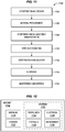
FIG. 8A is a flowchart illustrating amethod 800 for using additive manufacturing to fabricate a septum of an acoustic cell in an illustrative embodiment. The steps ofmethod 800 are described with reference to fusedfilament fabrication system 700 ofFIG. 7 , but those skilled in the art will appreciate thatmethod 800 may be performed in other additive manufacturing environments as desired. The steps of the flowcharts described herein are not all inclusive and may include other steps not shown. The steps described herein may also be performed in an alternative order. Furthermore, these steps may be performed by a machine operating in accordance with a Numerical Control (NC) program, such as theNC program 712 ofFIG. 7 in order to engage in an automatically controlled process. - Controller 710 directs
actuator 720 to movenozzle 734 into position above a location where fabrication will initiate forseptum 100. Controller 710 directsheater 732 to proceed with heating a material (e.g., thermoplastic 742) to a melting temperature (e.g., 720° Fahrenheit), resulting in a molten material (e.g., molten thermoplastic 750) (step 802). Controller 710 loads theNC program 712, and proceeds to acquire fabrication instructions forseptum 100 indicating how fusedfilament fabrication system 700 is moved, where molten material should be deposited, and how much molten material is deposited (step 803). Controller 710 further directsactuator 720 andnozzle 734 to actively deposit molten material to initiate fabrication ofseptum 100. This includes depositing molten material that formslower chamber 150 ofseptum 100 which extends vertically upward and includesentry 132 having perimeter 140 (step 804). - With
lower chamber 150 fabricated, controller 710 proceeds todirect actuator 720 andnozzle 734 in depositing additional amounts of molten material. Specifically, controller 710 directsactuator 720 andnozzle 734 to deposit a layer of the molten material as a filament at entry 132 (e.g., a filament that followsperimeter 140 around entry 132) (step 806). The filament forms a shape that is hollow and bounded. Further filamentous layers are added, and each layer includes overhangs with respect to vertically adjacent layers. The process continues, iteratively depositing additional layers. If controller 710 determines that not alllayers 124 have been deposited (step 808), then controller 710 may directactuator 720 andnozzle 734 to deposit an additional layer by returning to step 806. -
Layers 124 solidify (e.g., cool), formingopenings 230 between vertically adjacent layers at locations ofoverhangs 290 asoverhangs 290 droop. Theseopenings 230 lead intolower chamber 150 ofseptum 100. For example, a filament of eachlayer 124 may be deposited with slight overhangs that proceed beyond the filaments oflayers 124 that are vertically adjacent (e.g., touching) in order to formopenings 230. In such an embodiment, each filament may include cantilevered protrusions deposited onto a location without underlying support, and these protrusions droop downward after the filament is deposited in order to formopenings 230.Stack 120 may comprise any suitable number of layers, such as one hundred layers or more. - The unique geometry of
stack 120 allows foropenings 230 to be placed withinseptum 100 via additive manufacturing techniques, which makesseptum 100 viable to enable controlled flow of acoustic energy throughupper chamber 420 andlower chamber 150. Furthermore, becauseseptum 100 is fabricated via additive manufacturing techniques, anacoustic panel 500 may be fabricated as one integral piece. This facilitates automated manufacturing of acoustic panels, thereby reducing cost. Furthermore, a remaining portion of an acoustic cell (e.g.,walls 410, facesheet 430) may also be fabricated via the same additive manufacturing process as used to fabricateseptum 100. This allows for the acoustic cell and its corresponding septum to be fabricated at the same time. - Using the septa described above, a method may be performed for an acoustic cell. This is illustrated with regard to
method 850 ofFIG. 8B . The method may include, for example, receiving airflow across a facesheet of a panel comprising multiple acoustic cells (step 852). The method also includes directing the airflow into cells of the acoustic panel via the facesheet (step 854), and vibrating the septa of the cells in a manner that provides control of acoustic energy and phase (step 856). - Calibrated control of acoustic energy via acoustic cells may be modeled via a circuit diagram. Specifically, utilizing the circuit diagram 900 of
FIG. 9 , an impedance of an entire acoustic panel can be calibrated. In such an embodiment, R1 and R2 represent resistors of the Resistive Inductive Capacitive (RLC) circuit ofFIG. 9 , C1 and C2 represent capacitors of the RLC circuit ofFIG. 9 , and L1 represents an inductor of the RLC circuit. From these features, Z1, Z2, and Z_system (representing impedance of various portions of the circuit) may be calculated. Specifically, R1 corresponds to a resistance of acoustic energy provided by a facesheet of the panel. L1 corresponds to impedance of (mass) air flow caused by the shape, number, and/or size of openings in the facesheet (and may, for example, be calibrated by adjusting a Percent Open Area (POA) for the facesheet). Continuing onward, C1 corresponds to a volume of air capacitance between a septum and the facesheet, while C2 corresponds to a volume of air capacitance between the septum and a backing sheet. R2 is defined by resistance of acoustic energy caused by travel through the septum. Z1 may be calibrated by varying R1, L1, and C1 as desired. In a similar fashion, Z2 may be calibrated based on values for R2 and C2. In this manner, Z_system for the entirety of the acoustic panel may rapidly be calculated. For example, the percent open area of afacesheet 430 may be chosen to provide a specific level of resistance to airflow intoacoustic cell 400 that resists/dampens a selected frequency (or frequencies) of acoustic energy. Meanwhile, a thickness offacesheet 430 may provide an inductive response that regulates mass flow of air intoacoustic cell 400. Aseptum 100 withinacoustic cell 400 may define capacitance (energy storage) of the cell, and further may resist airflow. Thus, volumes of free space withinacoustic cell 400, as well as the total volume ofacoustic cell 400 may be considered and programmatically controlled in a double Degree of Freedom (DOF) system to control the acoustic properties ofacoustic cell 400 and control/damp specific frequencies. This technique may be particularly helpful in scenarios where specific frequencies of noise from an aircraft engine are perceptible to passengers of the aircraft and are known to cause discomfort to passengers of the aircraft. - In the following examples, additional processes, systems, and methods are described in the context of an acoustic panel with septa fabricated via additive manufacturing processes.
-
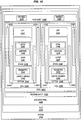
FIG. 10 is a block diagram of anacoustic panel 1020 mounted at an engine 1000 (e.g., an engine of an aircraft) in an illustrative embodiment. In this embodiment,inlet 1010 ofengine 1000 includes one or moreacoustic panels 1020 to control acoustic energy.Acoustic panel 1020 includes backing sheet 1022, which forms a base/floor forcore 1024 ofacoustic panel 1020.Core 1024 includes a number ofacoustic cells 1030. Eachacoustic cell 1030 includeswalls 1032, as well asseptum 1040. Eachseptum 1040 includeswalls 1044 defining alower chamber 1042 having aperimeter 1043.Stack 1046 is disposed atopperimeter 1043, and includeslayers 1047. Eachlayer 1047 includesvertices 1048, and may include aseam 1049.Cap 1041 terminatesseptum 1040. A facesheet 1026 withopenings 1028 covers eachacoustic cell 1030, enabling acoustic energy to pass intoacoustic cells 1030 for acoustic control. - Referring more particularly to the drawings, embodiments of the disclosure may be described in the context of an aircraft manufacturing and service method 1100 as shown in
FIG. 11 and anaircraft 1102 as shown inFIG. 12 . During pre-production, illustrative method 1100 may include specification anddesign 1104 of theaircraft 1102 andmaterial procurement 1106. During production, component andsubassembly manufacturing 1108 andsystem integration 1110 of theaircraft 1102 takes place. Thereafter, theaircraft 1102 may go through certification anddelivery 1112 to be placed inservice 1114. While in service by a customer, theaircraft 1102 is scheduled for routine maintenance and service 1116 (which may also include modification, reconfiguration, refurbishment, and so on). Apparatus and methods embodied herein may be employed during any one or more suitable stages of the production and service method 1100 (e.g., specification anddesign 1104,material procurement 1106, component andsubassembly manufacturing 1108,system integration 1110, certification anddelivery 1112,service 1114, maintenance and service 1116) and/or any suitable component of aircraft 1102 (e.g.,airframe 1118,systems 1120, interior 1122,propulsion 1124, electrical 1126, hydraulic 1128, environmental 1130). - Each of the processes of method 1100 may be performed or carried out by a system integrator, a third party, and/or an operator (e.g., a customer). For the purposes of this description, a system integrator may include without limitation any number of aircraft manufacturers and major-system subcontractors; a third party may include without limitation any number of vendors, subcontractors, and suppliers; and an operator may be an airline, leasing company, military entity, service organization, and so on.
- As shown in
FIG. 12 , theaircraft 1102 produced by illustrative method 1100 may include anairframe 1118 with a plurality ofsystems 1120 and an interior 1122. Examples of high-level systems 1120 include one or more of apropulsion system 1124, anelectrical system 1126, ahydraulic system 1128, and anenvironmental system 1130. Any number of other systems may be included. Although an aerospace example is shown, the principles of the invention may be applied to other industries, such as but not limited to the automotive, agricultural, marine, appliance, and similar industries. - As already mentioned above, apparatus and methods embodied herein may be employed during any one or more of the stages of the production and service method 1100. For example, components or subassemblies corresponding to
production stage 1108 may be fabricated or manufactured in a manner similar to components or subassemblies produced while theaircraft 1102 is in service. Also, one or more apparatus embodiments, method embodiments, or a combination thereof may be utilized during theproduction stages aircraft 1102. Similarly, one or more of apparatus embodiments, method embodiments, or a combination thereof may be utilized while theaircraft 1102 is in service, for example and without limitation, to maintenance andservice 1116. For example, the techniques and systems described herein may be used forsteps airframe 1118 and/or interior 1122. These techniques and systems may even be utilized forsystems 1120, including forexample propulsion 1124, electrical 1126, hydraulic 1128, and/or environmental 1130. - In one embodiment, an
acoustic panel 500 is coupled with a portion ofairframe 1118, and is manufactured during component andsubassembly manufacturing 1108. Theacoustic panel 500 may continue inservice 1114 until wear renders theacoustic panel 500 unusable. Then, in maintenance andservice 1116, theacoustic panel 500 may be discarded and replaced with a newly manufactured part. Inventive components and methods may be used throughout component andsubassembly manufacturing 1108 to manufacture another ofacoustic panels 500 and septa for thoseacoustic panels 500. - Any of the various control elements (e.g., electrical or electronic components) shown in the figures or described herein may be implemented as hardware, a processor implementing software, a processor implementing firmware, or some combination of these. For example, an element may be implemented as dedicated hardware. Dedicated hardware elements may be referred to as "processors", "controllers", or some similar terminology. When provided by a processor, the functions may be provided by a single dedicated processor, by a single shared processor, or by a plurality of individual processors, some of which may be shared. Moreover, explicit use of the term "processor" or "controller" should not be construed to refer exclusively to hardware capable of executing software, and may implicitly include, without limitation, digital signal processor (DSP) hardware, a network processor, application specific integrated circuit (ASIC) or other circuitry, field programmable gate array (FPGA), read only memory (ROM) for storing software, random access memory (RAM), non-volatile storage, logic, or some other physical hardware component or module.
- Also, a control element may be implemented as instructions executable by a processor or a computer to perform the functions of the element. Some examples of instructions are software, program code, and firmware. The instructions are operational when executed by the processor to direct the processor to perform the functions of the element. The instructions may be stored on storage devices that are readable by the processor. Some examples of the storage devices are digital or solid-state memories, magnetic storage media such as a magnetic disks and magnetic tapes, hard drives, or optically readable digital data storage media.
- The present method is also referred to in the following clauses which are not to be confused with the claims.
- A1. A method comprising:
fabricating a septum of a cell of an acoustic panel, by:- heating a material into a molten material (802);
- depositing the molten material to form a lower chamber of the septum that extends vertically upwards and includes an entry (804);
- iteratively depositing layers of the molten material, each layer comprising a filament at the entry that includes overhangs with respect to vertically adjacent layers (806-808); and forming openings at locations of the overhangs (810).
- A2. There is also provided, the method of paragraph A1 wherein:
depositing layers comprises depositing a filament at one of the layers that extends beyond filaments of adjacent layers to form the overhangs. - A3. There is also provided, the method of paragraph A1 wherein:
depositing layers is performed such that each of the filaments is deposited as a multi-pointed star shape having vertices comprising recesses and protrusions, wherein recesses in each of the layers align with protrusions of vertically adjacent layers to form the openings. - A4. There is also provided, the method of paragraph A3 further comprising:
drooping each protrusion downward after it is deposited. - A5. There is also provided, the method of paragraph A1 wherein:
- iteratively depositing the layers results in at least fifty layers, and
- each layer forms at least ten openings with vertically adjacent layers.
- A6. There is also provided, the method of paragraph A1 wherein:
fabricating the septum is performed via fused filament fabrication. - A7. There is also provided, the method of paragraph A1 wherein:
forming a seam at each layer, wherein seams of vertically adjacent layers are deposited atop each other. - A8. There is also provided, the method of paragraph A1 wherein:
the openings have diameters between one ten thousandth of an inch and one thousandth of an inch in diameter. - A9. There is also provided, the method of paragraph A1 further comprising:
depositing molten material to form a solid cap of material atop the layers. - A10. There is also provided, the method of paragraph A1 further comprising:
depositing molten material to form a solid wall of material that surrounds the layers and forms an upper chamber of an acoustic cell. - A11. A portion of an aircraft assembled according to the method of paragraph A1. According to a further aspect of the present medium, there is provided:
- B1. A non-transitory computer readable medium embodying programmed instructions which, when executed by a processor, are operable for performing a method comprising:
fabricating a septum of a cell of an acoustic panel, by:- heating a material into a molten material (802);
- depositing the molten material to form a lower chamber of the septum that extends vertically upwards and includes an entry (804);
- iteratively depositing layers of the molten material, each layer comprising a filament at the entry that includes overhangs with respect to vertically adjacent layers (806-808); and forming openings at locations of the overhangs (810).
- B2. There is also provided, the medium of paragraph B1 wherein:
depositing layers comprises depositing a filament at one of the layers that extends beyond filaments of adjacent layers to form the overhangs. - B3. There is also provided, the medium of paragraph B1 wherein:
depositing layers is performed such that each of the filaments is deposited as a multi-pointed star shape having vertices comprising recesses and protrusions, wherein recesses in each of the layers align with protrusions of vertically adjacent layers to form the openings. - B4. There is also provided, the medium of paragraph B3 wherein the method further comprises:
drooping each protrusion downward after it is deposited. - B5. There is also provided, the medium of paragraph B1 wherein:
- iteratively depositing the layers results in at least fifty layers, and
- each layer forms at least ten openings with vertically adjacent layers.
- B6. There is also provided, the medium of paragraph B1 wherein:
fabricating the septum is performed via fused filament fabrication. - B7. There is also provided, the medium of paragraph B1 wherein the method further comprises:
forming a seam at each layer, wherein seams of vertically adjacent layers are deposited atop each other. - According to a further aspect of the present apparatus, there is provided:
- C1. An apparatus comprising:
a septum (100) of an acoustic cell (400), comprising:- a lower chamber (150) that extends vertically upwards and includes an entry (132);
- a stack (120) comprising layers (124) of material disposed atop the entry of the lower chamber, each layer of the stack comprises a filament (216) at the entry and includes overhangs (290) with respect to vertically adjacent layers; and
- openings (230) that are disposed between the layers at locations of the overhangs and that result from the overhangs extending beyond adjacent layers.
- C2. There is also provided, the apparatus of paragraph C1 wherein:
each layer of the stack is between one thousandth of an inch and one hundredth of an inch thick. - C3. There is also provided, the apparatus of paragraph C1 wherein:
the material comprises Poly Aryl Ether Ketone (PAEK). - C4. There is also provided, the apparatus of paragraph C1 wherein:
each layer in the stack is a multi-pointed star shape having vertices (260) that comprise protrusions (224) and recesses (212), and recesses in each layer align with protrusions of adjacent layers. - C5. There is also provided, the apparatus of paragraph C1 further comprising:
a seam (240) at each layer of the stack that protrudes into a corresponding hollow portion (250) of each layer of the stack, wherein seams of the layers of the stack are aligned atop each other. - C6. There is also provided, the apparatus of paragraph C1 further comprising:
a solid wall (410) of material that surrounds the stack and forms an upper chamber (420) of an acoustic cell (400). - C7. There is also provided, the apparatus of paragraph C1 wherein:
the openings are between one ten thousandth of an inch and one thousandth of an inch in diameter. - C8. There is also provided, the apparatus of paragraph C1 further comprising:
a solid cap (110) of material atop the stack. - C9. There is also provided, the apparatus of paragraph C1 wherein:
the openings perform acoustic control by causing the septum to vibrate in a manner that provides control of acoustic phase and energy. - C10. Fabricating a portion of an aircraft using the apparatus of paragraph C1.
- Although specific embodiments are described herein, the scope of the disclosure is not limited to those specific embodiments. The scope of the disclosure is defined by the following claims and any equivalents thereof.
Claims (15)
- A method comprising:fabricating a septum of a cell of an acoustic panel, by:heating a material into a molten material (802);depositing the molten material to form a lower chamber of the septum that extends vertically upwards and includes an entry (804);iteratively depositing layers of the molten material, each layer comprising a filament at the entry that includes overhangs with respect to vertically adjacent layers (806-808); andforming openings at locations of the overhangs (810).
- The method of claim 1 wherein:depositing layers comprises depositing a filament at one of the layers that extends beyond filaments of adjacent layers to form the overhangs.
- The method of claim 1 or claim 2, wherein:depositing layers is performed such that each of the filaments is deposited as a multi-pointed star shape having vertices comprising recesses and protrusions, wherein recesses in each of the layers align with protrusions of vertically adjacent layers to form the openings.
- The method of claim 3 further comprising:drooping each protrusion downward after it is deposited.
- The method of any one of the preceding claims wherein:iteratively depositing the layers results in at least fifty layers, andeach layer forms at least ten openings with vertically adjacent layers.
- The method of any one of the preceding claims wherein:forming a seam at each layer, wherein seams of vertically adjacent layers are deposited atop each other.
- The method of any one of the preceding claims wherein:the openings have diameters between one ten thousandth of an inch and one thousandth of an inch in diameter.
- The method of any one of the preceding claims further comprising:depositing molten material to form a solid wall of material that surrounds the layers and forms an upper chamber of an acoustic cell.
- An apparatus comprising:a septum (100) of an acoustic cell (400), comprising:a lower chamber (150) that extends vertically upwards and includes an entry (132);a stack (120) comprising layers (124) of material disposed atop the entry of the lower chamber, each layer of the stack comprises a filament (216) at the entry and includes overhangs (290) with respect to vertically adjacent layers; andopenings (230) that are disposed between the layers at locations of the overhangs and that result from the overhangs extending beyond adjacent layers.
- The apparatus of claim 9 wherein:each layer of the stack is between one thousandth of an inch and one hundredth of an inch thick.
- The apparatus of claim 9 or claim 10 wherein:each layer in the stack is a multi-pointed star shape having vertices (260) that comprise protrusions (224) and recesses (212), and recesses in each layer align with protrusions of adjacent layers.
- The apparatus of any one of claims 9 to 11 further comprising:a seam (240) at each layer of the stack that protrudes into a corresponding hollow portion (250) of each layer of the stack, wherein seams of the layers of the stack are aligned atop each other.
- The apparatus of claim 9 further comprising:a solid wall (410) of material that surrounds the stack and forms an upper chamber (420) of an acoustic cell (400).
- The apparatus of any one of claims 9 to 12 wherein:the openings are between one ten thousandth of an inch and one thousandth of an inch in diameter.
- The apparatus of any one of claims 9 to 14 wherein:the openings perform acoustic control by causing the septum to vibrate in a manner that provides control of acoustic phase and energy.
Applications Claiming Priority (1)
| Application Number | Priority Date | Filing Date | Title |
|---|---|---|---|
| US15/836,034 US11034460B2 (en) | 2017-12-08 | 2017-12-08 | Additively manufactured septa for acoustic panels |
Publications (2)
| Publication Number | Publication Date |
|---|---|
| EP3496088A1 true EP3496088A1 (en) | 2019-06-12 |
| EP3496088B1 EP3496088B1 (en) | 2023-04-12 |
Family
ID=63637661
Family Applications (1)
| Application Number | Title | Priority Date | Filing Date |
|---|---|---|---|
| EP18194173.3A Active EP3496088B1 (en) | 2017-12-08 | 2018-09-13 | Additively manufactured septa for acoustic panels |
Country Status (5)
| Country | Link |
|---|---|
| US (2) | US11034460B2 (en) |
| EP (1) | EP3496088B1 (en) |
| JP (1) | JP7202856B2 (en) |
| KR (1) | KR102665618B1 (en) |
| CN (1) | CN109896041B (en) |
Cited By (1)
| Publication number | Priority date | Publication date | Assignee | Title |
|---|---|---|---|---|
| WO2021209344A1 (en) * | 2020-04-16 | 2021-10-21 | Signify Holding B.V. | Luminaire with texture perforation |
Families Citing this family (12)
| Publication number | Priority date | Publication date | Assignee | Title |
|---|---|---|---|---|
| US10253195B2 (en) | 2014-11-24 | 2019-04-09 | Ppg Industries Ohio, Inc. | Coreactive materials and methods for three-dimensional printing |
| US10434704B2 (en) | 2017-08-18 | 2019-10-08 | Ppg Industries Ohio, Inc. | Additive manufacturing using polyurea materials |
| US12384097B2 (en) | 2017-08-18 | 2025-08-12 | Ppg Industries Ohio, Inc. | Additive manufacturing using reactive compositions |
| US11034460B2 (en) * | 2017-12-08 | 2021-06-15 | The Boeing Company | Additively manufactured septa for acoustic panels |
| KR20210124439A (en) | 2019-02-11 | 2021-10-14 | 피피지 인더스트리즈 오하이오 인코포레이티드 | 3D printing of sealing caps |
| CN113710481A (en) | 2019-02-11 | 2021-11-26 | Ppg工业俄亥俄公司 | Multilayer system and method for producing a multilayer system |
| EP3924187A1 (en) | 2019-02-11 | 2021-12-22 | PPG Industries Ohio, Inc. | Elastomeric compositions and methods of use |
| MX2021009606A (en) | 2019-02-11 | 2021-11-12 | Ppg Ind Ohio Inc | Methods of making chemically resistant sealing components. |
| EP3882003A1 (en) * | 2020-03-16 | 2021-09-22 | Signify Holding B.V. | 3d printed item with surface with opening |
| PL244140B1 (en) * | 2021-06-28 | 2023-12-04 | 3Dartech Spolka Z Ograniczona Odpowiedzialnoscia | Method of producing a rigid acoustic absorber with variable artistic form using 3D printing technology and a rigid acoustic absorber with variable artistic form produced in this way |
| US12006874B2 (en) | 2022-02-14 | 2024-06-11 | Rolls-Royce Corporation | 3D printed acoustic panel with lattice structure support layer |
| US12136408B2 (en) | 2022-04-29 | 2024-11-05 | Rolls-Royce Corporation | Acoustic panel with 3D printed cell structure support layer |
Citations (4)
| Publication number | Priority date | Publication date | Assignee | Title |
|---|---|---|---|---|
| EP2389501A1 (en) * | 2009-01-23 | 2011-11-30 | Dresser-Rand Company | Fluid-carrying conduit and method with noise attenuation |
| US20150041248A1 (en) * | 2013-08-12 | 2015-02-12 | Hexcel Corporation | Multi-sectional acoustic septum |
| US20170107909A1 (en) * | 2015-10-20 | 2017-04-20 | Airbus Helicopters | Gas ejection duct with acoustic treatment, an aircraft, and a method of fabricating such a duct |
| WO2019018252A1 (en) * | 2017-07-21 | 2019-01-24 | Dresser-Rand Company | Acoustic attenuator for a turbomachine and methodology for additively manufacturing said acoustic attenuator |
Family Cites Families (49)
| Publication number | Priority date | Publication date | Assignee | Title |
|---|---|---|---|---|
| US4530418A (en) * | 1982-06-01 | 1985-07-23 | Currie Neil L | Automotive exhaust system |
| JPS5978409U (en) * | 1982-11-16 | 1984-05-28 | 日本板硝子株式会社 | Soundproof frame wall structure |
| US5491310A (en) * | 1990-08-16 | 1996-02-13 | Jen; Wang H. | Acoustic board |
| US5185504A (en) * | 1992-06-30 | 1993-02-09 | Jen Wang H | Acoustic board |
| US5004070A (en) * | 1990-08-16 | 1991-04-02 | Wang Hong Jen | Acoustic board |
| CH682553A5 (en) * | 1990-09-03 | 1993-10-15 | Matec Holding | Sound-insulating and sound-insulating composite. |
| US5997985A (en) * | 1998-09-10 | 1999-12-07 | Northrop Grumman Corporation | Method of forming acoustic attenuation chambers using laser processing of multi-layered polymer films |
| FR2815900B1 (en) * | 2000-10-31 | 2003-07-18 | Eads Airbus Sa | NOISE REDUCING SANDWICH PANEL, ESPECIALLY FOR AN AIRCRAFT TURBOREACTOR |
| US6457554B1 (en) * | 2001-03-15 | 2002-10-01 | Samw Hong Jen Wang | Acoustic absorber for absorbing noises in buildings |
| FR2841031B1 (en) * | 2002-06-17 | 2005-02-11 | Hurel Hispano Le Havre | PROCESS FOR PRODUCING A DOUBLE RESONATOR ACOUSTIC PANEL |
| FR2862798B1 (en) * | 2003-11-21 | 2006-03-17 | Snecma Moteurs | INSONORIZING BALL PANEL AND METHOD OF MAKING SAME |
| AU2006223685B2 (en) * | 2005-03-18 | 2010-12-09 | Tumane Enterprises Limited | A sound dampening flow channel device |
| DE102005013311A1 (en) * | 2005-03-22 | 2006-10-05 | Federal-Mogul Sealing Systems Gmbh | Shielding element for motor vehicles |
| US7451855B2 (en) * | 2007-01-09 | 2008-11-18 | Samw Hong Jen Wang | Acoustic absorbing device |
| US9890091B2 (en) * | 2007-03-22 | 2018-02-13 | Ronald D Jones | Persistent vortex generating high regression rate solid fuel grain for a hybrid rocket engine and method for manufacturing same |
| GB0919934D0 (en) * | 2009-11-16 | 2009-12-30 | Sunamp Ltd | Energy storage systems |
| US8047329B1 (en) * | 2010-08-13 | 2011-11-01 | Rohr, Inc. | System and method for noise suppression |
| US9604428B2 (en) * | 2010-08-24 | 2017-03-28 | James Walker | Ventilated structural panels and method of construction with ventilated structural panels |
| US10119589B2 (en) * | 2011-08-17 | 2018-11-06 | Hrl Laboratories, Llc | Microlattice damping material and method for repeatable energy absorption |
| FR2980775B1 (en) * | 2011-10-03 | 2014-07-11 | Airbus Operations Sas | AIRCRAFT NACELLE COMPRISING A PANEL FOR ACOUSTIC TREATMENT INTEGRATING HOT AIR CHANNELS AND AT LEAST ONE STABILIZING CHAMBER |
| US9321241B2 (en) * | 2012-05-11 | 2016-04-26 | The Boeing Company | Ventilated aero-structures, aircraft and associated methods |
| US20170267315A1 (en) * | 2012-05-24 | 2017-09-21 | Global Ip Holdings, Llc | Marine decking with sandwich-type construction and method of making same |
| US9027706B2 (en) * | 2013-02-11 | 2015-05-12 | Federal-Mogul Powertrain, Inc. | Enhanced, lightweight acoustic scrim barrier |
| WO2014165167A1 (en) * | 2013-03-12 | 2014-10-09 | Kline Bret E | System and method for using adsorbent/absorbent in loading, storing, delivering, and retrieving gases, fluids, and liquids |
| JP2015006650A (en) * | 2013-06-26 | 2015-01-15 | 須知 晃一 | Manufacturing method and constituent materials of cell structure structure cell composite objects |
| WO2015042422A1 (en) * | 2013-09-19 | 2015-03-26 | Markforged, Inc. | Methods for fiber reinforced additive manufacturing |
| US9693166B2 (en) * | 2014-06-24 | 2017-06-27 | The Boeing Company | Automated production of acoustic structures |
| JP2016013671A (en) * | 2014-07-03 | 2016-01-28 | キヤノン株式会社 | Convexoconcave formation device and convexoconcave formation method |
| US10563578B2 (en) * | 2015-02-18 | 2020-02-18 | Mra Systems, Llc | Acoustic liners and method of shaping an inlet of an acoustic liner |
| WO2016195974A1 (en) * | 2015-06-02 | 2016-12-08 | Apex Biomedical Company, Llc | Energy-absorbing structure with defined multi-phasic crush properties |
| CN105034361A (en) * | 2015-06-15 | 2015-11-11 | 清华大学 | Honeycomb core sandwich and preparation method thereof |
| US9330651B1 (en) * | 2015-07-16 | 2016-05-03 | Hong Jen Wang | Acoustic absorbing combination |
| US9607598B2 (en) * | 2015-08-17 | 2017-03-28 | The Boeing Company | Acoustic sandwich panel and method |
| US10232549B2 (en) * | 2015-09-10 | 2019-03-19 | The Boeing Company | Geometric sound absorption via additive manufacturing |
| EP3541092B1 (en) * | 2015-09-30 | 2021-08-11 | Apple Inc. | Earbud case with charging system |
| US9732677B1 (en) * | 2016-05-12 | 2017-08-15 | Rohr, Inc. | Broadband acoustic panels coupled with large secondary cavities to attenuate low frequencies |
| CN206171353U (en) * | 2016-11-17 | 2017-05-17 | 上海凯密科实业有限公司 | Fine heat and sound isolation pad of engine compartment aluminium foil glass |
| US10032445B1 (en) * | 2016-12-13 | 2018-07-24 | Northrop Grumman Systems Corporation | Honeycomb unit cell acoustic metamaterial with in situ buttresses for tuned acoustic frequency attenuation |
| US10369763B2 (en) * | 2017-04-19 | 2019-08-06 | The Boeing Company | Segmented acoustic insert |
| US10479520B2 (en) * | 2017-05-25 | 2019-11-19 | The Boeing Company | Composite structure assembly having an interconnected layered core |
| US10577117B2 (en) * | 2017-08-04 | 2020-03-03 | Hexcel Corporation | Angled acoustic honeycomb |
| US10851713B2 (en) * | 2017-08-29 | 2020-12-01 | Mra Systems, Llc. | Acoustic liner having internal structure |
| US10783869B2 (en) * | 2017-09-12 | 2020-09-22 | Honeywell International Inc. | Cell structure for use in an acoustic panel, and methods of producing the same |
| US10808399B2 (en) * | 2017-10-12 | 2020-10-20 | Honeywell International Inc. | Enhanced acoustic cell and enhanced acoustic panel, and methods of producing the same |
| WO2019110939A1 (en) * | 2017-12-06 | 2019-06-13 | Safran Aircraft Engines | Method for manufacturing an ordered network of acoustic channels made of abradable material |
| US11034460B2 (en) * | 2017-12-08 | 2021-06-15 | The Boeing Company | Additively manufactured septa for acoustic panels |
| US10836502B2 (en) * | 2017-12-15 | 2020-11-17 | The Boeing Company | Wave-shaped acoustic insert and core |
| US11415055B2 (en) * | 2020-03-09 | 2022-08-16 | Honeywell International Inc. | Alternating helicoid cell structure and methods of producing the same |
| US11668236B2 (en) * | 2020-07-24 | 2023-06-06 | General Electric Company | Acoustic liners with low-frequency sound wave attenuating features |
-
2017
- 2017-12-08 US US15/836,034 patent/US11034460B2/en active Active
-
2018
- 2018-09-13 EP EP18194173.3A patent/EP3496088B1/en active Active
- 2018-10-25 CN CN201811247169.1A patent/CN109896041B/en active Active
- 2018-11-21 JP JP2018218243A patent/JP7202856B2/en active Active
- 2018-11-29 KR KR1020180150443A patent/KR102665618B1/en active Active
-
2021
- 2021-05-10 US US17/315,783 patent/US11891162B2/en active Active
Patent Citations (4)
| Publication number | Priority date | Publication date | Assignee | Title |
|---|---|---|---|---|
| EP2389501A1 (en) * | 2009-01-23 | 2011-11-30 | Dresser-Rand Company | Fluid-carrying conduit and method with noise attenuation |
| US20150041248A1 (en) * | 2013-08-12 | 2015-02-12 | Hexcel Corporation | Multi-sectional acoustic septum |
| US20170107909A1 (en) * | 2015-10-20 | 2017-04-20 | Airbus Helicopters | Gas ejection duct with acoustic treatment, an aircraft, and a method of fabricating such a duct |
| WO2019018252A1 (en) * | 2017-07-21 | 2019-01-24 | Dresser-Rand Company | Acoustic attenuator for a turbomachine and methodology for additively manufacturing said acoustic attenuator |
Cited By (1)
| Publication number | Priority date | Publication date | Assignee | Title |
|---|---|---|---|---|
| WO2021209344A1 (en) * | 2020-04-16 | 2021-10-21 | Signify Holding B.V. | Luminaire with texture perforation |
Also Published As
| Publication number | Publication date |
|---|---|
| KR20190068436A (en) | 2019-06-18 |
| CN109896041A (en) | 2019-06-18 |
| US11034460B2 (en) | 2021-06-15 |
| KR102665618B1 (en) | 2024-05-27 |
| CN109896041B (en) | 2023-08-15 |
| EP3496088B1 (en) | 2023-04-12 |
| US20190176998A1 (en) | 2019-06-13 |
| JP2019109501A (en) | 2019-07-04 |
| US20220063828A1 (en) | 2022-03-03 |
| JP7202856B2 (en) | 2023-01-12 |
| US11891162B2 (en) | 2024-02-06 |
Similar Documents
| Publication | Publication Date | Title |
|---|---|---|
| US11891162B2 (en) | Additively manufactured septa for acoustic panels | |
| CA3155539C (en) | Acoustic paneling | |
| US10443496B2 (en) | Acoustic paneling | |
| US10363726B2 (en) | Septumization of honeycomb sandwiches | |
| JP6906017B2 (en) | Formation of septum for cellular core | |
| JP6495275B2 (en) | Composite laminates with hole patterns created by controlled fiber placement | |
| Eiliat et al. | Visualizing, analyzing, and managing voids in the material extrusion process | |
| CN110856977A (en) | Modeling table, three-dimensional modeling device and control method of three-dimensional modeling device | |
| JP2021005863A (en) | Additively manufactured radio frequency filter | |
| Sajjad et al. | Investigating the impacts of heterogeneous infills on structural strength of 3D printed parts | |
| CN111319316B (en) | Composite component, method and system for forming a composite component | |
| NL2018888B1 (en) | Acoustic paneling | |
| EP4450282A2 (en) | Cellular core for aircraft acoustic panel and method of manufacture | |
| US20220194017A1 (en) | Methods and apparatus for induction welding | |
| US20250121957A1 (en) | Additively Manufactured Aerospace Panels and Methods | |
| TR2023018333Y (en) | A Powder Bed Additive Manufacturing System. |
Legal Events
| Date | Code | Title | Description |
|---|---|---|---|
| PUAI | Public reference made under article 153(3) epc to a published international application that has entered the european phase |
Free format text: ORIGINAL CODE: 0009012 |
|
| STAA | Information on the status of an ep patent application or granted ep patent |
Free format text: STATUS: REQUEST FOR EXAMINATION WAS MADE |
|
| 17P | Request for examination filed |
Effective date: 20180913 |
|
| AK | Designated contracting states |
Kind code of ref document: A1 Designated state(s): AL AT BE BG CH CY CZ DE DK EE ES FI FR GB GR HR HU IE IS IT LI LT LU LV MC MK MT NL NO PL PT RO RS SE SI SK SM TR |
|
| AX | Request for extension of the european patent |
Extension state: BA ME |
|
| RBV | Designated contracting states (corrected) |
Designated state(s): AL AT BE BG CH CY CZ DE DK EE ES FI FR GB GR HR HU IE IS IT LI LT LU LV MC MK MT NL NO PL PT RO RS SE SI SK SM TR |
|
| STAA | Information on the status of an ep patent application or granted ep patent |
Free format text: STATUS: EXAMINATION IS IN PROGRESS |
|
| 17Q | First examination report despatched |
Effective date: 20210406 |
|
| RIC1 | Information provided on ipc code assigned before grant |
Ipc: F02C 7/045 20060101ALN20220914BHEP Ipc: F01N 1/02 20060101ALN20220914BHEP Ipc: B64D 33/02 20060101ALN20220914BHEP Ipc: B33Y 10/00 20150101ALI20220914BHEP Ipc: B29D 99/00 20100101ALI20220914BHEP Ipc: B64C 1/40 20060101ALI20220914BHEP Ipc: B29C 64/106 20170101ALI20220914BHEP Ipc: B33Y 80/00 20150101ALI20220914BHEP Ipc: G10K 11/172 20060101AFI20220914BHEP |
|
| GRAP | Despatch of communication of intention to grant a patent |
Free format text: ORIGINAL CODE: EPIDOSNIGR1 |
|
| STAA | Information on the status of an ep patent application or granted ep patent |
Free format text: STATUS: GRANT OF PATENT IS INTENDED |
|
| RIC1 | Information provided on ipc code assigned before grant |
Ipc: F02C 7/045 20060101ALN20221026BHEP Ipc: F01N 1/02 20060101ALN20221026BHEP Ipc: B64D 33/02 20060101ALN20221026BHEP Ipc: B33Y 10/00 20150101ALI20221026BHEP Ipc: B29D 99/00 20100101ALI20221026BHEP Ipc: B64C 1/40 20060101ALI20221026BHEP Ipc: B29C 64/106 20170101ALI20221026BHEP Ipc: B33Y 80/00 20150101ALI20221026BHEP Ipc: G10K 11/172 20060101AFI20221026BHEP |
|
| INTG | Intention to grant announced |
Effective date: 20221115 |
|
| GRAS | Grant fee paid |
Free format text: ORIGINAL CODE: EPIDOSNIGR3 |
|
| GRAA | (expected) grant |
Free format text: ORIGINAL CODE: 0009210 |
|
| STAA | Information on the status of an ep patent application or granted ep patent |
Free format text: STATUS: THE PATENT HAS BEEN GRANTED |
|
| RAP3 | Party data changed (applicant data changed or rights of an application transferred) |
Owner name: THE BOEING COMPANY |
|
| AK | Designated contracting states |
Kind code of ref document: B1 Designated state(s): AL AT BE BG CH CY CZ DE DK EE ES FI FR GB GR HR HU IE IS IT LI LT LU LV MC MK MT NL NO PL PT RO RS SE SI SK SM TR |
|
| REG | Reference to a national code |
Ref country code: GB Ref legal event code: FG4D |
|
| REG | Reference to a national code |
Ref country code: CH Ref legal event code: EP |
|
| REG | Reference to a national code |
Ref country code: DE Ref legal event code: R096 Ref document number: 602018048262 Country of ref document: DE |
|
| REG | Reference to a national code |
Ref country code: IE Ref legal event code: FG4D |
|
| REG | Reference to a national code |
Ref country code: AT Ref legal event code: REF Ref document number: 1560229 Country of ref document: AT Kind code of ref document: T Effective date: 20230515 |
|
| P01 | Opt-out of the competence of the unified patent court (upc) registered |
Effective date: 20230526 |
|
| REG | Reference to a national code |
Ref country code: LT Ref legal event code: MG9D |
|
| REG | Reference to a national code |
Ref country code: NL Ref legal event code: MP Effective date: 20230412 |
|
| REG | Reference to a national code |
Ref country code: AT Ref legal event code: MK05 Ref document number: 1560229 Country of ref document: AT Kind code of ref document: T Effective date: 20230412 |
|
| PG25 | Lapsed in a contracting state [announced via postgrant information from national office to epo] |
Ref country code: NL Free format text: LAPSE BECAUSE OF FAILURE TO SUBMIT A TRANSLATION OF THE DESCRIPTION OR TO PAY THE FEE WITHIN THE PRESCRIBED TIME-LIMIT Effective date: 20230412 |
|
| PG25 | Lapsed in a contracting state [announced via postgrant information from national office to epo] |
Ref country code: SE Free format text: LAPSE BECAUSE OF FAILURE TO SUBMIT A TRANSLATION OF THE DESCRIPTION OR TO PAY THE FEE WITHIN THE PRESCRIBED TIME-LIMIT Effective date: 20230412 Ref country code: PT Free format text: LAPSE BECAUSE OF FAILURE TO SUBMIT A TRANSLATION OF THE DESCRIPTION OR TO PAY THE FEE WITHIN THE PRESCRIBED TIME-LIMIT Effective date: 20230814 Ref country code: NO Free format text: LAPSE BECAUSE OF FAILURE TO SUBMIT A TRANSLATION OF THE DESCRIPTION OR TO PAY THE FEE WITHIN THE PRESCRIBED TIME-LIMIT Effective date: 20230712 Ref country code: ES Free format text: LAPSE BECAUSE OF FAILURE TO SUBMIT A TRANSLATION OF THE DESCRIPTION OR TO PAY THE FEE WITHIN THE PRESCRIBED TIME-LIMIT Effective date: 20230412 Ref country code: AT Free format text: LAPSE BECAUSE OF FAILURE TO SUBMIT A TRANSLATION OF THE DESCRIPTION OR TO PAY THE FEE WITHIN THE PRESCRIBED TIME-LIMIT Effective date: 20230412 |
|
| PG25 | Lapsed in a contracting state [announced via postgrant information from national office to epo] |
Ref country code: RS Free format text: LAPSE BECAUSE OF FAILURE TO SUBMIT A TRANSLATION OF THE DESCRIPTION OR TO PAY THE FEE WITHIN THE PRESCRIBED TIME-LIMIT Effective date: 20230412 Ref country code: PL Free format text: LAPSE BECAUSE OF FAILURE TO SUBMIT A TRANSLATION OF THE DESCRIPTION OR TO PAY THE FEE WITHIN THE PRESCRIBED TIME-LIMIT Effective date: 20230412 Ref country code: LV Free format text: LAPSE BECAUSE OF FAILURE TO SUBMIT A TRANSLATION OF THE DESCRIPTION OR TO PAY THE FEE WITHIN THE PRESCRIBED TIME-LIMIT Effective date: 20230412 Ref country code: LT Free format text: LAPSE BECAUSE OF FAILURE TO SUBMIT A TRANSLATION OF THE DESCRIPTION OR TO PAY THE FEE WITHIN THE PRESCRIBED TIME-LIMIT Effective date: 20230412 Ref country code: IS Free format text: LAPSE BECAUSE OF FAILURE TO SUBMIT A TRANSLATION OF THE DESCRIPTION OR TO PAY THE FEE WITHIN THE PRESCRIBED TIME-LIMIT Effective date: 20230812 Ref country code: HR Free format text: LAPSE BECAUSE OF FAILURE TO SUBMIT A TRANSLATION OF THE DESCRIPTION OR TO PAY THE FEE WITHIN THE PRESCRIBED TIME-LIMIT Effective date: 20230412 Ref country code: GR Free format text: LAPSE BECAUSE OF FAILURE TO SUBMIT A TRANSLATION OF THE DESCRIPTION OR TO PAY THE FEE WITHIN THE PRESCRIBED TIME-LIMIT Effective date: 20230713 Ref country code: AL Free format text: LAPSE BECAUSE OF FAILURE TO SUBMIT A TRANSLATION OF THE DESCRIPTION OR TO PAY THE FEE WITHIN THE PRESCRIBED TIME-LIMIT Effective date: 20230412 |
|
| PG25 | Lapsed in a contracting state [announced via postgrant information from national office to epo] |
Ref country code: FI Free format text: LAPSE BECAUSE OF FAILURE TO SUBMIT A TRANSLATION OF THE DESCRIPTION OR TO PAY THE FEE WITHIN THE PRESCRIBED TIME-LIMIT Effective date: 20230412 |
|
| REG | Reference to a national code |
Ref country code: DE Ref legal event code: R097 Ref document number: 602018048262 Country of ref document: DE |
|
| PG25 | Lapsed in a contracting state [announced via postgrant information from national office to epo] |
Ref country code: SK Free format text: LAPSE BECAUSE OF FAILURE TO SUBMIT A TRANSLATION OF THE DESCRIPTION OR TO PAY THE FEE WITHIN THE PRESCRIBED TIME-LIMIT Effective date: 20230412 |
|
| PG25 | Lapsed in a contracting state [announced via postgrant information from national office to epo] |
Ref country code: SM Free format text: LAPSE BECAUSE OF FAILURE TO SUBMIT A TRANSLATION OF THE DESCRIPTION OR TO PAY THE FEE WITHIN THE PRESCRIBED TIME-LIMIT Effective date: 20230412 Ref country code: SK Free format text: LAPSE BECAUSE OF FAILURE TO SUBMIT A TRANSLATION OF THE DESCRIPTION OR TO PAY THE FEE WITHIN THE PRESCRIBED TIME-LIMIT Effective date: 20230412 Ref country code: RO Free format text: LAPSE BECAUSE OF FAILURE TO SUBMIT A TRANSLATION OF THE DESCRIPTION OR TO PAY THE FEE WITHIN THE PRESCRIBED TIME-LIMIT Effective date: 20230412 Ref country code: EE Free format text: LAPSE BECAUSE OF FAILURE TO SUBMIT A TRANSLATION OF THE DESCRIPTION OR TO PAY THE FEE WITHIN THE PRESCRIBED TIME-LIMIT Effective date: 20230412 Ref country code: DK Free format text: LAPSE BECAUSE OF FAILURE TO SUBMIT A TRANSLATION OF THE DESCRIPTION OR TO PAY THE FEE WITHIN THE PRESCRIBED TIME-LIMIT Effective date: 20230412 Ref country code: CZ Free format text: LAPSE BECAUSE OF FAILURE TO SUBMIT A TRANSLATION OF THE DESCRIPTION OR TO PAY THE FEE WITHIN THE PRESCRIBED TIME-LIMIT Effective date: 20230412 |
|
| PLBE | No opposition filed within time limit |
Free format text: ORIGINAL CODE: 0009261 |
|
| STAA | Information on the status of an ep patent application or granted ep patent |
Free format text: STATUS: NO OPPOSITION FILED WITHIN TIME LIMIT |
|
| 26N | No opposition filed |
Effective date: 20240115 |
|
| REG | Reference to a national code |
Ref country code: CH Ref legal event code: PL |
|
| PG25 | Lapsed in a contracting state [announced via postgrant information from national office to epo] |
Ref country code: SI Free format text: LAPSE BECAUSE OF FAILURE TO SUBMIT A TRANSLATION OF THE DESCRIPTION OR TO PAY THE FEE WITHIN THE PRESCRIBED TIME-LIMIT Effective date: 20230412 |
|
| PG25 | Lapsed in a contracting state [announced via postgrant information from national office to epo] |
Ref country code: LU Free format text: LAPSE BECAUSE OF NON-PAYMENT OF DUE FEES Effective date: 20230913 |
|
| REG | Reference to a national code |
Ref country code: BE Ref legal event code: MM Effective date: 20230930 |
|
| PG25 | Lapsed in a contracting state [announced via postgrant information from national office to epo] |
Ref country code: SI Free format text: LAPSE BECAUSE OF FAILURE TO SUBMIT A TRANSLATION OF THE DESCRIPTION OR TO PAY THE FEE WITHIN THE PRESCRIBED TIME-LIMIT Effective date: 20230412 Ref country code: LU Free format text: LAPSE BECAUSE OF NON-PAYMENT OF DUE FEES Effective date: 20230913 Ref country code: IT Free format text: LAPSE BECAUSE OF FAILURE TO SUBMIT A TRANSLATION OF THE DESCRIPTION OR TO PAY THE FEE WITHIN THE PRESCRIBED TIME-LIMIT Effective date: 20230412 Ref country code: MC Free format text: LAPSE BECAUSE OF FAILURE TO SUBMIT A TRANSLATION OF THE DESCRIPTION OR TO PAY THE FEE WITHIN THE PRESCRIBED TIME-LIMIT Effective date: 20230412 |
|
| REG | Reference to a national code |
Ref country code: IE Ref legal event code: MM4A |
|
| PG25 | Lapsed in a contracting state [announced via postgrant information from national office to epo] |
Ref country code: IE Free format text: LAPSE BECAUSE OF NON-PAYMENT OF DUE FEES Effective date: 20230913 |
|
| PG25 | Lapsed in a contracting state [announced via postgrant information from national office to epo] |
Ref country code: CH Free format text: LAPSE BECAUSE OF NON-PAYMENT OF DUE FEES Effective date: 20230930 |
|
| PG25 | Lapsed in a contracting state [announced via postgrant information from national office to epo] |
Ref country code: IE Free format text: LAPSE BECAUSE OF NON-PAYMENT OF DUE FEES Effective date: 20230913 Ref country code: CH Free format text: LAPSE BECAUSE OF NON-PAYMENT OF DUE FEES Effective date: 20230930 |
|
| PG25 | Lapsed in a contracting state [announced via postgrant information from national office to epo] |
Ref country code: BE Free format text: LAPSE BECAUSE OF NON-PAYMENT OF DUE FEES Effective date: 20230930 |
|
| PG25 | Lapsed in a contracting state [announced via postgrant information from national office to epo] |
Ref country code: BG Free format text: LAPSE BECAUSE OF FAILURE TO SUBMIT A TRANSLATION OF THE DESCRIPTION OR TO PAY THE FEE WITHIN THE PRESCRIBED TIME-LIMIT Effective date: 20230412 |
|
| PG25 | Lapsed in a contracting state [announced via postgrant information from national office to epo] |
Ref country code: BG Free format text: LAPSE BECAUSE OF FAILURE TO SUBMIT A TRANSLATION OF THE DESCRIPTION OR TO PAY THE FEE WITHIN THE PRESCRIBED TIME-LIMIT Effective date: 20230412 |
|
| PG25 | Lapsed in a contracting state [announced via postgrant information from national office to epo] |
Ref country code: CY Free format text: LAPSE BECAUSE OF FAILURE TO SUBMIT A TRANSLATION OF THE DESCRIPTION OR TO PAY THE FEE WITHIN THE PRESCRIBED TIME-LIMIT; INVALID AB INITIO Effective date: 20180913 |
|
| PG25 | Lapsed in a contracting state [announced via postgrant information from national office to epo] |
Ref country code: HU Free format text: LAPSE BECAUSE OF FAILURE TO SUBMIT A TRANSLATION OF THE DESCRIPTION OR TO PAY THE FEE WITHIN THE PRESCRIBED TIME-LIMIT; INVALID AB INITIO Effective date: 20180913 |
|
| PGFP | Annual fee paid to national office [announced via postgrant information from national office to epo] |
Ref country code: DE Payment date: 20250929 Year of fee payment: 8 |
|
| PGFP | Annual fee paid to national office [announced via postgrant information from national office to epo] |
Ref country code: TR Payment date: 20250822 Year of fee payment: 8 |
|
| PGFP | Annual fee paid to national office [announced via postgrant information from national office to epo] |
Ref country code: GB Payment date: 20250929 Year of fee payment: 8 |
|
| PGFP | Annual fee paid to national office [announced via postgrant information from national office to epo] |
Ref country code: FR Payment date: 20250925 Year of fee payment: 8 |