EP3496034A1 - Identification of critical findings in imaging scans - Google Patents
Identification of critical findings in imaging scans Download PDFInfo
- Publication number
- EP3496034A1 EP3496034A1 EP18210374.7A EP18210374A EP3496034A1 EP 3496034 A1 EP3496034 A1 EP 3496034A1 EP 18210374 A EP18210374 A EP 18210374A EP 3496034 A1 EP3496034 A1 EP 3496034A1
- Authority
- EP
- European Patent Office
- Prior art keywords
- neural network
- tissue
- images
- anatomical region
- patient
- Prior art date
- Legal status (The legal status is an assumption and is not a legal conclusion. Google has not performed a legal analysis and makes no representation as to the accuracy of the status listed.)
- Granted
Links
Images




Classifications
-
- G—PHYSICS
- G06—COMPUTING OR CALCULATING; COUNTING
- G06V—IMAGE OR VIDEO RECOGNITION OR UNDERSTANDING
- G06V10/00—Arrangements for image or video recognition or understanding
- G06V10/70—Arrangements for image or video recognition or understanding using pattern recognition or machine learning
- G06V10/82—Arrangements for image or video recognition or understanding using pattern recognition or machine learning using neural networks
-
- A—HUMAN NECESSITIES
- A61—MEDICAL OR VETERINARY SCIENCE; HYGIENE
- A61B—DIAGNOSIS; SURGERY; IDENTIFICATION
- A61B6/00—Apparatus or devices for radiation diagnosis; Apparatus or devices for radiation diagnosis combined with radiation therapy equipment
- A61B6/02—Arrangements for diagnosis sequentially in different planes; Stereoscopic radiation diagnosis
- A61B6/03—Computed tomography [CT]
- A61B6/032—Transmission computed tomography [CT]
-
- A—HUMAN NECESSITIES
- A61—MEDICAL OR VETERINARY SCIENCE; HYGIENE
- A61B—DIAGNOSIS; SURGERY; IDENTIFICATION
- A61B6/00—Apparatus or devices for radiation diagnosis; Apparatus or devices for radiation diagnosis combined with radiation therapy equipment
- A61B6/50—Apparatus or devices for radiation diagnosis; Apparatus or devices for radiation diagnosis combined with radiation therapy equipment specially adapted for specific body parts; specially adapted for specific clinical applications
- A61B6/506—Apparatus or devices for radiation diagnosis; Apparatus or devices for radiation diagnosis combined with radiation therapy equipment specially adapted for specific body parts; specially adapted for specific clinical applications for diagnosis of nerves
-
- G—PHYSICS
- G06—COMPUTING OR CALCULATING; COUNTING
- G06T—IMAGE DATA PROCESSING OR GENERATION, IN GENERAL
- G06T7/00—Image analysis
- G06T7/0002—Inspection of images, e.g. flaw detection
- G06T7/0012—Biomedical image inspection
-
- G—PHYSICS
- G06—COMPUTING OR CALCULATING; COUNTING
- G06T—IMAGE DATA PROCESSING OR GENERATION, IN GENERAL
- G06T7/00—Image analysis
- G06T7/0002—Inspection of images, e.g. flaw detection
- G06T7/0012—Biomedical image inspection
- G06T7/0014—Biomedical image inspection using an image reference approach
- G06T7/0016—Biomedical image inspection using an image reference approach involving temporal comparison
-
- G—PHYSICS
- G06—COMPUTING OR CALCULATING; COUNTING
- G06T—IMAGE DATA PROCESSING OR GENERATION, IN GENERAL
- G06T7/00—Image analysis
- G06T7/10—Segmentation; Edge detection
- G06T7/11—Region-based segmentation
-
- G—PHYSICS
- G06—COMPUTING OR CALCULATING; COUNTING
- G06V—IMAGE OR VIDEO RECOGNITION OR UNDERSTANDING
- G06V10/00—Arrangements for image or video recognition or understanding
- G06V10/40—Extraction of image or video features
- G06V10/44—Local feature extraction by analysis of parts of the pattern, e.g. by detecting edges, contours, loops, corners, strokes or intersections; Connectivity analysis, e.g. of connected components
- G06V10/443—Local feature extraction by analysis of parts of the pattern, e.g. by detecting edges, contours, loops, corners, strokes or intersections; Connectivity analysis, e.g. of connected components by matching or filtering
- G06V10/449—Biologically inspired filters, e.g. difference of Gaussians [DoG] or Gabor filters
- G06V10/451—Biologically inspired filters, e.g. difference of Gaussians [DoG] or Gabor filters with interaction between the filter responses, e.g. cortical complex cells
- G06V10/454—Integrating the filters into a hierarchical structure, e.g. convolutional neural networks [CNN]
-
- G—PHYSICS
- G16—INFORMATION AND COMMUNICATION TECHNOLOGY [ICT] SPECIALLY ADAPTED FOR SPECIFIC APPLICATION FIELDS
- G16H—HEALTHCARE INFORMATICS, i.e. INFORMATION AND COMMUNICATION TECHNOLOGY [ICT] SPECIALLY ADAPTED FOR THE HANDLING OR PROCESSING OF MEDICAL OR HEALTHCARE DATA
- G16H30/00—ICT specially adapted for the handling or processing of medical images
- G16H30/40—ICT specially adapted for the handling or processing of medical images for processing medical images, e.g. editing
-
- G—PHYSICS
- G16—INFORMATION AND COMMUNICATION TECHNOLOGY [ICT] SPECIALLY ADAPTED FOR SPECIFIC APPLICATION FIELDS
- G16H—HEALTHCARE INFORMATICS, i.e. INFORMATION AND COMMUNICATION TECHNOLOGY [ICT] SPECIALLY ADAPTED FOR THE HANDLING OR PROCESSING OF MEDICAL OR HEALTHCARE DATA
- G16H50/00—ICT specially adapted for medical diagnosis, medical simulation or medical data mining; ICT specially adapted for detecting, monitoring or modelling epidemics or pandemics
- G16H50/20—ICT specially adapted for medical diagnosis, medical simulation or medical data mining; ICT specially adapted for detecting, monitoring or modelling epidemics or pandemics for computer-aided diagnosis, e.g. based on medical expert systems
-
- G—PHYSICS
- G16—INFORMATION AND COMMUNICATION TECHNOLOGY [ICT] SPECIALLY ADAPTED FOR SPECIFIC APPLICATION FIELDS
- G16H—HEALTHCARE INFORMATICS, i.e. INFORMATION AND COMMUNICATION TECHNOLOGY [ICT] SPECIALLY ADAPTED FOR THE HANDLING OR PROCESSING OF MEDICAL OR HEALTHCARE DATA
- G16H50/00—ICT specially adapted for medical diagnosis, medical simulation or medical data mining; ICT specially adapted for detecting, monitoring or modelling epidemics or pandemics
- G16H50/70—ICT specially adapted for medical diagnosis, medical simulation or medical data mining; ICT specially adapted for detecting, monitoring or modelling epidemics or pandemics for mining of medical data, e.g. analysing previous cases of other patients
-
- A—HUMAN NECESSITIES
- A61—MEDICAL OR VETERINARY SCIENCE; HYGIENE
- A61B—DIAGNOSIS; SURGERY; IDENTIFICATION
- A61B6/00—Apparatus or devices for radiation diagnosis; Apparatus or devices for radiation diagnosis combined with radiation therapy equipment
- A61B6/48—Diagnostic techniques
- A61B6/481—Diagnostic techniques involving the use of contrast agents
-
- A—HUMAN NECESSITIES
- A61—MEDICAL OR VETERINARY SCIENCE; HYGIENE
- A61B—DIAGNOSIS; SURGERY; IDENTIFICATION
- A61B6/00—Apparatus or devices for radiation diagnosis; Apparatus or devices for radiation diagnosis combined with radiation therapy equipment
- A61B6/50—Apparatus or devices for radiation diagnosis; Apparatus or devices for radiation diagnosis combined with radiation therapy equipment specially adapted for specific body parts; specially adapted for specific clinical applications
- A61B6/501—Apparatus or devices for radiation diagnosis; Apparatus or devices for radiation diagnosis combined with radiation therapy equipment specially adapted for specific body parts; specially adapted for specific clinical applications for diagnosis of the head, e.g. neuroimaging or craniography
-
- A—HUMAN NECESSITIES
- A61—MEDICAL OR VETERINARY SCIENCE; HYGIENE
- A61B—DIAGNOSIS; SURGERY; IDENTIFICATION
- A61B6/00—Apparatus or devices for radiation diagnosis; Apparatus or devices for radiation diagnosis combined with radiation therapy equipment
- A61B6/52—Devices using data or image processing specially adapted for radiation diagnosis
- A61B6/5211—Devices using data or image processing specially adapted for radiation diagnosis involving processing of medical diagnostic data
- A61B6/5229—Devices using data or image processing specially adapted for radiation diagnosis involving processing of medical diagnostic data combining image data of a patient, e.g. combining a functional image with an anatomical image
- A61B6/5247—Devices using data or image processing specially adapted for radiation diagnosis involving processing of medical diagnostic data combining image data of a patient, e.g. combining a functional image with an anatomical image combining images from an ionising-radiation diagnostic technique and a non-ionising radiation diagnostic technique, e.g. X-ray and ultrasound
-
- G—PHYSICS
- G06—COMPUTING OR CALCULATING; COUNTING
- G06T—IMAGE DATA PROCESSING OR GENERATION, IN GENERAL
- G06T2207/00—Indexing scheme for image analysis or image enhancement
- G06T2207/10—Image acquisition modality
- G06T2207/10072—Tomographic images
- G06T2207/10081—Computed x-ray tomography [CT]
-
- G—PHYSICS
- G06—COMPUTING OR CALCULATING; COUNTING
- G06T—IMAGE DATA PROCESSING OR GENERATION, IN GENERAL
- G06T2207/00—Indexing scheme for image analysis or image enhancement
- G06T2207/20—Special algorithmic details
- G06T2207/20081—Training; Learning
-
- G—PHYSICS
- G06—COMPUTING OR CALCULATING; COUNTING
- G06T—IMAGE DATA PROCESSING OR GENERATION, IN GENERAL
- G06T2207/00—Indexing scheme for image analysis or image enhancement
- G06T2207/20—Special algorithmic details
- G06T2207/20084—Artificial neural networks [ANN]
-
- G—PHYSICS
- G06—COMPUTING OR CALCULATING; COUNTING
- G06T—IMAGE DATA PROCESSING OR GENERATION, IN GENERAL
- G06T2207/00—Indexing scheme for image analysis or image enhancement
- G06T2207/30—Subject of image; Context of image processing
- G06T2207/30004—Biomedical image processing
- G06T2207/30016—Brain
-
- G—PHYSICS
- G06—COMPUTING OR CALCULATING; COUNTING
- G06T—IMAGE DATA PROCESSING OR GENERATION, IN GENERAL
- G06T2207/00—Indexing scheme for image analysis or image enhancement
- G06T2207/30—Subject of image; Context of image processing
- G06T2207/30004—Biomedical image processing
- G06T2207/30096—Tumor; Lesion
-
- G—PHYSICS
- G06—COMPUTING OR CALCULATING; COUNTING
- G06V—IMAGE OR VIDEO RECOGNITION OR UNDERSTANDING
- G06V2201/00—Indexing scheme relating to image or video recognition or understanding
- G06V2201/03—Recognition of patterns in medical or anatomical images
Definitions
- aspects of the present disclosure relate in general to detection of abnormalities in a patient based on a scan image, and more particularly to identification of abnormalities and prioritization of scan image reviews based on abnormality detection.
- Nuclear imaging such as non-contrast computerized tomography (CT) scans, are commonly used to generate cross-sectional imaging studies during emergency and/or non-emergency medicine. Images generated during a scan (i.e., scan images) serve as a screening tool to identify defects (or abnormalities) in a patient's brain, if present. Common defects identified through non-contrast CT scans include acute hemorrhage, acute infarction, hydrocephalus, mass effect, mass lesion, and intracranial hemorrhage, among others.
- a radiologist visually reviews each scan to identify abnormalities. Many scan images lack any visible findings but must still be reviewed, increasing patient treatment time and decreasing timeliness of critical finding identification.
- Existing screening workflow utilizes non-imaging information such as patient age, type and severity of incident, and manifestations of symptoms to attempt to prioritize review of scans by radiologist. Although such screening workflows can provide some filtering, existing systems can result in delayed review and identification of critical findings, lowering patient outcomes and increasing costs.
- a method of reviewing neural scans includes receiving at least one landmark corresponding to an anatomical region and receiving a plurality of images of tissue including the anatomical region.
- a neural network is generated and configured to differentiate between healthy tissue and unhealthy tissue within the anatomical region.
- the neural network is generated by a machine learning process configured to receive the plurality of images of tissue and generate a plurality of weighting factors configured to differentiate between healthy tissue and unhealthy tissue.
- At least one patient image of tissue including the anatomical region is received and the neural network determines whether the at least one patient image of tissue includes healthy or unhealthy tissue.
- the neural network includes a first set and a second set of identical nodes, wherein the anatomical region comprises a symmetrical anatomical region, and wherein the at least one patient image includes a first patch corresponding to a first side of the symmetrical anatomical region and a second patch corresponding to a second side of the symmetrical anatomical region.
- the first patch is provided to the first set of identical nodes and the second patch is provided to the second set of identical nodes and/or the neural network comprises a third set of identical nodes, wherein the third set of identical nodes is configured to receive a reference patch.
- a method is preferred, wherein the network includes a plurality of skip connections configured to minimize overfitting.
- a method wherein the plurality of images and the at least one patient image are contrast computed tomography images.
- a method is preferred, the method comprising: receiving a plurality of patient images; determining, via the neural network, a severity of unhealthy tissue in each of the plurality of patient images; and ranking, by the neural network, each of the plurality of patient images according to the determined severity of unhealthy tissue; and providing each of the plurality of patient images in rank order for further review.
- the neural network is configured to identify at least one of a hemorrhage, an acute infarct, hydrocephalus, a mass effect, and/or a mass lesion and/or wherein the neural network is configured to identify unhealthy tissue based on a change in a position of at least one landmark.
- a system for reviewing neural scans includes an imaging modality configured to obtain a neural image of a patient and a processor configured to implement a neural network.
- the neural network is generated by receiving at least one landmark corresponding to an anatomical region, receiving a plurality of images of tissue including the anatomical region, and performing a machine learning process configured to review the plurality of images of tissue and generate a plurality of weighting factors configured to differentiate between healthy tissue and unhealthy tissue.
- the processor is configured to identify, via the neural network, a defect in the neural image.
- the neural network includes a first set and a second set of identical nodes, wherein the neural scan includes a first patch corresponding to a first side of a symmetrical anatomical region and a second patch corresponding to a second side of the symmetrical anatomical region.
- the first patch is provided to the first set of identical nodes and the second patch is provided to the second set of identical nodes and/or wherein the neural network comprises a third set of identical nodes, wherein the third set of identical nodes is configured to receive a reference patch.
- a system is preferred, comprising generating, via the neural network, impact maps configured to identify an influence of one or more voxels.
- the imaging modality is a computerized-tomography (CT) modality.
- CT computerized-tomography
- Preferred is further a system, comprising: receiving a plurality of patient images; determining, via the neural network, a severity of unhealthy tissue in each of the plurality of patient images; and ranking, by the neural network, each of the plurality of patient images according to the determined severity of unhealthy tissue.
- the defect is at least one of a hemorrhage, an acute infarct, hydrocephalus, a mass effect, and/or a mass lesion.
- a non-transitory computer-readable medium encoded with computer executable instructions is also disclosed.
- the computer executable instructions when executed by a computer in a system for reviewing neural scans cause the system for reviewing neural scans to execute the steps of: receiving at least one landmark corresponding to an anatomical region, receiving a plurality of images of tissue including the anatomical region, generating a neural network configured to differentiate between healthy tissue and unhealthy tissue within the anatomical region, receiving at least one patient image of tissue including the anatomical region , and determining, via the neural network, whether the at least one patient image of tissue includes healthy or unhealthy tissue .
- the neural network is generated by a machine learning process configured to receive the plurality of images of tissue and generate a plurality of weighting factors configured to differentiate between healthy tissue and unhealthy tissue.
- the term “healthy,” “normal,” and “defect-free” are used interchangeably to refer to an anatomical structure (such as a brain) that does not include any abnormalities, defects, or other pathologies therein.
- the term “unhealthy,” “abnormal,” and “defect-containing” are used interchangeably to refer to an anatomical structure (such as a brain) containing at least one abnormality, defect, or other pathology.
- a system and method for categorizing a scan of patient's brain is disclosed.
- the system is configured to receive a scan image containing one or more anatomical structures, such as a brain.
- the scan image can be generated by an imaging device, such as a nuclear imaging system, loaded from a memory module, and/or otherwise provided to the system.
- the system includes a neural network configured to perform defect identification and detection.
- the neural network is configured to receive the scan image and generate an output with respect to the presence or absence of a defect in the scan image.
- the neural network can be generated by a learning network configured to receive a training data set containing a plurality of scan images.
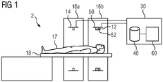
- FIG. 1 illustrates one embodiment of a nuclear imaging system 2.
- the nuclear imaging system 2 includes a scanner for at least a first modality 12 provided in a first gantry 16a.
- the first modality 12 includes a plurality of detectors 50 configured to detect an annihilation photon, gamma ray, and/or other nuclear imaging event.
- the first modality 12 is a computerized tomography (CT) modality.
- CT computerized tomography
- a patient 17 lies on a movable patient bed 18 that may be movable between a gantry.
- the nuclear imaging system 2 includes a scanner for a second imaging modality 14 provided in a second gantry 16b.
- the second imaging modality 14 can be any suitable imaging modality, such as, for example, photon emission tomography (PET) modality, single-photon emission tomography (SPECT) modality and/or any other suitable imaging modality.
- PET photon emission tomography
- SPECT single-photon emission to
- Scan data from the first modality 12 is stored at one or more computer databases 40 and processed by one or more computer processors 60 of a computer system 30.
- the graphical depiction of computer system 30 in FIG. 1 is provided by way of illustration only, and computer system 30 may include one or more separate computing devices.
- the imaging data sets can be provided by the first modality 12 and/or may be provided as a separate data set, such as, for example, from a memory coupled to the computer system 30.
- the computer system 30 can include one or more processing electronics for processing a signal received from one of the plurality of detectors 50.
- FIG. 2A illustrates a non-contrast CT scan 100a of a defect-free brain 102a.
- the defect-free brain 102a is symmetric about a midsagittal plane (MSP) (or midline) 104 and contains generally uniform distribution of brain matter.
- FIGS. 2B-2F illustrate non-contrast CT scans 100b-100f of brains 102b-102f each having at least one defect, in accordance with some embodiments.
- FIG. 2B illustrates a brain 102b containing an acute hemorrhage 106. The acute hemorrhage 106 is shown as a lighter area in the CT scan 100b.
- FIG. 2C illustrates brain 102c having a mass effect 108, for example, caused by an edema as a result of ischemic stroke.
- the mass effect 108 is shown as a darker (or denser) area in the CT scan 100c.
- FIG. 2D illustrates a brain 102d having an acute infarction 110.
- the acute infarction 110 is an arterial infarction shown as a darker (or denser) area.
- FIG. 2E illustrates brain 102e containing a mass lesion 112.
- the mass lesion 112 is shown as a lighter area.
- FIG. 2F illustrates a brain 102f containing a hydrocephalus 114.
- the illustrated hydrocephalus 114 is a ventricle hydrocephalus shown as a symmetrical darker (or denser) area. Although specific defects are illustrated and discussed herein, it will be appreciated that any suitable neural defect can be identified by the system and methods disclosed herein.
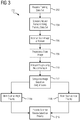
- FIG. 3 illustrates a method 200 of categorizing a scan image using a neural network, in accordance with some embodiments.
- the method 200 can be used to categorize one or more scans, such as one or more non-contrast CT scans, PET scans, SPECT scans, MRIs, etc. into a plurality of categories.
- the method 200 is configured to categorize each scan image as a high-priority scan or a low priority scan.
- Each scan image can be classified based on a probability of the scan containing one or more defects.
- the method 200 can be applied to two-dimensional (2D) image slices and/or three-dimensional (3D) image volumes.
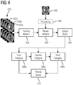
- FIG. 4 illustrates the various steps of the method 200 as applied to a 2D image slice 262.
- a system receives a training data set 250.
- the training data set 250 contains a plurality of training images 252a-252c.
- the plurality of training images 252a-252c can contain healthy, unhealthy, and/or a combination of healthy and unhealthy anatomical structure, such as healthy and/or unhealthy neurological scan images.
- Each of the training images 252a-252c can include associated data identifying information related to the training image 252a-252c, such as the presence and/or absence of a defect, the type of defect, a location of the defect, and/or any other suitable information.
- the system 30 receives a plurality of training data sets 250 each containing a plurality of training images 252a-252c with associated data.
- the system 30 can receive a first training data set containing only healthy brains, a second training data set containing only unhealthy brains having a first defect (such as an acute hemorrhage), a third training data set containing only unhealthy brains having a second defect, etc.
- the training data set(s) 250 can be received from a single source and/or can be received from multiple sources.
- the system 30 generates a neural network 260 using the training data set 250.
- the neural network 260 is generated by providing each of the training images 252a-252c in the training data set 250 to a learning network 254, such as an image-to-image learning network, a deep reinforcement learning network, a residual network, a densely connected convolution network, and/or any other suitable learning network.
- the learning network 254 reviews each of the training images 252a-252c and attempts to identify one or more parameters, such as the presence or absence of a defect, type of defect, location of a defect, etc.
- the learning network 254 can utilize any suitable learning algorithm, such as an optimization and/or statistical estimation algorithm, as just one example.
- the learning network 254 is configured to identify one or more landmarks.
- the generated neural network 260 is configured to detect one or more hemispheres, lobes, an occipital bone, orbital bones, crista galli, superior sagittal sinuses, falx cerebri, bregma (intersection of coronal and sagittal sutures) and/or any other suitable landmark.
- the generated neural network 260 can be configured to identify the locations of landmarks and/or use the landmarks to estimate other elements of the scan image, such as a mid-sagittal plane.
- the learning network 254 is a supervised learning network.
- a supervised learning networks receives the training data set 250 and attempts to identify a neural network mapping (e.g., a neural network topography) implied by the training data set 250 and that best maps a set of inputs (training images 252a-252c) to their correct output.
- a supervised learning network provided with a training data set 250 containing healthy brains and unhealthy brains generates a neural network 260 that best maps health and unhealthy brains to selected categories.
- a cost function is related to a mismatch between the selected mapping and the training data set 250.
- the cost function can include any suitable cost function, such as a mean-squared error function or categorical cross entropy loss function.
- the learning network 254 uses a backpropagation algorithm to calculate an error contribution of each neuron (e.g., node) in the neural network 260 during training.
- the cost function is configured to identify the best neural network topography based on the training data set 250.
- the system 30 receives a scan image 262, such as a non-contrast CT scan image.
- the scan image 262 is generated by a nuclear imaging system, such as the nuclear imaging system 2 illustrated in FIG. 1 .
- the scan image 262 is received from a networked system and/or storage device.
- the scan image 262 can contain one or more defects (i.e., the scan image 262 is of an unhealthy brain) or contain no defects (i.e., the scan image 262 is of a healthy brain).
- the scan image 262 is pre-processed to prepare the scan image 262 for review by the neural network 260.
- the system 30 is configured to identify one or more landmarks in the scan image 262 and estimate a midsagittal plane of the brain.
- the scan image 262 is rotated to orient the estimated midsagittal plane in a predetermined position, such as in the center of a modified scan image.
- Such preprocessing can be used to increase accuracy of the neural network 260 and decrease review time.
- step 208 is shown as a distinct pre-processing step, it will be appreciated that preprocessing of the scan image 262 can occur as part of and/or simultaneously with review of the scan image 262 by the neural network 260.
- the scan image 262 is analyzed by the neural network 260 to generate an output score 264 for the scan image 262.
- the output score 264 is indicative of one or more characterizations of the scan image 262 by the neural network 260.
- the output score 264 can include a probability that the scan image 262 contains a defect, a probability related to the presence or absence of a specific defect, the type of defect, the location of a defect, a confidence level in the determination of the presence and/or absence of a defect, and/or any other suitable value.
- the output score 264 can include a binary indication regarding one or more parameters and/or can include a value between predetermined threshold values, such as a probability between 0 and 1. It will be appreciated that the output score 264 can include any suitable output indicating the presence, absence, and/or likelihood of one or more parameters identified by the neural network 260.
- the scan image 262 is categorized based on the output score 264.
- the output score 264 is compared to a threshold value to determine whether the scan image 262 has a high probability or a low probability of containing a defect.
- the threshold value can be a predetermined value and/or a value generated by the neural network 260.
- the threshold value can be related to a confidence value of the determination of the absence or presence of a defect in the scan image 262, a minimum probability required for identifying a scan image 262 as likely containing a defect, and/or any other value related to the presence and/or absence of a defect.
- the scan image 262 is categorized based on multiple features and/or scores into one or more of a plurality of categories 266a-266c.
- a scan image 262 can be categorized into one of a plurality of categories 266a-266c corresponding to specific defects (or the absence thereof).
- the output score 264 can be used to categorize the scan image 262 into any suitable category (or categories).
- a scan image 262 is categorized as one or more categories in a first set, such as first category 266a and/or second category 266b
- the method 200 proceeds to step 214a and the scan image 262 is identified as a high-priority scan.
- the scan image 262 is identified (or marked) as being a high-priority scan.
- the method 200c proceeds to step 214b and the scan image is identified/marked as a low-priority scan.
- the scan image 262 is identified (or marked) as being a low-priority scan.
- the scan image 262 is placed in a review queue 270.
- the scan image 262 can be placed in a queue based on the categorization generated by the neural network 260 and/or a marking/identification of the scan image 262. For example, in some embodiments, if the scan image 262 is categorized as a high-priority scan at step 214a, the scan image 262 is placed earlier or at the beginning of the review queue 270. Similarly, if the scan image 262 is categorized has a low-priority scan, the scan image 262 is placed at the end of or later in the review queue 270.
- scan images 262 that are marked as high-priority are routed to a first review queue 270 for review by a first set of reviewers (such as neuro-radiologist) and scan images 262 that are marked as low-priority are routed to a second review queue 270 for review by a second set of reviewers (such as general radiologist).
- scan images 262 having a probability score below a predetermined threshold are not reviewed. The reviewer can confirm the presence of a defect in the scan image 262 and provide treatment and/or guidance to the patient or treatment team based on the review.
- the neural network 260 implements a preprocessing step, such as step 208 discussed above.
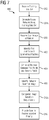
- FIG. 5 illustrates a method 300 of data preparation for preprocessing by the neural network, in accordance with some embodiments.
- FIG. 6 illustrates the various steps of the method 300 and is discussed in conjunction with FIG. 5 .
- a scan image 262 is received by a preprocessing system 350.
- the preprocessing system 350 is the same system executing a method of categorizing a scan using a neural network (such as method 200 discussed above).
- the preprocessing system 350 is separate from the categorizing system and in signal communication therewith.
- the scan image 262 can be received from any suitable source.
- the scan image can be an image obtained from a training data set 250, obtained from an imaging device 2, obtained from a memory unit, and/or obtained from any other suitable source.
- one or more landmarks are identified in the scan image 262.
- the one or more landmarks correspond to anatomical structures that are present in similar (or identical) locations in healthy brains.
- landmarks can include one or more of cristal galli, superior sagittal sinuses, falx cerebri, an occipital bone (or portion thereof), and/or any other suitable anatomical structure. Priority can be given to one or more landmarks and/or all identified landmarks can be ranked equally.
- a midsagittal plane 362 is identified.
- the midsagittal plane 362 can be identified based on the relative and/or absolute positions of one or more of the landmarks.
- one or more of the landmarks correspond to a position with respect to the midsagittal plane, such as left-of, right-of, and/or aligned with the midsagittal plane.
- Identification of a predetermined number of landmarks having known orientations and/or positions with respect to the midsagittal plane allows the preprocessing system 350 to estimate the location of the midsagittal plane 362 of the scan image 262. It will be appreciated that any suitable model(s) can be used to identify and/or position a midsagittal plane 362.
- the scan image 262 is rotated to orient the scan image along the estimated (or known) midsagittal plane 362 in a predetermined position, such as aligned with a vertical and/or horizontal center of the scan image 262, to generate a uniform image 262a.
- Orientation of the uniform image 262a ensures that each scan image 262 reviewed by the neural network 260 is similarly presented.
- orientation of the uniform image 262a can also include resampling and/or other modification of the scan image 262. Providing similarly sized and/or oriented images increases accuracy of the neural network 260 and decreases review time.
- FIG. 7 illustrates a method 400 of categorizing a scan image 262 using a plurality of symmetrical patches, in accordance with some embodiments.
- the method 400 is similar to the method 200 discussed above in conjunction with FIGS. 3-4 , and similar description is not repeated herein.
- FIGS. 8- 9 illustrate the various steps of the method 400 and are discussed in conjunction with FIG. 7 .
- a neural network 260 is generated using a training data set 250 containing a plurality of training images 252a-252c each containing a plurality of symmetrically positioned patches.
- the system 30 identifies a first patch 450a centered at a point on a first side 362a of a mid-sagittal plane 362 of a scan image 262 and a second patch 450b centered at a point on a second side 362a of the mid-sagittal plane 362.
- the first patch 450a and the second patch 450b are symmetrically located about the mid-sagittal plane 362.
- a distance between the first patch 450a and the second patch 450b is minimized.
- distance is used to denote the differences or dissimilarities between a first patch and a second patch.
- symmetrically located patches 450a, 450b are generally similar and have a small (or low) distance therebetween.
- the distance between symmetrically located patches 450a, 450b including a non-symmetrical defect e.g., acute hemorrhage, acute infarct, mass lesion, mass effect, etc.
- a distance between the first patch 450a and the second patch 450b is determined using a Siamese network 260a configured to receive pairs of symmetrically located patches 450a, 450b as inputs, as shown in FIG. 8 .
- the Siamese network 260a includes at least two branches that share weighting factors and that are driven by a hinge-based loss term and L2-norm regularization. Each of the branches classifies a received patch 450a, 450b as healthy or unhealthy.
- each branch is compared to identify non-symmetries in the patches 450a, 450b, for example, based on the difference between the classification of the patches 450a, 450b, difference in output scores 264 for each of the patches, and/or any other variation identified by the Siamese network 260a.
- the Siamese network 260a is configured to receive a plurality of multi-scale patches 450a, 450b for defect detection.
- the Siamese network 260a can include a plurality of pairs of network paths for processing a pairs of patches 450a, 450b.
- Each of the plurality of pairs of network paths include identical weighting factors for each path in the pair.
- each pair of network paths receives a pair of rescaled symmetrical patches 450a, 450b.
- Each pair of rescaled symmetrical patches 450a, 450b is centered at symmetrical points with respect to a midsagittal line 362 and can have a different applied scaling factor. The comparison and determination of the presence or absence of a defect is conducted based on a review of each of the plurality of pairs of network paths.
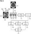
- the distance between the first patch 450a and the second patch 450b is calculated using a triplet network 260b, as shown in FIG. 9 .
- the triplet network 260b is configured to receive pairs of symmetrical patches 450a, 450b at each set of network paths.
- Each of the sets of network paths also receives a third input 456.
- the third input 456 includes a reference patch.
- the reference patch corresponds to the position of one of the first patch 450a or the second patch 450b but taken from a known-healthy image.
- the third input 456 causes the learning network 250 to generate a network based on description of patch differences as opposed to descriptions of the patches 450a, 450b, 456 themselves.
- a defect 454 (or abnormality) in the scan image 250 can be identified and highlighted based on the descriptions provided by the neural network 260a, 260b, such as the distance determination or other descriptors.
- multiple loss functions are applied by the neural network 260a, 260b. Each of the loss functions can be applied to further differentiate patches 450a, 450b to identify specific defects within low and/or non-symmetrical patches 450a, 450b.
- the pair of patches 450a, 450b is classified into a class based on the distance between the patches 450a, 450b.
- the patches 450a, 450b can be classified into a class of "healthy” or "unhealthy.”
- each of the sets of patches 450a, 450b can be classified into classes of "similar” or “dissimilar” based on the distance calculation.
- specific embodiments and classes are discussed herein, it will be appreciated that any number of classes can be used by the neural network 260.
- the classification of the patches 450a, 450b can include classification of an identified defect in the scan image.
- the classification includes a risk (or output) score for each finding generated by the neural network 260a, 260b.
- a Siamese network 260a or triplet network 260b is configured to detect a plurality of defects.
- a risk score is generated for the probability of a scan image 262 containing each of the plurality of defects.
- the risk score can include a number between, for example, 0 and 1 corresponding to the likely presence of a specific defect within the scan image.
- the risk score can be a binary output indicating distance (or likelihood of a defect) above or below a predetermined threshold.
- the classification includes a composite score generated by combining the probabilities of each category into a single composite risk score.
- neural network 260 is configured to calculate a probability for each of a plurality of defects based on the distance between the symmetrically positioned patches 450a, 450b.
- the individual probabilities can be combined into a single probability (for example, a weighted probability) that the scan image 262 contains at least one defect.
- the composite score can be used to classify a scan image 262 for review.
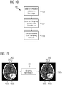
- FIG. 10 illustrates a method 500 of localization for identifying defects , in accordance with some embodiments.
- FIG. 11 illustrates the various steps of the method 500, in accordance with some embodiments.
- the neural network 260 determines the presence of a defect in a scan image 262, for example, according to one or more of the methods previously discussed.
- the neural network 260 is a Siamese 260a or triplet network 260b configured to receive symmetrical patches 450a, 450b as discussed above, although it will be appreciated that the neural network 260 can identify defects according to any of the methods discussed herein.
- the neural network 260 determines which portions (or patches) of the scan image 262 most impacted the determination of the presence of a defect, i.e., hot spots within the scan image 262. For example, in some embodiments, the neural network 260 utilizes a plurality of patches 450a, 450b to identify areas that include one or more known defects. The neural network 260 can identify the areas of highest deviation from healthy and/or symmetrical comparison patches. The patches having the highest deviation can be identified during and/or after the determination that a defect is likely present in the scan image 262.
- the system 30 generates a modified scan image 550 highlighting the hot-spots identified in step 504.
- the modified scan image 550 includes one or more highlighted areas 552a corresponding to the portions of the scan image 262 having the greatest impact on the neural network 260 determination, for example, patches having the greatest deviation from healthy and/or symmetrical comparison patches.
- the identified areas correspond to a probable location of the identified defect(s) within the scan image 262.
- the highlighted area(s) 552a allows for quick confirmation by a reviewer.
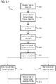
- FIG. 12 illustrates a method 600 of identifying a defect in a scan image 262 using neural network 260 configured to identify landmark deviation, in accordance with some embodiments.
- the method 600 is similar to the method 200 discussed above, and similar description is not repeated herein.
- one or more landmarks are identified in the scan image 262.
- the one or more landmarks correspond to anatomical structures that are present in similar (or identical) locations in healthy brains.
- landmarks can include one or more of a cristal galli, superior sagittal sinuses, falx cerebri, an occipital bone (or portion thereof), and/or any other suitable anatomical structure.
- the neural network 260 includes a deep image-to-image network and/or a multi-scale deep reinforcement learning network to identify reference anatomical landmarks, although it will be appreciated that any suitable neural network 260 can be used.
- the neural network 260 can include a fully convolutional implementation using full-size images and/or volumes (as compared to 2D/3D patches) for time-efficiency. Feature concatenation and deep supervision can be applied to increase accuracy of landmark identification.
- the neural network 260 is trained to follow an optimal navigation path to one or more landmarks within the scan image 262.
- the neural network 260 can be trained to identify one or more landmarks using a large number of images with annotations (i.e., indications) of the landmarks together with labels (e.g., indication of healthy or unhealthy brain) to differentiate defects and/or other factors.
- annotations i.e., indications
- labels e.g., indication of healthy or unhealthy brain
- the annotations provide a discriminative mechanism during learning and training of the neural network 260.
- the position of at least a first landmark is determined.
- the position of the first landmark can be indicative of a healthy or unhealthy brain.
- the first landmark can be displaced from an anatomically correct position in one or more directions.
- the position and/or projection of a first landmark is measured with respect to the estimated and/or determined position of the first landmark in a healthy brain (as established during neural network 260 training).
- the position and/or projection of a first landmark is determined with respect to one or more additional landmarks.
- the neural network 260 determines the likelihood of a defect being present in the scan image 262 based on the position of one or more identified landmarks.
- the neural network 260 utilizes deep generative approaches (such as variational autoencoders (VAE), generative adversarial networks (GANs), etc.), although it will be appreciated that the neural network 260 can use any suitable criteria for identifying defects based on a relative position of landmarks.
- VAE variational autoencoders
- GANs generative adversarial networks
- shape variability in the data is encoded by projecting the data on a manifold, where abnormal scans are anticipated to be positioned away from the normal appearing ones.
- the abnormal scans are expected to have a lower likelihood (e.g., a lower match) when provided to a discriminative network when the GAN is trained using normal scans.
- a lower likelihood e.g., a lower match
- the neural network 260 can utilize any suitable approach for identifying defects.
- the neural network 260 provides the scan image 262 to the review queue 270 based on the priority determination in step 606 for review by a radiologist (or other reviewer).
- expert knowledge e.g., processed diagnostic reports including semantic information with respect to anatomy
- knowing the location of landmarks with respect to others can help determine whether displacements occur for certain landmarks, indicating abnormality.
- the surrounding tissues, or bone of the landmarks can also be affected (i.e edema after hemorrhage causing the brain tissue to show darker in the scan image), therefore also introducing additional features to characterize the abnormality.
- FIG. 13 is a block diagram of a system 700 including the nuclear imaging detector 2 and a computer system 700.
- the computer system 30 can be used in some embodiments, e.g., for implementing the system 30 controlling the nuclear imaging detector 2.
- Computer system 500 may include one or more processors 502. Each processor 502 is connected to a communication infrastructure 506 (e.g., a communications bus, cross-over bar, or network).
- the processor 500 can be implemented as a central processing unit, an embedded processor or microcontroller, or an application-specific integrated circuit (ASIC).
- Computer system 500 may include a display interface 522 that forwards graphics, text, and other data from the communication infrastructure 506 (or from a frame buffer, not shown) for display on the display unit 524 to a user.
- Computer system 500 may also include a main memory 504, such as a random access memory (RAM), and a secondary memory 508.
- the main memory 504 and/or the secondary memory 508 comprise a dynamic random access memory (DRAM).
- the secondary memory 508 may include, for example, a hard disk drive (HDD) 910 and/or removable storage drive 512, which may represent a solid state memory, an optical disk drive, a flash drive, a magnetic tape drive, or the like.
- the removable storage drive 512 reads from and/or writes to a removable storage unit 516.
- Removable storage unit 516 may be an optical disk, magnetic disk, floppy disk, magnetic tape, or the like.
- the removable storage unit 516 may include a computer readable storage medium having tangibly stored therein (or embodied thereon) data and/or computer software instructions, e.g., for causing the processor(s) to perform various operations.
- secondary memory 508 may include other devices for allowing computer programs or other instructions to be loaded into computer system 500.
- Secondary memory 508 may include a removable storage unit 518 and a corresponding removable storage interface 514, which may be similar to removable storage drive 512, with its own removable storage unit 516. Examples of such removable storage units include, but are not limited to, universal serial bus (USB) or flash drives, which allow software and data to be transferred from the removable storage unit 516, 518 to computer system 500.
- USB universal serial bus
- flash drives which allow software and data to be transferred from the removable storage unit 516, 518 to computer system 500.
- Computer system 500 may also include a communications interface (e.g., networking interface) 520.
- Communications interface 520 allows instructions and data to be transferred between computer system 500 and nuclear imaging detector 2.
- Communications interface 520 also provides communications with other external devices. Examples of communications interface 520 may include a modem, Ethernet interface, wireless network interface (e.g., radio frequency, IEEE 802.11 interface, Bluetooth interface, or the like), a Personal Computer Memory Card International Association (PCMCIA) slot and card, or the like.
- Instructions and data transferred via communications interface 520 may be in the form of signals, which may be electronic, electromagnetic, optical, or the like that are capable of being received by communications interface 520. These signals may be provided to communications interface 520 via a communications path (e.g., channel), which may be implemented using wire, cable, fiber optics, a telephone line, a cellular link, a radio frequency (RF) link and other communication channels.
- RF radio frequency
- the methods and system described herein may be at least partially embodied in the form of computer-implemented processes and apparatus for practicing those processes.
- the disclosed methods may also be at least partially embodied in the form of tangible, non-transitory machine readable storage media encoded with computer program code.
- the media may include, for example, RAMs, ROMs, CD-ROMs, DVD-ROMs, BD-ROMs, hard disk drives, flash memories, or any other non-transitory machine-readable storage medium, wherein, when the computer program code is loaded into and executed by a computer, the computer becomes an apparatus for practicing the method.
- the methods may also be at least partially embodied in the form of a computer into which computer program code is loaded and/or executed, such that, the computer becomes a special purpose computer for practicing the methods.
- the computer program code segments configure the processor to create specific connections, circuits, and algorithms for implementing the methods disclosed herein.
Landscapes
- Engineering & Computer Science (AREA)
- Health & Medical Sciences (AREA)
- Medical Informatics (AREA)
- General Health & Medical Sciences (AREA)
- Public Health (AREA)
- Theoretical Computer Science (AREA)
- Physics & Mathematics (AREA)
- Biomedical Technology (AREA)
- Life Sciences & Earth Sciences (AREA)
- Computer Vision & Pattern Recognition (AREA)
- General Physics & Mathematics (AREA)
- Radiology & Medical Imaging (AREA)
- Nuclear Medicine, Radiotherapy & Molecular Imaging (AREA)
- Pathology (AREA)
- Data Mining & Analysis (AREA)
- Epidemiology (AREA)
- Primary Health Care (AREA)
- Databases & Information Systems (AREA)
- Evolutionary Computation (AREA)
- Molecular Biology (AREA)
- Artificial Intelligence (AREA)
- Multimedia (AREA)
- Quality & Reliability (AREA)
- Animal Behavior & Ethology (AREA)
- Surgery (AREA)
- Veterinary Medicine (AREA)
- Heart & Thoracic Surgery (AREA)
- Optics & Photonics (AREA)
- High Energy & Nuclear Physics (AREA)
- Biophysics (AREA)
- Biodiversity & Conservation Biology (AREA)
- Computing Systems (AREA)
- Software Systems (AREA)
- Oral & Maxillofacial Surgery (AREA)
- Dentistry (AREA)
- Neurology (AREA)
- Pulmonology (AREA)
- Image Analysis (AREA)
- Apparatus For Radiation Diagnosis (AREA)
Abstract
Description
- Aspects of the present disclosure relate in general to detection of abnormalities in a patient based on a scan image, and more particularly to identification of abnormalities and prioritization of scan image reviews based on abnormality detection.
- Nuclear imaging, such as non-contrast computerized tomography (CT) scans, are commonly used to generate cross-sectional imaging studies during emergency and/or non-emergency medicine. Images generated during a scan (i.e., scan images) serve as a screening tool to identify defects (or abnormalities) in a patient's brain, if present. Common defects identified through non-contrast CT scans include acute hemorrhage, acute infarction, hydrocephalus, mass effect, mass lesion, and intracranial hemorrhage, among others.
- In current health settings, a radiologist visually reviews each scan to identify abnormalities. Many scan images lack any visible findings but must still be reviewed, increasing patient treatment time and decreasing timeliness of critical finding identification. Existing screening workflow utilizes non-imaging information such as patient age, type and severity of incident, and manifestations of symptoms to attempt to prioritize review of scans by radiologist. Although such screening workflows can provide some filtering, existing systems can result in delayed review and identification of critical findings, lowering patient outcomes and increasing costs.
- In various embodiments, a method of reviewing neural scans includes receiving at least one landmark corresponding to an anatomical region and receiving a plurality of images of tissue including the anatomical region. A neural network is generated and configured to differentiate between healthy tissue and unhealthy tissue within the anatomical region. The neural network is generated by a machine learning process configured to receive the plurality of images of tissue and generate a plurality of weighting factors configured to differentiate between healthy tissue and unhealthy tissue. At least one patient image of tissue including the anatomical region is received and the neural network determines whether the at least one patient image of tissue includes healthy or unhealthy tissue.
Preferred is a method, wherein the neural network includes a first set and a second set of identical nodes, wherein the anatomical region comprises a symmetrical anatomical region, and wherein the at least one patient image includes a first patch corresponding to a first side of the symmetrical anatomical region and a second patch corresponding to a second side of the symmetrical anatomical region. Preferably the first patch is provided to the first set of identical nodes and the second patch is provided to the second set of identical nodes and/or the neural network comprises a third set of identical nodes, wherein the third set of identical nodes is configured to receive a reference patch.
Further, a method is preferred, wherein the network includes a plurality of skip connections configured to minimize overfitting.
Preferred is a method, comprising generating, via the neural network, impact maps configured to identify an influence of one or more voxels in the determination.
Preferred is a method, wherein the plurality of images and the at least one patient image are contrast computed tomography images.
Further, a method is preferred, the method comprising:
receiving a plurality of patient images; determining, via the neural network, a severity of unhealthy tissue in each of the plurality of patient images; and ranking, by the neural network, each of the plurality of patient images according to the determined severity of unhealthy tissue; and providing each of the plurality of patient images in rank order for further review.
Preferred is a method, wherein the neural network is configured to identify at least one of a hemorrhage, an acute infarct, hydrocephalus, a mass effect, and/or a mass lesion and/or wherein the neural network is configured to identify unhealthy tissue based on a change in a position of at least one landmark. - In various embodiments, a system for reviewing neural scans includes an imaging modality configured to obtain a neural image of a patient and a processor configured to implement a neural network. The neural network is generated by receiving at least one landmark corresponding to an anatomical region, receiving a plurality of images of tissue including the anatomical region, and performing a machine learning process configured to review the plurality of images of tissue and generate a plurality of weighting factors configured to differentiate between healthy tissue and unhealthy tissue. The processor is configured to identify, via the neural network, a defect in the neural image.
Preferred is a system, wherein the neural network includes a first set and a second set of identical nodes, wherein the neural scan includes a first patch corresponding to a first side of a symmetrical anatomical region and a second patch corresponding to a second side of the symmetrical anatomical region.
Preferred is further a system, wherein the first patch is provided to the first set of identical nodes and the second patch is provided to the second set of identical nodes and/or wherein the neural network comprises a third set of identical nodes, wherein the third set of identical nodes is configured to receive a reference patch.
Further, a system is preferred, comprising generating, via the neural network, impact maps configured to identify an influence of one or more voxels.
Preferred is a system, wherein the imaging modality is a computerized-tomography (CT) modality.
Preferred is further a system, comprising: receiving a plurality of patient images; determining, via the neural network, a severity of unhealthy tissue in each of the plurality of patient images; and ranking, by the neural network, each of the plurality of patient images according to the determined severity of unhealthy tissue.
Preferred is further a system, wherein the defect is at least one of a hemorrhage, an acute infarct, hydrocephalus, a mass effect, and/or a mass lesion. - In various embodiments, a non-transitory computer-readable medium encoded with computer executable instructions is also disclosed. The computer executable instructions, when executed by a computer in a system for reviewing neural scans cause the system for reviewing neural scans to execute the steps of: receiving at least one landmark corresponding to an anatomical region, receiving a plurality of images of tissue including the anatomical region, generating a neural network configured to differentiate between healthy tissue and unhealthy tissue within the anatomical region, receiving at least one patient image of tissue including the anatomical region , and determining, via the neural network, whether the at least one patient image of tissue includes healthy or unhealthy tissue . The neural network is generated by a machine learning process configured to receive the plurality of images of tissue and generate a plurality of weighting factors configured to differentiate between healthy tissue and unhealthy tissue.
- The following will be apparent from elements of the figures, which are provided for illustrative purposes and are not necessarily drawn to scale.
-
FIG. 1 illustrates a nuclear imaging system, in accordance with some embodiments. -
FIG. 2A illustrates a non-contrast CT scan of a healthy brain. -
FIG. 2B illustrates a non-contrast CT scan of a brain containing an acute hemorrhage. -
FIG. 2C illustrates a non-contrast CT scan of a brain containing a mass effect. -
FIG. 2D illustrates a non-contrast CT scan of a brain containing an acute infarction. -
FIG. 2E illustrates a non-contrast CT scan of a brain containing a mass lesion. -
FIG. 2F illustrates a non-contrast CT scan of a brain containing a hydrocephalus. -
FIG. 3 is a flowchart illustrating a method of categorizing a scan using a neural network, in accordance with some embodiments. -
FIG. 4 illustrates the steps of the method of categorizing a scan image illustrated inFIG. 3 , in accordance with some embodiments. -
FIG. 5 is a flowchart illustrating a method of data preparation for processing by the neural network, in accordance with some embodiments. -
FIG. 6 illustrates the steps of the method of data preparation illustrated inFIG. 5 , in accordance with some embodiments. -
FIG. 7 is a flowchart illustrating illustrates a method of categorizing a scan image based using symmetrical patches, in accordance with some embodiments. -
FIG. 8 illustrates the method of categorizing a scan image ofFIG. 7 using a Siamese network, in accordance with some embodiments. -
FIG. 9 illustrates the method of categorizing a scan image ofFIG. 7 using a triplet network, in accordance with some embodiments. -
FIG. 10 is a flowchart illustrating a method of localization for identifying and displaying regions of interest, in accordance with some embodiments. -
FIG. 11 illustrates the method of localization ofFIG. 10 , in accordance with some embodiments. -
FIG. 12 is a flowchart illustrating a method of categorizing a scan image using landmark deviation, in accordance with some embodiments. -
FIG. 13 is a block diagram of a computer system, in accordance with some embodiments. - This description of the exemplary embodiments is intended to be read in connection with the accompanying drawings, which are to be considered part of the entire written description. As used herein, the term "healthy," "normal," and "defect-free" are used interchangeably to refer to an anatomical structure (such as a brain) that does not include any abnormalities, defects, or other pathologies therein. As used herein, the term "unhealthy," "abnormal," and "defect-containing" are used interchangeably to refer to an anatomical structure (such as a brain) containing at least one abnormality, defect, or other pathology.
- In various embodiments, a system and method for categorizing a scan of patient's brain is disclosed. The system is configured to receive a scan image containing one or more anatomical structures, such as a brain. The scan image can be generated by an imaging device, such as a nuclear imaging system, loaded from a memory module, and/or otherwise provided to the system. The system includes a neural network configured to perform defect identification and detection. The neural network is configured to receive the scan image and generate an output with respect to the presence or absence of a defect in the scan image. The neural network can be generated by a learning network configured to receive a training data set containing a plurality of scan images.
-
FIG. 1 illustrates one embodiment of anuclear imaging system 2. Thenuclear imaging system 2 includes a scanner for at least afirst modality 12 provided in afirst gantry 16a. Thefirst modality 12 includes a plurality ofdetectors 50 configured to detect an annihilation photon, gamma ray, and/or other nuclear imaging event. In various embodiments, thefirst modality 12 is a computerized tomography (CT) modality. A patient 17 lies on amovable patient bed 18 that may be movable between a gantry. In some embodiments, thenuclear imaging system 2 includes a scanner for asecond imaging modality 14 provided in asecond gantry 16b. Thesecond imaging modality 14 can be any suitable imaging modality, such as, for example, photon emission tomography (PET) modality, single-photon emission tomography (SPECT) modality and/or any other suitable imaging modality. - Scan data from the
first modality 12 is stored at one ormore computer databases 40 and processed by one ormore computer processors 60 of acomputer system 30. The graphical depiction ofcomputer system 30 inFIG. 1 is provided by way of illustration only, andcomputer system 30 may include one or more separate computing devices. The imaging data sets can be provided by thefirst modality 12 and/or may be provided as a separate data set, such as, for example, from a memory coupled to thecomputer system 30. Thecomputer system 30 can include one or more processing electronics for processing a signal received from one of the plurality ofdetectors 50. -
FIG. 2A illustrates anon-contrast CT scan 100a of a defect-free brain 102a. The defect-free brain 102a is symmetric about a midsagittal plane (MSP) (or midline) 104 and contains generally uniform distribution of brain matter.FIGS. 2B-2F illustrate non-contrast CT scans 100b-100f ofbrains 102b-102f each having at least one defect, in accordance with some embodiments.FIG. 2B illustrates abrain 102b containing anacute hemorrhage 106. Theacute hemorrhage 106 is shown as a lighter area in theCT scan 100b.FIG. 2C illustratesbrain 102c having amass effect 108, for example, caused by an edema as a result of ischemic stroke. Themass effect 108 is shown as a darker (or denser) area in theCT scan 100c.FIG. 2D illustrates abrain 102d having anacute infarction 110. Theacute infarction 110 is an arterial infarction shown as a darker (or denser) area.FIG. 2E illustratesbrain 102e containing amass lesion 112. Themass lesion 112 is shown as a lighter area.FIG. 2F illustrates abrain 102f containing ahydrocephalus 114. The illustratedhydrocephalus 114 is a ventricle hydrocephalus shown as a symmetrical darker (or denser) area. Although specific defects are illustrated and discussed herein, it will be appreciated that any suitable neural defect can be identified by the system and methods disclosed herein. - As shown in
FIGS. 2B-2F , each of thebrains 102b-102fhaving a defect 106-114 can be identified through non-contrast CT imaging. Identification of defects 106-114 in a timely manner is essential for providing proper and timely care to patients.FIG. 3 illustrates amethod 200 of categorizing a scan image using a neural network, in accordance with some embodiments. Themethod 200 can be used to categorize one or more scans, such as one or more non-contrast CT scans, PET scans, SPECT scans, MRIs, etc. into a plurality of categories. For example, in some embodiments, themethod 200 is configured to categorize each scan image as a high-priority scan or a low priority scan. Each scan image can be classified based on a probability of the scan containing one or more defects. In various embodiments, themethod 200 can be applied to two-dimensional (2D) image slices and/or three-dimensional (3D) image volumes.FIG. 4 illustrates the various steps of themethod 200 as applied to a2D image slice 262. - At
step 202, a system, such ascomputer system 30 illustrated inFIG. 1 , receives atraining data set 250. Thetraining data set 250 contains a plurality oftraining images 252a-252c. The plurality oftraining images 252a-252c can contain healthy, unhealthy, and/or a combination of healthy and unhealthy anatomical structure, such as healthy and/or unhealthy neurological scan images. Each of thetraining images 252a-252c can include associated data identifying information related to thetraining image 252a-252c, such as the presence and/or absence of a defect, the type of defect, a location of the defect, and/or any other suitable information. In some embodiments, thesystem 30 receives a plurality oftraining data sets 250 each containing a plurality oftraining images 252a-252c with associated data. For example, thesystem 30 can receive a first training data set containing only healthy brains, a second training data set containing only unhealthy brains having a first defect (such as an acute hemorrhage), a third training data set containing only unhealthy brains having a second defect, etc. The training data set(s) 250 can be received from a single source and/or can be received from multiple sources. - At
step 204, thesystem 30 generates aneural network 260 using thetraining data set 250. Theneural network 260 is generated by providing each of thetraining images 252a-252c in thetraining data set 250 to alearning network 254, such as an image-to-image learning network, a deep reinforcement learning network, a residual network, a densely connected convolution network, and/or any other suitable learning network. Thelearning network 254 reviews each of thetraining images 252a-252c and attempts to identify one or more parameters, such as the presence or absence of a defect, type of defect, location of a defect, etc. Thelearning network 254 can utilize any suitable learning algorithm, such as an optimization and/or statistical estimation algorithm, as just one example. In some embodiments, thelearning network 254 is configured to identify one or more landmarks. For example, in various embodiments, the generatedneural network 260 is configured to detect one or more hemispheres, lobes, an occipital bone, orbital bones, crista galli, superior sagittal sinuses, falx cerebri, bregma (intersection of coronal and sagittal sutures) and/or any other suitable landmark. The generatedneural network 260 can be configured to identify the locations of landmarks and/or use the landmarks to estimate other elements of the scan image, such as a mid-sagittal plane. - In some embodiments, the
learning network 254 is a supervised learning network. A supervised learning networks receives thetraining data set 250 and attempts to identify a neural network mapping (e.g., a neural network topography) implied by thetraining data set 250 and that best maps a set of inputs (training images 252a-252c) to their correct output. For example, a supervised learning network provided with atraining data set 250 containing healthy brains and unhealthy brains generates aneural network 260 that best maps health and unhealthy brains to selected categories. A cost function is related to a mismatch between the selected mapping and thetraining data set 250. The cost function can include any suitable cost function, such as a mean-squared error function or categorical cross entropy loss function. In some embodiments, thelearning network 254 uses a backpropagation algorithm to calculate an error contribution of each neuron (e.g., node) in theneural network 260 during training. The cost function is configured to identify the best neural network topography based on thetraining data set 250. - At
step 206, thesystem 30 receives ascan image 262, such as a non-contrast CT scan image. In some embodiments, thescan image 262 is generated by a nuclear imaging system, such as thenuclear imaging system 2 illustrated inFIG. 1 . In other embodiments, thescan image 262 is received from a networked system and/or storage device. Thescan image 262 can contain one or more defects (i.e., thescan image 262 is of an unhealthy brain) or contain no defects (i.e., thescan image 262 is of a healthy brain). - At
optional step 208, thescan image 262 is pre-processed to prepare thescan image 262 for review by theneural network 260. For example, in some embodiments, thesystem 30 is configured to identify one or more landmarks in thescan image 262 and estimate a midsagittal plane of the brain. In some embodiments, thescan image 262 is rotated to orient the estimated midsagittal plane in a predetermined position, such as in the center of a modified scan image. Such preprocessing can be used to increase accuracy of theneural network 260 and decrease review time. Althoughstep 208 is shown as a distinct pre-processing step, it will be appreciated that preprocessing of thescan image 262 can occur as part of and/or simultaneously with review of thescan image 262 by theneural network 260. - At
step 210, thescan image 262 is analyzed by theneural network 260 to generate anoutput score 264 for thescan image 262. Theoutput score 264 is indicative of one or more characterizations of thescan image 262 by theneural network 260. Theoutput score 264 can include a probability that thescan image 262 contains a defect, a probability related to the presence or absence of a specific defect, the type of defect, the location of a defect, a confidence level in the determination of the presence and/or absence of a defect, and/or any other suitable value. Theoutput score 264 can include a binary indication regarding one or more parameters and/or can include a value between predetermined threshold values, such as a probability between 0 and 1. It will be appreciated that theoutput score 264 can include any suitable output indicating the presence, absence, and/or likelihood of one or more parameters identified by theneural network 260. - At
step 212, thescan image 262 is categorized based on theoutput score 264. For example, in some embodiments, theoutput score 264 is compared to a threshold value to determine whether thescan image 262 has a high probability or a low probability of containing a defect. The threshold value can be a predetermined value and/or a value generated by theneural network 260. The threshold value can be related to a confidence value of the determination of the absence or presence of a defect in thescan image 262, a minimum probability required for identifying ascan image 262 as likely containing a defect, and/or any other value related to the presence and/or absence of a defect. In some embodiments, thescan image 262 is categorized based on multiple features and/or scores into one or more of a plurality ofcategories 266a-266c. For example, ascan image 262 can be categorized into one of a plurality ofcategories 266a-266c corresponding to specific defects (or the absence thereof). Although embodiments are discussed herein include specific categorizations, it will be appreciated that theoutput score 264 can be used to categorize thescan image 262 into any suitable category (or categories). - In some embodiments, if a
scan image 262 is categorized as one or more categories in a first set, such asfirst category 266a and/orsecond category 266b, themethod 200 proceeds to step 214a and thescan image 262 is identified as a high-priority scan. For example, in various embodiments, if thescan image 262 is categorized as a high-priority scan, categorized as having an output score above a predetermined minimum probability threshold, categorized as likely containing a defect, and/or any other suitable categorization, thescan image 262 is identified (or marked) as being a high-priority scan. In some embodiments, if thescan image 262 is categorized in one or more categories in a second set, such asthird category 266c, the method 200c proceeds to step 214b and the scan image is identified/marked as a low-priority scan. For example, in various embodiments, if thescan image 262 is categorized as a low-priority scan, categorized as having an output score below a predetermined minimum probability threshold, categorized as not likely containing a defect, and/or any other suitable categorization, thescan image 262 is identified (or marked) as being a low-priority scan. - At
step 216, thescan image 262 is placed in areview queue 270. Thescan image 262 can be placed in a queue based on the categorization generated by theneural network 260 and/or a marking/identification of thescan image 262. For example, in some embodiments, if thescan image 262 is categorized as a high-priority scan atstep 214a, thescan image 262 is placed earlier or at the beginning of thereview queue 270. Similarly, if thescan image 262 is categorized has a low-priority scan, thescan image 262 is placed at the end of or later in thereview queue 270. In some embodiments, scanimages 262 that are marked as high-priority are routed to afirst review queue 270 for review by a first set of reviewers (such as neuro-radiologist) and scanimages 262 that are marked as low-priority are routed to asecond review queue 270 for review by a second set of reviewers (such as general radiologist). In some embodiments, scanimages 262 having a probability score below a predetermined threshold are not reviewed. The reviewer can confirm the presence of a defect in thescan image 262 and provide treatment and/or guidance to the patient or treatment team based on the review. - In some embodiments, the
neural network 260 implements a preprocessing step, such asstep 208 discussed above.FIG. 5 illustrates amethod 300 of data preparation for preprocessing by the neural network, in accordance with some embodiments.FIG. 6 illustrates the various steps of themethod 300 and is discussed in conjunction withFIG. 5 . Atstep 302, ascan image 262 is received by apreprocessing system 350. In some embodiments, thepreprocessing system 350 is the same system executing a method of categorizing a scan using a neural network (such asmethod 200 discussed above). In other embodiments, thepreprocessing system 350 is separate from the categorizing system and in signal communication therewith. Thescan image 262 can be received from any suitable source. For example, in various embodiments, the scan image can be an image obtained from atraining data set 250, obtained from animaging device 2, obtained from a memory unit, and/or obtained from any other suitable source. - At
step 304, one or more landmarks are identified in thescan image 262. The one or more landmarks correspond to anatomical structures that are present in similar (or identical) locations in healthy brains. For example, in various embodiments, landmarks can include one or more of cristal galli, superior sagittal sinuses, falx cerebri, an occipital bone (or portion thereof), and/or any other suitable anatomical structure. Priority can be given to one or more landmarks and/or all identified landmarks can be ranked equally. - At
step 306, amidsagittal plane 362 is identified. Themidsagittal plane 362 can be identified based on the relative and/or absolute positions of one or more of the landmarks. For example, in some embodiments, one or more of the landmarks correspond to a position with respect to the midsagittal plane, such as left-of, right-of, and/or aligned with the midsagittal plane. Identification of a predetermined number of landmarks having known orientations and/or positions with respect to the midsagittal plane allows thepreprocessing system 350 to estimate the location of themidsagittal plane 362 of thescan image 262. It will be appreciated that any suitable model(s) can be used to identify and/or position amidsagittal plane 362. - At
step 308, thescan image 262 is rotated to orient the scan image along the estimated (or known)midsagittal plane 362 in a predetermined position, such as aligned with a vertical and/or horizontal center of thescan image 262, to generate auniform image 262a. Orientation of theuniform image 262a ensures that eachscan image 262 reviewed by theneural network 260 is similarly presented. In some embodiments, orientation of theuniform image 262a can also include resampling and/or other modification of thescan image 262. Providing similarly sized and/or oriented images increases accuracy of theneural network 260 and decreases review time. -
FIG. 7 illustrates amethod 400 of categorizing ascan image 262 using a plurality of symmetrical patches, in accordance with some embodiments. Themethod 400 is similar to themethod 200 discussed above in conjunction withFIGS. 3-4 , and similar description is not repeated herein.FIGS. 8- 9 illustrate the various steps of themethod 400 and are discussed in conjunction withFIG. 7 . Atstep 204a, aneural network 260 is generated using atraining data set 250 containing a plurality oftraining images 252a-252c each containing a plurality of symmetrically positioned patches. - At
step 402, thesystem 30 identifies afirst patch 450a centered at a point on afirst side 362a of amid-sagittal plane 362 of ascan image 262 and asecond patch 450b centered at a point on asecond side 362a of themid-sagittal plane 362. Thefirst patch 450a and thesecond patch 450b are symmetrically located about themid-sagittal plane 362. - At
step 404, a distance between thefirst patch 450a and thesecond patch 450b is minimized. As used herein, the term "distance" is used to denote the differences or dissimilarities between a first patch and a second patch. In a healthy brain, symmetrically locatedpatches patches - In some embodiments, a distance between the
first patch 450a and thesecond patch 450b is determined using aSiamese network 260a configured to receive pairs of symmetrically locatedpatches FIG. 8 . TheSiamese network 260a includes at least two branches that share weighting factors and that are driven by a hinge-based loss term and L2-norm regularization. Each of the branches classifies a receivedpatch patches patches output scores 264 for each of the patches, and/or any other variation identified by theSiamese network 260a. - In some embodiments, the
Siamese network 260a is configured to receive a plurality ofmulti-scale patches Siamese network 260a can include a plurality of pairs of network paths for processing a pairs ofpatches symmetrical patches symmetrical patches midsagittal line 362 and can have a different applied scaling factor. The comparison and determination of the presence or absence of a defect is conducted based on a review of each of the plurality of pairs of network paths. - In some embodiments, the distance between the
first patch 450a and thesecond patch 450b is calculated using atriplet network 260b, as shown inFIG. 9 . Thetriplet network 260b is configured to receive pairs ofsymmetrical patches third input 456. In some embodiment, thethird input 456 includes a reference patch. For example, in some embodiments, the reference patch corresponds to the position of one of thefirst patch 450a or thesecond patch 450b but taken from a known-healthy image. Thethird input 456 causes thelearning network 250 to generate a network based on description of patch differences as opposed to descriptions of thepatches - At
optional step 406, a defect 454 (or abnormality) in thescan image 250 can be identified and highlighted based on the descriptions provided by theneural network neural network patches non-symmetrical patches - At
step 212a, the pair ofpatches patches patches patches neural network 260. For example, in embodiments includingoptional step 406, the classification of thepatches - In some embodiments, the classification includes a risk (or output) score for each finding generated by the
neural network Siamese network 260a ortriplet network 260b is configured to detect a plurality of defects. A risk score is generated for the probability of ascan image 262 containing each of the plurality of defects. The risk score can include a number between, for example, 0 and 1 corresponding to the likely presence of a specific defect within the scan image. In some embodiments, the risk score can be a binary output indicating distance (or likelihood of a defect) above or below a predetermined threshold. - In some embodiments, the classification includes a composite score generated by combining the probabilities of each category into a single composite risk score. For example, in some embodiments,
neural network 260 is configured to calculate a probability for each of a plurality of defects based on the distance between the symmetrically positionedpatches scan image 262 contains at least one defect. The composite score can be used to classify ascan image 262 for review. -
FIG. 10 illustrates amethod 500 of localization for identifying defects , in accordance with some embodiments.FIG. 11 illustrates the various steps of themethod 500, in accordance with some embodiments. Atstep 502, theneural network 260 determines the presence of a defect in ascan image 262, for example, according to one or more of the methods previously discussed. In some embodiments, theneural network 260 is a Siamese 260a ortriplet network 260b configured to receivesymmetrical patches neural network 260 can identify defects according to any of the methods discussed herein. - At
step 504, theneural network 260 determines which portions (or patches) of thescan image 262 most impacted the determination of the presence of a defect, i.e., hot spots within thescan image 262. For example, in some embodiments, theneural network 260 utilizes a plurality ofpatches neural network 260 can identify the areas of highest deviation from healthy and/or symmetrical comparison patches. The patches having the highest deviation can be identified during and/or after the determination that a defect is likely present in thescan image 262. - At
step 506, thesystem 30 generates a modifiedscan image 550 highlighting the hot-spots identified instep 504. The modifiedscan image 550 includes one or more highlightedareas 552a corresponding to the portions of thescan image 262 having the greatest impact on theneural network 260 determination, for example, patches having the greatest deviation from healthy and/or symmetrical comparison patches. In some embodiments, the identified areas correspond to a probable location of the identified defect(s) within thescan image 262. The highlighted area(s) 552a allows for quick confirmation by a reviewer. -
FIG. 12 illustrates a method 600 of identifying a defect in ascan image 262 usingneural network 260 configured to identify landmark deviation, in accordance with some embodiments. The method 600 is similar to themethod 200 discussed above, and similar description is not repeated herein. Atstep 602, one or more landmarks are identified in thescan image 262. The one or more landmarks correspond to anatomical structures that are present in similar (or identical) locations in healthy brains. For example, in various embodiments, landmarks can include one or more of a cristal galli, superior sagittal sinuses, falx cerebri, an occipital bone (or portion thereof), and/or any other suitable anatomical structure. In various embodiments, theneural network 260 includes a deep image-to-image network and/or a multi-scale deep reinforcement learning network to identify reference anatomical landmarks, although it will be appreciated that any suitableneural network 260 can be used. Theneural network 260 can include a fully convolutional implementation using full-size images and/or volumes (as compared to 2D/3D patches) for time-efficiency. Feature concatenation and deep supervision can be applied to increase accuracy of landmark identification. In some embodiments, theneural network 260 is trained to follow an optimal navigation path to one or more landmarks within thescan image 262. Theneural network 260 can be trained to identify one or more landmarks using a large number of images with annotations (i.e., indications) of the landmarks together with labels (e.g., indication of healthy or unhealthy brain) to differentiate defects and/or other factors. In some embodiments, the annotations provide a discriminative mechanism during learning and training of theneural network 260. - At
step 604, the position of at least a first landmark is determined. The position of the first landmark can be indicative of a healthy or unhealthy brain. When a defect is present, the first landmark can be displaced from an anatomically correct position in one or more directions. In some embodiments, the position and/or projection of a first landmark is measured with respect to the estimated and/or determined position of the first landmark in a healthy brain (as established duringneural network 260 training). In other embodiments, the position and/or projection of a first landmark is determined with respect to one or more additional landmarks. Althoughsteps neural network 260. - At
step 606, theneural network 260 determines the likelihood of a defect being present in thescan image 262 based on the position of one or more identified landmarks. For example, in some embodiments, theneural network 260 utilizes deep generative approaches (such as variational autoencoders (VAE), generative adversarial networks (GANs), etc.), although it will be appreciated that theneural network 260 can use any suitable criteria for identifying defects based on a relative position of landmarks. For example, in embodiments including a VAE, shape variability in the data is encoded by projecting the data on a manifold, where abnormal scans are anticipated to be positioned away from the normal appearing ones. As another example, in embodiments including a GAN, the abnormal scans are expected to have a lower likelihood (e.g., a lower match) when provided to a discriminative network when the GAN is trained using normal scans. Although specific embodiments are discussed herein, it will be appreciated that theneural network 260 can utilize any suitable approach for identifying defects. - At
step 216, theneural network 260 provides thescan image 262 to thereview queue 270 based on the priority determination instep 606 for review by a radiologist (or other reviewer). In some embodiments, expert knowledge (e.g., processed diagnostic reports including semantic information with respect to anatomy) regarding how landmarks are affected by the most common and critical defects can be used to identify the type of abnormality and the severity to prioritize review of thescan image 262, although it will be appreciated that any suitable prioritization measures can be used. Knowing the location of landmarks with respect to others can help determine whether displacements occur for certain landmarks, indicating abnormality. Depending on the pathology, the surrounding tissues, or bone of the landmarks can also be affected (i.e edema after hemorrhage causing the brain tissue to show darker in the scan image), therefore also introducing additional features to characterize the abnormality. -
FIG. 13 is a block diagram of asystem 700 including thenuclear imaging detector 2 and acomputer system 700. Thecomputer system 30 can be used in some embodiments, e.g., for implementing thesystem 30 controlling thenuclear imaging detector 2.Computer system 500 may include one ormore processors 502. Eachprocessor 502 is connected to a communication infrastructure 506 (e.g., a communications bus, cross-over bar, or network). Theprocessor 500 can be implemented as a central processing unit, an embedded processor or microcontroller, or an application-specific integrated circuit (ASIC).Computer system 500 may include a display interface 522 that forwards graphics, text, and other data from the communication infrastructure 506 (or from a frame buffer, not shown) for display on the display unit 524 to a user. -
Computer system 500 may also include amain memory 504, such as a random access memory (RAM), and a secondary memory 508. Themain memory 504 and/or the secondary memory 508 comprise a dynamic random access memory (DRAM). The secondary memory 508 may include, for example, a hard disk drive (HDD) 910 and/or removable storage drive 512, which may represent a solid state memory, an optical disk drive, a flash drive, a magnetic tape drive, or the like. The removable storage drive 512 reads from and/or writes to a removable storage unit 516. Removable storage unit 516 may be an optical disk, magnetic disk, floppy disk, magnetic tape, or the like. The removable storage unit 516 may include a computer readable storage medium having tangibly stored therein (or embodied thereon) data and/or computer software instructions, e.g., for causing the processor(s) to perform various operations. - In alternative embodiments, secondary memory 508 may include other devices for allowing computer programs or other instructions to be loaded into
computer system 500. Secondary memory 508 may include a removable storage unit 518 and a corresponding removable storage interface 514, which may be similar to removable storage drive 512, with its own removable storage unit 516. Examples of such removable storage units include, but are not limited to, universal serial bus (USB) or flash drives, which allow software and data to be transferred from the removable storage unit 516, 518 tocomputer system 500. -
Computer system 500 may also include a communications interface (e.g., networking interface) 520. Communications interface 520 allows instructions and data to be transferred betweencomputer system 500 andnuclear imaging detector 2. Communications interface 520 also provides communications with other external devices. Examples of communications interface 520 may include a modem, Ethernet interface, wireless network interface (e.g., radio frequency, IEEE 802.11 interface, Bluetooth interface, or the like), a Personal Computer Memory Card International Association (PCMCIA) slot and card, or the like. Instructions and data transferred via communications interface 520 may be in the form of signals, which may be electronic, electromagnetic, optical, or the like that are capable of being received by communications interface 520. These signals may be provided to communications interface 520 via a communications path (e.g., channel), which may be implemented using wire, cable, fiber optics, a telephone line, a cellular link, a radio frequency (RF) link and other communication channels. - The methods and system described herein may be at least partially embodied in the form of computer-implemented processes and apparatus for practicing those processes. The disclosed methods may also be at least partially embodied in the form of tangible, non-transitory machine readable storage media encoded with computer program code. The media may include, for example, RAMs, ROMs, CD-ROMs, DVD-ROMs, BD-ROMs, hard disk drives, flash memories, or any other non-transitory machine-readable storage medium, wherein, when the computer program code is loaded into and executed by a computer, the computer becomes an apparatus for practicing the method. The methods may also be at least partially embodied in the form of a computer into which computer program code is loaded and/or executed, such that, the computer becomes a special purpose computer for practicing the methods. When implemented on a general-purpose processor, the computer program code segments configure the processor to create specific connections, circuits, and algorithms for implementing the methods disclosed herein.
- The previous description of embodiments is provided to enable any person skilled in the art to practice the disclosure. The various modifications to these embodiments will be readily apparent to those skilled in the art, and the generic principles defined herein may be applied to other embodiments without the use of inventive faculty. The present disclosure is not intended to be limited to the embodiments shown herein, but is to be accorded the widest scope consistent with the principles and novel features disclosed herein.
Claims (16)
- A method of reviewing neural scans, comprising:receiving at least one landmark corresponding to an anatomical region;receiving a plurality of images of tissue including the anatomical region;generating a neural network configured to differentiate between healthy tissue and unhealthy tissue within the anatomical region, wherein the neural network is generated by a machine learning process configured to receive the plurality of images of tissue and generate a plurality of weighting factors configured to differentiate between healthy tissue and unhealthy tissue;receiving at least one patient image of tissue including the anatomical region; anddetermining, via the neural network, whether the at least one patient image of tissue includes healthy or unhealthy tissue.
- The method according to claim 1, wherein the neural network includes a first set and a second set of identical nodes, wherein the anatomical region comprises a symmetrical anatomical region, and wherein the at least one patient image includes a first patch corresponding to a first side of the symmetrical anatomical region and a second patch corresponding to a second side of the symmetrical anatomical region.
- The method according to claim 2, wherein the first patch is provided to the first set of identical nodes and the second patch is provided to the second set of identical nodes
and/or
wherein the neural network comprises a third set of identical nodes, wherein the third set of identical nodes is configured to receive a reference patch. - The method according to any of the preceding claims, wherein the network includes a plurality of skip connections configured to minimize overfitting.
- The method according to any of the preceding claims, comprising generating, via the neural network, impact maps configured to identify an influence of one or more voxels in the determination.
- The method according to any of the preceding claims, wherein the plurality of images and the at least one patient image are contrast computed tomography images.
- The method according to any of the preceding claims, comprising:receiving a plurality of patient images;determining, via the neural network, a severity of unhealthy tissue in each of the plurality of patient images; andranking, by the neural network, each of the plurality of patient images according to the determined severity of unhealthy tissue; andproviding each of the plurality of patient images in rank order for further review.
- The method according to any of the preceding claims, wherein the neural network is configured to identify at least one of a hemorrhage, an acute infarct, hydrocephalus, a mass effect, and/or a mass lesion
and/or
wherein the neural network is configured to identify unhealthy tissue based on a change in a position of at least one landmark. - A system for reviewing neural scans, comprising:an imaging modality configured to obtain a neural image of a patient; anda processor configured to implement a neural network, wherein the neural network is generated by:receiving at least one landmark corresponding to an anatomical region;receiving a plurality of images of tissue including the anatomical region;performing a machine learning process configured to review the plurality of images of tissue and generate a plurality of weighting factors configured to differentiate between healthy tissue and unhealthy tissue; andwherein the processor is configured to identify, via the neural network, a defect in the neural image.
- The system according to claim 9, wherein the neural network includes a first set and a second set of identical nodes, wherein the neural scan includes a first patch corresponding to a first side of a symmetrical anatomical region and a second patch corresponding to a second side of the symmetrical anatomical region.
- The system according to claim 10, wherein the first patch is provided to the first set of identical nodes and the second patch is provided to the second set of identical nodes
and/or
wherein the neural network comprises a third set of identical nodes, wherein the third set of identical nodes is configured to receive a reference patch. - The system according to any of the preceding claims 9 to 11, comprising generating, via the neural network, impact maps configured to identify an influence of one or more voxels.
- The system according to any of the preceding claims 9 to 12, wherein the imaging modality is a computerized-tomography (CT) modality.
- The system according to any of the preceding claims 9 to 13, comprising:receiving a plurality of patient images;determining, via the neural network, a severity of unhealthy tissue in each of the plurality of patient images; andranking, by the neural network, each of the plurality of patient images according to the determined severity of unhealthy tissue.
- The system according to any of the preceding claims 9 to 14, wherein the defect is at least one of a hemorrhage, an acute infarct, hydrocephalus, a mass effect, and/or a mass lesion.
- A non-transitory computer-readable medium encoded with computer executable instructions, the computer executable instructions, when executed by a computer in a system for reviewing neural scans, cause the system for reviewing neural scans to execute the steps of:receiving at least one landmark corresponding to an anatomical region;receiving a plurality of images of tissue including the anatomical region;generating a neural network configured to differentiate between healthy tissue and unhealthy tissue within the anatomical region, wherein the neural network is generated by a machine learning process configured to receive the plurality of images of tissue and generate a plurality of weighting factors configured to differentiate between healthy tissue and unhealthy tissue;receiving at least one patient image of tissue including the anatomical region; anddetermining, via the neural network, whether the at least one patient image of tissue includes healthy or unhealthy tissue.
Applications Claiming Priority (1)
| Application Number | Priority Date | Filing Date | Title |
|---|---|---|---|
| US15/831,731 US10521911B2 (en) | 2017-12-05 | 2017-12-05 | Identification of defects in imaging scans |
Publications (2)
| Publication Number | Publication Date |
|---|---|
| EP3496034A1 true EP3496034A1 (en) | 2019-06-12 |
| EP3496034B1 EP3496034B1 (en) | 2024-02-21 |
Family
ID=64661069
Family Applications (1)
| Application Number | Title | Priority Date | Filing Date |
|---|---|---|---|
| EP18210374.7A Active EP3496034B1 (en) | 2017-12-05 | 2018-12-05 | Identification of critical findings in imaging scans |
Country Status (3)
| Country | Link |
|---|---|
| US (1) | US10521911B2 (en) |
| EP (1) | EP3496034B1 (en) |
| CN (1) | CN109886913B (en) |
Families Citing this family (15)
| Publication number | Priority date | Publication date | Assignee | Title |
|---|---|---|---|---|
| US10748277B2 (en) * | 2016-09-09 | 2020-08-18 | Siemens Healthcare Gmbh | Tissue characterization based on machine learning in medical imaging |
| CN108734211B (en) * | 2018-05-17 | 2019-12-24 | 腾讯科技(深圳)有限公司 | Method and apparatus for image processing |
| US11011257B2 (en) * | 2018-11-21 | 2021-05-18 | Enlitic, Inc. | Multi-label heat map display system |
| US11710301B2 (en) | 2019-02-06 | 2023-07-25 | Samsung Electronics Co., Ltd. | Apparatus for Q-learning for continuous actions with cross-entropy guided policies and method thereof |
| DE102019209790A1 (en) * | 2019-07-03 | 2021-01-07 | Siemens Healthcare Gmbh | Method for providing an evaluation data set from a first medical three-dimensional computer tomography data set |
| US12243297B2 (en) * | 2019-07-19 | 2025-03-04 | The Regents Of The University Of California | Expert-level detection of acute intracranial hemorrhage on head CT scans |
| CN110400345B (en) * | 2019-07-24 | 2021-06-15 | 西南科技大学 | A push-grab collaborative sorting method for radioactive waste based on deep reinforcement learning |
| GB201912149D0 (en) * | 2019-08-23 | 2019-10-09 | Univ Oxford Innovation Ltd | Computerised tomography image processing |
| US11527327B2 (en) * | 2019-11-06 | 2022-12-13 | International Business Machines Corporation | Systems and methods for detecting likelihood of malignancy for a patient using a pair of medical images |
| EP3913574B1 (en) * | 2020-05-21 | 2022-12-21 | Tata Consultancy Services Limited | Anatomical landmark detection and identification from digital radiography images containing severe skeletal deformations |
| JP2023537619A (en) * | 2020-08-12 | 2023-09-04 | エンリティック,インコーポレイテッド | Automated medical scan triage system and method for its use |
| US12299078B2 (en) * | 2020-09-07 | 2025-05-13 | Siemens Healthineers Ag | System and method for detecting anomalies in images |
| CN113436187B (en) * | 2021-07-23 | 2024-10-22 | 沈阳东软智能医疗科技研究院有限公司 | Processing method, device, medium and electronic equipment of craniocerebral CT angiography image |
| US20230149088A1 (en) * | 2021-11-17 | 2023-05-18 | Brown University | Large vessel occlusion detection and treatment prediction |
| US12400309B2 (en) * | 2023-03-08 | 2025-08-26 | UnitX, Inc. | Combining defect neural network with location neural network |
Citations (1)
| Publication number | Priority date | Publication date | Assignee | Title |
|---|---|---|---|---|
| WO2017106645A1 (en) * | 2015-12-18 | 2017-06-22 | The Regents Of The University Of California | Interpretation and quantification of emergency features on head computed tomography |
Family Cites Families (9)
| Publication number | Priority date | Publication date | Assignee | Title |
|---|---|---|---|---|
| US6141437A (en) | 1995-11-22 | 2000-10-31 | Arch Development Corporation | CAD method, computer and storage medium for automated detection of lung nodules in digital chest images |
| US6240201B1 (en) | 1998-07-24 | 2001-05-29 | Arch Development Corporation | Computerized detection of lung nodules using energy-subtracted soft-tissue and standard chest images |
| US6470092B1 (en) | 2000-11-21 | 2002-10-22 | Arch Development Corporation | Process, system and computer readable medium for pulmonary nodule detection using multiple-templates matching |
| US6795521B2 (en) | 2001-08-17 | 2004-09-21 | Deus Technologies Llc | Computer-aided diagnosis system for thoracic computer tomography images |
| US8050734B2 (en) * | 2005-09-07 | 2011-11-01 | General Electric Company | Method and system for performing patient specific analysis of disease relevant changes of a disease in an anatomical structure |
| WO2010137900A2 (en) * | 2009-05-27 | 2010-12-02 | 전남대학교 산학협력단 | Selective infracted-tissue-targeting bacteria and use thereof |
| RU2013110371A (en) * | 2010-08-13 | 2014-09-20 | Смит Энд Нефью, Инк. | DETECTION OF ANATOMIC GUIDES |
| US20140056842A1 (en) * | 2012-08-21 | 2014-02-27 | Jonathan Sackner-Bernstein | Cellular therapeutic approaches to traumatic brain and spinal cord injury |
| JP6470185B2 (en) * | 2013-01-24 | 2019-02-13 | タイラートン インターナショナル ホールディングス インコーポレイテッドTylerton International Holdings Inc. | Body structure imaging |
-
2017
- 2017-12-05 US US15/831,731 patent/US10521911B2/en active Active
-
2018
- 2018-12-05 CN CN201811479702.7A patent/CN109886913B/en active Active
- 2018-12-05 EP EP18210374.7A patent/EP3496034B1/en active Active
Patent Citations (1)
| Publication number | Priority date | Publication date | Assignee | Title |
|---|---|---|---|---|
| WO2017106645A1 (en) * | 2015-12-18 | 2017-06-22 | The Regents Of The University Of California | Interpretation and quantification of emergency features on head computed tomography |
Also Published As
| Publication number | Publication date |
|---|---|
| CN109886913A (en) | 2019-06-14 |
| US10521911B2 (en) | 2019-12-31 |
| CN109886913B (en) | 2023-09-05 |
| EP3496034B1 (en) | 2024-02-21 |
| US20190172207A1 (en) | 2019-06-06 |
Similar Documents
| Publication | Publication Date | Title |
|---|---|---|
| EP3496034B1 (en) | Identification of critical findings in imaging scans | |
| KR102243830B1 (en) | System for providing integrated medical diagnostic service and method thereof | |
| US10573000B2 (en) | System and method for medical image management | |
| US11645748B2 (en) | Three-dimensional automatic location system for epileptogenic focus based on deep learning | |
| EP3612981B1 (en) | Target detection in latent space | |
| US10679344B2 (en) | Computerized device and method for processing image data | |
| Adler et al. | Novel surface features for automated detection of focal cortical dysplasias in paediatric epilepsy | |
| JP7852869B2 (en) | Brain imaging analysis method, brain imaging analysis device, and brain imaging analysis system | |
| Liu et al. | Classification of schizophrenia based on individual hierarchical brain networks constructed from structural MRI images | |
| WO2023198224A1 (en) | Method for constructing magnetic resonance image preliminary screening model for mental disorders | |
| CN112508902B (en) | White matter high signal grading method, electronic equipment and storage medium | |
| US20230263455A1 (en) | Network-based functional imaging output for evaluating multiple sclerosis | |
| KR102313658B1 (en) | Method for, device for, and system for analazing brain image | |
| Pan et al. | Multi-classification prediction of Alzheimer’s disease based on fusing multi-modal features | |
| CN113408533B (en) | Construction method of chromosome abnormality prediction model based on fetal ultrasound image characteristic omics and diagnosis equipment | |
| US12555231B2 (en) | Detecting ischemic stroke mimic using deep learning-based analysis of medical images | |
| Macdonald‐Laurs et al. | Automated detection of bottom‐of‐sulcus dysplasia on magnetic resonance imaging–positron emission tomography in patients with drug‐resistant focal epilepsy | |
| EP3948887B1 (en) | Automated system for rapid detection and indexing of critical regions in non-contrast head ct | |
| Federau et al. | Improved Multiple Sclerosis Lesion Detection using an Intelligent Automation Software | |
| Qu et al. | Multiple classifier fusion and optimization for automatic focal cortical dysplasia detection on magnetic resonance images | |
| Liu et al. | Eye-net: An interpretable machine learning ensemble for feature engineering, classification, and lesion localization of diabetic retinopathy | |
| EP4715737A1 (en) | Computer-implemented method for reviewing at least one determined organ contour in medical imaging data | |
| EP4685735A1 (en) | Enhanced interpretability of ai results in medical imaging by supervision, and associated devices, sytems, and methods | |
| EP4150504B1 (en) | Retinal image processing | |
| Castro Silva | Medical image classification based on representational learning |
Legal Events
| Date | Code | Title | Description |
|---|---|---|---|
| PUAI | Public reference made under article 153(3) epc to a published international application that has entered the european phase |
Free format text: ORIGINAL CODE: 0009012 |
|
| STAA | Information on the status of an ep patent application or granted ep patent |
Free format text: STATUS: REQUEST FOR EXAMINATION WAS MADE |
|
| 17P | Request for examination filed |
Effective date: 20181205 |
|
| AK | Designated contracting states |
Kind code of ref document: A1 Designated state(s): AL AT BE BG CH CY CZ DE DK EE ES FI FR GB GR HR HU IE IS IT LI LT LU LV MC MK MT NL NO PL PT RO RS SE SI SK SM TR |
|
| AX | Request for extension of the european patent |
Extension state: BA ME |
|
| RBV | Designated contracting states (corrected) |
Designated state(s): AL AT BE BG CH CY CZ DE DK EE ES FI FR GB GR HR HU IE IS IT LI LT LU LV MC MK MT NL NO PL PT RO RS SE SI SK SM TR |
|
| STAA | Information on the status of an ep patent application or granted ep patent |
Free format text: STATUS: EXAMINATION IS IN PROGRESS |
|
| 17Q | First examination report despatched |
Effective date: 20200804 |
|
| GRAP | Despatch of communication of intention to grant a patent |
Free format text: ORIGINAL CODE: EPIDOSNIGR1 |
|
| STAA | Information on the status of an ep patent application or granted ep patent |
Free format text: STATUS: GRANT OF PATENT IS INTENDED |
|
| RIC1 | Information provided on ipc code assigned before grant |
Ipc: G01N 23/046 20180101ALN20231018BHEP Ipc: G06V 10/82 20220101ALI20231018BHEP Ipc: G06V 10/44 20220101ALI20231018BHEP Ipc: G16H 50/70 20180101ALI20231018BHEP Ipc: G16H 50/20 20180101ALI20231018BHEP Ipc: G16H 30/40 20180101ALI20231018BHEP Ipc: A61B 6/00 20060101ALI20231018BHEP Ipc: G06T 7/00 20170101AFI20231018BHEP |
|
| RIC1 | Information provided on ipc code assigned before grant |
Ipc: G01N 23/046 20180101ALN20231023BHEP Ipc: G06V 10/82 20220101ALI20231023BHEP Ipc: G06V 10/44 20220101ALI20231023BHEP Ipc: G16H 50/70 20180101ALI20231023BHEP Ipc: G16H 50/20 20180101ALI20231023BHEP Ipc: G16H 30/40 20180101ALI20231023BHEP Ipc: A61B 6/00 20060101ALI20231023BHEP Ipc: G06T 7/00 20170101AFI20231023BHEP |
|
| INTG | Intention to grant announced |
Effective date: 20231107 |
|
| GRAS | Grant fee paid |
Free format text: ORIGINAL CODE: EPIDOSNIGR3 |
|
| GRAA | (expected) grant |
Free format text: ORIGINAL CODE: 0009210 |
|
| STAA | Information on the status of an ep patent application or granted ep patent |
Free format text: STATUS: THE PATENT HAS BEEN GRANTED |
|
| RAP1 | Party data changed (applicant data changed or rights of an application transferred) |
Owner name: SIEMENS HEALTHINEERS AG |
|
| AK | Designated contracting states |
Kind code of ref document: B1 Designated state(s): AL AT BE BG CH CY CZ DE DK EE ES FI FR GB GR HR HU IE IS IT LI LT LU LV MC MK MT NL NO PL PT RO RS SE SI SK SM TR |
|
| REG | Reference to a national code |
Ref country code: GB Ref legal event code: FG4D |
|
| REG | Reference to a national code |
Ref country code: CH Ref legal event code: EP |
|
| REG | Reference to a national code |
Ref country code: IE Ref legal event code: FG4D |
|
| REG | Reference to a national code |
Ref country code: DE Ref legal event code: R096 Ref document number: 602018065468 Country of ref document: DE |
|
| P01 | Opt-out of the competence of the unified patent court (upc) registered |
Effective date: 20240212 |
|
| REG | Reference to a national code |
Ref country code: LT Ref legal event code: MG9D |
|
| REG | Reference to a national code |
Ref country code: NL Ref legal event code: MP Effective date: 20240221 |
|
| PG25 | Lapsed in a contracting state [announced via postgrant information from national office to epo] |
Ref country code: IS Free format text: LAPSE BECAUSE OF FAILURE TO SUBMIT A TRANSLATION OF THE DESCRIPTION OR TO PAY THE FEE WITHIN THE PRESCRIBED TIME-LIMIT Effective date: 20240621 |
|
| PG25 | Lapsed in a contracting state [announced via postgrant information from national office to epo] |
Ref country code: LT Free format text: LAPSE BECAUSE OF FAILURE TO SUBMIT A TRANSLATION OF THE DESCRIPTION OR TO PAY THE FEE WITHIN THE PRESCRIBED TIME-LIMIT Effective date: 20240221 |
|
| PG25 | Lapsed in a contracting state [announced via postgrant information from national office to epo] |
Ref country code: GR Free format text: LAPSE BECAUSE OF FAILURE TO SUBMIT A TRANSLATION OF THE DESCRIPTION OR TO PAY THE FEE WITHIN THE PRESCRIBED TIME-LIMIT Effective date: 20240522 |
|
| REG | Reference to a national code |
Ref country code: AT Ref legal event code: MK05 Ref document number: 1659756 Country of ref document: AT Kind code of ref document: T Effective date: 20240221 |
|
| PG25 | Lapsed in a contracting state [announced via postgrant information from national office to epo] |
Ref country code: RS Free format text: LAPSE BECAUSE OF FAILURE TO SUBMIT A TRANSLATION OF THE DESCRIPTION OR TO PAY THE FEE WITHIN THE PRESCRIBED TIME-LIMIT Effective date: 20240521 Ref country code: HR Free format text: LAPSE BECAUSE OF FAILURE TO SUBMIT A TRANSLATION OF THE DESCRIPTION OR TO PAY THE FEE WITHIN THE PRESCRIBED TIME-LIMIT Effective date: 20240221 Ref country code: NL Free format text: LAPSE BECAUSE OF FAILURE TO SUBMIT A TRANSLATION OF THE DESCRIPTION OR TO PAY THE FEE WITHIN THE PRESCRIBED TIME-LIMIT Effective date: 20240221 |
|
| PG25 | Lapsed in a contracting state [announced via postgrant information from national office to epo] |
Ref country code: ES Free format text: LAPSE BECAUSE OF FAILURE TO SUBMIT A TRANSLATION OF THE DESCRIPTION OR TO PAY THE FEE WITHIN THE PRESCRIBED TIME-LIMIT Effective date: 20240221 |
|
| PG25 | Lapsed in a contracting state [announced via postgrant information from national office to epo] |
Ref country code: AT Free format text: LAPSE BECAUSE OF FAILURE TO SUBMIT A TRANSLATION OF THE DESCRIPTION OR TO PAY THE FEE WITHIN THE PRESCRIBED TIME-LIMIT Effective date: 20240221 |
|
| PG25 | Lapsed in a contracting state [announced via postgrant information from national office to epo] |
Ref country code: RS Free format text: LAPSE BECAUSE OF FAILURE TO SUBMIT A TRANSLATION OF THE DESCRIPTION OR TO PAY THE FEE WITHIN THE PRESCRIBED TIME-LIMIT Effective date: 20240521 Ref country code: NO Free format text: LAPSE BECAUSE OF FAILURE TO SUBMIT A TRANSLATION OF THE DESCRIPTION OR TO PAY THE FEE WITHIN THE PRESCRIBED TIME-LIMIT Effective date: 20240521 Ref country code: NL Free format text: LAPSE BECAUSE OF FAILURE TO SUBMIT A TRANSLATION OF THE DESCRIPTION OR TO PAY THE FEE WITHIN THE PRESCRIBED TIME-LIMIT Effective date: 20240221 Ref country code: LT Free format text: LAPSE BECAUSE OF FAILURE TO SUBMIT A TRANSLATION OF THE DESCRIPTION OR TO PAY THE FEE WITHIN THE PRESCRIBED TIME-LIMIT Effective date: 20240221 Ref country code: IS Free format text: LAPSE BECAUSE OF FAILURE TO SUBMIT A TRANSLATION OF THE DESCRIPTION OR TO PAY THE FEE WITHIN THE PRESCRIBED TIME-LIMIT Effective date: 20240621 Ref country code: HR Free format text: LAPSE BECAUSE OF FAILURE TO SUBMIT A TRANSLATION OF THE DESCRIPTION OR TO PAY THE FEE WITHIN THE PRESCRIBED TIME-LIMIT Effective date: 20240221 Ref country code: GR Free format text: LAPSE BECAUSE OF FAILURE TO SUBMIT A TRANSLATION OF THE DESCRIPTION OR TO PAY THE FEE WITHIN THE PRESCRIBED TIME-LIMIT Effective date: 20240522 Ref country code: FI Free format text: LAPSE BECAUSE OF FAILURE TO SUBMIT A TRANSLATION OF THE DESCRIPTION OR TO PAY THE FEE WITHIN THE PRESCRIBED TIME-LIMIT Effective date: 20240221 Ref country code: ES Free format text: LAPSE BECAUSE OF FAILURE TO SUBMIT A TRANSLATION OF THE DESCRIPTION OR TO PAY THE FEE WITHIN THE PRESCRIBED TIME-LIMIT Effective date: 20240221 Ref country code: BG Free format text: LAPSE BECAUSE OF FAILURE TO SUBMIT A TRANSLATION OF THE DESCRIPTION OR TO PAY THE FEE WITHIN THE PRESCRIBED TIME-LIMIT Effective date: 20240221 Ref country code: AT Free format text: LAPSE BECAUSE OF FAILURE TO SUBMIT A TRANSLATION OF THE DESCRIPTION OR TO PAY THE FEE WITHIN THE PRESCRIBED TIME-LIMIT Effective date: 20240221 |
|
| PG25 | Lapsed in a contracting state [announced via postgrant information from national office to epo] |
Ref country code: PT Free format text: LAPSE BECAUSE OF FAILURE TO SUBMIT A TRANSLATION OF THE DESCRIPTION OR TO PAY THE FEE WITHIN THE PRESCRIBED TIME-LIMIT Effective date: 20240621 Ref country code: PL Free format text: LAPSE BECAUSE OF FAILURE TO SUBMIT A TRANSLATION OF THE DESCRIPTION OR TO PAY THE FEE WITHIN THE PRESCRIBED TIME-LIMIT Effective date: 20240221 |
|
| PG25 | Lapsed in a contracting state [announced via postgrant information from national office to epo] |
Ref country code: SE Free format text: LAPSE BECAUSE OF FAILURE TO SUBMIT A TRANSLATION OF THE DESCRIPTION OR TO PAY THE FEE WITHIN THE PRESCRIBED TIME-LIMIT Effective date: 20240221 Ref country code: PT Free format text: LAPSE BECAUSE OF FAILURE TO SUBMIT A TRANSLATION OF THE DESCRIPTION OR TO PAY THE FEE WITHIN THE PRESCRIBED TIME-LIMIT Effective date: 20240621 Ref country code: PL Free format text: LAPSE BECAUSE OF FAILURE TO SUBMIT A TRANSLATION OF THE DESCRIPTION OR TO PAY THE FEE WITHIN THE PRESCRIBED TIME-LIMIT Effective date: 20240221 Ref country code: LV Free format text: LAPSE BECAUSE OF FAILURE TO SUBMIT A TRANSLATION OF THE DESCRIPTION OR TO PAY THE FEE WITHIN THE PRESCRIBED TIME-LIMIT Effective date: 20240221 |
|
| PG25 | Lapsed in a contracting state [announced via postgrant information from national office to epo] |
Ref country code: DK Free format text: LAPSE BECAUSE OF FAILURE TO SUBMIT A TRANSLATION OF THE DESCRIPTION OR TO PAY THE FEE WITHIN THE PRESCRIBED TIME-LIMIT Effective date: 20240221 |
|
| PG25 | Lapsed in a contracting state [announced via postgrant information from national office to epo] |
Ref country code: SM Free format text: LAPSE BECAUSE OF FAILURE TO SUBMIT A TRANSLATION OF THE DESCRIPTION OR TO PAY THE FEE WITHIN THE PRESCRIBED TIME-LIMIT Effective date: 20240221 |
|
| PG25 | Lapsed in a contracting state [announced via postgrant information from national office to epo] |
Ref country code: CZ Free format text: LAPSE BECAUSE OF FAILURE TO SUBMIT A TRANSLATION OF THE DESCRIPTION OR TO PAY THE FEE WITHIN THE PRESCRIBED TIME-LIMIT Effective date: 20240221 Ref country code: EE Free format text: LAPSE BECAUSE OF FAILURE TO SUBMIT A TRANSLATION OF THE DESCRIPTION OR TO PAY THE FEE WITHIN THE PRESCRIBED TIME-LIMIT Effective date: 20240221 |
|
| PG25 | Lapsed in a contracting state [announced via postgrant information from national office to epo] |
Ref country code: SK Free format text: LAPSE BECAUSE OF FAILURE TO SUBMIT A TRANSLATION OF THE DESCRIPTION OR TO PAY THE FEE WITHIN THE PRESCRIBED TIME-LIMIT Effective date: 20240221 |
|
| PG25 | Lapsed in a contracting state [announced via postgrant information from national office to epo] |
Ref country code: SM Free format text: LAPSE BECAUSE OF FAILURE TO SUBMIT A TRANSLATION OF THE DESCRIPTION OR TO PAY THE FEE WITHIN THE PRESCRIBED TIME-LIMIT Effective date: 20240221 Ref country code: SK Free format text: LAPSE BECAUSE OF FAILURE TO SUBMIT A TRANSLATION OF THE DESCRIPTION OR TO PAY THE FEE WITHIN THE PRESCRIBED TIME-LIMIT Effective date: 20240221 Ref country code: RO Free format text: LAPSE BECAUSE OF FAILURE TO SUBMIT A TRANSLATION OF THE DESCRIPTION OR TO PAY THE FEE WITHIN THE PRESCRIBED TIME-LIMIT Effective date: 20240221 Ref country code: EE Free format text: LAPSE BECAUSE OF FAILURE TO SUBMIT A TRANSLATION OF THE DESCRIPTION OR TO PAY THE FEE WITHIN THE PRESCRIBED TIME-LIMIT Effective date: 20240221 Ref country code: DK Free format text: LAPSE BECAUSE OF FAILURE TO SUBMIT A TRANSLATION OF THE DESCRIPTION OR TO PAY THE FEE WITHIN THE PRESCRIBED TIME-LIMIT Effective date: 20240221 Ref country code: CZ Free format text: LAPSE BECAUSE OF FAILURE TO SUBMIT A TRANSLATION OF THE DESCRIPTION OR TO PAY THE FEE WITHIN THE PRESCRIBED TIME-LIMIT Effective date: 20240221 |
|
| REG | Reference to a national code |
Ref country code: DE Ref legal event code: R097 Ref document number: 602018065468 Country of ref document: DE |
|
| PG25 | Lapsed in a contracting state [announced via postgrant information from national office to epo] |
Ref country code: IT Free format text: LAPSE BECAUSE OF FAILURE TO SUBMIT A TRANSLATION OF THE DESCRIPTION OR TO PAY THE FEE WITHIN THE PRESCRIBED TIME-LIMIT Effective date: 20240221 |
|
| PLBE | No opposition filed within time limit |
Free format text: ORIGINAL CODE: 0009261 |
|
| STAA | Information on the status of an ep patent application or granted ep patent |
Free format text: STATUS: NO OPPOSITION FILED WITHIN TIME LIMIT |
|
| PG25 | Lapsed in a contracting state [announced via postgrant information from national office to epo] |
Ref country code: IT Free format text: LAPSE BECAUSE OF FAILURE TO SUBMIT A TRANSLATION OF THE DESCRIPTION OR TO PAY THE FEE WITHIN THE PRESCRIBED TIME-LIMIT Effective date: 20240221 |
|
| 26N | No opposition filed |
Effective date: 20241122 |
|
| PG25 | Lapsed in a contracting state [announced via postgrant information from national office to epo] |
Ref country code: SI Free format text: LAPSE BECAUSE OF FAILURE TO SUBMIT A TRANSLATION OF THE DESCRIPTION OR TO PAY THE FEE WITHIN THE PRESCRIBED TIME-LIMIT Effective date: 20240221 |
|
| PG25 | Lapsed in a contracting state [announced via postgrant information from national office to epo] |
Ref country code: MC Free format text: LAPSE BECAUSE OF FAILURE TO SUBMIT A TRANSLATION OF THE DESCRIPTION OR TO PAY THE FEE WITHIN THE PRESCRIBED TIME-LIMIT Effective date: 20240221 |
|
| REG | Reference to a national code |
Ref country code: CH Ref legal event code: PL |
|
| PG25 | Lapsed in a contracting state [announced via postgrant information from national office to epo] |
Ref country code: LU Free format text: LAPSE BECAUSE OF NON-PAYMENT OF DUE FEES Effective date: 20241205 |
|
| GBPC | Gb: european patent ceased through non-payment of renewal fee |
Effective date: 20241205 |
|
| REG | Reference to a national code |
Ref country code: BE Ref legal event code: MM Effective date: 20241231 |
|
| PG25 | Lapsed in a contracting state [announced via postgrant information from national office to epo] |
Ref country code: GB Free format text: LAPSE BECAUSE OF NON-PAYMENT OF DUE FEES Effective date: 20241205 Ref country code: BE Free format text: LAPSE BECAUSE OF NON-PAYMENT OF DUE FEES Effective date: 20241231 |
|
| PG25 | Lapsed in a contracting state [announced via postgrant information from national office to epo] |
Ref country code: FR Free format text: LAPSE BECAUSE OF NON-PAYMENT OF DUE FEES Effective date: 20241231 |
|
| PG25 | Lapsed in a contracting state [announced via postgrant information from national office to epo] |
Ref country code: CH Free format text: LAPSE BECAUSE OF NON-PAYMENT OF DUE FEES Effective date: 20241231 |
|
| PG25 | Lapsed in a contracting state [announced via postgrant information from national office to epo] |
Ref country code: IE Free format text: LAPSE BECAUSE OF NON-PAYMENT OF DUE FEES Effective date: 20241205 |
|
| PG25 | Lapsed in a contracting state [announced via postgrant information from national office to epo] |
Ref country code: CY Free format text: LAPSE BECAUSE OF FAILURE TO SUBMIT A TRANSLATION OF THE DESCRIPTION OR TO PAY THE FEE WITHIN THE PRESCRIBED TIME-LIMIT; INVALID AB INITIO Effective date: 20181205 |
|
| PGFP | Annual fee paid to national office [announced via postgrant information from national office to epo] |
Ref country code: DE Payment date: 20260219 Year of fee payment: 8 |