EP3495876A1 - Method and assembly for verifying the mounting of an ophthalmic lens in a frame and pair of spectacles comprising a frame and an ophthalmic lens mounted therein - Google Patents
Method and assembly for verifying the mounting of an ophthalmic lens in a frame and pair of spectacles comprising a frame and an ophthalmic lens mounted therein Download PDFInfo
- Publication number
- EP3495876A1 EP3495876A1 EP17306715.8A EP17306715A EP3495876A1 EP 3495876 A1 EP3495876 A1 EP 3495876A1 EP 17306715 A EP17306715 A EP 17306715A EP 3495876 A1 EP3495876 A1 EP 3495876A1
- Authority
- EP
- European Patent Office
- Prior art keywords
- frame
- image
- subject
- ophthalmic lens
- mounting
- Prior art date
- Legal status (The legal status is an assumption and is not a legal conclusion. Google has not performed a legal analysis and makes no representation as to the accuracy of the status listed.)
- Withdrawn
Links
Images

Classifications
-
- G—PHYSICS
- G02—OPTICS
- G02C—SPECTACLES; SUNGLASSES OR GOGGLES INSOFAR AS THEY HAVE THE SAME FEATURES AS SPECTACLES; CONTACT LENSES
- G02C13/00—Assembling; Repairing; Cleaning
- G02C13/003—Measuring during assembly or fitting of spectacles
- G02C13/005—Measuring geometric parameters required to locate ophtalmic lenses in spectacles frames
-
- G—PHYSICS
- G06—COMPUTING; CALCULATING OR COUNTING
- G06T—IMAGE DATA PROCESSING OR GENERATION, IN GENERAL
- G06T3/00—Geometric image transformation in the plane of the image
- G06T3/40—Scaling the whole image or part thereof
-
- G—PHYSICS
- G06—COMPUTING; CALCULATING OR COUNTING
- G06T—IMAGE DATA PROCESSING OR GENERATION, IN GENERAL
- G06T7/00—Image analysis
- G06T7/0002—Inspection of images, e.g. flaw detection
- G06T7/0012—Biomedical image inspection
- G06T7/0014—Biomedical image inspection using an image reference approach
-
- G—PHYSICS
- G06—COMPUTING; CALCULATING OR COUNTING
- G06T—IMAGE DATA PROCESSING OR GENERATION, IN GENERAL
- G06T7/00—Image analysis
- G06T7/30—Determination of transform parameters for the alignment of images, i.e. image registration
- G06T7/33—Determination of transform parameters for the alignment of images, i.e. image registration using feature-based methods
- G06T7/337—Determination of transform parameters for the alignment of images, i.e. image registration using feature-based methods involving reference images or patches
-
- G—PHYSICS
- G06—COMPUTING; CALCULATING OR COUNTING
- G06T—IMAGE DATA PROCESSING OR GENERATION, IN GENERAL
- G06T7/00—Image analysis
- G06T7/70—Determining position or orientation of objects or cameras
- G06T7/73—Determining position or orientation of objects or cameras using feature-based methods
- G06T7/74—Determining position or orientation of objects or cameras using feature-based methods involving reference images or patches
-
- G—PHYSICS
- G06—COMPUTING; CALCULATING OR COUNTING
- G06T—IMAGE DATA PROCESSING OR GENERATION, IN GENERAL
- G06T2207/00—Indexing scheme for image analysis or image enhancement
- G06T2207/20—Special algorithmic details
- G06T2207/20212—Image combination
-
- G—PHYSICS
- G06—COMPUTING; CALCULATING OR COUNTING
- G06T—IMAGE DATA PROCESSING OR GENERATION, IN GENERAL
- G06T2207/00—Indexing scheme for image analysis or image enhancement
- G06T2207/30—Subject of image; Context of image processing
- G06T2207/30004—Biomedical image processing
- G06T2207/30041—Eye; Retina; Ophthalmic
-
- G—PHYSICS
- G06—COMPUTING; CALCULATING OR COUNTING
- G06T—IMAGE DATA PROCESSING OR GENERATION, IN GENERAL
- G06T2207/00—Indexing scheme for image analysis or image enhancement
- G06T2207/30—Subject of image; Context of image processing
- G06T2207/30204—Marker
Definitions
- the invention relates to the general field of optometry and to the more specific field of lens fitting in a frame.
- the present invention relates to a method for verifying the mounting of an ophthalmic lens in a frame of a pair of spectacles.
- the invention further provides a method for mounting an ophthalmic lens in a frame of a pair of spectacles and a pair of spectacles having a frame with ophthalmic lenses mounted therein.
- the invention is finally about an assembly for verifying the mounting of at least one ophthalmic lens in a frame of a pair of spectacles.
- ophthalmic lenses in particular complex lenses such as progressive lenses or lenses with non-zero cylindrical power
- the mounting of ophthalmic lenses, in particular complex lenses such as progressive lenses or lenses with non-zero cylindrical power, in a frame of a pair of spectacles is a crucial step of the dispensing process to the subject intended to wear said pair of spectacles.
- mounting parameters such as, for example centering data, orientation data (if cylindrical power), near-vision (NV) vs. far-vision (FV) points, inset VP, must be controlled in a very careful way.
- mounting parameters depend on the subject so that it is necessary to verify the mounting of the ophthalmic lens in situ, that is with the subject wearing the frame and the pair of spectacles.
- the eye-care practitioner verifies that some fitting marks present on the lenses are well positioned in front of the pupils of the subject, in a posture which is most often not very well defined.
- one object of the invention is to provide a new method which is easy to implement and cheap, and which does not require to verify the mounting on the subject.
- the above object is achieved according to the invention by providing a method for verifying the mounting of at least one ophthalmic lens in a frame of a pair of spectacles designed to be worn by a subject, said method comprising the steps of:
- said reference image of the frame worn by the subject without the at least one ophthalmic lens is captured in a prior calibration step, wherein the subject is in a reference head posture adapted to measure the fitting height of the ophthalmic lens, that is the vertical distance between a center of the pupil of the subject and a bottom edge of the frame.
- the step of comparison comprises the following sub-steps:
- a further object of the invention is to provide a method for mounting at least one ophthalmic lens in a frame of a pair of spectacles designed to be worn by a subject, said method comprising:
- the invention further proposes a pair of spectacles comprising a frame and at least one ophthalmic lens mounted in said frame by means of a mounting method according to the invention.
- the invention provides an assembly for verifying the mounting of at least one ophthalmic lens in a frame of a pair of spectacles designed to be worn by a subject, the assembly comprising:
- the processing unit is further adapted to:
- the processing unit is further adapted to:
- the processing unit comprises:
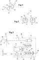
- FIG 1 a frame 30 in which an operator (for example an eye-care practitioner; not represented) wants to mount a pair 10 of two semi-finished ophthalmic lenses 11, 12 (see figure 2 ).
- an operator for example an eye-care practitioner; not represented
- the frame 30 comprises two branches 33, 34 and two circles 31, 32 (right circle 31 and left circle 32) joined together through a nasal bridge 35.
- the right circle 31, respectively the left circle 32, will receive the right lens 11, respectively the left lens 12 (after cutting and edging the lenses along the dashed lines, see figure 3 ).
- the two ophthalmic lenses 11, 12 are here complex lenses such as progressive addition lenses (PAL). They both comprise a set of markings 13, 14, 15, 16, 17, 18 in order to facilitate their mounting in the two circles 31, 32 of the frame 30.
- PAL progressive addition lenses
- This assembly 40 comprises basically:
- the image capture apparatus 41 comprises, for example, a digital camera 41 which is configured to capture a test image 50 of the frame 30 (see figure 4 ) in which the two ophthalmic lenses 11, 12 are mounted.
- the camera 41 has an optical axis 45 which is directed towards the pair of spectacles 30.
- the optical axis 45 of the camera 41 is substantially perpendicular to the average plane of the frame 30, which is here the plane YZ (see figure 3 ).
- test image 50 of the frame 30 is formed by:
- the memory unit 42 receives (arrow 46 of figure 1 ) and stores a reference image 60 of the frame 30 (see figure 5 ) in a situation where the subject 1 wears the frame 30 on his head 2 (see figure 7 ), the frame 30 being not equipped with the two ophthalmic lenses 11, 12 (bare circles 31, 32, see figure 1 ).
- the reference image 60 is formed by:
- test image 50 and the reference image 60 are then transmitted to the processing unit 43, for example a computer or a microcontroller, which compares both images 50, 60 with each other, and which outputs a "verifier", i.e. an indicator (for example a numeric or Boolean value) showing whether the two ophthalmic lenses 11, 12 are correctly (or not) mounted in the frame 30, that is whether the markings 13, 14, 15, 16, 17, 18 are well centered (or shifted) in relation to the pupils of the eyes of the subject 1.
- a "verifier" i.e. an indicator (for example a numeric or Boolean value) showing whether the two ophthalmic lenses 11, 12 are correctly (or not) mounted in the frame 30, that is whether the markings 13, 14, 15, 16, 17, 18 are well centered (or shifted) in relation to the pupils of the eyes of the subject 1.
- the processing unit 43 comprises:
- the image processing device 44 which is for example a DSP chip, receives:
- the image processing device 44 processes the test image 50 and/or the reference image 60, and outputs a processed image 70 where both images 50, 60 of the frame 30 are superimposed (see figure 6 ).
- the image processing device 44 determines, from the positions of images 73, 74 of the fitting crosses 13, 14 and from the position of the images 78, 79 of the pupils 8, 8A, a value of the distance E c between the fitting crosses 13, 14 and the centers of the pupils 8, 8A of the subject 1.
- the distance Ec is the real distance that would be measured in situ with the subject 1 wearing the pair of spectacles, wherein the frame 30 is fitted with the two ophthalmic lenses 11, 12 still displaying their fitting crosses 13, 14.
- the image processing unit 44 is programmed to:
- the calculator 48 confirms that:
- the threshold value is predetermined as a function of an inter-pupillary distance between the two pupils of the eyes of the subject, and/or a value of the optical powers of the ophthalmic lenses 11, 12.
- the threshold value in practice, one chooses the threshold value to be inferior or equal to 1 millimeter, preferably inferior to 0.5 mm.
- the reference image 60 is the image of the frame 30 captured when the subject 1 is in a predetermined reference head posture (see figure 7 and 10 ), while he (we will assume for the rest of the description that the subject is a man) is wearing, physically or virtually, the frame 30 without the lenses 11, 12.
- the reference head posture which is specific for each subject, is quite stable and does not vary very much from one day to the other. Hence, determining the reference head posture of the subject 1 is particularly useful when carrying out optical and/or eye- or head-related measurements of the subject 1, for example when trying to verify the mounting of the lenses 11, 12 in the chosen frame 30.
- the reference head posture (see figure 7 and 10 ) is determined in accordance with the position and/or the movement of one or both eyelids (upper or lower) of the subject, while he (we will assume for the rest of the description that the subject is a man) moves his head.
- the traditional "fitting height" (length B on figure 5 ) can be determined either directly or through a transfer law.
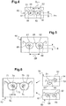
- FIG 7 We represented on figure 7 an example apparatus 100 which allows determining said reference head posture.
- This apparatus 100 comprises a digital video recorder 101 (hereinafter referred to as a camera) and a computer system 102, linked to the camera 101 by a digital cable 109 for 2-ways communication.
- a digital video recorder 101 hereinafter referred to as a camera
- a computer system 102 linked to the camera 101 by a digital cable 109 for 2-ways communication.
- the apparatus 100 preferably comprises eye-catching means 103, 104 arranged in front of the subject 1 so that he adopts an initial head posture wherein he directs his gaze 16, 17 towards a predetermined direction 18 (see figure 8 ).
- the eye-catching means 103, 104 comprise here a light source 103, for example a light-emitting diode (LED), and a semi-transparent or dichroic mirror 104 positioned and oriented in front of the subject 1 with respect to the light source 103 and the head 2 of the subject 1 so that the predetermined direction 108 is substantially horizontal, along the horizontal axis X (see arrows in figs. 7 and 8 ).
- a light source 103 for example a light-emitting diode (LED)
- a semi-transparent or dichroic mirror 104 positioned and oriented in front of the subject 1 with respect to the light source 103 and the head 2 of the subject 1 so that the predetermined direction 108 is substantially horizontal, along the horizontal axis X (see arrows in figs. 7 and 8 ).
- the LED 103 is placed just above/upright the mirror 104 which is tilted with a 45° angle relative to the vertical axis Y so that the (virtual) image of the light source 103 is positioned on the horizontal axis X (behind the mirror 104, near the camera 101), along the predetermined direction 108.
- the light source may be positioned at the same height as the eyes of the subject, so that the initial head posture is the one that the subject would adopt when looking at a far-distant point (far vision).
- the predetermined direction may be defined by the subject's gaze direction when he is looking at a fixed point straight ahead (a light source placed close to the camera) or at himself in a mirror or on a display screen, for example on the screen of his cell phone of his digital tablet.
- the camera 101 is preferably positioned in front of the head 2 of the subject 1, behind the semi-transparent or dichroic mirror 104, and has an optical axis 105 which is preferably parallel to the visual axis 108 (see figure 8 ) of the subject 1 (to avoid parallax issue when capturing the images of both eyes of the subject).
- the camera 101 is optically and mechanically set up to capture images of the head 2 and the eyes 3, 4 of the subject 1 placed in front of the camera 101.
- the computer system 102 may also comprise a video screen 102 to monitor in real time the images or films recorded by the camera 101.
- the computer system 102 comprises calculation means suitable to analyze the images captured by the camera 101 and run image-processing algorithms to extract useful information from those images and determine the looked-for reference head posture as a function of a movement or a position of at least one eyelid of the subject.
- This method comprises the steps of:
- the subject 1 sits, or stands, in front of the apparatus 100 and tries to focus on the image of the light source 103 reflected by the mirror 104.
- his gaze i.e. the lines of sight 106, 107 in figure 8
- the image defining the predetermined direction 108.
- the predetermined initial direction corresponds to the direction of the gaze of the subject when he aims at a fixed point far away and straight ahead.
- the predetermined initial direction may correspond to the direction of the gaze of the subject when he looks at himself in a mirror or on a display.
- the lighting conditions of the experiment is such that the subject 1 is in photopic conditions (high environment luminance level above roughly 300 cd/m 2 ) so that the pupil 8 of the eye 3 of the subject 1 is close to its minimum size (myosis), which is generally around 1.5 to 2 millimeters.
- the photopic conditions are obtained with ambient lighting (for example such as those usually found at an optical shop) and with the light level of the light source 13.
- the upper eyelid 9 of the right eye 3 is at this time lifted up, such that it only hides a small upper part of the iris 7, yet without vignetting the pupil 8.
- the subject 1 is asked to move his head 2 up and down (step a2; see double arrow 200 on figure 9 ) without stopping looking towards the image of the light source 103 and preferably without turning his head 2 to the left or to the right.
- the camera 101 of the apparatus 100 records, for example at a sampling rate of 30 or 60 Hz, the images of the eyes 3, 4 of the subject 1 and send the images to the computer system 102 for image processing and analysis.
- the reference head posture (see figure 10 ) is then determined as a function of the movement or the position of the upper eyelid 9 of the subject 1 during the motion of his head 2.
- the lower eyelid (reference 5 in figure 11 ) may be used in the images of the eye of the subject.
- the upper eyelid 9 is here lowered with respect to its initial position (initial head posture of figure 9 ) such that it hides almost one half of the iris 7 (see above).
- a "reference" position of the upper eyelid 9 of the eye 3 defined again by the distance, along the vertical axis 23 (parallel to axis Y), from the arch 21 to the edge 22 of the upper eyelid 9 (see figure 12 ).
- the reference head posture is determined at step b) as the posture adopted by the subject 1 at an instant where the upper eyelid 9 fits in, or respectively gets out of, the arch 21 of the corresponding eyebrow 20 of the subject 1, when the head 2 of the subject 1 is moving down, respectively is moving up.
- step b) When the reference head posture is located thanks to the movement of the upper eyelid 9, it is determined at step b) as the head posture adopted by the subject 1 at an instant where the upper eyelid 9 stops, respectively starts, moving when the head 2 of the subject 1 is moving up, respectively is moving down.
- the reference head posture may be determined either with the video camera 101 (cases of figures 10 and 12 ) or directly by a visual observation. In case of visual observation, one may equip the subject with a special device recording the inclination angle of the head of the subject. The eye-care practitioner (ECP) who carries the method then notes the inclination angle corresponding to the reference head posture of the subject.
- ECP eye-care practitioner
- the apparatus 100 and method for determining the reference head posture may be implemented when the subject is wearing, or not, eyeglasses with a frame, with or without an ophthalmic lens fitted in the frame.
- Those eyeglasses may be the one he usually wears or a new one he chose.
- the above apparatus 100 and method are particularly interesting in order to take various measurements on the subject 1 when he is in the reference head posture, as the reference head posture is kind of specific of the subject 1 in determined conditions.
- the subject 1 has already chosen a frame 30, for example in an optical store or on the Internet.
- the reference image 60 is then sent to the memory unit 42 of the assembly 40 for storage.
- a copy of the reference image 60 is also sent to the operator responsible for the mounting of the lenses 11, 12 into the frame 30.
- the operator mounts in the frame 30 the two ophthalmic lenses 11, 12 based on the markings 13, 14, 15, 16, 17, 18 and also on the reference image 60 of the frame 30 (actually on the copy of the reference image 60 he received) worn by the subject without the lenses (see above).
- the operator uses the inter-pupillary distance D EP and the fitting height B (see figure 5 ) whose values can be either measured by the optician with a ruler in the reference head posture or calculated from the reference image if one knows the scale of the reference image.
- the method for verifying the mounting may be performed, for example by the operator who mounted the lenses 11, 12 in the frame 30.
- the method for verifying the mounting comprises the steps of:
- the comparison step comprises further the following sub-steps:
- the verification of the mounting is realized based on this comparison of the determined value E c with the threshold value E c,th (see description of the processing unit 43 above).
- the sub-step of processing the test image 50 and the reference image 60 comprises (see also description of the assembly above):
- the rescaling of the test image 50 is done through a simple comparison of the images of the frames taken without the lens in the shop and with the lens in the lab.
- the target is to obtain a perfect superimposition of the two frames in those images. It may be obtained by a simple linear horizontal and/or vertical rescaling followed by a 2D best-fit process in an iterative way. It may also be achieved through an optimization process that simultaneously optimizes the size and the position of the two frames in the two images.
- the operator can finalize the mounting based on the previous verification.
Abstract
The invention relates to a method for verifying the mounting of at least one ophthalmic lens (11) in a frame (30) of a pair of spectacles designed to be worn by a subject, said method comprising the steps of:- capturing a test image (50) of the frame in which the at least one ophthalmic lens is mounted, said at least one ophthalmic lens comprising at least one marking (51) visible in said test image;- comparing said test image of the frame with a reference image (60) of the frame worn by the subject without the at least one ophthalmic lens;- verifying the mounting of said at least one ophthalmic lens in said frame based on the previous comparison.
Description
- The invention relates to the general field of optometry and to the more specific field of lens fitting in a frame.
- More precisely, the present invention relates to a method for verifying the mounting of an ophthalmic lens in a frame of a pair of spectacles.
- The invention further provides a method for mounting an ophthalmic lens in a frame of a pair of spectacles and a pair of spectacles having a frame with ophthalmic lenses mounted therein.
- The invention is finally about an assembly for verifying the mounting of at least one ophthalmic lens in a frame of a pair of spectacles.
- The mounting of ophthalmic lenses, in particular complex lenses such as progressive lenses or lenses with non-zero cylindrical power, in a frame of a pair of spectacles is a crucial step of the dispensing process to the subject intended to wear said pair of spectacles.
- In order to obtain an improvement in the visual performance and/or in the visual comfort, mounting parameters such as, for example centering data, orientation data (if cylindrical power), near-vision (NV) vs. far-vision (FV) points, inset VP, must be controlled in a very careful way. Usually such mounting parameters depend on the subject so that it is necessary to verify the mounting of the ophthalmic lens in situ, that is with the subject wearing the frame and the pair of spectacles. In practice, the eye-care practitioner verifies that some fitting marks present on the lenses are well positioned in front of the pupils of the subject, in a posture which is most often not very well defined.
- Hence, it is usually very complicated to implement a method for verifying the mounting before the dispensing of the spectacles to the subject.
- Therefore one object of the invention is to provide a new method which is easy to implement and cheap, and which does not require to verify the mounting on the subject.
- The above object is achieved according to the invention by providing a method for verifying the mounting of at least one ophthalmic lens in a frame of a pair of spectacles designed to be worn by a subject, said method comprising the steps of:
- capturing a test image of said frame in which the at least one ophthalmic lens is mounted, said at least one ophthalmic lens comprising at least one marking visible in said test image;
- comparing said test image of the frame with a reference image of the frame worn by the subject without the at least one ophthalmic lens; and
- verifying the mounting of said at least one ophthalmic lens in said frame based on the previous comparison.
- By using a reference image of the frame worn by the subject without the at least one ophthalmic lens, it is possible to test virtually, that is with an image comparison of this reference image with the test image of the frame fitted with the ophthalmic lens, the mounting of this ophthalmic lens before the dispensing of the spectacles to the subject.
- Advantageously, said reference image of the frame worn by the subject without the at least one ophthalmic lens is captured in a prior calibration step, wherein the subject is in a reference head posture adapted to measure the fitting height of the ophthalmic lens, that is the vertical distance between a center of the pupil of the subject and a bottom edge of the frame.
- In a preferred embodiment of the method according to the invention, the step of comparison comprises the following sub-steps:
- processing said test image and said reference image so as to obtain a processed image in which both images of the frame are superimposed;
- determining, from said processed image, a value of the distance between said marking and a center of a pupil of an eye of the subject to be visually corrected with said at least one ophthalmic lens;
- comparing said determined value with a threshold value, the verification of the mounting being based on said comparison.
- Other advantageous and non-limiting features of the method according to the invention comprise:
- said sub-step of processing the test image and the reference image comprises transforming said test image by rescaling the test image so that the frame in the test image has substantially the same size as the frame in the reference frame, and/or reshaping the test image so as to compensate at least one tilt angle of the frame in the test image, in at least one direction; and superimposing the transformed test image with the reference image;
- said threshold value is predetermined as a function of an inter-pupillary distance; and/or a value of the optical power of the ophthalmic lens;
- the threshold value is inferior or equal to 1 millimeter;
- said reference image is an image of the frame captured when the subject is in a predetermined reference head posture and wears, physically or virtually, said frame without the at least one ophthalmic lens, said reference head posture being advantageously used to measure the fitting height of the lens;
- said reference image is captured by image-capturing means having a capturing axis which is substantially horizontal and parallel to the gaze axis of the wearer;
- said reference head posture is determined on the basis of a criterion relative to at least one eyelid of the subject;
- the reference head posture is determined as a function of a movement or a position of said at least one eyelid of the subject when he/she moves his/her head up and down while keeping his/her gaze directed towards a predetermined initial direction;
- said predetermined initial direction corresponds to the direction of the gaze of the subject when he/she aims at a fixed point far away and straight ahead;
- said predetermined initial direction corresponds to the direction of the gaze of the subject when he/she looks at himself/herself in a mirror or on a display;
- said reference head posture is determined on the basis of a sensor;
- the method further comprises the steps of memorizing the processed image; and displaying said processed image to the subject when he/she receives and wears the frame fitted with the at least one ophthalmic lens.
- A further object of the invention is to provide a method for mounting at least one ophthalmic lens in a frame of a pair of spectacles designed to be worn by a subject, said method comprising:
- mounting in said frame said at least one ophthalmic lens comprising at least one marking based on said at least one marking and on a reference image of the frame worn by the subject without the at least one ophthalmic lens;
- verifying the mounting using a method according to the above-mentioned invention.
- finalizing the mounting based on the previous verification.
- The invention further proposes a pair of spectacles comprising a frame and at least one ophthalmic lens mounted in said frame by means of a mounting method according to the invention.
- Finally, the invention provides an assembly for verifying the mounting of at least one ophthalmic lens in a frame of a pair of spectacles designed to be worn by a subject, the assembly comprising:
- an image capture apparatus configured to capture a test image of the frame in which the at least one ophthalmic lens is mounted, said at least one ophthalmic lens comprising at least one marking visible in said test image;
- a memory unit adapted to receive and store a reference image of the frame worn by the subject without the at least one ophthalmic lens; and
- a processing unit adapted to compare said test image with said reference image and verify the mounting of said at least one ophthalmic lens in the frame based on the previous comparison.
- Advantageously, the processing unit is further adapted to:
- process said test image and said reference image so as to obtain a processed image in which both images of the frame are superimposed;
- determine, from said processed image, a value of the distance between said marking and a center of a pupil of an eye of the subject to be visually corrected with said at least one ophthalmic lens; and
- compare said determined value with a threshold value,
- In a preferred embodiment of the assembly, the processing unit is further adapted to:
- transform said test image by rescaling the test image so that the frame in the test image has substantially the same size as the frame in the reference frame; and/or reshape the test image so as to compensate at least one tilt angle of the frame in the test image, in at least one direction; and
- superimposing the transformed test image with the reference image.
- Preferably, the processing unit comprises:
- an image processing device adapted to process said test image and said reference image so as to obtain the processed image in which both images of the frame are superimposed; and determine, from said processed image, said value of the distance between said marking and the center of the pupil of the eye of the subject; and
- a calculator designed to calculate a difference value between said determined value and a predetermined threshold value; and validate the mounting based on said difference value.
- The following description, enriched with joint drawings that should be taken as non limitative examples, will help understand the invention and figure out how it can be realized.
- On joint drawings:
-
Figure 1 is a view of a frame of a pair of spectacles for the visual correction of a subject; -
Figure 2 is a front view of two ophthalmic lenses before mounting in the frame offigure 1 ; -
Figure 3 is a schematic drawing of an assembly for verifying the mounting of the two ophthalmic lenses offigure 2 in the frame offigure 1 ; -
Figure 4 represents a test image of the frame (with lenses) captured by the assembly offigure 3 ; -
Figure 5 represents a reference image of the frame (without lenses) worn on the head of the subject; -
Figure 6 represents a processed image obtained by superimposition of the test image offigure 4 with the reference image offigure 5 ; -
Figure 7 is a schematic representation of a subject in front of an apparatus according to a first embodiment of the invention; -
Figure 8 is a top view offigure 7 showing both eyes of the subject; -
Figure 9 is a schematic drawing of the eye of a subject showing his eyelids and the pupil of his eye in an initial head posture; and -
Figure 10 is a schematic drawing of the eye offigure 10 in the reference head posture; and -
Figures 11 and 12 are schematic drawings of the head of the subject in the initial head posture and in the reference head posture respectively. - We represent on
figure 1 aframe 30 in which an operator (for example an eye-care practitioner; not represented) wants to mount apair 10 of two semi-finishedophthalmic lenses 11, 12 (seefigure 2 ). - The
frame 30 comprises twobranches circles 31, 32 (right circle 31 and left circle 32) joined together through anasal bridge 35. Theright circle 31, respectively theleft circle 32, will receive theright lens 11, respectively the left lens 12 (after cutting and edging the lenses along the dashed lines, seefigure 3 ). - When the
ophthalmic lenses circles frame 30, we obtain a pair of spectacles intended to be worn by asubject 1 for his/her visual correction (myopia, presbyopia, hyperopia, etc...). - The two
ophthalmic lenses markings circles frame 30. For the following, we will consider only the twofitting crosses lenses ophthalmic lenses respective circles - We represent on
figure 3 anassembly 40 according to the invention configured to verify the mounting of the twoophthalmic lenses frame 30. - This
assembly 40 comprises basically: - an
image capture apparatus 41 to acquire afirst picture 50 of the frame 30 (seefigure 4 ); - a
memory unit 42 to store and provide (see arrow 47) asecond picture 60 of the frame 30 (seefigure 5 ) put on thehead 2 of the subject 1 (seefigure 7 ); - a
processing unit 43 to compare thefirst picture 50 with thesecond picture 60 and validate (or not) the mounting of theophthalmic lenses frame 30 based on this comparison. - The
image capture apparatus 41 comprises, for example, adigital camera 41 which is configured to capture atest image 50 of the frame 30 (seefigure 4 ) in which the twoophthalmic lenses camera 41 has anoptical axis 45 which is directed towards the pair ofspectacles 30. Preferably, theoptical axis 45 of thecamera 41 is substantially perpendicular to the average plane of theframe 30, which is here the plane YZ (seefigure 3 ). - As shown on
figure 4 , thetest image 50 of theframe 30 is formed by: - the
images circles frame 30 and of thenasal bridge 35, respectively; and - the
images ophthalmic lenses fitting crosses test image 50 of theframe 30. - Usually, for the mounting of the
ophthalmic lenses circles frame 30, the operator makes use of the fitting crosses 13, 14 to adapt: - the fitting height FH: distance between the center of the fitting cross and the bottom edge of the circle; and
- the half-pupillary distance DEP: distance between the center of the fitting cross and the middle of the nasal bridge of the frame.
- The
memory unit 42 receives (arrow 46 offigure 1 ) and stores areference image 60 of the frame 30 (seefigure 5 ) in a situation where the subject 1 wears theframe 30 on his head 2 (seefigure 7 ), theframe 30 being not equipped with the twoophthalmic lenses 11, 12 (bare circles figure 1 ). As can be seen onfigure 5 , thereference image 60 is formed by: - the
images circles frame 30 and of thenasal bridge 35, respectively; and - the
images pupils 8, 8A of the subject 1 (seefigure 7 ). - We will describe father in the following text how the
reference image 60 of theframe 30 can be captured in presence of thesubject 1. - The
test image 50 and thereference image 60 are then transmitted to theprocessing unit 43, for example a computer or a microcontroller, which compares bothimages ophthalmic lenses frame 30, that is whether themarkings subject 1. - In the preferred embodiment represented on
figure 3 , theprocessing unit 43 comprises: - an
image processing device 44 configures to process thetest image 50 and/or thereference image 60 of theframe 30; and - a
calculator 48 designed to analyze these processed images, make calculations based on them, and output said indicator. - The
image processing device 44, which is for example a DSP chip, receives: - at a first input port: the
test image 50 of the frame 30 (seefigure 4 ) acquired and transmitted by theimage capture apparatus 41 to the processing unit 43 (see above); and - at a second input port: the
reference image 60 of the frame 30 (seefigure 5 ) stored in and transmitted by thememory unit 42 to theprocessing unit 43. - Advantageously, the
image processing device 44 processes thetest image 50 and/or thereference image 60, and outputs a processedimage 70 where bothimages frame 30 are superimposed (seefigure 6 ). - From the processed
image 70, theimage processing device 44 determines, from the positions ofimages images pupils 8, 8A, a value of the distance Ec between thefitting crosses pupils 8, 8A of thesubject 1. - The distance Ec is the real distance that would be measured in situ with the subject 1 wearing the pair of spectacles, wherein the
frame 30 is fitted with the twoophthalmic lenses fitting crosses - In the preferred embodiment of
figure 3 , theimage processing unit 44 is programmed to: - transform (see
figure 6 ) thetest image 50, preferably by:- rescaling the
test image 50 so that the image of theframe 30 in thetest image 50 has substantially the same size as the image of theframe 30 in thereference image 60; and/or - reshaping the
test image 50 so as to compensate at least one tilt angle of theframe 30 in thetest image 50, in at least one direction; and
- rescaling the
- superimpose the so transformed
test image 50 with thereference image 60 to build the processedimage 70. - The
calculator 48, which is for example a CPU (stands for "Central Processing Unit"), then treats the processedimage 70 and calculates a difference value ΔE between the determined value Ec of the distance (between thefitting crosses pupils 8, 8A of the subject 1) and a predetermined threshold value Ec,th: ΔE = Ec - Ec,th. - Based on that difference value ΔE, the
calculator 48 confirms that: - if the difference value ΔE is greater than zero: the mounting of the
lenses frame 30 is correct (i.e. verification OK); and - if the difference value ΔE is lower than zero: the mounting of the
lenses frame 30 is incorrect (i.e. verification not OK). - Preferably, the threshold value is predetermined as a function of an inter-pupillary distance between the two pupils of the eyes of the subject, and/or a value of the optical powers of the
ophthalmic lenses - In practice, one chooses the threshold value to be inferior or equal to 1 millimeter, preferably inferior to 0.5 mm.
- We will describe hereafter how (i.e. in which conditions) the
reference image 60 of theframe 30 can be determined. - In the preferred embodiment represented on
figures 7-13 , thereference image 60 is the image of theframe 30 captured when thesubject 1 is in a predetermined reference head posture (seefigure 7 and 10 ), while he (we will assume for the rest of the description that the subject is a man) is wearing, physically or virtually, theframe 30 without thelenses - The reference head posture, which is specific for each subject, is quite stable and does not vary very much from one day to the other. Hence, determining the reference head posture of the subject 1 is particularly useful when carrying out optical and/or eye- or head-related measurements of the subject 1, for example when trying to verify the mounting of the
lenses frame 30. - The reference head posture (see
figure 7 and 10 ) is determined in accordance with the position and/or the movement of one or both eyelids (upper or lower) of the subject, while he (we will assume for the rest of the description that the subject is a man) moves his head. - In practice, in the reference head posture, the traditional "fitting height" (length B on
figure 5 ) can be determined either directly or through a transfer law. - We represented on
figure 7 anexample apparatus 100 which allows determining said reference head posture. - This
apparatus 100 comprises a digital video recorder 101 (hereinafter referred to as a camera) and acomputer system 102, linked to thecamera 101 by adigital cable 109 for 2-ways communication. - The
apparatus 100 preferably comprises eye-catchingmeans gaze figure 8 ). - The eye-catching
means light source 103, for example a light-emitting diode (LED), and a semi-transparent ordichroic mirror 104 positioned and oriented in front of the subject 1 with respect to thelight source 103 and thehead 2 of the subject 1 so that thepredetermined direction 108 is substantially horizontal, along the horizontal axis X (see arrows infigs. 7 and 8 ). - In other words, the
LED 103 is placed just above/upright themirror 104 which is tilted with a 45° angle relative to the vertical axis Y so that the (virtual) image of thelight source 103 is positioned on the horizontal axis X (behind themirror 104, near the camera 101), along thepredetermined direction 108. - In a variant, the light source may be positioned at the same height as the eyes of the subject, so that the initial head posture is the one that the subject would adopt when looking at a far-distant point (far vision).
- In another variants, the predetermined direction may be defined by the subject's gaze direction when he is looking at a fixed point straight ahead (a light source placed close to the camera) or at himself in a mirror or on a display screen, for example on the screen of his cell phone of his digital tablet.
- The
camera 101 is preferably positioned in front of thehead 2 of the subject 1, behind the semi-transparent ordichroic mirror 104, and has anoptical axis 105 which is preferably parallel to the visual axis 108 (seefigure 8 ) of the subject 1 (to avoid parallax issue when capturing the images of both eyes of the subject). - The
camera 101 is optically and mechanically set up to capture images of thehead 2 and theeyes camera 101. - The
computer system 102 may also comprise avideo screen 102 to monitor in real time the images or films recorded by thecamera 101. Thecomputer system 102 comprises calculation means suitable to analyze the images captured by thecamera 101 and run image-processing algorithms to extract useful information from those images and determine the looked-for reference head posture as a function of a movement or a position of at least one eyelid of the subject. - Using the
apparatus 100 offigure 7 , it is possible to perform a method for determining the reference head posture of thesubject 1. This method comprises the steps of: - a) asking the subject 1 to:
- a1) adopt an initial head posture wherein he directs his gaze towards the
predetermined direction 108; - a2) move his head up and down (see double arrow 200 on
figure 7 ) starting from the initial head posture while keeping his gaze directed towards thepredetermined direction 108; and
- a1) adopt an initial head posture wherein he directs his gaze towards the
- b) determining the reference head posture as a function of a movement or a position of at least one eyelid of the subject 1 during the motion of his head at step a2).
- We have represented on
figures 9 and 10 , thehead 2 of the subject 1 when he is respectively in the initial head posture (case offigure 9 ) and in the reference head posture (case offigure 10 ). - At the beginning of the method for determining the reference head posture, the
subject 1 sits, or stands, in front of theapparatus 100 and tries to focus on the image of thelight source 103 reflected by themirror 104. In this situation, his gaze (i.e. the lines ofsight figure 8 ) is directed towards the image, defining thepredetermined direction 108. - The predetermined initial direction corresponds to the direction of the gaze of the subject when he aims at a fixed point far away and straight ahead.
- Alternatively, the predetermined initial direction may correspond to the direction of the gaze of the subject when he looks at himself in a mirror or on a display.
- In the initial head posture (
figure 9 ), we represented onfigure 11 a detailed view of the (right)eye 3 of the subject 1 with: - the
lower eyelid 5 and theupper eyelid 9; - the
sclera 6; - the
iris 7 and thepupil 8. - Preferably, the lighting conditions of the experiment is such that the
subject 1 is in photopic conditions (high environment luminance level above roughly 300 cd/m2) so that thepupil 8 of theeye 3 of the subject 1 is close to its minimum size (myosis), which is generally around 1.5 to 2 millimeters. - In practice here, the photopic conditions are obtained with ambient lighting (for example such as those usually found at an optical shop) and with the light level of the
light source 13. - As shown on
figure 11 , theupper eyelid 9 of theright eye 3 is at this time lifted up, such that it only hides a small upper part of theiris 7, yet without vignetting thepupil 8. - In the initial head posture (
figures 9 and 11 ), one may acquire an image of theentire eye 3 of the subject 1, comprising theeyebrow 20 of the subject and the arch 21 of theeyebrow 20. Preferably, one can process the acquired image to identify the arch 21 and anedge 22 of theupper eyelid 9, and calculate an initial position of theupper eyelid 9 of theeye 3, defined by the distance, along the vertical axis 23 (parallel to axis X), from the arch 21 to theedge 22 of theupper eyelid 9. - Then, starting from the initial head posture (
figure 9 ) where thesubject 1 directs hisgaze 16 in thepredetermined direction 108, thesubject 1 is asked to move hishead 2 up and down (step a2; see double arrow 200 onfigure 9 ) without stopping looking towards the image of thelight source 103 and preferably without turning hishead 2 to the left or to the right. - During the whole motion of his
head 2, thecamera 101 of theapparatus 100 records, for example at a sampling rate of 30 or 60 Hz, the images of theeyes computer system 102 for image processing and analysis. - The reference head posture (see
figure 10 ) is then determined as a function of the movement or the position of theupper eyelid 9 of the subject 1 during the motion of hishead 2. - Alternatively, the lower eyelid (
reference 5 infigure 11 ) may be used in the images of the eye of the subject. - As shown in
figure 12 , in the reference head posture, theupper eyelid 9 is here lowered with respect to its initial position (initial head posture offigure 9 ) such that it hides almost one half of the iris 7 (see above). - In the reference head posture (
figure 10 ), one may also calculate a "reference" position of theupper eyelid 9 of theeye 3, defined again by the distance, along the vertical axis 23 (parallel to axis Y), from the arch 21 to theedge 22 of the upper eyelid 9 (seefigure 12 ). - Preferably, the reference head posture is determined at step b) as the posture adopted by the subject 1 at an instant where the
upper eyelid 9 fits in, or respectively gets out of, thearch 21 of thecorresponding eyebrow 20 of the subject 1, when thehead 2 of the subject 1 is moving down, respectively is moving up. - When the reference head posture is located thanks to the movement of the
upper eyelid 9, it is determined at step b) as the head posture adopted by the subject 1 at an instant where theupper eyelid 9 stops, respectively starts, moving when thehead 2 of the subject 1 is moving up, respectively is moving down. - The reference head posture may be determined either with the video camera 101 (cases of
figures 10 and 12 ) or directly by a visual observation. In case of visual observation, one may equip the subject with a special device recording the inclination angle of the head of the subject. The eye-care practitioner (ECP) who carries the method then notes the inclination angle corresponding to the reference head posture of the subject. - Then, in order to reproduce the reference head posture, determined previously with the method, it is possible to fit the
head 2 of the subject 1 (if he doesn't wear a frame) or the frame he wears with the above inclination device; and ask the subject 1 to tilt hishead 2 until the inclination angle equalize the value determined during the previous measurement. - The
apparatus 100 and method for determining the reference head posture may be implemented when the subject is wearing, or not, eyeglasses with a frame, with or without an ophthalmic lens fitted in the frame. Those eyeglasses may be the one he usually wears or a new one he chose. - The
above apparatus 100 and method are particularly interesting in order to take various measurements on the subject 1 when he is in the reference head posture, as the reference head posture is kind of specific of the subject 1 in determined conditions. - We will now detail the method for verifying the mounting of the
ophthalmic lenses frame 30 of a pair of spectacles according to the invention. - In practice, before verifying the mounting, the
subject 1 has already chosen aframe 30, for example in an optical store or on the Internet. - After some adjustments of the
frame 30 on thehead 2 of the subject 1, one determines the reference head posture (seefigure 7 and 10 ) and acquires the corresponding reference image 60 (seefigure 5 ) of theframe 30 worn by thesubject 1 without thelenses - Besides, one can also take the measurement of the inter-pupillary distance and of the distinctive height B of the
pupils 8, 8A in relation to the bottom edge of therespective circles figure 5 ). - The
reference image 60 is then sent to thememory unit 42 of theassembly 40 for storage. - Advantageously, a copy of the
reference image 60 is also sent to the operator responsible for the mounting of thelenses frame 30. - Then, the operator mounts in the
frame 30 the twoophthalmic lenses markings reference image 60 of the frame 30 (actually on the copy of thereference image 60 he received) worn by the subject without the lenses (see above). - In particular, the operator uses the inter-pupillary distance DEP and the fitting height B (see
figure 5 ) whose values can be either measured by the optician with a ruler in the reference head posture or calculated from the reference image if one knows the scale of the reference image. - At this stage, the method for verifying the mounting may be performed, for example by the operator who mounted the
lenses frame 30. - According to the invention, the method for verifying the mounting comprises the steps of:
- capturing the
test image 50 of theframe 30 in which the twolenses figure 4 ), both theophthalmic lenses markings test image 50; - comparing the
test image 50 of theframe 30 with thereference image 60 of theframe 30 without theophthalmic lenses figure 7 ); and - verifying the mounting of the two ophthalmic lenses in the
frame 30 based on this comparison. - Preferably, the comparison step comprises further the following sub-steps:
- processing, by means of the
image processing device 44 of theprocessing unit 43 of theassembly 10, thetest image 50 and thereference image 60 so as to obtain the processedimage 70 in which bothimages frame 30 are superimposed; - determining, from the processed
image 70, the value Ec of the distance between thefitting crosses center pupils 8, 8A of theeye figure 8 for left eye 4); and - comparing the determined value Ec with the threshold value Ec,th.
- Finally, at the end of the method according to the invention, the verification of the mounting is realized based on this comparison of the determined value Ec with the threshold value Ec,th (see description of the
processing unit 43 above). - In a preferred embodiment of the method, the sub-step of processing the
test image 50 and thereference image 60 comprises (see also description of the assembly above): - transforming the
test image 50 by rescaling thetest image 50 so that the image of theframe 30 in thetest image 50 has substantially the same size as the image of theframe 30 in thereference image 60; and/or reshaping thetest image 50 so as to compensate at least one tilt angle of theframe 30 in thetest image 50, in at least one direction (for example direction Y); and - superimposing the transformed test image with the
reference image 60. - The rescaling of the
test image 50 is done through a simple comparison of the images of the frames taken without the lens in the shop and with the lens in the lab. The target is to obtain a perfect superimposition of the two frames in those images. It may be obtained by a simple linear horizontal and/or vertical rescaling followed by a 2D best-fit process in an iterative way. It may also be achieved through an optimization process that simultaneously optimizes the size and the position of the two frames in the two images. - At the end, the operator can finalize the mounting based on the previous verification.
Claims (15)
- Method for verifying the mounting of at least one ophthalmic lens (11, 12) in a frame (30) of a pair of spectacles designed to be worn by a subject (1), said method comprising the steps of:- capturing a test image (50) of the frame (30) in which the at least one ophthalmic lens (11, 12) is mounted, said at least one ophthalmic lens (11, 12) comprising at least one marking (13, 14) visible in said test image (50);- comparing said test image (50) of the frame (30) with a reference image (60) of the frame (30) worn by the subject (1) without the at least one ophthalmic lens (11, 12); and- verifying the mounting of said at least one ophthalmic lens (11, 12) in said frame (30) based on the previous comparison.
- Method according to claim 1, wherein the step of comparison comprises the following sub-steps:- processing said test image (50) and said reference image (60) so as to obtain a processed image (70) in which both images (50, 60) of the frame (30) are superimposed;- determining, from said processed image (70), a value (Ec) of the distance between said marking (13, 14) and a center of a pupil (8, 8A) of an eye (3, 4) of the subject (1) to be visually corrected with said at least one ophthalmic lens (11, 12);- comparing said determined value (Ec) with a threshold value (Ec,th);the verification of the mounting being based on said comparison.
- Method according to claim 2, wherein said sub-step of processing the test image (50) and the reference image (60) comprises:- transforming said test image (50) by:- rescaling the test image (50) so that the frame (30) in the test image (50) has substantially the same size as the frame (30) in the reference image (60); and/or- reshaping the test image (50) so as to compensate at least one tilt angle of the frame (30) in the test image (50), in at least one direction; and- superimposing the transformed test image (50) with the reference image (60).
- Method according to claim 2 or 3, wherein the threshold value (Ec,th) is predetermined as a function of:- an inter-pupillary distance (DEP); and- a value of the optical power of the ophthalmic lens.
- Method according to anyone of claims 1 to 4, wherein the reference image (60) is an image of the frame (30) captured when the subject (1) is in a predetermined reference head posture and wears, physically or virtually, said frame (30) without the at least one ophthalmic lens (11, 12).
- Method according to claim 5, wherein said reference image (60) is captured by image-capturing means (101) having a capturing axis (105) which is substantially horizontal and parallel to the gaze axis (108) of the wearer.
- Method according to claim 5 or 6, wherein the reference head posture is determined on the basis of a criterion relative to at least one eyelid (9) of the subject (1).
- Method according to claim 7, wherein the reference head posture is determined as a function of a movement or a position of said at least one eyelid (9) of the subject (1) when he/she moves his/her head (2) up and down while keeping his/her gaze (108) directed towards a predetermined initial direction (X).
- Method according to claim 8, wherein the predetermined initial direction (X) corresponds to the direction (108) of the gaze of the subject (1) when he/she aims at a fixed point far away and straight ahead.
- Method according to claim 8, wherein the predetermined initial direction corresponds to the direction of the gaze of the subject (1) when he/she looks at himself/herself in a mirror or on a display.
- Method according to anyone of claims 2 to 10, comprising further the steps of:- memorizing the processed image; and- displaying said processed image to the subject (1) when he/she receives and wears the frame (30) fitted with the at least one ophthalmic lens (11, 12).
- Method for mounting at least one ophthalmic lens (11, 12) in a frame (30) of a pair of spectacles designed to be worn by a subject (1), said method comprising:- mounting in said frame (30) said at least one ophthalmic lens (11, 12) comprising at least one marking (13, 14) based on said at least one marking (13, 14) and on a reference image (60) of the frame (30) worn by the subject (1) without the at least one ophthalmic lens (11, 12);- verifying the mounting using a method according to anyone of claims 1 to 11; and- finalizing the mounting based on the previous verification.
- Pair of spectacles comprising a frame (30) and at least one ophthalmic lens (11, 12) mounted in said frame (30) by means of a method according to claim 12.
- Assembly (40) for verifying the mounting of at least one ophthalmic lens (11, 12) in a frame (30) of a pair of spectacles designed to be worn by a subject (1), the assembly (40) comprising:- an image capture apparatus (41) configured to capture a test image (50) of the frame (30) in which the at least one ophthalmic lens (11, 12) is mounted, said at least one ophthalmic lens (11, 12) comprising at least one marking (13, 14) visible in said test image (50);- a memory unit (42) adapted to receive and store a reference image (60) of the frame (30) worn by the subject (1) without the at least one ophthalmic lens (11, 12); and- a processing unit (43) adapted to compare the test image (50) with the reference image (60) and to verify the mounting of said at least one ophthalmic lens (11, 12) in the frame (30) based on the previous comparison.
- Assembly (40) according to claim 14, wherein said processing unit (43) comprises:- an image processing device (44) adapted to:- process said test image (50) and said reference image (60) so as to obtain a processed image (70) in which both images of the frame (30) are superimposed; and- determine, from said processed image (70), a value (Ec) of the distance between said marking (13, 14) and a center of a pupil (8, 8A) of an eye (3, 4) of the subject (1) to be visually corrected with said at least one ophthalmic lens (11, 12); and- a calculator (48) designed to:- calculate a difference value (ΔE) between said determined value (Ec) and a predetermined threshold value (Ec,th); and- validate the mounting based on said difference value (ΔE).
Priority Applications (7)
| Application Number | Priority Date | Filing Date | Title |
|---|---|---|---|
| EP17306715.8A EP3495876A1 (en) | 2017-12-06 | 2017-12-06 | Method and assembly for verifying the mounting of an ophthalmic lens in a frame and pair of spectacles comprising a frame and an ophthalmic lens mounted therein |
| EP18814600.5A EP3721289B1 (en) | 2017-12-06 | 2018-12-06 | Method and assembly for verifying the mounting of an ophthalmic lens in a frame |
| PCT/EP2018/083876 WO2019110764A1 (en) | 2017-12-06 | 2018-12-06 | Method and assembly for verifying the mounting of an ophthalmic lens in a frame |
| CN201880077323.7A CN111417893B (en) | 2017-12-06 | 2018-12-06 | Method and assembly for verifying the mounting of an ophthalmic lens in a frame |
| KR1020207014202A KR20200089671A (en) | 2017-12-06 | 2018-12-06 | Method and assembly for verifying the attachment of an ocular lens in an eyeglass frame |
| BR112020010174-5A BR112020010174A2 (en) | 2017-12-06 | 2018-12-06 | method and assembly for checking the assembly of an ophthalmic lens on a frame |
| US16/769,956 US11300815B2 (en) | 2017-12-06 | 2018-12-06 | Method and assembly for verifying the mounting of an ophthalmic lens in a frame |
Applications Claiming Priority (1)
| Application Number | Priority Date | Filing Date | Title |
|---|---|---|---|
| EP17306715.8A EP3495876A1 (en) | 2017-12-06 | 2017-12-06 | Method and assembly for verifying the mounting of an ophthalmic lens in a frame and pair of spectacles comprising a frame and an ophthalmic lens mounted therein |
Publications (1)
| Publication Number | Publication Date |
|---|---|
| EP3495876A1 true EP3495876A1 (en) | 2019-06-12 |
Family
ID=60673870
Family Applications (2)
| Application Number | Title | Priority Date | Filing Date |
|---|---|---|---|
| EP17306715.8A Withdrawn EP3495876A1 (en) | 2017-12-06 | 2017-12-06 | Method and assembly for verifying the mounting of an ophthalmic lens in a frame and pair of spectacles comprising a frame and an ophthalmic lens mounted therein |
| EP18814600.5A Active EP3721289B1 (en) | 2017-12-06 | 2018-12-06 | Method and assembly for verifying the mounting of an ophthalmic lens in a frame |
Family Applications After (1)
| Application Number | Title | Priority Date | Filing Date |
|---|---|---|---|
| EP18814600.5A Active EP3721289B1 (en) | 2017-12-06 | 2018-12-06 | Method and assembly for verifying the mounting of an ophthalmic lens in a frame |
Country Status (6)
| Country | Link |
|---|---|
| US (1) | US11300815B2 (en) |
| EP (2) | EP3495876A1 (en) |
| KR (1) | KR20200089671A (en) |
| CN (1) | CN111417893B (en) |
| BR (1) | BR112020010174A2 (en) |
| WO (1) | WO2019110764A1 (en) |
Families Citing this family (1)
| Publication number | Priority date | Publication date | Assignee | Title |
|---|---|---|---|---|
| US20220390771A1 (en) * | 2021-06-07 | 2022-12-08 | Blink Technologies Inc. | System and method for fitting eye wear |
Citations (5)
| Publication number | Priority date | Publication date | Assignee | Title |
|---|---|---|---|---|
| FR2220803A1 (en) * | 1973-03-09 | 1974-10-04 | Asselin Robert | Spectacle lens checking appts. - for centering lens optical axis relative to eye of wearer uses patterns made up of squares |
| EP1038495A2 (en) * | 1999-02-22 | 2000-09-27 | Nidek Co., Ltd. | Device for measuring eye points of a subject with respect to a spectacle frame |
| WO2008009355A1 (en) * | 2006-07-19 | 2008-01-24 | Rodenstock Gmbh | Device and method for determining a wearing position of a pair of glasses, and computer program device |
| US9086582B1 (en) * | 2014-08-20 | 2015-07-21 | David Kind, Inc. | System and method of providing custom-fitted and styled eyewear based on user-provided images and preferences |
| US20150293382A1 (en) * | 2014-04-09 | 2015-10-15 | Pro Fit Optix, Inc. | Method and System for Virtual Try-On and Measurement |
Family Cites Families (2)
| Publication number | Priority date | Publication date | Assignee | Title |
|---|---|---|---|---|
| EP2198769A1 (en) * | 2008-12-22 | 2010-06-23 | Essilor International (Compagnie Générale D'Optique) | A method of and an apparatus for simulating an optical effect of an optical lens |
| US10288910B2 (en) * | 2014-11-14 | 2019-05-14 | ESSILOR INTERNATIONAL Charenton-le-Pont | Devices and methods for determining the position of a characterizing point of an eye and for tracking the direction of the gaze of a wearer of spectacles |
-
2017
- 2017-12-06 EP EP17306715.8A patent/EP3495876A1/en not_active Withdrawn
-
2018
- 2018-12-06 US US16/769,956 patent/US11300815B2/en active Active
- 2018-12-06 WO PCT/EP2018/083876 patent/WO2019110764A1/en unknown
- 2018-12-06 CN CN201880077323.7A patent/CN111417893B/en active Active
- 2018-12-06 KR KR1020207014202A patent/KR20200089671A/en not_active Application Discontinuation
- 2018-12-06 BR BR112020010174-5A patent/BR112020010174A2/en active Search and Examination
- 2018-12-06 EP EP18814600.5A patent/EP3721289B1/en active Active
Patent Citations (5)
| Publication number | Priority date | Publication date | Assignee | Title |
|---|---|---|---|---|
| FR2220803A1 (en) * | 1973-03-09 | 1974-10-04 | Asselin Robert | Spectacle lens checking appts. - for centering lens optical axis relative to eye of wearer uses patterns made up of squares |
| EP1038495A2 (en) * | 1999-02-22 | 2000-09-27 | Nidek Co., Ltd. | Device for measuring eye points of a subject with respect to a spectacle frame |
| WO2008009355A1 (en) * | 2006-07-19 | 2008-01-24 | Rodenstock Gmbh | Device and method for determining a wearing position of a pair of glasses, and computer program device |
| US20150293382A1 (en) * | 2014-04-09 | 2015-10-15 | Pro Fit Optix, Inc. | Method and System for Virtual Try-On and Measurement |
| US9086582B1 (en) * | 2014-08-20 | 2015-07-21 | David Kind, Inc. | System and method of providing custom-fitted and styled eyewear based on user-provided images and preferences |
Also Published As
| Publication number | Publication date |
|---|---|
| BR112020010174A2 (en) | 2020-11-03 |
| WO2019110764A1 (en) | 2019-06-13 |
| CN111417893A (en) | 2020-07-14 |
| US20200387012A1 (en) | 2020-12-10 |
| KR20200089671A (en) | 2020-07-27 |
| EP3721289B1 (en) | 2023-08-23 |
| EP3721289A1 (en) | 2020-10-14 |
| US11300815B2 (en) | 2022-04-12 |
| CN111417893B (en) | 2021-08-31 |
Similar Documents
| Publication | Publication Date | Title |
|---|---|---|
| CA2914696C (en) | Method for determining at least one value of a parameter for customising a visual compensation device | |
| CN104090371B (en) | A kind of 3D glasses and 3D display systems | |
| JP6556133B2 (en) | Apparatus and method for measuring subjective refractive power | |
| CN111033362B (en) | Method for correcting a centering parameter and/or an axial position, and corresponding computer program and method | |
| JP2015515291A (en) | Method for determining behavioral characteristics, posture characteristics, or geometric form characteristics of a person wearing glasses | |
| JP2011253042A (en) | Selection method for spectacle lens and selection system for spectacle lens | |
| EP3721289B1 (en) | Method and assembly for verifying the mounting of an ophthalmic lens in a frame | |
| US11428959B2 (en) | Method and apparatus for determining a reference head posture of a subject | |
| CN105829955B (en) | For checking the method for mirror holder and correcting lens correctly assembled | |
| US11324399B2 (en) | Method and system for determining a pupillary distance of an individual | |
| KR102085285B1 (en) | System for measuring iris position and facerecognition based on deep-learning image analysis | |
| CA2963584C (en) | Method for precisely measuring optico-physiognomic parameters of a subject for the adjustment of eyeglass lenses to the subject in a near viewing situation | |
| KR20200141230A (en) | Eyeglasses manufacturing body data measuring device using stereo vision | |
| EP3977201A1 (en) | Method and device for determining at least an optical feature of a progressive lens to be placed in a frame for vision correction of a subject | |
| JP2011048327A (en) | Method for selection of spectacle lens and system for selection of spectacle lens |
Legal Events
| Date | Code | Title | Description |
|---|---|---|---|
| PUAI | Public reference made under article 153(3) epc to a published international application that has entered the european phase |
Free format text: ORIGINAL CODE: 0009012 |
|
| AK | Designated contracting states |
Kind code of ref document: A1 Designated state(s): AL AT BE BG CH CY CZ DE DK EE ES FI FR GB GR HR HU IE IS IT LI LT LU LV MC MK MT NL NO PL PT RO RS SE SI SK SM TR |
|
| AX | Request for extension of the european patent |
Extension state: BA ME |
|
| STAA | Information on the status of an ep patent application or granted ep patent |
Free format text: STATUS: THE APPLICATION IS DEEMED TO BE WITHDRAWN |
|
| 18D | Application deemed to be withdrawn |
Effective date: 20191213 |