EP3495863A1 - Optical fiber cable - Google Patents
Optical fiber cable Download PDFInfo
- Publication number
- EP3495863A1 EP3495863A1 EP17836919.5A EP17836919A EP3495863A1 EP 3495863 A1 EP3495863 A1 EP 3495863A1 EP 17836919 A EP17836919 A EP 17836919A EP 3495863 A1 EP3495863 A1 EP 3495863A1
- Authority
- EP
- European Patent Office
- Prior art keywords
- optical fiber
- inner sheath
- fiber cable
- wire body
- sheath
- Prior art date
- Legal status (The legal status is an assumption and is not a legal conclusion. Google has not performed a legal analysis and makes no representation as to the accuracy of the status listed.)
- Withdrawn
Links
Images






Classifications
-
- G—PHYSICS
- G02—OPTICS
- G02B—OPTICAL ELEMENTS, SYSTEMS OR APPARATUS
- G02B6/00—Light guides; Structural details of arrangements comprising light guides and other optical elements, e.g. couplings
- G02B6/44—Mechanical structures for providing tensile strength and external protection for fibres, e.g. optical transmission cables
- G02B6/4401—Optical cables
- G02B6/441—Optical cables built up from sub-bundles
-
- G—PHYSICS
- G02—OPTICS
- G02B—OPTICAL ELEMENTS, SYSTEMS OR APPARATUS
- G02B6/00—Light guides; Structural details of arrangements comprising light guides and other optical elements, e.g. couplings
- G02B6/44—Mechanical structures for providing tensile strength and external protection for fibres, e.g. optical transmission cables
-
- G—PHYSICS
- G02—OPTICS
- G02B—OPTICAL ELEMENTS, SYSTEMS OR APPARATUS
- G02B6/00—Light guides; Structural details of arrangements comprising light guides and other optical elements, e.g. couplings
- G02B6/44—Mechanical structures for providing tensile strength and external protection for fibres, e.g. optical transmission cables
- G02B6/4401—Optical cables
- G02B6/4415—Cables for special applications
- G02B6/4416—Heterogeneous cables
-
- G—PHYSICS
- G02—OPTICS
- G02B—OPTICAL ELEMENTS, SYSTEMS OR APPARATUS
- G02B6/00—Light guides; Structural details of arrangements comprising light guides and other optical elements, e.g. couplings
- G02B6/44—Mechanical structures for providing tensile strength and external protection for fibres, e.g. optical transmission cables
- G02B6/4401—Optical cables
- G02B6/4429—Means specially adapted for strengthening or protecting the cables
- G02B6/443—Protective covering
- G02B6/4431—Protective covering with provision in the protective covering, e.g. weak line, for gaining access to one or more fibres, e.g. for branching or tapping
-
- G—PHYSICS
- G02—OPTICS
- G02B—OPTICAL ELEMENTS, SYSTEMS OR APPARATUS
- G02B6/00—Light guides; Structural details of arrangements comprising light guides and other optical elements, e.g. couplings
- G02B6/44—Mechanical structures for providing tensile strength and external protection for fibres, e.g. optical transmission cables
- G02B6/4401—Optical cables
- G02B6/4429—Means specially adapted for strengthening or protecting the cables
- G02B6/443—Protective covering
- G02B6/4432—Protective covering with fibre reinforcements
- G02B6/4433—Double reinforcement laying in straight line with optical transmission element
-
- G—PHYSICS
- G02—OPTICS
- G02B—OPTICAL ELEMENTS, SYSTEMS OR APPARATUS
- G02B6/00—Light guides; Structural details of arrangements comprising light guides and other optical elements, e.g. couplings
- G02B6/44—Mechanical structures for providing tensile strength and external protection for fibres, e.g. optical transmission cables
- G02B6/4479—Manufacturing methods of optical cables
- G02B6/4486—Protective covering
-
- G—PHYSICS
- G02—OPTICS
- G02B—OPTICAL ELEMENTS, SYSTEMS OR APPARATUS
- G02B6/00—Light guides; Structural details of arrangements comprising light guides and other optical elements, e.g. couplings
- G02B6/46—Processes or apparatus adapted for installing or repairing optical fibres or optical cables
- G02B6/56—Processes for repairing optical cables
- G02B6/566—Devices for opening or removing the mantle
Definitions
- the present invention relates to an optical fiber cable.
- An optical fiber cable installed, laid, or embedded (hereinafter simply referred to as "installed") in a mountain or a forest may be bitten by a wild animal such as a mouse, a squirrel, or a woodpecker, or be hit by a flying object such as a bullet used in hunting. In such a case, an optical fiber inside the optical fiber cable may be damaged. In order to prevent such damage, the optical fiber cable disclosed in PTL 1 is protected by covering the optical fiber with a reinforcing sheet.
- an optical fiber cable of PTL 2 is provided with a core formed by assembling a plurality of optical fibers, an inner sheath accommodating the core therein, a rip cord disposed inside the inner sheath, a reinforcing sheet covering the inner sheath, and an outer sheath covering the reinforcing sheet.
- a tool such as a blade
- the inner sheath is torn by the tool and the rip cord is drawn out. Since the inner sheath, a metal tape, and the outer sheath are torn by the rip cord, it is possible to shorten the draw-out-operation time while preventing unexpected cutting of the optical fiber.
- the present invention has been made in view of the above problems, and an object thereof is to provide an optical fiber cable whereby a draw-out-operation can be easily performed while protecting the optical fiber with a reinforcing sheet.
- an optical fiber cable includes a core including gathered optical fibers, an inner sheath that accommodates the core therein, a wire body embedded in the inner sheath, a pair of tension members embedded in the inner sheath with the core interposed therebetween, a reinforcing sheet that covers the inner sheath and the wire body, and an outer sheath that covers the reinforcing sheet, in which in the inner sheath, when a thickness of a radially inner portion from the wire body is t i , a thickness of a radially inner portion from the pair of tension members is T i , a thickness of a radially outer portion from the wire body is t o , a thickness of a radially outer portion from the pair of tension members is T o , t i ⁇ T i and t o ⁇ T o are satisfied.
- the thickness t o of the radially outer portion of the wire body is small, so that when the outer sheath and the reinforcing sheet are cut, the wire body can be easily drawn out from the inner sheath.
- t o is set to 0.3 mm or less, the portion of t o can be easily broken with a claw or the like.
- the thickness t i of the radially inner portion of the portion of the inner sheath in which the wire body is embedded is small, it is possible to draw out the optical fiber by easily tearing the inner sheath from the portion of t i as a starting point.
- the core is accommodated in the inner sheath, it is possible to prevent accidental cutting of the optical fiber when cutting the outer sheath and the reinforcing sheet, for example, as compared with a case where the core is not accommodated in the inner sheath.
- a pair of the wire bodies is disposed with the core interposed therebetween in the optical fiber cable according to the first aspect.
- the position where the wire body is disposed is symmetrical with the core interposed therebetween. Accordingly, it is possible to suppress the occurrence of uneven stress in the optical fiber cable due to, for example, a change in temperature, and to make it difficult for the optical fiber cable to be twisted.
- mark portions are each disposed in portions where the pair of tension members are positioned radially inward in the optical fiber cable according to the first or second aspect.
- the position of the tool when cutting the outer sheath and the reinforcing sheet, by aligning the position in a circumferential direction of the tool such as a blade with the mark portion, the position of the tool can be easily adjusted to the position of the tension member. As a result, the tool abuts against the tension member when cutting the outer sheath and the reinforcing sheet. Therefore, it is possible to prevent the tool from reaching the optical fiber disposed radially inward of the tension member, erroneously cutting the optical fiber.
- a portion of a surface of the wire body is exposed to an outside of the inner sheath through an opening formed in an outer peripheral surface of the inner sheath, in the optical fiber cable according to any one of the first to third aspects.
- the opening is formed in the outer peripheral surface of the inner sheath, and the wire body can be visually recognized from the outside of the inner sheath through the opening. Therefore, it is likely to further draw out the wire body from the inner sheath, and the draw-out-operation can be performed more easily.
- a portion of the wire body is fixed to the reinforcing sheet in the optical fiber cable according to the fourth aspect.
- the wire body fixed to the reinforcing sheet is also moved.
- the wire body is naturally drawn out from the inner sheath and the draw-out-operation can be made more efficient.
- a plurality of the openings are formed on the outer peripheral surface of the inner sheath at intervals in a longitudinal direction, and the surface of the wire body is exposed to the outside of the inner sheath through the plurality of the openings, in the optical fiber cable according to the fourth or fifth aspect.
- the sixth aspect it is possible to reduce the area of each opening, as compared with a case where an opening is formed without a cut line along the longitudinal direction, for example.
- the inner sheath is unexpectedly broken to expose the core, and it is possible to prevent the optical fiber from being injured.
- the wire body is formed by twisting a plurality of element wires, in the optical fiber cable according to any one of the first to sixth aspects.
- flexibility of the entire wire body can be improved while maintaining the strength in the longitudinal direction of the wire body. As a result, it is possible to further facilitate the step of drawing out the wire body from the inner sheath.
- the position in the radial direction of the surface of the wire body periodically varies along the longitudinal direction.
- the plurality of openings are formed at intervals in the longitudinal direction on the outer peripheral surface of the inner sheath, and it is possible to easily realize the optical fiber cable in which the wire body is exposed to the outside of the inner sheath through the plurality of openings.
- optical fiber cable according to the eighth aspect of the present invention 0.1 [mm] ⁇ t i ⁇ 0.3 [mm] is satisfied, in the optical fiber cable according to any one of the first to seventh aspects.
- the thickness t i of the inner sheath in the radially inner portion from the wire body is thin enough to easily break by hand, for example. Therefore, after the wire body is drawn out, the inner sheath can be broken more easily and the draw-out-operation can be performed more efficient.
- t o ⁇ 0.3 [mm] is satisfied, in the optical fiber cable according to any one of the first to eighth aspects.
- the thickness t o of the outer peripheral portion of the inner sheath in the portion where the wire body is embedded is thin enough to easily break the outer peripheral portion with a claw or the like. Therefore, the wire body can be easily drawn out from the inner sheath.
- the thickness of the radially outer portion from the wire body in the inner sheath is 0.1 to 0.3 mm, the portion of the inner sheath in which the wire body is embedded can be easily broken by the claw or the like and the wire body can be drawn out from the inner sheath.
- the thickness of the radially inner portion from the wire body is 0 mm, when the wire body is drawn out from the inner sheath, the inner sheath naturally breaks to expose the core.
- the thickness of the radially inner portion from the wire body in the inner sheath is 0 mm, it is possible to cover the core with the inner sheath in a state where the wire body is in contact with the core, and the optical fiber cable is manufactured more easily.
- An optical fiber cable includes a core including gathered optical fibers, an inner sheath that accommodates the core therein, a pair of tension members embedded in the inner sheath with the core interposed therebetween, a reinforcing sheet that covers the inner sheath, and an outer sheath that covers the reinforcing sheet, in which the inner sheath is formed with a groove portion extending radially inward from an outer peripheral surface of the inner sheath.
- the eleventh aspect when the inner sheath is pulled in the radial direction, the stress due to the pulling is concentrated on the groove portion formed in the outer peripheral surface of the inner sheath. As a result, the inner sheath can be easily torn with the groove portion as a starting point, and the optical fiber can be drawn out.
- the optical fiber cable that can easily perform the draw-out-operation while protecting the optical fiber with the reinforcing sheet.
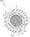
- FIGS. 1 and 2 a configuration of an optical fiber cable 10 according to a first embodiment will be described with reference to FIGS. 1 and 2 .
- the scale is appropriately changed in order to make it possible to recognize the shape of each component member.
- the optical fiber cable 10 is provided with a core 2, an inner sheath 3, a pair of wire bodies 4, a pair of tension members 7, a reinforcing sheet 5, and an outer sheath 6.
- the inner sheath 3, the reinforcing sheet 5, and the outer sheath 6 are formed in a tubular shape having a common center axis O.
- a direction along the center axis O is referred to as a longitudinal direction.
- a section orthogonal to the longitudinal direction is referred to as a cross section, and a section along the longitudinal direction is referred to as a longitudinal section.
- a direction orthogonal to the center axis O is referred to as a radial direction, and a direction revolving around the center axis O is referred to as a circumferential direction.
- the core 2 is formed by assembling a plurality of optical fibers 21.
- the core 2 is provided with a plurality of optical fiber units 23 each separately having the plurality of optical fibers 21, and a wrapping tube 24 wrapping these optical fiber units 23.
- each optical fiber unit 23 has twenty optical fibers 21, and the wrapping tube 24 wraps ten optical fiber units 23.
- the core 2 includes a total of 200 optical fibers 21. The number of the optical fibers 21 included in the core 2 may be appropriately changed.
- the wrapping tube 24 for example, a water absorbing tape may be used.
- a water absorbing tape may be used.
- the cross-sectional shape of the core 2 in the present embodiment is circular, it is not limited thereto, and the shape may be a non-circular shape such as an elliptical shape.
- the core 2 need not be provided with the wrapping tube 24.
- the optical fiber unit 23 is provided with, for example, twenty optical fibers 21 and a bundling material 22 for bundling these optical fibers 21.
- an optical fiber core wire, an optical fiber element wire, or the like can be used as the optical fiber 21, an optical fiber core wire, an optical fiber element wire, or the like.
- the optical fiber unit 23 is a so-called intermittent adhesive type.
- a core wire of intermittent adhesive tape when the bundle of the optical fibers 21 is pulled in a direction orthogonal to an extending direction thereof, the optical fibers 21 are adhered to each other so as to spread in a mesh shape (spider web shape).
- one optical fiber 21 is adhered to the optical fibers 21 on both sides thereof at different positions in the longitudinal direction.
- the adjacent optical fibers 21 are adhered to each other with a predetermined interval in the longitudinal direction.
- the aspect of the optical fiber 21 included in the core 2 is not limited to the core wire of intermittent adhesive tape and may be changed as appropriate.
- the inner sheath 3 has a role of accommodating the core 2 therein and protecting the core 2.
- polyolefin (PO) resins such as polyethylene (PE), polypropylene (PP), ethylene ethyl acrylate copolymer (EEA), ethylene vinyl acetate copolymer (EVA), and ethylene propylene copolymer (EP), polyvinyl chloride (PVC) or the like can be used.
- the thickness in the radial direction of the inner sheath 3 varies in the circumferential direction, and the thickness is the thinnest in a portion where the wire body 4 is embedded.
- the thickness in the radial direction of the inner sheath 3 is illustrated as follows.
- a thickness of a radially inner portion from the wire body 4 is illustrated as t i
- a thickness of a radially outer portion from the wire body 4 is illustrated as t o
- thicknesses of radially inner portions from a pair of tension members 7 is illustrated as T i
- thicknesses of radially outer portions from a pair of tension members 7 is illustrated as T o .
- the t i is 0.3 mm or less. t i need not be 0.3 mm or less over the entire length in the longitudinal direction of the inner sheath 3, and a portion of the longitudinal direction may be within this numerical value range.
- the wire body 4 may be embedded in the inner sheath 3 in a state where t i is 0 mm partially in the longitudinal direction, that is, the wrapping tube 24 and the wire body 4 are in contact with each other.
- t o is 0.3 mm or less. In order to prevent the inner sheath 3 from unexpectedly breaking, t i and t o are set so that neither are 0 mm.
- t o may be 0.1 to 0.3 mm and t i may be 0 mm.
- the thickness of the inner sheath 3 need not be within the above range over the entire length of the optical fiber cable 10, and may be within the above range at least in a portion of the longitudinal direction.
- the pair of wire bodies 4 are embedded in the inner sheath 3 and have a role of facilitating the operation of drawing out the core 2 from the inside of the inner sheath 3.
- the pair of wire bodies 4 extend in the longitudinal direction of the optical fiber cable 10.
- the pair of wire bodies 4 are disposed so as to interpose the core 2 in the radial direction. In addition, the pair of wire bodies 4 are disposed at equal intervals in the radial direction from the core 2. As a result, the wire body 4 is disposed at a position symmetrical with respect to the core 2.
- the number of the wire bodies 4 embedded in the inner sheath 3 may be 1 or 3 or more. In a case where 3 or more wire bodies 4 are embedded in the inner sheath 3, each of the wire bodies 4 are disposed at equal intervals in the radial direction and at equal intervals in the circumferential direction from the core 2. Accordingly, each of the wire bodies 4 can be disposed at a position symmetrical with respect to the core 2.
- the pair of tension members 7 are embedded in the inner sheath 3.
- the pair of tension members 7 extend in the longitudinal direction of the optical fiber cable 10.
- the pair of tension members 7 has a role of improving the strength in the longitudinal direction of the optical fiber cable 10.
- a material of the tension member 7 for example, a metal wire (steel wire or the like), a tension fiber (aramid fiber or the like), FRP or the like can be used.
- the pair of tension members 7 are disposed with the core 2 interposed in the radial direction.
- the pair of tension members 7 are disposed at equal intervals in the radial direction from the core 2.
- the position where the tension member 7 is disposed is symmetrical with the core 2 interposed therebetween. Accordingly, it is possible to suppress the occurrence of uneven stress in the optical fiber cable 10 due to, for example, a change in temperature, and to make it difficult for the optical fiber cable 10 to be twisted.
- the number of tension members 7 embedded in the inner sheath 3 may be 1 or 3 or more.
- each tension member 7 is disposed at equal intervals in the radial direction from the core 2 and at equal intervals from each other in the circumferential direction. Accordingly, these tension members can be disposed at symmetrical positions with respect to the core 2. For example, in a case where the number of tension members 7 is four, two of these are taken as a pair, and each of two pairs of tension members 7 may be embedded in the inner sheath 3 with the core 2 interposed therebetween.
- the pair of tension members 7 and a pair of wire bodies 4 are embedded in the inner sheath 3 so that intervals in the circumferential direction between the tension member 7 and the wire body 4 adjacent in the circumferential direction are equal to each other.
- the reinforcing sheet 5 covers the inner sheath 3 and the pair of wire bodies 4.
- the reinforcing sheet 5 has a role of protecting the core 2 from a flying object such as a bullet for hunting or feeding damage of animals.
- a corrugated iron tape can be used as the reinforcing sheet 5.
- nonwoven fabrics such as glass fibers and aramid fibers may be used, in addition to iron alloys such as stainless steel, and metals such as copper and copper alloys.
- a thermoplastic resin such as polyethylene, polypropylene, polyester, PBT, and Ny, or a thermosetting resin such as epoxy may be used as the reinforcing sheet 5.
- the thickness of the reinforcing sheet 5 may be, for example, 0.1 to 0.3 mm. By setting the thickness of the reinforcing sheet 5 within this range, it is possible to prevent the optical fiber 21 from being damaged due to feeding damage of animals, and to suppress the volume and weight of the entire optical fiber cable 10.
- the reinforcing sheet 5 of the present embodiment is molded in a tubular shape by longitudinally winding around the inner sheath 3.
- the reinforcing sheet 5 may be laterally wound or helically wound around the inner sheath 3.
- the outer sheath 6 covers the reinforcing sheet 5.
- PO resin such as PE, PP, EEA, EVA, and EP, or PVC can be used.
- a pair of protrusions (mark portions) 6a extending along the longitudinal direction is formed on the outer peripheral surface of the outer sheath 6, a pair of protrusions (mark portions) 6a extending along the longitudinal direction is formed.
- Each of the protrusions 6a is disposed on a portion of the outer peripheral surface of the outer sheath 6 where the pair of tension members 7 are positioned radially inward. Since the protrusion 6a is used for aligning the position of a tool K described later, other embodiments may be adopted. For example, instead of the protrusion 6a, a recessed portion recessed radially inward from the outer peripheral surface of the outer sheath 6 or a mark portion such as marking by paint may be adopted.
- Capsaicin or the like may be included in the material forming the outer sheath 6. In this case, for example, it is possible to prevent the animal such as a mouse from chewing the outer sheath 6.
- the thickness t i on the inner side of the wire body 4 in the inner sheath 3 is smaller than the thickness T i on the inner side of the tension member 7.
- the thickness t o on the outer side of the wire body 4 is smaller than the thickness T o on the outer side of the tension member 7. That is, t i ⁇ T i and t o ⁇ T o are satisfied.
- the tip end portion of the tool K such as a blade is aligned with the position of the protrusion 6a and the outer sheath 6 and the reinforcing sheet 5 are cut. At this time, the tip end portion of the tool K abuts against the tension member 7, and is prevented from entering further radially inward.
- the outer sheath 6 and the reinforcing sheet 5 are divided into two halves and have a semi-cylindrical shape.
- the outer sheath 6 and the reinforcing sheet 5 are pushed out radially outward, and the surface of the inner sheath 3 is visually observed or touched by hand. Accordingly, it is possible to ascertain the thickness t o portion of the inner sheath 3 where the wire body 4 is embedded. This t o portion can be easily broken by a claw or the like and the surface of the wire body 4 can be exposed from the broken portion. After exposing the wire body 4, the wire body 4 is deformed or the inner sheath 3 is deformed to draw out the wire body 4 radially outward. Accordingly, as illustrated in part (c) of FIG. 2 , the wire body 4 can be removed from the inner sheath 3.
- the optical fiber 21 is wound by the wrapping tube 24, since the wrapping tube 24 is a water absorbing tape or the like, it is easy to break and can be easily removed.
- An optical fiber cable 100 of a structure 1 in the related art illustrated in FIG. 11 is a so-called slot type optical fiber cable.
- the optical fiber cable 100 includes a slot rod 101, a plurality of optical fiber units 102 each having a plurality of optical fibers, a wrapping tube 103, a reinforcing sheet 104, and an outer sheath 105.
- the wrapping tube 103, the reinforcing sheet 104, and the outer sheath 105 are the same as each of the constituent members of the optical fiber cable 10 of the first embodiment illustrated in FIG. 1 .
- the wrapping tube 103 is removed and an optical fiber unit 102 accommodated in a groove portion of the slot rod 101 is drawn out.
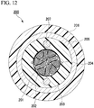
- An optical fiber cable 200 of a structure 2 in the related art illustrated in FIG. 12 is a so-called high-density type optical fiber cable.
- the optical fiber cable 200 is provided with a plurality of optical fiber units having a plurality of optical fibers 201, a wrapping tube 202, an inner sheath 203, a pair of rip cords 204, a reinforcing sheet 205, an outer sheath 206, and a pair of tension members 207.
- the wrapping tube 202, the inner sheath 203, the reinforcing sheet 205, the outer sheath 206, and the tension member 207 are the same as each of the constituent members of the optical fiber cable 10 of the first embodiment illustrated in FIG. 1 .
- the inner sheath 203 is cut and a pair of rip cords 204 is drawn out.
- the inner sheath 203, the reinforcing sheet 205, and the outer sheath 206 are torn by pulling the pair of rip cords 204 radially outward.
- the wrapping tube 202 is removed and the optical fiber 201 is drawn out.
- Table 1 illustrates the results of relative comparison of the outer diameter, the mass, and the draw-out-operation time for the optical fiber cable 100 (structure 1 in the related art), the optical fiber cable 200 (structure 2 in the related art), and the optical fiber cable 10 (first embodiment).
- "Draw-out-operation time” is the time required from drawing out the optical fiber from the inside of the cable within the range of 10 cm in the longitudinal direction, for example.
- the outer diameter and the mass of the optical fiber cables of the structure 2 in the related art and of the first embodiment are smaller than that of the structure 1 in the related art. This is because the optical fiber cable 100 of the structure 1 in the related art has the slot rod 101, whereas the optical fiber cables of the structure 2 in the related art and the first embodiment do not have such a slot rod. Since the constituent members of the structure 2 in the related art and the first embodiment are substantially the same as each other, these are equal to each other in the outer diameter and the mass.
- the structure 1 in the related art and the first embodiment are equal to each other, whereas the structure 2 in the related art is longer by 50% or more. The reason for this will be described below.
- the outer sheath 206 and the reinforcing sheet 205 are cut, and the inner sheath 203 is further cut. In this manner, since the step of using the tool is twice, the operation time is prolonged.
- the operation time is relatively short.
- the thickness t o of the inner sheath 3 on the outer side of the wire body 4 is small, the portion where the wire body 4 is embedded can be easily confirmed by visually observing or touching the inner sheath 3 by hand. Furthermore, this t o portion can be easily broken by a claw or the like, and the surface of the wire body 4 can be exposed from the broken portion.
- the wire body 4 can be easily drawn out from the inner sheath 3. Since the thickness t i of the inner sheath 3 on the inner side of the wire body 4 is small, it is possible to easily tear the inner sheath 3 from this portion as a starting point and draw out the optical fiber 21.
- the core 2 is accommodated in the inner sheath 3, it is possible to prevent accidental cutting of the optical fiber 21 when cutting the outer sheath 6 and the reinforcing sheet 5 as compared with a case where the core 2 is not accommodated in the inner sheath 3.
- optical fiber cable 10 of the first embodiment it is possible to reduce the number of times of use of the tool for cutting and to easily perform the draw-out-operation without requiring a large force.
- the protrusions 6a are disposed on each of the portions of the outer peripheral surface of the outer sheath 6 where the pair of tension members 7 are positioned radially inward. Therefore, when cutting the outer sheath 6 and the reinforcing sheet 5, the position of the tool such as a blade in the circumferential direction can be easily adjusted to the position of the tension member 7. As a result, when the outer sheath 6 and the reinforcing sheet 5 are cut, the tool abuts against the tension member 7, so that it is possible to prevent the tool from reaching the optical fiber 21 disposed radially inward from the tension member 7 and erroneously cutting the optical fiber 21.
- a portion of the inner sheath 3 outside the wire body 4 can be easily torn by a claw or the like.
- the portion of the inner sheath 3 in which the wire body 4 is embedded can be easily broken by a claw or the like to draw out the wire body 4 from the inner sheath 3.
- the inner sheath 3 naturally breaks and the wrapping tube 24 can be exposed.
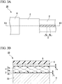
- the configurations of the wire body 4 and the inner sheath 3 are different from those of the first embodiment.
- the wire body 4 in the second embodiment is formed of a yarn obtained by twisting fibers such as PP and polyester.
- the wire body 4 is formed by further twisting a plurality of element wires 4a which are yarns.
- FIG. 3A is an explanatory view illustrating a configuration of the optical fiber cable 20 according to the second embodiment, and illustration of each configuration is partially omitted. Specifically, the outer sheath 6 and the reinforcing sheet 5 are not illustrated on the central portion, and the outer sheath 6, the reinforcing sheet 5, and the inner sheath 3 are not illustrated on the right portion in the lateral direction in FIG. 3A .
- FIG. 3B is a sectional view taken along arrow X-X in FIG. 3A .
- the optical fiber unit 23 is indicated by hatching.
- the position in the radial direction on the surface of the wire body 4 periodically varies along the longitudinal direction.
- the inner sheath 3 is covered on the surface of the wire body 4 so that the thickness t o on the outer side of the wire body 4 is substantially constant. As a result, the unevenness is formed on the surface of the inner sheath 3 along the longitudinal direction.
- the inner thickness t i of the wire body 4 of the inner sheath 3 periodically varies along the longitudinal direction.
- the minimum value of the thickness t i of the inside of the wire body 4 is 0.1 to 0.3 mm.
- Table 2 illustrates the results of relative comparison of the outer diameter, the mass, and the draw-out-operation time for the optical fiber cable 100 (structure 1 in the related art), the optical fiber cable 10 (first embodiment), and the optical fiber cable 20 (second embodiment).
- a nylon rod was used as the wire body 4 of the optical fiber cable 10
- a yarn obtained by twisting PP fibers was used as the wire body 4 of the optical fiber cable 20.
- the other conditions are the same as the comparative experiment illustrated in Table 1.
- the outer diameter and the mass are equal to each other. This is because the difference between the first embodiment and the second embodiment is only the form of the wire body 4 and the inner sheath 3.
- the draw-out-operation time is reduced by 20% or more in the second embodiment compared to the first embodiment. This is because it is possible to more easily recognize the portion of the inner sheath 3 in which the wire body 4 is embedded by visually observing or touching by hand, since the unevenness along the longitudinal direction is formed on the surface of the inner sheath 3. Furthermore, this is because the step of drawing out the wire body 4 from the inner sheath 3 becomes easier, since the yarn rich in flexibility is used as the wire body 4 of the second embodiment.
- the unevenness along the longitudinal direction is formed on the surface of the inner sheath 3. Therefore, by observing visually or touching by hand, it is possible to easily recognize the portion of the inner sheath 3 in which the wire body 4 is embedded.
- the thickness t o of the inner sheath 3 on the outer side of the wire body 4 is constant, and this value of t o may vary along the longitudinal direction.
- the thickness t o of the inner sheath 3 on the outer side of the wire body 4 may periodically vary along the longitudinal direction.
- An optical fiber cable 30 of the third embodiment illustrated in FIG. 5 differs from the first embodiment in that the wire body 4 is fixed to the reinforcing sheet 5.
- the wire body 4 of the third embodiment is fixed to the reinforcing sheet 5 through a fixing portion 8 and a fixing layer 9.
- the fixing portion 8 is formed of, for example, an adhesive.
- the fixing layer 9 is formed, for example, by bonding a PET sheet to the inner peripheral surface of the reinforcing sheet 5 with the adhesive.
- the fixing layer 9 is formed over the entire inner peripheral surface of the reinforcing sheet 5.
- the fixing portion 8 and the fixing layer 9 are not fixed to the inner sheath 3.
- Table 3 illustrates the results of relative comparison of the outer diameter, the mass, and the draw-out-operation time for the optical fiber cable 100 (structure 1 in the related art), the optical fiber cable 10 (first embodiment), the optical fiber cable 20 (second embodiment), and the optical fiber cable 30 (third embodiment).
- the draw-out-operation time of the third embodiment is reduced by approximately 30% compared to the first embodiment.
- the wire body 4 is fixed to the reinforcing sheet 5 by the fixing portion 8 and the fixing layer 9. Therefore, as the reinforcing sheet 5 is cut and pushed out radially outward, the wire body 4 is drawn out from the inner sheath 3.
- the PET sheet as the fixing layer 9 is disposed between the reinforcing sheet 5 and the inner sheath 3 in a state of being adhered and fixed to the reinforcing sheet 5 and not fixed to the inner sheath 3. Therefore, the reinforcing sheet 5 is easily separated from the inner sheath 3 radially outward.
- the draw-out-operation time is shorter than that of the optical fiber cable 10 of the first embodiment.
- the wire body 4 is fixed to the reinforcing sheet 5
- the wire body 4 is drawn out from the inner sheath 3 as the outer sheath 6 and the reinforcing sheet 5 are cut and pushed out radially outward.
- it is not necessary to draw out the wire body 4 from the inner sheath 3, and it is possible to make the draw-out-operation more efficient.
- the adhesive is used as the fixing portion 8 and the PET sheet is used as the fixing layer 9, and the present invention is not limited thereto.
- a portion of the reinforcing sheet 5 in the circumferential direction protrudes in a hook shape radially inward, and the wire body 4 is engaged with the protrusion portion with the hook shape. Accordingly, the wire body 4 and the reinforcing sheet 5 may be fixed to each other.
- the reinforcing sheet 5 to which the wire body 4 is fixed may be longitudinally wound around the core 2, and the inner sheath 3 may be molded by injecting molten resin or the like between the core 2 and the reinforcing sheet 5.
- an optical fiber cable 40 of the fourth embodiment differs from the first embodiment in that the core 2 is disposed eccentrically with respect to the center axis O, and the thickness of the inner sheath 3 in the radial direction is uneven in the circumferential direction.
- the thickness with the smaller thickness is denoted by t i1
- the thickness with the larger thickness is denoted by t i2 .
- FIG. 7 is an explanatory view extracting a step of the draw-out operation in the optical fiber cable 40 of the fourth embodiment.
- the step of cutting the outer sheath 6 and the reinforcing sheet 5 with a tool is not repeated since the step is the same as parts (a) and (b) of FIG. 2 .
- the portion of the inner sheath 3 having the thickness t i1 is broken. At this time, the stress due to the tension tends to concentrate on the portion having the thickness t i1 , so that the inner sheath 3 can be torn more easily.
- Table 4 illustrates the results of comparing the draw-out operation time with the optical fiber cable 10 of the first embodiment by changing the magnitudes of t i1 and t i2 in three steps for the optical fiber cable 40 of the fourth embodiment.
- the inner sheath ratio of the wire body illustrated in Table 4 illustrates a ratio (t i2 /t i1 ) of t i2 with respect to t i1 .
- the value of t i2 /t i1 was changed to 1.5 (fourth embodiment 1), 2.5 (fourth embodiment 2), and 3.0 (fourth embodiment 3).
- the magnitude of t i1 was changed to 0.3 mm (fourth embodiment 1) and 0.2 mm (fourth embodiment 2 and 3).
- the draw-out operation time of the optical fiber cable 40 of the fourth embodiment is shorter than that of the optical fiber cable 10 of the first embodiment by 30% or more. This is due to the following reason.
- the stress due to the tension is likely to concentrate on the portion t i1 having a thickness smaller than t i2 of the inner sheath 3. Therefore, it is possible to break the inner sheath 3 more easily, and the draw-out-operation time is shortened.
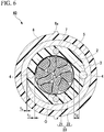
- An optical fiber cable 50 of the fifth embodiment is different from the first embodiment in that the configuration of the inner sheath 3 is changed without disposing the wire body 4.
- the wire body 4 is not embedded in the inner sheath 3 of the optical fiber cable 50 of the fifth embodiment.
- the inner sheath 3 is formed of a V-shaped groove portion (notch) 3b extending radially inward from the outer peripheral surface thereof. The width of the groove portion 3b gradually decreases in the circumferential direction inward radially.
- a pair of groove portions 3b are formed on the outer peripheral surface of the inner sheath 3 with the core 2 interposed therebetween.
- the thickness t i in the radial direction at the portion adjacent to the bottom of the groove portion 3b is 0.1 to 0.3 mm.
- the optical fiber cable 50 of the fifth embodiment when the inner sheath 3 is pulled in the vertical direction in FIG. 8 , stress due to pulling is concentrated on the bottom of the groove portion 3b. As a result, the inner sheath 3 can be easily torn with the groove portion 3b as a starting point, and the optical fiber 21 can be drawn out.
- the shape of the groove portion 3b is not limited to the V-shape, and other shapes may be adopted as long as stress concentrates on the bottom thereof.
- the shape may be a U-shaped groove portion 3b which is recessed radially inwardly from the outer peripheral surface of the inner sheath 3 and has two corner portions in the cross section.
- a notch extending in the longitudinal direction may be provided on the outer peripheral surface of the inner sheath 3, and the notch may be formed as the groove portion 3b.
- one or three or more groove portions 3b may be formed on the outer peripheral surface of the inner sheath 3.
- An optical fiber cable 60 of the sixth embodiment differs from the first embodiment in that an opening 3a is formed on the outer peripheral surface of the inner sheath 3 and a portion of the surface of the wire body 4 is exposed to the outside through the opening 3a.
- the thickness t o of the inner sheath 3 on the inner side of the wire body 4 in the first embodiment is zero, the thickness is equal to the present embodiment.
- the thickness t i on the inner side of the wire body 4 in the present embodiment is set to be larger than 0 mm in order to prevent the inner sheath 3 from unexpectedly breaking.
- a pair of openings 3a are formed on the outer peripheral surface of the inner sheath 3 of the present embodiment.
- Each opening 3a extends over the entire length in the longitudinal direction of the inner sheath 3.
- each of the portions of the surfaces of the pair of wire bodies 4 is exposed to the outside of the inner sheath 3.
- the fact of "exposed to the outside” is not limited to a state where the wire body 4 is partially present in a space radially outside the outer peripheral surface of the inner sheath 3.
- it also includes a state where the entire of the wire body 4 is present radially inside the outer peripheral surface of the inner sheath 3 and the wire body 4 is visible from the outside of the inner sheath 3 through the opening 3a.
- the opening 3a is formed on the outer peripheral surface of the inner sheath 3 in which the wire body 4 is embedded, and the wire body 4 can be visually recognized from the outside of the inner sheath 3 through the opening 3a. Therefore, when the outer sheath 6 and the reinforcing sheet 5 are cut, the wire body 4 can be easily drawn out from the inner sheath 3. Since the portion of the inner sheath 3 having the thickness t i on the inner side of the wire body 4 is thin, it is possible to draw out the optical fiber 21 easily by tearing the inner sheath 3 from this portion of t i as a starting point.
- approximately 3/4 of the diameter of the wire body 4 is positioned inside the inner sheath 3, and the remaining approximately 1/4 thereof is positioned outside the inner sheath 3.
- the proportion of the portion of the wire body 4 positioned inside the inner sheath 3 is not limited to the above and may be changed as appropriate.
- the optical fiber cable provided with the tension member 7 has been described. Accordingly, for example, the strength against the tension of the optical fiber cable may be secured by using the wire body 4 or the reinforcing sheet 5 without using the tension member 7.
- the protrusion 6a may be formed on a portion of the outer peripheral surface of the outer sheath 6 where the wire body 4 is positioned radially inward.
- the wire body 4 and the tension member 7 are disposed at symmetrical positions with respect to the core 2, and the present invention is not limited thereto. Accordingly, these members 4 and 7 may be disposed at asymmetrical positions with respect to the core 2 in cross-sectional view.
- the thickness t i of the inside of the wire body 4 in the inner sheath 3 is 0.3 mm or less, and the thickness is not limited thereto. Accordingly, other thickness may be used as long as it can be easily torn by hand.
- the V-shaped groove portion 3b is formed in the inner sheath 3, and the stress is likely to concentrate more when the inner sheath 3 is pulled than in the other embodiments, so that the thickness t i of the inside of the wire body 4 may be 0.3 mm or more.
- a yarn obtained by twisting fibers as the wire body 4 may be used, and the wire body 4 may be fixed to the reinforcing sheet 5 via the fixing portion 8 and the fixing layer 9.
- the adhesive as the fixing portion 8, the adhesive can be infiltrated between fibers of the wire body 4, and the wire body 4 and the reinforcing sheet 5 can be adhered more firmly to each other.
- the groove portion 3b in which the width in the circumferential direction gradually decreases radially inward may be formed in the inner sheath 3 after the wire body 4 has been removed. In this case, it is possible to easily form the groove portion 3b on the outer peripheral surface of the inner sheath 3.
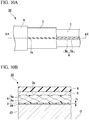
- FIGS. 10A and 10B may be adopted.
- the plurality of openings 3a are formed at equal intervals in the longitudinal direction on the surface of the inner sheath 3.
- the surface of the wire body 4 is exposed to the outside of the inner sheath 3 through the plurality of openings 3a.
- the position in the radial direction on the outer peripheral surface of the inner sheath 3 in the longitudinal sectional view is substantially uniform along the longitudinal direction.
- the position in the radial direction on the surface of the wire body 4 periodically varies along the longitudinal direction, and the radially outer portion and the radially inner portion on the outer peripheral surface of the inner sheath 3 are alternately arranged in the longitudinal direction.
- each opening 3a is suppressed small, for example, even when the inner sheath 3 is immersed in a liquid and cooled during manufacturing the optical fiber cable 20, it is difficult for liquid to enter through the opening 3a.
- a yarn obtained by twisting fibers as the wire body 4
- the inner sheath 3 is unlikely to break unexpectedly, as compared with a case where an opening 3a is formed without a cut line along the longitudinal direction, for example.
- the inner sheath 3 is unexpectedly broken to expose the core 2, and it is possible to prevent the optical fiber 21 from being injured.
- optical fiber cable first to sixth embodiment
- 2 core
- 3 inner sheath
- 3a opening
- 4 wire body
- 4a element wire
- 5 reinforcing sheet
- 6 outer sheath
- 6a protrusion (mark portion)
- 7 tension member
- 100 optical fiber cable (structure 1 in the related art)
- 200 optical fiber cable (structure 2 in the related art)
Landscapes
- Physics & Mathematics (AREA)
- General Physics & Mathematics (AREA)
- Optics & Photonics (AREA)
- Engineering & Computer Science (AREA)
- Manufacturing & Machinery (AREA)
- Light Guides In General And Applications Therefor (AREA)
- Insulated Conductors (AREA)
Abstract
Description
- The present invention relates to an optical fiber cable.
- Priority is claimed on Japanese Patent Application No.
2016-153695, filed on August 4, 2016 - An optical fiber cable installed, laid, or embedded (hereinafter simply referred to as "installed") in a mountain or a forest may be bitten by a wild animal such as a mouse, a squirrel, or a woodpecker, or be hit by a flying object such as a bullet used in hunting. In such a case, an optical fiber inside the optical fiber cable may be damaged. In order to prevent such damage, the optical fiber cable disclosed in
PTL 1 is protected by covering the optical fiber with a reinforcing sheet. - In an optical fiber cable having a reinforcing sheet, when disassembling or connecting the optical fiber after installation, the operation of cutting the reinforcing sheet or the like and drawing out the optical fiber from the inside (hereinafter referred to as "draw-out-operation") is complicated, and the operation time is prolonged. In addition, there is a case where the optical fiber is unexpectedly cut when cutting the reinforcing sheet.
- On the other hand, an optical fiber cable of
PTL 2 is provided with a core formed by assembling a plurality of optical fibers, an inner sheath accommodating the core therein, a rip cord disposed inside the inner sheath, a reinforcing sheet covering the inner sheath, and an outer sheath covering the reinforcing sheet. In this configuration, after removing the outer sheath and the reinforcing sheet with a tool such as a blade, the inner sheath is torn by the tool and the rip cord is drawn out. Since the inner sheath, a metal tape, and the outer sheath are torn by the rip cord, it is possible to shorten the draw-out-operation time while preventing unexpected cutting of the optical fiber. -
- [PTL 1] Japanese Unexamined Patent Application, First Publication No.
H6-174985 - [PTL 2] Japanese Unexamined Patent Application, First Publication No.
2013-228567 - When performing the draw-out-operation on the optical fiber cable of
PTL 2, it is necessary to use the tool twice at the time of cutting the outer sheath and the reinforcing sheet and at the time of cutting the inner sheath. Furthermore, when tearing the reinforcing sheet or the outer sheath using the rip cord, a large force is required. - Therefore, there is a need for an optical fiber cable whereby a draw-out-operation can be more easily performed.
- The present invention has been made in view of the above problems, and an object thereof is to provide an optical fiber cable whereby a draw-out-operation can be easily performed while protecting the optical fiber with a reinforcing sheet.
- In order to solve the above problem, an optical fiber cable according to the first aspect of the present invention includes a core including gathered optical fibers, an inner sheath that accommodates the core therein, a wire body embedded in the inner sheath, a pair of tension members embedded in the inner sheath with the core interposed therebetween, a reinforcing sheet that covers the inner sheath and the wire body, and an outer sheath that covers the reinforcing sheet, in which in the inner sheath, when a thickness of a radially inner portion from the wire body is ti, a thickness of a radially inner portion from the pair of tension members is Ti, a thickness of a radially outer portion from the wire body is to, a thickness of a radially outer portion from the pair of tension members is To, ti < Ti and to < To are satisfied.
- According to the optical fiber cable of the first aspect, in the inner sheath, the thickness to of the radially outer portion of the wire body is small, so that when the outer sheath and the reinforcing sheet are cut, the wire body can be easily drawn out from the inner sheath. For example, in a case where to is set to 0.3 mm or less, the portion of to can be easily broken with a claw or the like.
- Since the thickness ti of the radially inner portion of the portion of the inner sheath in which the wire body is embedded is small, it is possible to draw out the optical fiber by easily tearing the inner sheath from the portion of ti as a starting point.
- In addition, since the core is accommodated in the inner sheath, it is possible to prevent accidental cutting of the optical fiber when cutting the outer sheath and the reinforcing sheet, for example, as compared with a case where the core is not accommodated in the inner sheath.
- As described above, according to the above aspect, it is possible to reduce the number of times of use of the tool for cutting, and to easily perform the draw-out-operation without requiring a large force.
- In the optical fiber cable according to the second aspect of the present invention, a pair of the wire bodies is disposed with the core interposed therebetween in the optical fiber cable according to the first aspect.
- According to the second aspect, in the cross-sectional view of the optical fiber cable, the position where the wire body is disposed is symmetrical with the core interposed therebetween. Accordingly, it is possible to suppress the occurrence of uneven stress in the optical fiber cable due to, for example, a change in temperature, and to make it difficult for the optical fiber cable to be twisted.
- In the optical fiber cable according to the third aspect of the present invention, in an outer peripheral surface of the outer sheath, mark portions are each disposed in portions where the pair of tension members are positioned radially inward in the optical fiber cable according to the first or second aspect.
- According to the third aspect, when cutting the outer sheath and the reinforcing sheet, by aligning the position in a circumferential direction of the tool such as a blade with the mark portion, the position of the tool can be easily adjusted to the position of the tension member. As a result, the tool abuts against the tension member when cutting the outer sheath and the reinforcing sheet. Therefore, it is possible to prevent the tool from reaching the optical fiber disposed radially inward of the tension member, erroneously cutting the optical fiber.
- In the optical fiber cable according to the fourth aspect of the present invention, a portion of a surface of the wire body is exposed to an outside of the inner sheath through an opening formed in an outer peripheral surface of the inner sheath, in the optical fiber cable according to any one of the first to third aspects.
- According to the fourth aspect, the opening is formed in the outer peripheral surface of the inner sheath, and the wire body can be visually recognized from the outside of the inner sheath through the opening. Therefore, it is likely to further draw out the wire body from the inner sheath, and the draw-out-operation can be performed more easily.
- In the optical fiber cable according to the fifth aspect of the present invention, a portion of the wire body is fixed to the reinforcing sheet in the optical fiber cable according to the fourth aspect.
- According to the fifth aspect, when the reinforcing sheet is deformed to open after the outer sheath and the reinforcing sheet is cut, the wire body fixed to the reinforcing sheet is also moved. As a result, the wire body is naturally drawn out from the inner sheath and the draw-out-operation can be made more efficient.
- In the optical fiber cable according to the sixth aspect of the present invention, a plurality of the openings are formed on the outer peripheral surface of the inner sheath at intervals in a longitudinal direction, and the surface of the wire body is exposed to the outside of the inner sheath through the plurality of the openings, in the optical fiber cable according to the fourth or fifth aspect.
- According to the sixth aspect, it is possible to reduce the area of each opening, as compared with a case where an opening is formed without a cut line along the longitudinal direction, for example. As a result, in the operation of removing the outer sheath and the reinforcing sheet, the inner sheath is unexpectedly broken to expose the core, and it is possible to prevent the optical fiber from being injured.
- In the optical fiber cable according to the seventh aspect of the present invention, the wire body is formed by twisting a plurality of element wires, in the optical fiber cable according to any one of the first to sixth aspects.
- According to the seventh aspect, flexibility of the entire wire body can be improved while maintaining the strength in the longitudinal direction of the wire body. As a result, it is possible to further facilitate the step of drawing out the wire body from the inner sheath.
- Furthermore, in the longitudinal sectional view of the optical fiber cable, the position in the radial direction of the surface of the wire body periodically varies along the longitudinal direction. As a result, the plurality of openings are formed at intervals in the longitudinal direction on the outer peripheral surface of the inner sheath, and it is possible to easily realize the optical fiber cable in which the wire body is exposed to the outside of the inner sheath through the plurality of openings.
- In the optical fiber cable according to the eighth aspect of the present invention, 0.1 [mm] ≤ ti ≤ 0.3 [mm] is satisfied, in the optical fiber cable according to any one of the first to seventh aspects.
- According to the eighth aspect, the thickness ti of the inner sheath in the radially inner portion from the wire body is thin enough to easily break by hand, for example. Therefore, after the wire body is drawn out, the inner sheath can be broken more easily and the draw-out-operation can be performed more efficient.
- In the optical fiber cable according to the ninth aspect of the present invention, to ≤ 0.3 [mm] is satisfied, in the optical fiber cable according to any one of the first to eighth aspects.
- According to the ninth aspect, the thickness to of the outer peripheral portion of the inner sheath in the portion where the wire body is embedded is thin enough to easily break the outer peripheral portion with a claw or the like. Therefore, the wire body can be easily drawn out from the inner sheath.
- In the optical fiber cable according to the tenth aspect of the present invention, 0.1 [mm] ≤ to ≤ 0.3 [mm] and ti=0 [mm] are satisfied, in the optical fiber cable according to any one of the first to ninth aspects.
- According to the tenth aspect, since the thickness of the radially outer portion from the wire body in the inner sheath is 0.1 to 0.3 mm, the portion of the inner sheath in which the wire body is embedded can be easily broken by the claw or the like and the wire body can be drawn out from the inner sheath. In addition, since the thickness of the radially inner portion from the wire body is 0 mm, when the wire body is drawn out from the inner sheath, the inner sheath naturally breaks to expose the core.
- Furthermore, since the thickness of the radially inner portion from the wire body in the inner sheath is 0 mm, it is possible to cover the core with the inner sheath in a state where the wire body is in contact with the core, and the optical fiber cable is manufactured more easily.
- An optical fiber cable according to the eleventh aspect of the present invention includes a core including gathered optical fibers, an inner sheath that accommodates the core therein, a pair of tension members embedded in the inner sheath with the core interposed therebetween, a reinforcing sheet that covers the inner sheath, and an outer sheath that covers the reinforcing sheet, in which the inner sheath is formed with a groove portion extending radially inward from an outer peripheral surface of the inner sheath.
- According to the eleventh aspect, when the inner sheath is pulled in the radial direction, the stress due to the pulling is concentrated on the groove portion formed in the outer peripheral surface of the inner sheath. As a result, the inner sheath can be easily torn with the groove portion as a starting point, and the optical fiber can be drawn out.
- According to the above aspect of the present invention, it is possible to provide the optical fiber cable that can easily perform the draw-out-operation while protecting the optical fiber with the reinforcing sheet.
-
-
FIG. 1 is a cross-sectional view illustrating a structure of an optical fiber cable according to a first embodiment. -
FIG. 2 is an explanatory view illustrating a step during a draw-out-operation of the optical fiber cable illustrated inFIG. 1 . -
FIG. 3A is an explanatory view illustrating a structure of an optical fiber cable according to a second embodiment. -
FIG. 3B is a sectional view taken along arrow X-X inFIG. 3A . -
FIG. 4A is an explanatory view illustrating a structure of an optical fiber cable according to a modified example of the embodiment illustrated inFIG. 3A . -
FIG. 4B is a sectional view taken along arrow X-X inFIG. 4A . -
FIG. 5 is a cross-sectional view illustrating a structure of an optical fiber cable according to a third embodiment. -
FIG. 6 is a cross-sectional view illustrating a structure of an optical fiber cable according to a fourth embodiment. -
FIG. 7 is an explanatory view illustrating a step during a draw-out-operation of the optical fiber cable illustrated inFIG. 6 . -
FIG. 8 is a cross-sectional view illustrating a structure of an optical fiber cable according to a fifth embodiment. -
FIG. 9 is a cross-sectional view illustrating a structure of an optical fiber cable according to a sixth embodiment. -
FIG. 10A is an explanatory view illustrating a structure of an optical fiber cable according to another embodiment. -
FIG. 10B is a sectional view taken along arrow X-X inFIG. 10A . -
FIG. 11 is a cross-sectional view illustrating a structure of a slot type optical fiber cable in the related art (structure 1 in the related art). -
FIG. 12 is a cross-sectional view illustrating a structure of a high density type optical fiber cable in the related art (structure 2 in the related art). - Hereinafter, a configuration of an
optical fiber cable 10 according to a first embodiment will be described with reference toFIGS. 1 and2 . In the drawings used in the following description, the scale is appropriately changed in order to make it possible to recognize the shape of each component member. - As illustrated in
FIG. 1 , theoptical fiber cable 10 is provided with acore 2, aninner sheath 3, a pair ofwire bodies 4, a pair oftension members 7, a reinforcingsheet 5, and anouter sheath 6. - In the present embodiment, the
inner sheath 3, the reinforcingsheet 5, and theouter sheath 6 are formed in a tubular shape having a common center axis O. - In the present embodiment, a direction along the center axis O is referred to as a longitudinal direction. In addition, a section orthogonal to the longitudinal direction is referred to as a cross section, and a section along the longitudinal direction is referred to as a longitudinal section. In addition, in a cross-sectional view, a direction orthogonal to the center axis O is referred to as a radial direction, and a direction revolving around the center axis O is referred to as a circumferential direction.
- The
core 2 is formed by assembling a plurality ofoptical fibers 21. Thecore 2 is provided with a plurality ofoptical fiber units 23 each separately having the plurality ofoptical fibers 21, and a wrappingtube 24 wrapping theseoptical fiber units 23. In the example ofFIG. 1 , eachoptical fiber unit 23 has twentyoptical fibers 21, and the wrappingtube 24 wraps tenoptical fiber units 23. As a result, thecore 2 includes a total of 200optical fibers 21. The number of theoptical fibers 21 included in thecore 2 may be appropriately changed. - As the wrapping
tube 24, for example, a water absorbing tape may be used. Although the cross-sectional shape of thecore 2 in the present embodiment is circular, it is not limited thereto, and the shape may be a non-circular shape such as an elliptical shape. Thecore 2 need not be provided with the wrappingtube 24. - The
optical fiber unit 23 is provided with, for example, twentyoptical fibers 21 and a bundlingmaterial 22 for bundling theseoptical fibers 21. As theoptical fiber 21, an optical fiber core wire, an optical fiber element wire, or the like can be used. Theoptical fiber unit 23 is a so-called intermittent adhesive type. In a core wire of intermittent adhesive tape, when the bundle of theoptical fibers 21 is pulled in a direction orthogonal to an extending direction thereof, theoptical fibers 21 are adhered to each other so as to spread in a mesh shape (spider web shape). Specifically, oneoptical fiber 21 is adhered to theoptical fibers 21 on both sides thereof at different positions in the longitudinal direction. Furthermore, the adjacentoptical fibers 21 are adhered to each other with a predetermined interval in the longitudinal direction. - The aspect of the
optical fiber 21 included in thecore 2 is not limited to the core wire of intermittent adhesive tape and may be changed as appropriate. - The
inner sheath 3 has a role of accommodating thecore 2 therein and protecting thecore 2. As the material of theinner sheath 3, polyolefin (PO) resins such as polyethylene (PE), polypropylene (PP), ethylene ethyl acrylate copolymer (EEA), ethylene vinyl acetate copolymer (EVA), and ethylene propylene copolymer (EP), polyvinyl chloride (PVC) or the like can be used. - In the cross-sectional view, the thickness in the radial direction of the
inner sheath 3 varies in the circumferential direction, and the thickness is the thinnest in a portion where thewire body 4 is embedded. In the present embodiment, the thickness in the radial direction of theinner sheath 3 is illustrated as follows. In theinner sheath 3, a thickness of a radially inner portion from thewire body 4 is illustrated as ti a thickness of a radially outer portion from thewire body 4 is illustrated as to, thicknesses of radially inner portions from a pair oftension members 7 is illustrated as Ti, and thicknesses of radially outer portions from a pair oftension members 7 is illustrated as To. - In the present embodiment, the ti is 0.3 mm or less. ti need not be 0.3 mm or less over the entire length in the longitudinal direction of the
inner sheath 3, and a portion of the longitudinal direction may be within this numerical value range. In addition, thewire body 4 may be embedded in theinner sheath 3 in a state where ti is 0 mm partially in the longitudinal direction, that is, the wrappingtube 24 and thewire body 4 are in contact with each other. - In the present embodiment, to is 0.3 mm or less. In order to prevent the
inner sheath 3 from unexpectedly breaking, ti and to are set so that neither are 0 mm. - For example, to may be 0.1 to 0.3 mm and ti may be 0 mm. The thickness of the
inner sheath 3 need not be within the above range over the entire length of theoptical fiber cable 10, and may be within the above range at least in a portion of the longitudinal direction. - The pair of
wire bodies 4 are embedded in theinner sheath 3 and have a role of facilitating the operation of drawing out thecore 2 from the inside of theinner sheath 3. The pair ofwire bodies 4 extend in the longitudinal direction of theoptical fiber cable 10. As thewire body 4, a cylindrical rod made of PP, nylon, or the like can be used. - The pair of
wire bodies 4 are disposed so as to interpose thecore 2 in the radial direction. In addition, the pair ofwire bodies 4 are disposed at equal intervals in the radial direction from thecore 2. As a result, thewire body 4 is disposed at a position symmetrical with respect to thecore 2. The number of thewire bodies 4 embedded in theinner sheath 3 may be 1 or 3 or more. In a case where 3 ormore wire bodies 4 are embedded in theinner sheath 3, each of thewire bodies 4 are disposed at equal intervals in the radial direction and at equal intervals in the circumferential direction from thecore 2. Accordingly, each of thewire bodies 4 can be disposed at a position symmetrical with respect to thecore 2. - The pair of
tension members 7 are embedded in theinner sheath 3. The pair oftension members 7 extend in the longitudinal direction of theoptical fiber cable 10. The pair oftension members 7 has a role of improving the strength in the longitudinal direction of theoptical fiber cable 10. As a material of thetension member 7, for example, a metal wire (steel wire or the like), a tension fiber (aramid fiber or the like), FRP or the like can be used. - The pair of
tension members 7 are disposed with thecore 2 interposed in the radial direction. In addition, the pair oftension members 7 are disposed at equal intervals in the radial direction from thecore 2. As a result, in the cross-sectional view, the position where thetension member 7 is disposed is symmetrical with thecore 2 interposed therebetween. Accordingly, it is possible to suppress the occurrence of uneven stress in theoptical fiber cable 10 due to, for example, a change in temperature, and to make it difficult for theoptical fiber cable 10 to be twisted. - The number of
tension members 7 embedded in theinner sheath 3 may be 1 or 3 or more. - In a case where 3 or
more tension members 7 are embedded in theinner sheath 3, eachtension member 7 is disposed at equal intervals in the radial direction from thecore 2 and at equal intervals from each other in the circumferential direction. Accordingly, these tension members can be disposed at symmetrical positions with respect to thecore 2. For example, in a case where the number oftension members 7 is four, two of these are taken as a pair, and each of two pairs oftension members 7 may be embedded in theinner sheath 3 with thecore 2 interposed therebetween. - In the present embodiment, the pair of
tension members 7 and a pair ofwire bodies 4 are embedded in theinner sheath 3 so that intervals in the circumferential direction between thetension member 7 and thewire body 4 adjacent in the circumferential direction are equal to each other. - The reinforcing
sheet 5 covers theinner sheath 3 and the pair ofwire bodies 4. The reinforcingsheet 5 has a role of protecting thecore 2 from a flying object such as a bullet for hunting or feeding damage of animals. As the reinforcingsheet 5, for example, a corrugated iron tape can be used. As a material of the reinforcingsheet 5, nonwoven fabrics such as glass fibers and aramid fibers may be used, in addition to iron alloys such as stainless steel, and metals such as copper and copper alloys. Alternatively, a thermoplastic resin such as polyethylene, polypropylene, polyester, PBT, and Ny, or a thermosetting resin such as epoxy may be used as the reinforcingsheet 5. The thickness of the reinforcingsheet 5 may be, for example, 0.1 to 0.3 mm. By setting the thickness of the reinforcingsheet 5 within this range, it is possible to prevent theoptical fiber 21 from being damaged due to feeding damage of animals, and to suppress the volume and weight of the entireoptical fiber cable 10. - The reinforcing
sheet 5 of the present embodiment is molded in a tubular shape by longitudinally winding around theinner sheath 3. The reinforcingsheet 5 may be laterally wound or helically wound around theinner sheath 3. - The
outer sheath 6 covers the reinforcingsheet 5. As the material of theouter sheath 6, PO resin such as PE, PP, EEA, EVA, and EP, or PVC can be used. - On the outer peripheral surface of the
outer sheath 6, a pair of protrusions (mark portions) 6a extending along the longitudinal direction is formed. Each of theprotrusions 6a is disposed on a portion of the outer peripheral surface of theouter sheath 6 where the pair oftension members 7 are positioned radially inward. Since theprotrusion 6a is used for aligning the position of a tool K described later, other embodiments may be adopted. For example, instead of theprotrusion 6a, a recessed portion recessed radially inward from the outer peripheral surface of theouter sheath 6 or a mark portion such as marking by paint may be adopted. - Capsaicin or the like may be included in the material forming the
outer sheath 6. In this case, for example, it is possible to prevent the animal such as a mouse from chewing theouter sheath 6. - In the present embodiment, the thickness ti on the inner side of the
wire body 4 in theinner sheath 3 is smaller than the thickness Ti on the inner side of thetension member 7. In addition, in theinner sheath 3, the thickness to on the outer side of thewire body 4 is smaller than the thickness To on the outer side of thetension member 7. That is, ti < Ti and to < To are satisfied. - Next, the operation of the
optical fiber cable 10 configured as described above will be described. - When a draw-out-operation of the
optical fiber cable 10 is performed, first, as illustrated in part (a) ofFIG. 2 , the tip end portion of the tool K such as a blade is aligned with the position of theprotrusion 6a and theouter sheath 6 and the reinforcingsheet 5 are cut. At this time, the tip end portion of the tool K abuts against thetension member 7, and is prevented from entering further radially inward. As illustrated in part (b) ofFIG. 2 , with the tool K, theouter sheath 6 and the reinforcingsheet 5 are divided into two halves and have a semi-cylindrical shape. In this state, theouter sheath 6 and the reinforcingsheet 5 are pushed out radially outward, and the surface of theinner sheath 3 is visually observed or touched by hand. Accordingly, it is possible to ascertain the thickness to portion of theinner sheath 3 where thewire body 4 is embedded. This to portion can be easily broken by a claw or the like and the surface of thewire body 4 can be exposed from the broken portion. After exposing thewire body 4, thewire body 4 is deformed or theinner sheath 3 is deformed to draw out thewire body 4 radially outward. Accordingly, as illustrated in part (c) ofFIG. 2 , thewire body 4 can be removed from theinner sheath 3. In this state, when a tensile force in the vertical direction inFIG. 1 is applied to theinner sheath 3, as illustrated in part (d) ofFIG. 2 , theinner sheath 3 is easily broken with the portion of the inner thickness ti of thewire body 4 as a starting point. As a result, thecore 2 is exposed and the draw-out-operation is completed. - Although the
optical fiber 21 is wound by the wrappingtube 24, since the wrappingtube 24 is a water absorbing tape or the like, it is easy to break and can be easily removed. - Next, the results of comparative experiments on the outer diameter and mass of the
optical fiber cable 10 of the present embodiment and the structure in the related art of the optical fiber cable, and the required time at the draw-out-operation will be described. - An
optical fiber cable 100 of astructure 1 in the related art illustrated inFIG. 11 is a so-called slot type optical fiber cable. Theoptical fiber cable 100 includes aslot rod 101, a plurality ofoptical fiber units 102 each having a plurality of optical fibers, a wrappingtube 103, a reinforcingsheet 104, and anouter sheath 105. The wrappingtube 103, the reinforcingsheet 104, and theouter sheath 105 are the same as each of the constituent members of theoptical fiber cable 10 of the first embodiment illustrated inFIG. 1 . - In the draw-out-operation of the
optical fiber cable 100, after cutting theouter sheath 105 and the reinforcingsheet 104 with a tool such as a blade, the wrappingtube 103 is removed and anoptical fiber unit 102 accommodated in a groove portion of theslot rod 101 is drawn out. - An
optical fiber cable 200 of astructure 2 in the related art illustrated inFIG. 12 is a so-called high-density type optical fiber cable. Theoptical fiber cable 200 is provided with a plurality of optical fiber units having a plurality ofoptical fibers 201, a wrappingtube 202, aninner sheath 203, a pair ofrip cords 204, a reinforcingsheet 205, anouter sheath 206, and a pair oftension members 207. The wrappingtube 202, theinner sheath 203, the reinforcingsheet 205, theouter sheath 206, and thetension member 207 are the same as each of the constituent members of theoptical fiber cable 10 of the first embodiment illustrated inFIG. 1 . - In the draw-out-operation of the
optical fiber cable 200, after cutting theouter sheath 206 and the reinforcingsheet 205 with the tool such as the blade, theinner sheath 203 is cut and a pair ofrip cords 204 is drawn out. Theinner sheath 203, the reinforcingsheet 205, and theouter sheath 206 are torn by pulling the pair ofrip cords 204 radially outward. Thereafter, the wrappingtube 202 is removed and theoptical fiber 201 is drawn out. - Table 1 illustrates the results of relative comparison of the outer diameter, the mass, and the draw-out-operation time for the optical fiber cable 100 (
structure 1 in the related art), the optical fiber cable 200 (structure 2 in the related art), and the optical fiber cable 10 (first embodiment). "Draw-out-operation time" is the time required from drawing out the optical fiber from the inside of the cable within the range of 10 cm in the longitudinal direction, for example.[Table 1] Items Structure 1 in the related art Structure 2 in the related art First embodiment Outer diameter 1 0.78 0.76 Mass 1 0.55 0.52 Draw-out- operation time 1 1.52 0.98 - When comparing the outer diameter and the mass, the outer diameter and the mass of the optical fiber cables of the
structure 2 in the related art and of the first embodiment are smaller than that of thestructure 1 in the related art. This is because theoptical fiber cable 100 of thestructure 1 in the related art has theslot rod 101, whereas the optical fiber cables of thestructure 2 in the related art and the first embodiment do not have such a slot rod. Since the constituent members of thestructure 2 in the related art and the first embodiment are substantially the same as each other, these are equal to each other in the outer diameter and the mass. - When comparing the draw-out-operation time, the
structure 1 in the related art and the first embodiment are equal to each other, whereas thestructure 2 in the related art is longer by 50% or more. The reason for this will be described below. In thestructure 2 in the related art, theouter sheath 206 and the reinforcingsheet 205 are cut, and theinner sheath 203 is further cut. In this manner, since the step of using the tool is twice, the operation time is prolonged. On the other hand, in thestructure 1 in the related art and the first embodiment, since there is no step of cutting the inner sheath with the tool, the operation time is relatively short. - In this manner, in the
optical fiber cable 10 of the first embodiment, downsizing, weight reduction, and reduction of the draw-out-operation time are realized as compared with thestructure 1 in the related art and thestructure 2 in the related art. - As described above, according to the
optical fiber cable 10 of the first embodiment, since the thickness to of theinner sheath 3 on the outer side of thewire body 4 is small, the portion where thewire body 4 is embedded can be easily confirmed by visually observing or touching theinner sheath 3 by hand. Furthermore, this to portion can be easily broken by a claw or the like, and the surface of thewire body 4 can be exposed from the broken portion. - Therefore, when the
outer sheath 6 and the reinforcingsheet 5 are cut, thewire body 4 can be easily drawn out from theinner sheath 3. Since the thickness ti of theinner sheath 3 on the inner side of thewire body 4 is small, it is possible to easily tear theinner sheath 3 from this portion as a starting point and draw out theoptical fiber 21. - In addition, since the
core 2 is accommodated in theinner sheath 3, it is possible to prevent accidental cutting of theoptical fiber 21 when cutting theouter sheath 6 and the reinforcingsheet 5 as compared with a case where thecore 2 is not accommodated in theinner sheath 3. - As described above, according to the
optical fiber cable 10 of the first embodiment, it is possible to reduce the number of times of use of the tool for cutting and to easily perform the draw-out-operation without requiring a large force. - In addition, since a pair of the
wire body 4 and a pair of thetension member 7 are each disposed with thecore 2 interposed therebetween, the position where thewire body 4 and thetension member 7 are disposed is symmetrical with thecore 2 interposed therebetween, in the cross-sectional view of theoptical fiber cable 10. As a result, it is possible to suppress the occurrence of uneven stress in theoptical fiber cable 10 due to, for example, a change in temperature, and to make it difficult for theoptical fiber cable 10 to be twisted. - In addition, the
protrusions 6a are disposed on each of the portions of the outer peripheral surface of theouter sheath 6 where the pair oftension members 7 are positioned radially inward. Therefore, when cutting theouter sheath 6 and the reinforcingsheet 5, the position of the tool such as a blade in the circumferential direction can be easily adjusted to the position of thetension member 7. As a result, when theouter sheath 6 and the reinforcingsheet 5 are cut, the tool abuts against thetension member 7, so that it is possible to prevent the tool from reaching theoptical fiber 21 disposed radially inward from thetension member 7 and erroneously cutting theoptical fiber 21. - In addition, in a case where to ≤ 0.3 [mm] is satisfied, a portion of the
inner sheath 3 outside thewire body 4 can be easily torn by a claw or the like. - In addition, in a case where ti ≤ 0.3 [mm] is satisfied, after drawing out the
wire body 4 from theinner sheath 3, it is possible to easily break the inside portion of thewire body 4 of theinner sheath 3, for example, by manual work, and to make the draw-out-operation more efficient. - In addition, in a case where 0.1 [mm] ≤ to ≤ 0.3 [mm] and ti = 0 [mm] are satisfied, the portion of the
inner sheath 3 in which thewire body 4 is embedded can be easily broken by a claw or the like to draw out thewire body 4 from theinner sheath 3. In addition, when thewire body 4 is drawn out from theinner sheath 3, theinner sheath 3 naturally breaks and the wrappingtube 24 can be exposed. Furthermore, by setting ti = 0 [mm], it is possible to cover theinner sheath 3 on thecore 2 in a state where thewire body 4 is in contact with the wrappingtube 24, and to provide theoptical fiber cable 10 which is easier to manufacture. - Next, a second embodiment of the present invention will be described, and the basic configuration is the same as that of the first embodiment. Therefore, the same reference numerals are given to similar configurations, the explanation thereof will not be repeated, and only different points will be described.
- As illustrated in
FIGS. 3A and 3B , in anoptical fiber cable 20 of the second embodiment, the configurations of thewire body 4 and theinner sheath 3 are different from those of the first embodiment. - The
wire body 4 in the second embodiment is formed of a yarn obtained by twisting fibers such as PP and polyester. In the example illustrated inFIGS. 3A and 3B , thewire body 4 is formed by further twisting a plurality ofelement wires 4a which are yarns.FIG. 3A is an explanatory view illustrating a configuration of theoptical fiber cable 20 according to the second embodiment, and illustration of each configuration is partially omitted. Specifically, theouter sheath 6 and the reinforcingsheet 5 are not illustrated on the central portion, and theouter sheath 6, the reinforcingsheet 5, and theinner sheath 3 are not illustrated on the right portion in the lateral direction inFIG. 3A . -
FIG. 3B is a sectional view taken along arrow X-X inFIG. 3A . InFIG. 3B , theoptical fiber unit 23 is indicated by hatching. As illustrated inFIG. 3B , in the longitudinal sectional view, the position in the radial direction on the surface of thewire body 4 periodically varies along the longitudinal direction. In addition, theinner sheath 3 is covered on the surface of thewire body 4 so that the thickness to on the outer side of thewire body 4 is substantially constant. As a result, the unevenness is formed on the surface of theinner sheath 3 along the longitudinal direction. - As illustrated in
FIG. 3B , in theoptical fiber cable 20 of the second embodiment, the inner thickness ti of thewire body 4 of theinner sheath 3 periodically varies along the longitudinal direction. In the second embodiment, the minimum value of the thickness ti of the inside of thewire body 4 is 0.1 to 0.3 mm. - Table 2 illustrates the results of relative comparison of the outer diameter, the mass, and the draw-out-operation time for the optical fiber cable 100 (
structure 1 in the related art), the optical fiber cable 10 (first embodiment), and the optical fiber cable 20 (second embodiment). In this comparative experiment, a nylon rod was used as thewire body 4 of theoptical fiber cable 10, and a yarn obtained by twisting PP fibers was used as thewire body 4 of theoptical fiber cable 20. The other conditions are the same as the comparative experiment illustrated in Table 1.[Table 2] Items Structure 1 in the related art First embodiment Second embodiment Outer diameter 1 0.76 0.75 Mass 1 0.52 0.50 Draw-out- operation time 1 0.98 0.71 - As illustrated in Table 2, when comparing the first embodiment and the second embodiment, the outer diameter and the mass are equal to each other. This is because the difference between the first embodiment and the second embodiment is only the form of the
wire body 4 and theinner sheath 3. On the other hand, the draw-out-operation time is reduced by 20% or more in the second embodiment compared to the first embodiment. This is because it is possible to more easily recognize the portion of theinner sheath 3 in which thewire body 4 is embedded by visually observing or touching by hand, since the unevenness along the longitudinal direction is formed on the surface of theinner sheath 3. Furthermore, this is because the step of drawing out thewire body 4 from theinner sheath 3 becomes easier, since the yarn rich in flexibility is used as thewire body 4 of the second embodiment. - As described above, according to the
optical fiber cable 20 of the second embodiment, the unevenness along the longitudinal direction is formed on the surface of theinner sheath 3. Therefore, by observing visually or touching by hand, it is possible to easily recognize the portion of theinner sheath 3 in which thewire body 4 is embedded. - In this embodiment, the thickness to of the
inner sheath 3 on the outer side of thewire body 4 is constant, and this value of to may vary along the longitudinal direction. - For example, as illustrated in
FIGS. 4A and 4B , by keeping the outer diameter of theinner sheath 3 constant, the thickness to of theinner sheath 3 on the outer side of thewire body 4 may periodically vary along the longitudinal direction. - Next, a third embodiment of the present invention will be described, and the basic configuration is the same as that of the first embodiment. Therefore, the same reference numerals are given to similar configurations, the explanation thereof will not be repeated, and only different points will be described.
- An
optical fiber cable 30 of the third embodiment illustrated inFIG. 5 differs from the first embodiment in that thewire body 4 is fixed to the reinforcingsheet 5. - As illustrated in
FIG. 5 , thewire body 4 of the third embodiment is fixed to the reinforcingsheet 5 through a fixingportion 8 and afixing layer 9. The fixingportion 8 is formed of, for example, an adhesive. Thefixing layer 9 is formed, for example, by bonding a PET sheet to the inner peripheral surface of the reinforcingsheet 5 with the adhesive. Thefixing layer 9 is formed over the entire inner peripheral surface of the reinforcingsheet 5. As a result, for example, even in a case where the reinforcingsheet 5 is formed of a metal which is difficult to adhere with the adhesive, it is possible to reliably fix thefixing layer 9 to the reinforcingsheet 5 by securing the adhesion area. By adhering and fixing thefixing layer 9 to thewire body 4 by the fixingportion 8, thewire body 4 and the reinforcingsheet 5 can be reliably adhered and fixed to each other. - The fixing
portion 8 and thefixing layer 9 are not fixed to theinner sheath 3. - Table 3 illustrates the results of relative comparison of the outer diameter, the mass, and the draw-out-operation time for the optical fiber cable 100 (
structure 1 in the related art), the optical fiber cable 10 (first embodiment), the optical fiber cable 20 (second embodiment), and the optical fiber cable 30 (third embodiment). - In the comparative experiment, a PET sheet was adhered and fixed as the
fixing layer 9 to the inner peripheral surface of the reinforcingsheet 5 of theoptical fiber cable 30, and thefixing layer 9 and thewire body 4 were adhered and fixed to each other by the fixingportion 8 which is an epoxy resin type adhesive. Other conditions for theoptical fiber cable 30 are the same as those in the first embodiment illustrated in Table 1.[Table 3] Items Structure 1 in the related art First embodiment Second embodiment Third embodiment Outer diameter 1 0.76 0.75 0.76 Mass 1 0.52 0.50 0.53 Draw-out- operation time 1 0.98 0.71 0.70 - As illustrated in Table 3, the draw-out-operation time of the third embodiment is reduced by approximately 30% compared to the first embodiment. The reason will be described below. In the
optical fiber cable 30 of the third embodiment, thewire body 4 is fixed to the reinforcingsheet 5 by the fixingportion 8 and thefixing layer 9. Therefore, as the reinforcingsheet 5 is cut and pushed out radially outward, thewire body 4 is drawn out from theinner sheath 3. Furthermore, the PET sheet as thefixing layer 9 is disposed between the reinforcingsheet 5 and theinner sheath 3 in a state of being adhered and fixed to the reinforcingsheet 5 and not fixed to theinner sheath 3. Therefore, the reinforcingsheet 5 is easily separated from theinner sheath 3 radially outward. As a result, in theoptical fiber cable 30 of the third embodiment, the draw-out-operation time is shorter than that of theoptical fiber cable 10 of the first embodiment. - As described above, according to the
optical fiber cable 30 of the third embodiment, since thewire body 4 is fixed to the reinforcingsheet 5, thewire body 4 is drawn out from theinner sheath 3 as theouter sheath 6 and the reinforcingsheet 5 are cut and pushed out radially outward. As a result, it is not necessary to draw out thewire body 4 from theinner sheath 3, and it is possible to make the draw-out-operation more efficient. - In the above embodiment, the adhesive is used as the fixing
portion 8 and the PET sheet is used as thefixing layer 9, and the present invention is not limited thereto. For example, a portion of the reinforcingsheet 5 in the circumferential direction protrudes in a hook shape radially inward, and thewire body 4 is engaged with the protrusion portion with the hook shape. Accordingly, thewire body 4 and the reinforcingsheet 5 may be fixed to each other. In this case, the reinforcingsheet 5 to which thewire body 4 is fixed may be longitudinally wound around thecore 2, and theinner sheath 3 may be molded by injecting molten resin or the like between thecore 2 and the reinforcingsheet 5. - Next, a fourth embodiment of the present invention will be described, and the basic configuration is the same as that of the first embodiment. Therefore, the same reference numerals are given to similar configurations, the explanation thereof will not be repeated, and only different points will be described.
- As illustrated in
FIG. 6 , anoptical fiber cable 40 of the fourth embodiment differs from the first embodiment in that thecore 2 is disposed eccentrically with respect to the center axis O, and the thickness of theinner sheath 3 in the radial direction is uneven in the circumferential direction. - As illustrated in
FIG. 6 , in the radially inner portion from thewire body 4 of theinner sheath 3, the thickness with the smaller thickness is denoted by ti1, and the thickness with the larger thickness is denoted by ti2. -
FIG. 7 is an explanatory view extracting a step of the draw-out operation in theoptical fiber cable 40 of the fourth embodiment. InFIG. 7 , the step of cutting theouter sheath 6 and the reinforcingsheet 5 with a tool is not repeated since the step is the same as parts (a) and (b) ofFIG. 2 . - In the
optical fiber cable 40 of the fourth embodiment, by pulling theinner sheath 3 in the vertical direction inFIG. 7 , the portion of theinner sheath 3 having the thickness ti1 is broken. At this time, the stress due to the tension tends to concentrate on the portion having the thickness ti1, so that theinner sheath 3 can be torn more easily. - Table 4 illustrates the results of comparing the draw-out operation time with the
optical fiber cable 10 of the first embodiment by changing the magnitudes of ti1 and ti2 in three steps for theoptical fiber cable 40 of the fourth embodiment.[Table 4] Items First embodiment Fourth embodiment 1 Fourth embodiment 2Fourth embodiment 3Inner sheath ratio of wire body (ti2/ti1) 1 1.5 2.5 3.0 Thickness of minimum inner sheath of wire body ti1 (mm) 0.3 0.3 0.2 0.2 Draw-out- operation time 1 0.65 0.62 0.63 - The inner sheath ratio of the wire body illustrated in Table 4 illustrates a ratio (ti2/ti1) of ti2 with respect to ti1. In the example illustrated in Table 4, the value of ti2/ti1 was changed to 1.5 (fourth embodiment 1), 2.5 (fourth embodiment 2), and 3.0 (fourth embodiment 3). The magnitude of ti1 was changed to 0.3 mm (fourth embodiment 1) and 0.2 mm (
fourth embodiment 2 and 3). - As is apparent from Table 4, the draw-out operation time of the
optical fiber cable 40 of the fourth embodiment is shorter than that of theoptical fiber cable 10 of the first embodiment by 30% or more. This is due to the following reason. - In the
optical fiber cable 10 of the first embodiment, since the thickness of the radially inner portion from the pair ofwire bodies 4 of theinner sheath 3 is uniform, the stress is dispersed and acts when theinner sheath 3 is pulled in the radial direction. On the other hand, in theoptical fiber cable 40 of the fourth embodiment, the stress due to the tension is likely to concentrate on the portion ti1 having a thickness smaller than ti2 of theinner sheath 3. Therefore, it is possible to break theinner sheath 3 more easily, and the draw-out-operation time is shortened. - Next, a fifth embodiment of the present invention will be described, and the basic configuration is the same as that of the first embodiment. Therefore, the same reference numerals are given to similar configurations, the explanation thereof will not be repeated, and only different points will be described.
- An
optical fiber cable 50 of the fifth embodiment is different from the first embodiment in that the configuration of theinner sheath 3 is changed without disposing thewire body 4. - As illustrated in
FIG. 8 , thewire body 4 is not embedded in theinner sheath 3 of theoptical fiber cable 50 of the fifth embodiment. In addition, theinner sheath 3 is formed of a V-shaped groove portion (notch) 3b extending radially inward from the outer peripheral surface thereof. The width of thegroove portion 3b gradually decreases in the circumferential direction inward radially. In the illustrated example, a pair ofgroove portions 3b are formed on the outer peripheral surface of theinner sheath 3 with thecore 2 interposed therebetween. - In the
inner sheath 3, the thickness ti in the radial direction at the portion adjacent to the bottom of thegroove portion 3b is 0.1 to 0.3 mm. - According to the
optical fiber cable 50 of the fifth embodiment, when theinner sheath 3 is pulled in the vertical direction inFIG. 8 , stress due to pulling is concentrated on the bottom of thegroove portion 3b. As a result, theinner sheath 3 can be easily torn with thegroove portion 3b as a starting point, and theoptical fiber 21 can be drawn out. - The shape of the
groove portion 3b is not limited to the V-shape, and other shapes may be adopted as long as stress concentrates on the bottom thereof. For example, the shape may be aU-shaped groove portion 3b which is recessed radially inwardly from the outer peripheral surface of theinner sheath 3 and has two corner portions in the cross section. Alternatively, a notch extending in the longitudinal direction may be provided on the outer peripheral surface of theinner sheath 3, and the notch may be formed as thegroove portion 3b. - In addition, one or three or
more groove portions 3b may be formed on the outer peripheral surface of theinner sheath 3. - Next, a sixth embodiment of the present invention will be described, and the basic configuration is the same as that of the first embodiment. Therefore, the same reference numerals are given to similar configurations, the explanation thereof will not be repeated, and only different points will be described.
- An
optical fiber cable 60 of the sixth embodiment differs from the first embodiment in that anopening 3a is formed on the outer peripheral surface of theinner sheath 3 and a portion of the surface of thewire body 4 is exposed to the outside through theopening 3a. In a case where the thickness to of theinner sheath 3 on the inner side of thewire body 4 in the first embodiment is zero, the thickness is equal to the present embodiment. The thickness ti on the inner side of thewire body 4 in the present embodiment is set to be larger than 0 mm in order to prevent theinner sheath 3 from unexpectedly breaking. - As illustrated in
FIG. 9 , a pair ofopenings 3a are formed on the outer peripheral surface of theinner sheath 3 of the present embodiment. Eachopening 3a extends over the entire length in the longitudinal direction of theinner sheath 3. Through the pair ofopenings 3a, each of the portions of the surfaces of the pair ofwire bodies 4 is exposed to the outside of theinner sheath 3. The fact of "exposed to the outside" is not limited to a state where thewire body 4 is partially present in a space radially outside the outer peripheral surface of theinner sheath 3. For example, it also includes a state where the entire of thewire body 4 is present radially inside the outer peripheral surface of theinner sheath 3 and thewire body 4 is visible from the outside of theinner sheath 3 through theopening 3a. - According to the
optical fiber cable 60 of the present embodiment, theopening 3a is formed on the outer peripheral surface of theinner sheath 3 in which thewire body 4 is embedded, and thewire body 4 can be visually recognized from the outside of theinner sheath 3 through theopening 3a. Therefore, when theouter sheath 6 and the reinforcingsheet 5 are cut, thewire body 4 can be easily drawn out from theinner sheath 3. Since the portion of theinner sheath 3 having the thickness ti on the inner side of thewire body 4 is thin, it is possible to draw out theoptical fiber 21 easily by tearing theinner sheath 3 from this portion of ti as a starting point. - In the present embodiment, approximately 3/4 of the diameter of the
wire body 4 is positioned inside theinner sheath 3, and the remaining approximately 1/4 thereof is positioned outside theinner sheath 3. The proportion of the portion of thewire body 4 positioned inside theinner sheath 3 is not limited to the above and may be changed as appropriate. - The technical scope of the present invention is not limited to the first to sixth embodiments, and various modifications can be made without departing from the gist of the present invention.
- For example, in the first to sixth embodiments, the optical fiber cable provided with the
tension member 7 has been described. Accordingly, for example, the strength against the tension of the optical fiber cable may be secured by using thewire body 4 or the reinforcingsheet 5 without using thetension member 7. In addition, in this case, theprotrusion 6a may be formed on a portion of the outer peripheral surface of theouter sheath 6 where thewire body 4 is positioned radially inward. As a result, when cutting theouter sheath 6 and the reinforcingsheet 5 with the tool, since the tip end of the tool abuts against thewire body 4, it is possible to prevent the tool from entering radially inward from thewire body 4 and cutting theoptical fiber 21. - In addition, in the above embodiments, the
wire body 4 and thetension member 7 are disposed at symmetrical positions with respect to thecore 2, and the present invention is not limited thereto. Accordingly, thesemembers core 2 in cross-sectional view. - In addition, in the above embodiments, the thickness ti of the inside of the
wire body 4 in theinner sheath 3 is 0.3 mm or less, and the thickness is not limited thereto. Accordingly, other thickness may be used as long as it can be easily torn by hand. For example, in the fifth embodiment, the V-shapedgroove portion 3b is formed in theinner sheath 3, and the stress is likely to concentrate more when theinner sheath 3 is pulled than in the other embodiments, so that the thickness ti of the inside of thewire body 4 may be 0.3 mm or more. - In addition, within the scope not deviating from the gist of the present invention, it is possible to appropriately replace the constituent elements in the above-described embodiments with well-known constituent elements, and the above-described embodiments and modified examples may be appropriately combined.
- For example, by combining the second embodiment and the third embodiment, a yarn obtained by twisting fibers as the
wire body 4 may be used, and thewire body 4 may be fixed to the reinforcingsheet 5 via the fixingportion 8 and thefixing layer 9. In this case, by using the adhesive as the fixingportion 8, the adhesive can be infiltrated between fibers of thewire body 4, and thewire body 4 and the reinforcingsheet 5 can be adhered more firmly to each other. - In addition, by combining the first embodiment and the fifth embodiment, and using the
wire body 4 having a pointed shape radially inward, thegroove portion 3b in which the width in the circumferential direction gradually decreases radially inward may be formed in theinner sheath 3 after thewire body 4 has been removed. In this case, it is possible to easily form thegroove portion 3b on the outer peripheral surface of theinner sheath 3. - In addition, by combining the second embodiment and the sixth embodiment, the configuration illustrated in
FIGS. 10A and 10B may be adopted. In the example illustrated inFIG. 10A , the plurality ofopenings 3a are formed at equal intervals in the longitudinal direction on the surface of theinner sheath 3. As a result, the surface of thewire body 4 is exposed to the outside of theinner sheath 3 through the plurality ofopenings 3a. As illustrated inFIG. 10B , the position in the radial direction on the outer peripheral surface of theinner sheath 3 in the longitudinal sectional view is substantially uniform along the longitudinal direction. On the other hand, in the longitudinal sectional view, the position in the radial direction on the surface of thewire body 4 periodically varies along the longitudinal direction, and the radially outer portion and the radially inner portion on the outer peripheral surface of theinner sheath 3 are alternately arranged in the longitudinal direction. - In the example illustrated in
FIGS. 10A and 10B , since the area of eachopening 3a is suppressed small, for example, even when theinner sheath 3 is immersed in a liquid and cooled during manufacturing theoptical fiber cable 20, it is difficult for liquid to enter through theopening 3a. In a case of using a yarn obtained by twisting fibers as thewire body 4, in particular, it is advantageous in that thewire body 4 can be visually recognized through theopening 3a while preventing the coolant from penetrating into thewire body 4 due to the capillary phenomenon. - Furthermore, since the plurality of
openings 3a are formed at intervals in the longitudinal direction on the outer peripheral surface of theinner sheath 3, theinner sheath 3 is unlikely to break unexpectedly, as compared with a case where anopening 3a is formed without a cut line along the longitudinal direction, for example. As a result, in the operation of removing theouter sheath 6 and the reinforcingsheet 5, theinner sheath 3 is unexpectedly broken to expose thecore 2, and it is possible to prevent theoptical fiber 21 from being injured. - 10, 20, 30, 40, 50, 60: optical fiber cable (first to sixth embodiment), 2: core, 3: inner sheath, 3a: opening, 4: wire body, 4a: element wire, 5: reinforcing sheet, 6: outer sheath, 6a: protrusion (mark portion), 7: tension member, 100: optical fiber cable (
structure 1 in the related art), 200: optical fiber cable (structure 2 in the related art)
Claims (11)
- An optical fiber cable, comprising:a core including gathered optical fibers;an inner sheath that accommodates the core therein;a wire body embedded in the inner sheath;a pair of tension members embedded in the inner sheath with the core interposed therebetween;a reinforcing sheet that covers the inner sheath and the wire body; andan outer sheath that covers the reinforcing sheet,wherein in the inner sheath, when a thickness of a radially inner portion from the wire body is ti, a thickness of a radially inner portion from the pair of tension members is Ti, a thickness of a radially outer portion from the wire body is to, a thickness of a radially outer portion from the pair of tension members is To, ti < Ti and to < To are satisfied.
- The optical fiber cable according to Claim 1,
wherein a pair of the wire bodies is disposed with the core interposed therebetween. - The optical fiber cable according to Claim 1 or 2,
wherein in an outer peripheral surface of the outer sheath, mark portions are formed in portions where the pair of tension members are positioned radially inward. - The optical fiber cable according to any one of Claims 1 to 3,
wherein a portion of a surface of the wire body is exposed to an outside of the inner sheath through an opening formed in an outer peripheral surface of the inner sheath. - The optical fiber cable according to Claim 4,
wherein a portion of the wire body is fixed to the reinforcing sheet. - The optical fiber cable according to Claim 4 or 5,
wherein a plurality of the openings are formed on the outer peripheral surface of the inner sheath at intervals in a longitudinal direction, and
the surface of the wire body is exposed to the outside of the inner sheath through the plurality of the openings. - The optical fiber cable according to any one of Claims 1 to 6,
wherein the wire body is formed by twisting a plurality of element wires. - The optical fiber cable according to any one of Claims 1 to 7,
wherein 0.1 [mm] ≤ ti ≤ 0.3 [mm] is satisfied. - The optical fiber cable according to any one of Claims 1 to 8,
wherein to ≤ 0.3 [mm] is satisfied. - The optical fiber cable according to any one of Claims 1 to 9,
wherein 0.1 [mm] ≤ to ≤ 0.3 [mm] and ti=0 [mm] are satisfied. - An optical fiber cable, comprising:a core including gathered optical fibers;an inner sheath that accommodates the core therein;a pair of tension members embedded in the inner sheath with the core interposed therebetween;a reinforcing sheet that covers the inner sheath; andan outer sheath that covers the reinforcing sheet,wherein the inner sheath is formed with a groove portion extending radially inward from an outer peripheral surface of the inner sheath.
Applications Claiming Priority (2)
| Application Number | Priority Date | Filing Date | Title |
|---|---|---|---|
| JP2016153695A JP6298503B2 (en) | 2016-08-04 | 2016-08-04 | Fiber optic cable |
| PCT/JP2017/027736 WO2018025814A1 (en) | 2016-08-04 | 2017-07-31 | Optical fiber cable |
Publications (2)
| Publication Number | Publication Date |
|---|---|
| EP3495863A1 true EP3495863A1 (en) | 2019-06-12 |
| EP3495863A4 EP3495863A4 (en) | 2020-01-22 |
Family
ID=61073635
Family Applications (1)
| Application Number | Title | Priority Date | Filing Date |
|---|---|---|---|
| EP17836919.5A Withdrawn EP3495863A4 (en) | 2016-08-04 | 2017-07-31 | FIBER OPTIC CABLE |
Country Status (11)
| Country | Link |
|---|---|
| US (1) | US11002928B2 (en) |
| EP (1) | EP3495863A4 (en) |
| JP (1) | JP6298503B2 (en) |
| KR (1) | KR102126244B1 (en) |
| CN (1) | CN109313316B (en) |
| AU (1) | AU2017306117B2 (en) |
| CA (1) | CA3027679C (en) |
| RU (1) | RU2707655C1 (en) |
| SA (1) | SA519400961B1 (en) |
| TW (1) | TWI640806B (en) |
| WO (1) | WO2018025814A1 (en) |
Families Citing this family (18)
| Publication number | Priority date | Publication date | Assignee | Title |
|---|---|---|---|---|
| JP6851960B2 (en) * | 2017-12-21 | 2021-03-31 | 株式会社フジクラ | Fiber optic cable |
| EP4411447A3 (en) | 2018-10-11 | 2024-11-06 | Fujikura Ltd. | Optical fiber cable |
| JP7134861B2 (en) * | 2018-12-27 | 2022-09-12 | 株式会社フジクラ | Optical fiber cable and method for manufacturing optical fiber cable |
| JP7363043B2 (en) * | 2019-02-14 | 2023-10-18 | 日本電信電話株式会社 | fiber optic cable |
| CN110160846B (en) * | 2019-05-17 | 2020-07-14 | 中国科学院力学研究所 | End reinforcement method and device for 3D printing P L A silk strength test |
| WO2021117843A1 (en) | 2019-12-11 | 2021-06-17 | Fujikura Ltd. | Optical fiber cable |
| EP4102276A4 (en) * | 2020-02-06 | 2024-02-21 | Fujikura Ltd. | Optical fiber cable and manufacturing method for optical fiber cable |
| CA3161708A1 (en) * | 2020-02-07 | 2021-08-12 | Okimi MUKAI | Optical fiber cable and method for manufacturing optical fiber cable |
| WO2021178134A1 (en) * | 2020-03-06 | 2021-09-10 | Corning Research & Development Corporation | Preconnectorized distribution cable assemblies and methods of making by jacket segmentation |
| JP7588477B2 (en) * | 2020-07-27 | 2024-11-22 | 株式会社フジクラ | Fiber optic cable |
| JP7585798B2 (en) * | 2021-01-15 | 2024-11-19 | 住友電気工業株式会社 | Optical cable manufacturing method and optical cable manufacturing device |
| EP4343399A4 (en) * | 2021-05-18 | 2025-04-30 | Fujikura Ltd. | FIBER OPTIC CABLE |
| WO2022254556A1 (en) * | 2021-05-31 | 2022-12-08 | 日本電信電話株式会社 | Fiber-optic cable and fiber-optic cable manufacturing device |
| CA3213133A1 (en) * | 2021-08-31 | 2023-03-09 | Ls Cable & System Ltd. | Optical cable |
| EP4325265A4 (en) * | 2021-10-28 | 2025-05-14 | LS Cable & System Ltd. | OPTICAL CABLE |
| CA3245683A1 (en) * | 2022-03-14 | 2025-06-13 | Fujikura Ltd. | Optical fiber cable and production method for optical fiber cable |
| JP7739597B2 (en) * | 2022-03-24 | 2025-09-16 | 株式会社フジクラ | fiber optic cable |
| CN119439401A (en) * | 2023-08-02 | 2025-02-14 | 长飞光纤光缆股份有限公司 | A low-retraction optical cable and its preparation method |
Family Cites Families (51)
| Publication number | Priority date | Publication date | Assignee | Title |
|---|---|---|---|---|
| US4606604A (en) * | 1984-05-16 | 1986-08-19 | Optelecom, Inc. | Optical fiber submarine cable and method of making |
| JPS6364218A (en) * | 1986-09-05 | 1988-03-22 | 株式会社フジクラ | Compound power cable |
| JPH01257806A (en) * | 1988-02-22 | 1989-10-13 | Sumitomo Electric Ind Ltd | Separate optical fiber unit |
| JPH06174985A (en) | 1992-12-07 | 1994-06-24 | Furukawa Electric Co Ltd:The | Optical cable for laying by winding or attaching |
| US5509097A (en) * | 1994-04-07 | 1996-04-16 | Pirelli Cable Corporation | Optical fiber core and cable with reinforced buffer tube loosely enclosing optical fibers |
| US5469523A (en) * | 1994-06-10 | 1995-11-21 | Commscope, Inc. | Composite fiber optic and electrical cable and associated fabrication method |
| US5604833A (en) * | 1995-01-10 | 1997-02-18 | The Furukawa Electric Co., Ltd. | Resin-packed type optical fiber unit |
| US5787217A (en) * | 1996-02-15 | 1998-07-28 | Simplex Technologies, Inc. | Fiber optic ground wire cable |
| US6563990B1 (en) * | 1998-06-22 | 2003-05-13 | Corning Cable Systems, Llc | Self-supporting cables and an apparatus and methods for making the same |
| GB9826263D0 (en) | 1998-11-30 | 1999-01-20 | Pirelli General Plc | Optical fibre cable manufacture |
| US6377738B1 (en) * | 1998-12-04 | 2002-04-23 | Pirelli Cable Corporation | Optical fiber cable and core with a reinforced buffer tube having visible strength members and methods of manufacture thereof |
| AU2001255863A1 (en) * | 2000-04-28 | 2001-11-12 | Corning Cable Systems Llc | Fiber optic cable |
| JP3808284B2 (en) * | 2000-05-31 | 2006-08-09 | 株式会社フジクラ | Fiber optic cable |
| FR2819056B1 (en) | 2000-12-28 | 2003-03-21 | Cit Alcatel | OPTICAL FIBER CABLE AND MANUFACTURING METHOD THEREOF |
| US6853782B2 (en) | 2001-07-16 | 2005-02-08 | Fujikura Ltd. | Optical fiber drop cable |
| US6813421B2 (en) * | 2001-12-26 | 2004-11-02 | Corning Cable Systems Llc | Fiber optic cable having a ripcord |
| JP4018441B2 (en) * | 2002-05-08 | 2007-12-05 | トヨクニ電線株式会社 | Optical communication trunk cable |
| JP2004184539A (en) * | 2002-11-29 | 2004-07-02 | Fujikura Ltd | Optical cable |
| JP2004184546A (en) * | 2002-11-29 | 2004-07-02 | Fujikura Ltd | Optical cable |
| DE102004015957A1 (en) | 2004-03-31 | 2005-10-27 | CCS Technology, Inc., Wilmington | Mechanically separable cable |
| JP2006126687A (en) * | 2004-11-01 | 2006-05-18 | Fujikura Ltd | Self-supporting retractable optical cable |
| JP2006133686A (en) * | 2004-11-09 | 2006-05-25 | Fujikura Ltd | Fiber optic cable |
| US7123801B2 (en) | 2004-11-18 | 2006-10-17 | Prysmian Communications Cables And Systems Usa, Llc | Optical fiber cable with fiber receiving jacket ducts |
| JP2007011020A (en) * | 2005-06-30 | 2007-01-18 | Sumitomo Electric Ind Ltd | Fiber optic cable |
| JP2007089343A (en) * | 2005-09-22 | 2007-04-05 | Sumitomo Electric Ind Ltd | Method for assembling superconducting cable intermediate connection structure |
| JP2009198701A (en) * | 2008-02-20 | 2009-09-03 | Sumitomo Electric Ind Ltd | Fiber optic cable |
| JP4902580B2 (en) * | 2008-03-27 | 2012-03-21 | 株式会社フジクラ | Optical fiber cable and manufacturing method thereof |
| JP2010217392A (en) | 2009-03-16 | 2010-09-30 | Fujikura Ltd | Optical fiber cable |
| US9046671B2 (en) | 2010-05-14 | 2015-06-02 | Sumitomo Electric Industries, Ltd. | Composite optical fiber cable and composite optical fiber cable assembly providing protection by flexure |
| WO2012010191A1 (en) * | 2010-07-19 | 2012-01-26 | Prysmian S.P.A. | Fiber optic overhead ground wire cable and process for the manufacturing thereof |
| CN101943782A (en) | 2010-09-10 | 2011-01-12 | 深圳市特发信息光网科技股份有限公司 | Easily stripped optical cable |
| JP5863248B2 (en) * | 2011-01-28 | 2016-02-16 | 古河電気工業株式会社 | Optical fiber cable and optical fiber cable branching method |
| JP5846758B2 (en) * | 2011-04-18 | 2016-01-20 | 古河電気工業株式会社 | Optical fiber cable and optical fiber cable branching method |
| JP2013083831A (en) * | 2011-10-11 | 2013-05-09 | Advanced Cable Systems Corp | Optical fiber cable and method of tearing optical fiber cable |
| US9323022B2 (en) * | 2012-10-08 | 2016-04-26 | Corning Cable Systems Llc | Methods of making and accessing cables having access features |
| JP5568071B2 (en) | 2011-10-19 | 2014-08-06 | 株式会社フジクラ | Fiber optic cable |
| CN202393957U (en) * | 2011-12-26 | 2012-08-22 | 山东太平洋光缆有限公司 | Butterfly-shaped introduced optical cable for pipeline |
| JP5902007B2 (en) * | 2012-03-12 | 2016-04-13 | 株式会社フジクラ | Optical fiber cable and optical fiber cable manufacturing method |
| EP2700990B1 (en) | 2012-03-29 | 2017-09-20 | Fujikura Ltd. | Optical fiber fusion splicer |
| JP2013228567A (en) | 2012-04-26 | 2013-11-07 | Fujikura Ltd | Optical fiber cable |
| US9116322B1 (en) * | 2012-12-13 | 2015-08-25 | Superior Essex International LP | Cables including strength members that limit jacket elongation |
| CN203133349U (en) | 2013-03-05 | 2013-08-14 | 古河电工(西安)光通信有限公司 | Novel bird-pecking prevention color mark optical cable |
| US9459422B2 (en) * | 2013-06-28 | 2016-10-04 | Corning Optical Communications LLC | Coupling system for a fiber optic cable |
| CN103531300A (en) * | 2013-10-08 | 2014-01-22 | 中利科技集团股份有限公司 | Photoelectric hybrid cable with optical fiber ribbon and metal jacket |
| JP6442161B2 (en) | 2014-05-13 | 2018-12-19 | 株式会社フジクラ | Optical cable and optical cable manufacturing method |
| CN203981930U (en) * | 2014-06-05 | 2014-12-03 | 江苏通鼎光电股份有限公司 | A kind of embedded sheath beam tube type air-blowing minisize optical cable |
| CN104062727A (en) * | 2014-06-23 | 2014-09-24 | 江苏亨通光电股份有限公司 | Light small-cable-diameter 8-shaped self-supporting optical cable |
| CN205049789U (en) * | 2015-10-20 | 2016-02-24 | 西安西古光通信有限公司 | FTTH is with preventing cicada evil leading in cable |
| AU2016386157A1 (en) * | 2016-01-13 | 2018-07-19 | Sumitomo Electric Industries, Ltd. | Intermittent-connection-type optical fiber tape core, optical cable, and method for manufacturing intermittent-connection-type optical fiber tape core |
| US10345544B1 (en) * | 2018-05-11 | 2019-07-09 | Sure-Fire Electrical Corporation | Composite optoelectronic HDMI cable |
| CN108922674A (en) * | 2018-05-21 | 2018-11-30 | 成都大西洋线缆有限公司 | A kind of composite cable with special-shaped packing and special-shaped packing preparation method |
-
2016
- 2016-08-04 JP JP2016153695A patent/JP6298503B2/en active Active
-
2017
- 2017-07-31 CA CA3027679A patent/CA3027679C/en active Active
- 2017-07-31 US US16/312,669 patent/US11002928B2/en active Active
- 2017-07-31 EP EP17836919.5A patent/EP3495863A4/en not_active Withdrawn
- 2017-07-31 CN CN201780036468.8A patent/CN109313316B/en active Active
- 2017-07-31 AU AU2017306117A patent/AU2017306117B2/en active Active
- 2017-07-31 KR KR1020197001357A patent/KR102126244B1/en active Active
- 2017-07-31 RU RU2019102537A patent/RU2707655C1/en active
- 2017-07-31 WO PCT/JP2017/027736 patent/WO2018025814A1/en not_active Ceased
- 2017-08-01 TW TW106125869A patent/TWI640806B/en not_active IP Right Cessation
-
2019
- 2019-01-24 SA SA519400961A patent/SA519400961B1/en unknown
Also Published As
| Publication number | Publication date |
|---|---|
| RU2707655C1 (en) | 2019-11-28 |
| JP6298503B2 (en) | 2018-03-20 |
| TWI640806B (en) | 2018-11-11 |
| CN109313316B (en) | 2020-12-22 |
| AU2017306117B2 (en) | 2020-07-09 |
| KR102126244B1 (en) | 2020-06-24 |
| AU2017306117A1 (en) | 2019-02-07 |
| US20190227248A1 (en) | 2019-07-25 |
| WO2018025814A1 (en) | 2018-02-08 |
| TW201812368A (en) | 2018-04-01 |
| JP2018022064A (en) | 2018-02-08 |
| US11002928B2 (en) | 2021-05-11 |
| CA3027679C (en) | 2022-02-15 |
| KR20190018704A (en) | 2019-02-25 |
| CA3027679A1 (en) | 2018-02-08 |
| CN109313316A (en) | 2019-02-05 |
| SA519400961B1 (en) | 2022-04-21 |
| EP3495863A4 (en) | 2020-01-22 |
Similar Documents
| Publication | Publication Date | Title |
|---|---|---|
| US11002928B2 (en) | Optical fiber cable | |
| KR101873128B1 (en) | Optical cable | |
| JP6738434B2 (en) | Optical fiber cable and method of manufacturing optical fiber cable | |
| US11215780B2 (en) | Optical fiber cable | |
| JP4902580B2 (en) | Optical fiber cable and manufacturing method thereof | |
| US11237346B2 (en) | Optical fiber cable | |
| SG11202107371SA (en) | Optical fiber cable and cable core production method | |
| EP4102276A1 (en) | Optical fiber cable and manufacturing method for optical fiber cable | |
| JP2018189962A (en) | Optical fiber cable and optical fiber cable manufacturing method | |
| JP2007011020A (en) | Fiber optic cable | |
| EP3518012A1 (en) | Optical fiber unit and optical fiber cable | |
| CN102640028A (en) | Optical fiber cable | |
| JP6967472B2 (en) | Fiber optic cable | |
| JP2021179486A (en) | Optical fiber cable | |
| JP2002090591A (en) | Fiber optic cable | |
| JP2016057334A (en) | Optical cable | |
| JP2002090597A (en) | Fiber optic cable |
Legal Events
| Date | Code | Title | Description |
|---|---|---|---|
| STAA | Information on the status of an ep patent application or granted ep patent |
Free format text: STATUS: THE INTERNATIONAL PUBLICATION HAS BEEN MADE |
|
| PUAI | Public reference made under article 153(3) epc to a published international application that has entered the european phase |
Free format text: ORIGINAL CODE: 0009012 |
|
| STAA | Information on the status of an ep patent application or granted ep patent |
Free format text: STATUS: REQUEST FOR EXAMINATION WAS MADE |
|
| 17P | Request for examination filed |
Effective date: 20190128 |
|
| AK | Designated contracting states |
Kind code of ref document: A1 Designated state(s): AL AT BE BG CH CY CZ DE DK EE ES FI FR GB GR HR HU IE IS IT LI LT LU LV MC MK MT NL NO PL PT RO RS SE SI SK SM TR |
|
| AX | Request for extension of the european patent |
Extension state: BA ME |
|
| DAV | Request for validation of the european patent (deleted) | ||
| DAX | Request for extension of the european patent (deleted) | ||
| A4 | Supplementary search report drawn up and despatched |
Effective date: 20200107 |
|
| RIC1 | Information provided on ipc code assigned before grant |
Ipc: G02B 6/44 20060101AFI20191219BHEP |
|
| STAA | Information on the status of an ep patent application or granted ep patent |
Free format text: STATUS: EXAMINATION IS IN PROGRESS |
|
| 17Q | First examination report despatched |
Effective date: 20220609 |
|
| GRAP | Despatch of communication of intention to grant a patent |
Free format text: ORIGINAL CODE: EPIDOSNIGR1 |
|
| STAA | Information on the status of an ep patent application or granted ep patent |
Free format text: STATUS: GRANT OF PATENT IS INTENDED |
|
| INTG | Intention to grant announced |
Effective date: 20240716 |
|
| STAA | Information on the status of an ep patent application or granted ep patent |
Free format text: STATUS: THE APPLICATION IS DEEMED TO BE WITHDRAWN |
|
| 18D | Application deemed to be withdrawn |
Effective date: 20241119 |