EP3495704A1 - Pressure relief valve - Google Patents
Pressure relief valve Download PDFInfo
- Publication number
- EP3495704A1 EP3495704A1 EP18208617.3A EP18208617A EP3495704A1 EP 3495704 A1 EP3495704 A1 EP 3495704A1 EP 18208617 A EP18208617 A EP 18208617A EP 3495704 A1 EP3495704 A1 EP 3495704A1
- Authority
- EP
- European Patent Office
- Prior art keywords
- poppet
- spool
- pressure relief
- relief valve
- set screw
- Prior art date
- Legal status (The legal status is an assumption and is not a legal conclusion. Google has not performed a legal analysis and makes no representation as to the accuracy of the status listed.)
- Withdrawn
Links
Images

Classifications
-
- F—MECHANICAL ENGINEERING; LIGHTING; HEATING; WEAPONS; BLASTING
- F16—ENGINEERING ELEMENTS AND UNITS; GENERAL MEASURES FOR PRODUCING AND MAINTAINING EFFECTIVE FUNCTIONING OF MACHINES OR INSTALLATIONS; THERMAL INSULATION IN GENERAL
- F16K—VALVES; TAPS; COCKS; ACTUATING-FLOATS; DEVICES FOR VENTING OR AERATING
- F16K17/00—Safety valves; Equalising valves, e.g. pressure relief valves
- F16K17/02—Safety valves; Equalising valves, e.g. pressure relief valves opening on surplus pressure on one side; closing on insufficient pressure on one side
- F16K17/04—Safety valves; Equalising valves, e.g. pressure relief valves opening on surplus pressure on one side; closing on insufficient pressure on one side spring-loaded
- F16K17/06—Safety valves; Equalising valves, e.g. pressure relief valves opening on surplus pressure on one side; closing on insufficient pressure on one side spring-loaded with special arrangements for adjusting the opening pressure
-
- B—PERFORMING OPERATIONS; TRANSPORTING
- B62—LAND VEHICLES FOR TRAVELLING OTHERWISE THAN ON RAILS
- B62D—MOTOR VEHICLES; TRAILERS
- B62D5/00—Power-assisted or power-driven steering
- B62D5/06—Power-assisted or power-driven steering fluid, i.e. using a pressurised fluid for most or all the force required for steering a vehicle
- B62D5/08—Power-assisted or power-driven steering fluid, i.e. using a pressurised fluid for most or all the force required for steering a vehicle characterised by type of steering valve used
-
- B—PERFORMING OPERATIONS; TRANSPORTING
- B62—LAND VEHICLES FOR TRAVELLING OTHERWISE THAN ON RAILS
- B62D—MOTOR VEHICLES; TRAILERS
- B62D5/00—Power-assisted or power-driven steering
- B62D5/06—Power-assisted or power-driven steering fluid, i.e. using a pressurised fluid for most or all the force required for steering a vehicle
- B62D5/08—Power-assisted or power-driven steering fluid, i.e. using a pressurised fluid for most or all the force required for steering a vehicle characterised by type of steering valve used
- B62D5/087—Sliding spool valves
-
- F—MECHANICAL ENGINEERING; LIGHTING; HEATING; WEAPONS; BLASTING
- F16—ENGINEERING ELEMENTS AND UNITS; GENERAL MEASURES FOR PRODUCING AND MAINTAINING EFFECTIVE FUNCTIONING OF MACHINES OR INSTALLATIONS; THERMAL INSULATION IN GENERAL
- F16K—VALVES; TAPS; COCKS; ACTUATING-FLOATS; DEVICES FOR VENTING OR AERATING
- F16K17/00—Safety valves; Equalising valves, e.g. pressure relief valves
- F16K17/02—Safety valves; Equalising valves, e.g. pressure relief valves opening on surplus pressure on one side; closing on insufficient pressure on one side
- F16K17/04—Safety valves; Equalising valves, e.g. pressure relief valves opening on surplus pressure on one side; closing on insufficient pressure on one side spring-loaded
- F16K17/0446—Safety valves; Equalising valves, e.g. pressure relief valves opening on surplus pressure on one side; closing on insufficient pressure on one side spring-loaded with an obturating member having at least a component of their opening and closing motion not perpendicular to the closing faces
- F16K17/046—Safety valves; Equalising valves, e.g. pressure relief valves opening on surplus pressure on one side; closing on insufficient pressure on one side spring-loaded with an obturating member having at least a component of their opening and closing motion not perpendicular to the closing faces the valve being of the gate valve type or the sliding valve type
-
- F—MECHANICAL ENGINEERING; LIGHTING; HEATING; WEAPONS; BLASTING
- F16—ENGINEERING ELEMENTS AND UNITS; GENERAL MEASURES FOR PRODUCING AND MAINTAINING EFFECTIVE FUNCTIONING OF MACHINES OR INSTALLATIONS; THERMAL INSULATION IN GENERAL
- F16K—VALVES; TAPS; COCKS; ACTUATING-FLOATS; DEVICES FOR VENTING OR AERATING
- F16K17/00—Safety valves; Equalising valves, e.g. pressure relief valves
- F16K17/02—Safety valves; Equalising valves, e.g. pressure relief valves opening on surplus pressure on one side; closing on insufficient pressure on one side
- F16K17/04—Safety valves; Equalising valves, e.g. pressure relief valves opening on surplus pressure on one side; closing on insufficient pressure on one side spring-loaded
- F16K17/10—Safety valves; Equalising valves, e.g. pressure relief valves opening on surplus pressure on one side; closing on insufficient pressure on one side spring-loaded with auxiliary valve for fluid operation of the main valve
- F16K17/105—Safety valves; Equalising valves, e.g. pressure relief valves opening on surplus pressure on one side; closing on insufficient pressure on one side spring-loaded with auxiliary valve for fluid operation of the main valve using choking or throttling means to control the fluid operation of the main valve
-
- Y—GENERAL TAGGING OF NEW TECHNOLOGICAL DEVELOPMENTS; GENERAL TAGGING OF CROSS-SECTIONAL TECHNOLOGIES SPANNING OVER SEVERAL SECTIONS OF THE IPC; TECHNICAL SUBJECTS COVERED BY FORMER USPC CROSS-REFERENCE ART COLLECTIONS [XRACs] AND DIGESTS
- Y10—TECHNICAL SUBJECTS COVERED BY FORMER USPC
- Y10T—TECHNICAL SUBJECTS COVERED BY FORMER US CLASSIFICATION
- Y10T137/00—Fluid handling
- Y10T137/8593—Systems
- Y10T137/86493—Multi-way valve unit
- Y10T137/86574—Supply and exhaust
- Y10T137/8667—Reciprocating valve
- Y10T137/86694—Piston valve
- Y10T137/8671—With annular passage [e.g., spool]
-
- Y—GENERAL TAGGING OF NEW TECHNOLOGICAL DEVELOPMENTS; GENERAL TAGGING OF CROSS-SECTIONAL TECHNOLOGIES SPANNING OVER SEVERAL SECTIONS OF THE IPC; TECHNICAL SUBJECTS COVERED BY FORMER USPC CROSS-REFERENCE ART COLLECTIONS [XRACs] AND DIGESTS
- Y10—TECHNICAL SUBJECTS COVERED BY FORMER USPC
- Y10T—TECHNICAL SUBJECTS COVERED BY FORMER US CLASSIFICATION
- Y10T137/00—Fluid handling
- Y10T137/8593—Systems
- Y10T137/86493—Multi-way valve unit
- Y10T137/86718—Dividing into parallel flow paths with recombining
- Y10T137/86759—Reciprocating
- Y10T137/86767—Spool
Definitions
- the present invention relates to a valve assembly and, in particular, a pressure relief valve for controlling output pressure in a pump of a fluid power assist steering system.
- Fluid power assist steering systems can include a pump for providing hydraulic pressure for operation of the assist steering system.
- Output pressure demands on the pump can vary with pump flow and system load restriction. However, the output pressure should be limited to a predetermined maximum output pressure in order to protect the fluid power assist steering system, the pump, and other system components from damage.
- the pump is typically provided with a relief valve to limit the output pressure.
- the relief valve can include a spool having a poppet valve assembly.
- the poppet valve assembly includes a poppet spring that biases a poppet against a poppet seat. The poppet is moved away from the poppet seat if the predetermined maximum output pressure is exceeded, which causes a reduction in output pressure of the pump. The force applied by the poppet spring to the poppet determines the pressure at which the poppet valve assembly opens, thus establishing the predetermined maximum output pressure of the pump.
- the force applied by the poppet spring is controlled by shims that are used to set the position of the poppet seat relative to an end of the spool. Varying the number of shims or using shims of different thickness adjusts the force applied to the poppet by the poppet spring.
- shims require disassembly and assembly of the relief valve every time an adjustment is made.
- the shims provide poor adjustment resolution of the predetermined maximum output pressure.
- a pressure relief valve for a fluid power assist steering system includes a housing and a spool disposed in the housing.
- the spool defines a cavity and has a first end and a second end.
- the spool is movable in the housing to limit an output pressure of the pump.
- a poppet seat is secured to the second end of the spool.
- a poppet is disposed in the cavity.
- a poppet spring biases the poppet into engagement with the poppet seat.
- a set screw is received in the first end of the spool. The set screw is rotatable relative to the spool to adjust a compression level of the poppet spring.
- a pressure relief valve 110 ( FIG. 1 ) includes a poppet valve assembly 112 ( FIG. 2 ).
- the pressure relief valve 110 is arranged to selectively relieve pressure generated by a pump 114.
- the pump 114 can pressurize hydraulic fluid for use in a fluid power assist steering system.
- hydraulic fluid pressurized by the pump 114 may be used in any other desired application.
- the pressure relief valve 110 includes a housing 116.
- the housing 116 can be integrally formed with the pump 114. However, it is contemplated that the housing 116 may be formed separately from the pump 114 and subsequently attached. Additionally, it is contemplated that the housing 116 may be provided remotely from the pump 114 with fluid communication between the housing 116 and the pump 114 being provided by a suitable connection (e.g., hydraulic lines).
- a cavity 119 is formed in the housing 116.
- the cavity 119 includes a seat receiving portion 123 that receives a seat 154.
- the seat 154 and the cavity 119 collectively define a chamber 122.
- the relief valve 110 includes a spool 120 disposed in the chamber 122.
- a spring 152 is received in a spring cavity 162 of the seat 154. The spring 152 is arranged to bias the spool 120 away from the seat 154.
- the spool 120 has a first axial end 140 and a second axial end 141.
- a rod portion 128 is provided at the first axial end 140 of the spool 120.
- the rod portion 128 projects from a land 126.
- a second land 130 is located between the first axial end 140 and the second axial end 141.
- a groove 132 is provided between the lands 126, 130.
- One or more vent passages 134 extend radially inward from the groove 132 to a central cavity 136 formed in the spool 120.
- a poppet seat 138 is screwed into the second end 141 of the spool 120.
- a poppet 142 is disposed in the central cavity 136.
- a poppet spring 144 biases the poppet 142 into engagement with the poppet seat 138.
- An opening 148 is provided in the poppet seat 138. Fluid flow through the opening 148 is blocked when the poppet 142 engages the poppet seat 138.
- a bore 202 is provided in the rod portion 128.
- a set screw 200 is screwed into the bore 202.
- the set screw 200 is coincident with a longitudinal axis 124 of the spool 120.
- the set screw 200 has a first axial end 206 and an opposite second axial end 206.
- a tool cavity 204 is provided at the first axial end 206 of the set screw 200.
- a seat engaging portion 208 is provided at the second axial end 210 of the set screw 200. The seat engaging portion 208 engages a disc 212 that is disposed between the set screw 200 and the poppet spring 144.
- a jam screw 214 is screwed into the bore 202. The jam screw 214 abuts the first end 206 of the set screw 200.
- the housing 116 includes an outlet passage 150 and a pressure relief port 156.
- the outlet passage 150 provides a fluid communication path between the pump 114 and the fluid power assist steering system.
- the spool 120 is moveable along the longitudinal axis 124 in the chamber 122 to permit fluid communication between the outlet passage 150 and the pressure relief port 156 such that an output pressure of the pump 114 is reduced.
- the housing 116 includes a conduit 158 having a flow-restricting orifice 160.
- the conduit 158 provides a fluid communication path between the outlet passage 150 and the spring cavity 162.
- a fluid power assist steering system is designed to operate at a maximum pressure level.
- the pressure relief valve 110 is arranged to limit the output pressure of the pump 114 to the maximum pressure level of the fluid power assist steering system.
- the pump 114 is energized to pump fluid through the passage 150 and provide operating pressure to the fluid power assist steering system.
- the hydraulic pressure of the fluid flowing through the passage 150 acts on the spool 120 to urge the spool 120 to the left (as viewed in FIG. 1 ) toward the seat 154 against the force of the spring 152.
- the conduit 158 communicates a portion of the fluid flowing through the passage 150 to the spring cavity 162, thereby generating hydraulic pressure in the spring cavity 162.
- the hydraulic pressure in the spring cavity 162 acts on the poppet 142 to urge the poppet 142 to the right (as viewed in FIG. 1 ) away from the poppet seat 138.
- the poppet 142 remains engaged with the poppet seat 138 when the hydraulic pressure of the fluid in the passage 150 is below the maximum pressure level of the fluid power assist steering system.
- the hydraulic pressure in the spring cavity 162 is trapped.
- the trapped spring cavity 162 hydraulic pressure in combination with the biasing force of the spring 152, urges the spool 120 to the right (as viewed in FIG. 1 ) against the hydraulic pressure in the passage 150.
- the spool 120 is maintained in a position where fluid communication between the outlet passage 150 and the pressure relief port 156 is blocked. That is, the spool 120 is maintained in a position where the first land 126 is disposed to the right of the pressure relief port 156 (as viewed in FIG. 1 ).
- the hydraulic pressure in the spring cavity 162 increases to a pressure that is great enough to move the poppet 142 off of the poppet seat 138. Moving the poppet 142 off of the poppet seat 138 establishes fluid communication between the spring cavity 162 and the central cavity 136. The fluid previously trapped in the spring cavity 162 is thus released through the spool 120 and to the pressure relief port 156 via the vent passages 134. Venting the fluid through the spool 120 and to the pressure relief port 156 reduces the hydraulic pressure in the spring cavity 162. The hydraulic pressure of the fluid flowing through the passage 150 is now greater than the combined biasing force of the spring 152 and the reduced pressure in the spring cavity 162.
- the spool 120 is moved to the left (as viewed in FIG. 1 ) and fluid communication between the passage 150 and the pressure relief port 156 is permitted. That is, the spool 120 is moved to a position where the first land 126 is disposed to the left of the pressure relief port 156. In this position, a portion of fluid flowing through the passage 150 is diverted to the pressure relief port 156, thereby reducing the output pressure of the pump 114 to the maximum pressure level of the fluid power assist steering system.
- the output pressure of the pump 114 can be adjusted by, among other design variables, varying the biasing force of the poppet spring 144 on the poppet 142 into engagement with the poppet seat 138. This biasing force is increased or decreased by increasing or decreasing, respectively, the compression level of the poppet spring 144. Increasing the compression level of the poppet spring 144 will increase the level of hydraulic pressure in the spring cavity 162 that is necessary to move the poppet 142 off of the poppet seat 138, thereby increasing the maximum output pressure of the pump 114. Decreasing the compression level of the poppet spring 144 will decrease the level of hydraulic pressure in the spring cavity 162 that is necessary to move the poppet 142 off of the poppet seat 138, thereby decreasing the maximum output pressure of the pump 114.
- the compression level of the poppet spring 144 is controlled by the set screw 200.
- a tool can be engaged in the tool cavity 204 to facilitate rotation of the set screw 200 about the longitudinal axis 124.
- Rotating the set screw 200 about the longitudinal axis 124 causes the set screw 200 to move along the longitudinal axis 124 and adjust the compression level of the poppet spring 144.
- rotating the set screw 200 in a first direction about the longitudinal axis 124 moves the set screw 200 along the longitudinal axis 124 toward the poppet 142 and advances the disc 212 toward the poppet 142.
- the advancing disk 212 compresses the poppet spring 144, thereby increasing the compression level of the poppet spring 144.
- the jam screw 214 can be screwed into abutment with the first end 206 of the set screw 200, thereby fixing the location of the set screw 200 in the bore 202. It is contemplated that the jam screw 214 can be omitted and, instead, threadlocker (e.g., nylon or other suitable material) can be bonded to the set screw 200 threads to fix the location of the set screw 200 in the bore 202.
- threadlocker e.g., nylon or other suitable material
- the set screw 200 can be moved in the bore 202 to an infinite number of locations along the longitudinal axis 124. Consequently, the compression level of the poppet spring 144 can be infinitely adjusted, thereby allowing for precise setting of the maximum output pressure of the pump 114. Furthermore, the compression level of the poppet spring 144 can be adjusted without complete disassembly of the relief valve 110. Additionally, because the movement of the set screw 200 along the longitudinal axis 124 relative to the spool 120 in the bore 202 is a direct function of the amount of rotation of the set screw 200, the set screw 200 can be moved in the bore 202 a predetermined distance by rotating the set screw 200 a predetermined angle. Thus, the compression of the poppet spring 144 can be accurately adjusted by tracking rotation of the set screw 200.
Landscapes
- Engineering & Computer Science (AREA)
- General Engineering & Computer Science (AREA)
- Mechanical Engineering (AREA)
- Chemical & Material Sciences (AREA)
- Combustion & Propulsion (AREA)
- Transportation (AREA)
- Safety Valves (AREA)
- Power Steering Mechanism (AREA)
Abstract
Description
- The present invention relates to a valve assembly and, in particular, a pressure relief valve for controlling output pressure in a pump of a fluid power assist steering system.
- Fluid power assist steering systems can include a pump for providing hydraulic pressure for operation of the assist steering system. Output pressure demands on the pump can vary with pump flow and system load restriction. However, the output pressure should be limited to a predetermined maximum output pressure in order to protect the fluid power assist steering system, the pump, and other system components from damage. The pump is typically provided with a relief valve to limit the output pressure.
- The relief valve can include a spool having a poppet valve assembly. The poppet valve assembly includes a poppet spring that biases a poppet against a poppet seat. The poppet is moved away from the poppet seat if the predetermined maximum output pressure is exceeded, which causes a reduction in output pressure of the pump. The force applied by the poppet spring to the poppet determines the pressure at which the poppet valve assembly opens, thus establishing the predetermined maximum output pressure of the pump.
- In prior art poppet valve assemblies, the force applied by the poppet spring is controlled by shims that are used to set the position of the poppet seat relative to an end of the spool. Varying the number of shims or using shims of different thickness adjusts the force applied to the poppet by the poppet spring. However, the use of shims requires disassembly and assembly of the relief valve every time an adjustment is made. Furthermore, the shims provide poor adjustment resolution of the predetermined maximum output pressure.
- According to one aspect of the invention, a pressure relief valve for a fluid power assist steering system is disclosed. The pressure relief valve includes a housing and a spool disposed in the housing. The spool defines a cavity and has a first end and a second end. The spool is movable in the housing to limit an output pressure of the pump. A poppet seat is secured to the second end of the spool. A poppet is disposed in the cavity. A poppet spring biases the poppet into engagement with the poppet seat. A set screw is received in the first end of the spool. The set screw is rotatable relative to the spool to adjust a compression level of the poppet spring.
- Embodiments of the invention will now be described by way of example only, with reference to the accompanying drawings, in which:
-
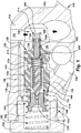
FIG. 1 is a cross section of part of a pump including a pressure relief valve and flow control spool constructed in accordance with the present invention; and -
FIG. 2 a cross section focusing on a poppet valve assembly of the pressure relief valve and flow control spool ofFIG. 1 . - In accordance with the present invention, a pressure relief valve 110 (
FIG. 1 ) includes a poppet valve assembly 112 (FIG. 2 ). Thepressure relief valve 110 is arranged to selectively relieve pressure generated by apump 114. In one example, thepump 114 can pressurize hydraulic fluid for use in a fluid power assist steering system. However, it is contemplated that hydraulic fluid pressurized by thepump 114 may be used in any other desired application. - The
pressure relief valve 110 includes ahousing 116. In one example, thehousing 116 can be integrally formed with thepump 114. However, it is contemplated that thehousing 116 may be formed separately from thepump 114 and subsequently attached. Additionally, it is contemplated that thehousing 116 may be provided remotely from thepump 114 with fluid communication between thehousing 116 and thepump 114 being provided by a suitable connection (e.g., hydraulic lines). - A
cavity 119 is formed in the housing 116.Thecavity 119 includes aseat receiving portion 123 that receives aseat 154. Theseat 154 and thecavity 119 collectively define achamber 122. Therelief valve 110 includes aspool 120 disposed in thechamber 122. Aspring 152 is received in aspring cavity 162 of theseat 154. Thespring 152 is arranged to bias thespool 120 away from theseat 154. - The
spool 120 has a firstaxial end 140 and a secondaxial end 141. Arod portion 128 is provided at the firstaxial end 140 of thespool 120. Therod portion 128 projects from aland 126. Asecond land 130 is located between the firstaxial end 140 and the secondaxial end 141. Agroove 132 is provided between thelands more vent passages 134 extend radially inward from thegroove 132 to acentral cavity 136 formed in thespool 120. - A
poppet seat 138 is screwed into thesecond end 141 of thespool 120. Apoppet 142 is disposed in thecentral cavity 136. Apoppet spring 144 biases thepoppet 142 into engagement with thepoppet seat 138. Anopening 148 is provided in thepoppet seat 138. Fluid flow through theopening 148 is blocked when thepoppet 142 engages thepoppet seat 138. - A
bore 202 is provided in therod portion 128. Aset screw 200 is screwed into thebore 202. Theset screw 200 is coincident with alongitudinal axis 124 of thespool 120. Theset screw 200 has a firstaxial end 206 and an opposite secondaxial end 206. Atool cavity 204 is provided at the firstaxial end 206 of theset screw 200. Aseat engaging portion 208 is provided at the secondaxial end 210 of theset screw 200. Theseat engaging portion 208 engages adisc 212 that is disposed between theset screw 200 and thepoppet spring 144. Ajam screw 214 is screwed into thebore 202. Thejam screw 214 abuts thefirst end 206 of theset screw 200. - The
housing 116 includes anoutlet passage 150 and apressure relief port 156. Theoutlet passage 150 provides a fluid communication path between thepump 114 and the fluid power assist steering system. As will be explained below, thespool 120 is moveable along thelongitudinal axis 124 in thechamber 122 to permit fluid communication between theoutlet passage 150 and thepressure relief port 156 such that an output pressure of thepump 114 is reduced. Thehousing 116 includes aconduit 158 having a flow-restrictingorifice 160. Theconduit 158 provides a fluid communication path between theoutlet passage 150 and thespring cavity 162. - As appreciated by those skilled in the art, a fluid power assist steering system is designed to operate at a maximum pressure level. As will now be explained, the
pressure relief valve 110 is arranged to limit the output pressure of thepump 114 to the maximum pressure level of the fluid power assist steering system. - The
pump 114 is energized to pump fluid through thepassage 150 and provide operating pressure to the fluid power assist steering system. The hydraulic pressure of the fluid flowing through thepassage 150 acts on thespool 120 to urge thespool 120 to the left (as viewed inFIG. 1 ) toward theseat 154 against the force of thespring 152. Theconduit 158 communicates a portion of the fluid flowing through thepassage 150 to thespring cavity 162, thereby generating hydraulic pressure in thespring cavity 162. - The hydraulic pressure in the
spring cavity 162 acts on thepoppet 142 to urge thepoppet 142 to the right (as viewed inFIG. 1 ) away from thepoppet seat 138. However, thepoppet 142 remains engaged with thepoppet seat 138 when the hydraulic pressure of the fluid in thepassage 150 is below the maximum pressure level of the fluid power assist steering system. Thus, the hydraulic pressure in thespring cavity 162 is trapped. The trappedspring cavity 162 hydraulic pressure, in combination with the biasing force of thespring 152, urges thespool 120 to the right (as viewed inFIG. 1 ) against the hydraulic pressure in thepassage 150. However, because the combined force of the hydraulic pressure in thespring cavity 162 and the biasing force of thespring 152 is less than the force of the hydraulic pressure of the fluid flowing through thepassage 150, thespool 120 is maintained in a position where fluid communication between theoutlet passage 150 and thepressure relief port 156 is blocked. That is, thespool 120 is maintained in a position where thefirst land 126 is disposed to the right of the pressure relief port 156 (as viewed inFIG. 1 ). - When the hydraulic pressure of the fluid flowing through the
passage 150 exceeds the maximum pressure level of the fluid power assist steering system, the hydraulic pressure in thespring cavity 162 increases to a pressure that is great enough to move thepoppet 142 off of thepoppet seat 138. Moving thepoppet 142 off of thepoppet seat 138 establishes fluid communication between thespring cavity 162 and thecentral cavity 136. The fluid previously trapped in thespring cavity 162 is thus released through thespool 120 and to thepressure relief port 156 via thevent passages 134. Venting the fluid through thespool 120 and to thepressure relief port 156 reduces the hydraulic pressure in thespring cavity 162. The hydraulic pressure of the fluid flowing through thepassage 150 is now greater than the combined biasing force of thespring 152 and the reduced pressure in thespring cavity 162. As a result, thespool 120 is moved to the left (as viewed inFIG. 1 ) and fluid communication between thepassage 150 and thepressure relief port 156 is permitted. That is, thespool 120 is moved to a position where thefirst land 126 is disposed to the left of thepressure relief port 156. In this position, a portion of fluid flowing through thepassage 150 is diverted to thepressure relief port 156, thereby reducing the output pressure of thepump 114 to the maximum pressure level of the fluid power assist steering system. - The output pressure of the
pump 114 can be adjusted by, among other design variables, varying the biasing force of thepoppet spring 144 on thepoppet 142 into engagement with thepoppet seat 138. This biasing force is increased or decreased by increasing or decreasing, respectively, the compression level of thepoppet spring 144. Increasing the compression level of thepoppet spring 144 will increase the level of hydraulic pressure in thespring cavity 162 that is necessary to move thepoppet 142 off of thepoppet seat 138, thereby increasing the maximum output pressure of thepump 114. Decreasing the compression level of thepoppet spring 144 will decrease the level of hydraulic pressure in thespring cavity 162 that is necessary to move thepoppet 142 off of thepoppet seat 138, thereby decreasing the maximum output pressure of thepump 114. - The compression level of the
poppet spring 144 is controlled by theset screw 200. A tool can be engaged in thetool cavity 204 to facilitate rotation of theset screw 200 about thelongitudinal axis 124. Rotating theset screw 200 about thelongitudinal axis 124 causes theset screw 200 to move along thelongitudinal axis 124 and adjust the compression level of thepoppet spring 144. Specifically, rotating theset screw 200 in a first direction about thelongitudinal axis 124 moves theset screw 200 along thelongitudinal axis 124 toward thepoppet 142 and advances thedisc 212 toward thepoppet 142. The advancingdisk 212 compresses thepoppet spring 144, thereby increasing the compression level of thepoppet spring 144. Rotating theset screw 200 in a second direction about thelongitudinal axis 124 opposite the first direction moves theset screw 200 along thelongitudinal axis 124 away from thepoppet 142. Thedisk 212 retreats away from thepoppet 142 under the force of thepoppet spring 144, thereby decreasing the compression level of thepoppet spring 144. Once theset screw 200 is located at a position in thebore 202 that provides the desired maximum output pressure, thejam screw 214 can be screwed into abutment with thefirst end 206 of theset screw 200, thereby fixing the location of theset screw 200 in thebore 202. It is contemplated that thejam screw 214 can be omitted and, instead, threadlocker (e.g., nylon or other suitable material) can be bonded to theset screw 200 threads to fix the location of theset screw 200 in thebore 202. - The
set screw 200 can be moved in thebore 202 to an infinite number of locations along thelongitudinal axis 124. Consequently, the compression level of thepoppet spring 144 can be infinitely adjusted, thereby allowing for precise setting of the maximum output pressure of thepump 114. Furthermore, the compression level of thepoppet spring 144 can be adjusted without complete disassembly of therelief valve 110. Additionally, because the movement of theset screw 200 along thelongitudinal axis 124 relative to thespool 120 in thebore 202 is a direct function of the amount of rotation of theset screw 200, theset screw 200 can be moved in the bore 202 a predetermined distance by rotating the set screw 200 a predetermined angle. Thus, the compression of thepoppet spring 144 can be accurately adjusted by tracking rotation of theset screw 200. - From the above description of the invention, those skilled in the art will perceive improvements, changes and modifications. Such improvements, changes and modifications within the skill of the art are intended to be covered by the appended claims.
Claims (13)
- A pressure relief valve for a fluid power assist steering system pump comprising:a housing;a spool disposed in the housing, the spool defining a cavity and having a first end and a second end, the spool being movable in the housing to limit an output pressure of the pump;a poppet seat secured to the second end of the spool;a poppet disposed in the cavity;a poppet spring biasing the poppet into engagement with the poppet seat; anda set screw received in the first end of the spool, the set screw being rotatable relative to the spool to adjust a compression level of the poppet spring.
- The pressure relief valve of claim 1, wherein the compression level of the poppet spring corresponds to the output pressure limit of the pump.
- The pressure relief valve of claim 2, wherein increasing the compression level of the poppet spring increases the output pressure limit of the pump and decreasing the compression level of the poppet spring decreases the output pressure limit of the pump.
- The pressure relief valve of any of the preceding claims comprising a jam screw received in the first end of the spool, the jam screw abutting the set screw.
- The pressure relief valve of any of the preceding claims comprising threadlocker applied to threads of the set screw.
- The pressure relief of any of the preceding claims comprising a disc disposed between the poppet spring and the set screw.
- The pressure relief valve of any of the preceding claims, wherein the set screw includes a tool cavity for receiving a tool that can be used to rotate the set screw relative to the spool.
- The pressure relief valve of any of the preceding claims, wherein rotation of the set screw relative to the spool causes axial movement of the set screw relative to the spool.
- The pressure relief valve of any of the preceding claims comprising:a spring; andwherein the housing has an outlet passage and a pressure relief port, the outlet passage providing a fluid communication path between the pump and the fluid power assist steering system, the pressure relief port being arranged to reduce the output pressure of the pump, the spring biasing the spool to a position where fluid communication between the outlet passage and the pressure relief port is blocked.
- The pressure relief valve of claim 9, wherein the spool is movable by pressure in the outlet passage against the bias of the spring to a position where fluid communication between the outlet passage and the pressure relief port is permitted.
- The pressure relief valve of claim 10, wherein the poppet is arranged to be moved by hydraulic pressure generated by the fluid flowing through the outlet passage to block fluid from flowing through the poppet seat or allow fluid to flow through the poppet seat and into the cavity.
- The pressure relief valve of claim 11, wherein the spool includes a vent passage that allows fluid to flow from the cavity to the pressure relief port.
- The pressure relief valve of claim 12, wherein the spool moves to a position that permits fluid communication between the outlet passage when the poppet is moved to permit fluid to flow through the poppet seat into the cavity and to the pressure relief port.
Applications Claiming Priority (1)
| Application Number | Priority Date | Filing Date | Title |
|---|---|---|---|
| US15/831,458 US10465811B2 (en) | 2017-12-05 | 2017-12-05 | Pressure relief valve |
Publications (1)
| Publication Number | Publication Date |
|---|---|
| EP3495704A1 true EP3495704A1 (en) | 2019-06-12 |
Family
ID=64500278
Family Applications (1)
| Application Number | Title | Priority Date | Filing Date |
|---|---|---|---|
| EP18208617.3A Withdrawn EP3495704A1 (en) | 2017-12-05 | 2018-11-27 | Pressure relief valve |
Country Status (2)
| Country | Link |
|---|---|
| US (1) | US10465811B2 (en) |
| EP (1) | EP3495704A1 (en) |
Cited By (1)
| Publication number | Priority date | Publication date | Assignee | Title |
|---|---|---|---|---|
| CN110294017A (en) * | 2019-07-03 | 2019-10-01 | 四川航庆机械制造有限公司 | A kind of new type auto stroke off-load valve assembly |
Citations (6)
| Publication number | Priority date | Publication date | Assignee | Title |
|---|---|---|---|---|
| US2587161A (en) * | 1945-09-17 | 1952-02-26 | New York Air Brake Co | Pressure relief valve |
| US3583157A (en) * | 1969-10-06 | 1971-06-08 | Abex Corp | Hydrostatic transmission |
| GB2012025A (en) * | 1978-01-05 | 1979-07-18 | Zahnradfabrik Friedrichshafen | Adjustable pressure-responsive valve |
| JPH01133077U (en) * | 1988-02-29 | 1989-09-11 | ||
| US5460198A (en) * | 1993-05-28 | 1995-10-24 | Luk Fahrzeug-Hydraulik Gmbh & Co. Kg | Pressure-activated flow-control valve |
| US20040244838A1 (en) * | 2003-06-06 | 2004-12-09 | Trw Automotive U.S. Llc | Valve assembly |
Family Cites Families (4)
| Publication number | Priority date | Publication date | Assignee | Title |
|---|---|---|---|---|
| US4982762A (en) * | 1989-03-15 | 1991-01-08 | Deere & Company | Hydraulic lift with weight transfer |
| US5603348A (en) * | 1995-05-01 | 1997-02-18 | Sauer Inc. | Damped poppet valve |
| US7063100B2 (en) * | 2003-03-06 | 2006-06-20 | Hydraforce Inc. | Flow regulator with pressure relief combination valve |
| BRPI0819901A2 (en) * | 2007-11-26 | 2015-05-19 | Cameron Int Corp | Self-sealing Chemical Injection Line Coupling |
-
2017
- 2017-12-05 US US15/831,458 patent/US10465811B2/en active Active
-
2018
- 2018-11-27 EP EP18208617.3A patent/EP3495704A1/en not_active Withdrawn
Patent Citations (6)
| Publication number | Priority date | Publication date | Assignee | Title |
|---|---|---|---|---|
| US2587161A (en) * | 1945-09-17 | 1952-02-26 | New York Air Brake Co | Pressure relief valve |
| US3583157A (en) * | 1969-10-06 | 1971-06-08 | Abex Corp | Hydrostatic transmission |
| GB2012025A (en) * | 1978-01-05 | 1979-07-18 | Zahnradfabrik Friedrichshafen | Adjustable pressure-responsive valve |
| JPH01133077U (en) * | 1988-02-29 | 1989-09-11 | ||
| US5460198A (en) * | 1993-05-28 | 1995-10-24 | Luk Fahrzeug-Hydraulik Gmbh & Co. Kg | Pressure-activated flow-control valve |
| US20040244838A1 (en) * | 2003-06-06 | 2004-12-09 | Trw Automotive U.S. Llc | Valve assembly |
Cited By (2)
| Publication number | Priority date | Publication date | Assignee | Title |
|---|---|---|---|---|
| CN110294017A (en) * | 2019-07-03 | 2019-10-01 | 四川航庆机械制造有限公司 | A kind of new type auto stroke off-load valve assembly |
| CN110294017B (en) * | 2019-07-03 | 2021-04-23 | 四川航庆机械制造有限公司 | Novel automatic stroke unloading valve assembly |
Also Published As
| Publication number | Publication date |
|---|---|
| US20190170265A1 (en) | 2019-06-06 |
| US10465811B2 (en) | 2019-11-05 |
Similar Documents
| Publication | Publication Date | Title |
|---|---|---|
| RU2133889C1 (en) | Driving stage for safety valve, indirect-acting manually-regulated safety valve and indirect-acting proportional safety valve | |
| EP1701074B1 (en) | Soft ventable relief valve | |
| US5366202A (en) | Displacement controlled hydraulic proportional valve | |
| US7921878B2 (en) | Control valve with load sense signal conditioning | |
| US5567123A (en) | Pump displacement control for a variable displacement pump | |
| US10323762B2 (en) | Three-way pressure control and flow regulator valve | |
| US5611199A (en) | Two stage electrohydraulic pressure control valve | |
| US20020011269A1 (en) | Pressure-control valve | |
| US10465811B2 (en) | Pressure relief valve | |
| US6848475B2 (en) | Electro-hydraulic valve and system | |
| EP2585888A1 (en) | Infinitely variable pressure-control valve | |
| KR20030017324A (en) | Relief valve and hydraulic device having the relief valve | |
| US9297369B2 (en) | Hydrostatic machine having a control device having a return element for controlling a regulating valve | |
| EP0112267B1 (en) | Servo control variable displacement pressure compensated pump | |
| US7017605B2 (en) | Valve assembly | |
| US3785398A (en) | Power transmission | |
| CA2073592C (en) | Power limiter control for variable displacement axial piston pump | |
| EP0724076B1 (en) | Control for a variable displacement axial piston pump | |
| DE19953170A1 (en) | Power control device for hydraulic pump has control valve acted upon by final control element with variable additional force | |
| KR101740925B1 (en) | Hydraulic assembly comprising a variable displacement pump and a relief valve | |
| DE10062428A1 (en) | Servo-assisted pressure feed valve has flow regulating valve in control oil flow path to transfer cavity | |
| DE3143074C2 (en) | ||
| CN213655278U (en) | Control device and work apparatus | |
| US4106818A (en) | Braking system for vehicle | |
| WO2023150448A1 (en) | Pressure relief valve with a reverse free flow configuration integrated therewith |
Legal Events
| Date | Code | Title | Description |
|---|---|---|---|
| PUAI | Public reference made under article 153(3) epc to a published international application that has entered the european phase |
Free format text: ORIGINAL CODE: 0009012 |
|
| AK | Designated contracting states |
Kind code of ref document: A1 Designated state(s): AL AT BE BG CH CY CZ DE DK EE ES FI FR GB GR HR HU IE IS IT LI LT LU LV MC MK MT NL NO PL PT RO RS SE SI SK SM TR |
|
| AX | Request for extension of the european patent |
Extension state: BA ME |
|
| 17P | Request for examination filed |
Effective date: 20191122 |
|
| RBV | Designated contracting states (corrected) |
Designated state(s): AL AT BE BG CH CY CZ DE DK EE ES FI FR GB GR HR HU IE IS IT LI LT LU LV MC MK MT NL NO PL PT RO RS SE SI SK SM TR |
|
| 17Q | First examination report despatched |
Effective date: 20200304 |
|
| RAP1 | Party data changed (applicant data changed or rights of an application transferred) |
Owner name: ZF ACTIVE SAFETY AND ELECTRONICS US LLC |
|
| STAA | Information on the status of an ep patent application or granted ep patent |
Free format text: STATUS: THE APPLICATION IS DEEMED TO BE WITHDRAWN |
|
| 18D | Application deemed to be withdrawn |
Effective date: 20201124 |