EP3495690A1 - Conveying device - Google Patents
Conveying device Download PDFInfo
- Publication number
- EP3495690A1 EP3495690A1 EP16911609.2A EP16911609A EP3495690A1 EP 3495690 A1 EP3495690 A1 EP 3495690A1 EP 16911609 A EP16911609 A EP 16911609A EP 3495690 A1 EP3495690 A1 EP 3495690A1
- Authority
- EP
- European Patent Office
- Prior art keywords
- rod
- coupler
- couplers
- shaped member
- shaped
- Prior art date
- Legal status (The legal status is an assumption and is not a legal conclusion. Google has not performed a legal analysis and makes no representation as to the accuracy of the status listed.)
- Granted
Links
Images







Classifications
-
- F—MECHANICAL ENGINEERING; LIGHTING; HEATING; WEAPONS; BLASTING
- F16—ENGINEERING ELEMENTS AND UNITS; GENERAL MEASURES FOR PRODUCING AND MAINTAINING EFFECTIVE FUNCTIONING OF MACHINES OR INSTALLATIONS; THERMAL INSULATION IN GENERAL
- F16D—COUPLINGS FOR TRANSMITTING ROTATION; CLUTCHES; BRAKES
- F16D1/00—Couplings for rigidly connecting two coaxial shafts or other movable machine elements
- F16D1/10—Quick-acting couplings in which the parts are connected by simply bringing them together axially
-
- F—MECHANICAL ENGINEERING; LIGHTING; HEATING; WEAPONS; BLASTING
- F16—ENGINEERING ELEMENTS AND UNITS; GENERAL MEASURES FOR PRODUCING AND MAINTAINING EFFECTIVE FUNCTIONING OF MACHINES OR INSTALLATIONS; THERMAL INSULATION IN GENERAL
- F16D—COUPLINGS FOR TRANSMITTING ROTATION; CLUTCHES; BRAKES
- F16D41/00—Freewheels or freewheel clutches
- F16D41/06—Freewheels or freewheel clutches with intermediate wedging coupling members between an inner and an outer surface
- F16D41/061—Freewheels or freewheel clutches with intermediate wedging coupling members between an inner and an outer surface the intermediate members wedging by movement having an axial component
-
- F—MECHANICAL ENGINEERING; LIGHTING; HEATING; WEAPONS; BLASTING
- F16—ENGINEERING ELEMENTS AND UNITS; GENERAL MEASURES FOR PRODUCING AND MAINTAINING EFFECTIVE FUNCTIONING OF MACHINES OR INSTALLATIONS; THERMAL INSULATION IN GENERAL
- F16H—GEARING
- F16H25/00—Gearings comprising primarily only cams, cam-followers and screw-and-nut mechanisms
- F16H25/18—Gearings comprising primarily only cams, cam-followers and screw-and-nut mechanisms for conveying or interconverting oscillating or reciprocating motions
- F16H25/20—Screw mechanisms
-
- F—MECHANICAL ENGINEERING; LIGHTING; HEATING; WEAPONS; BLASTING
- F16—ENGINEERING ELEMENTS AND UNITS; GENERAL MEASURES FOR PRODUCING AND MAINTAINING EFFECTIVE FUNCTIONING OF MACHINES OR INSTALLATIONS; THERMAL INSULATION IN GENERAL
- F16H—GEARING
- F16H25/00—Gearings comprising primarily only cams, cam-followers and screw-and-nut mechanisms
- F16H25/18—Gearings comprising primarily only cams, cam-followers and screw-and-nut mechanisms for conveying or interconverting oscillating or reciprocating motions
- F16H25/20—Screw mechanisms
- F16H25/24—Elements essential to such mechanisms, e.g. screws, nuts
-
- F—MECHANICAL ENGINEERING; LIGHTING; HEATING; WEAPONS; BLASTING
- F16—ENGINEERING ELEMENTS AND UNITS; GENERAL MEASURES FOR PRODUCING AND MAINTAINING EFFECTIVE FUNCTIONING OF MACHINES OR INSTALLATIONS; THERMAL INSULATION IN GENERAL
- F16H—GEARING
- F16H49/00—Other gearings
-
- H—ELECTRICITY
- H02—GENERATION; CONVERSION OR DISTRIBUTION OF ELECTRIC POWER
- H02K—DYNAMO-ELECTRIC MACHINES
- H02K7/00—Arrangements for handling mechanical energy structurally associated with dynamo-electric machines, e.g. structural association with mechanical driving motors or auxiliary dynamo-electric machines
- H02K7/06—Means for converting reciprocating motion into rotary motion or vice versa
-
- F—MECHANICAL ENGINEERING; LIGHTING; HEATING; WEAPONS; BLASTING
- F16—ENGINEERING ELEMENTS AND UNITS; GENERAL MEASURES FOR PRODUCING AND MAINTAINING EFFECTIVE FUNCTIONING OF MACHINES OR INSTALLATIONS; THERMAL INSULATION IN GENERAL
- F16D—COUPLINGS FOR TRANSMITTING ROTATION; CLUTCHES; BRAKES
- F16D1/00—Couplings for rigidly connecting two coaxial shafts or other movable machine elements
- F16D1/10—Quick-acting couplings in which the parts are connected by simply bringing them together axially
- F16D2001/103—Quick-acting couplings in which the parts are connected by simply bringing them together axially the torque is transmitted via splined connections
Definitions
- the present invention relates to a transfer technique, more particularly to a transfer apparatus.
- a male magnetic screw made of a magnetic material is rotated to move a female magnetic screw such as a nut made of a magnetic material in a direction of a central axis of the male magnetic screw.
- a transfer member on which an article to be transferred is disposed is fixed to the female magnetic screw. The transfer member also moves in the direction of the central axis of the male magnetic screw together with the movement of the female magnetic screw.
- the male magnetic screw may be divided into a plurality of male magnetic screws and then they may be disposed.
- the female magnetic screw moves across the plurality of male magnetic screws.
- the female magnetic screw cannot move across the gaps between the male magnetic screws smoothly unless the interval between adjacent male magnetic screws is set appropriately.
- PTL 1 proposes that the interval between the male magnetic screws is set to a multiple of the double of the pitch of the magnetized patterns of the male magnetic screws.
- adjacent male magnetic screws are disposed at predetermined intervals and the adjacent male magnetic screws are not coupled to or separated from each other.
- adjacent male magnetic screws are preferably coupled to or separated from each other in some cases. Therefore, one object of the invention is to provide a transfer apparatus in which rod-shaped members such as male magnetic screws can be coupled to or separated from each other.
- a transfer apparatus including (a) a first rod-shaped member that includes a magnetic material, the first rod-shaped member being provided with a spiral pattern, (b) a first coupler that is fixed to an end portion of the first rod-shaped member, (c) a second rod-shaped member that includes a magnetic material, the second rod-shaped member being provided with a spiral pattern, (d) a second coupler that is fixed to an end portion of the second rod-shaped member, the second coupler being coupled to the first coupler so as to make a relative angle between the spiral pattern of the first rod-shaped member and the spiral pattern of the second rod-shaped member constant when coupled to each other, (e) an opposite member that is opposed to parts of side surfaces of the first and second rod-shaped members, the opposite member including a magnetic material, and (f) a driving device configured to rotate the first and second rod-shaped members about central axes of the first and second rod-shaped members and move the opposite member along the first and second rod-shaped members.
- the first and second couplers may be coupled to each other by bringing the first and second rod-shaped members close to each other while rotating at least one of the first and second rod-shaped members.
- the first and second couplers may have spiral structures that engage with each other.
- a spiral curved surface of the spiral structure of one of the first and second couplers of the transfer apparatus described above may be provided with a projection portion and a spiral curved surface of the spiral structure of the other of the first and second couplers may be provided with a concave portion into which the projection portion is inserted.
- the first and second couplers may have first flat surfaces that are parallel with directions of the central axes of the first and second rod-shaped members and oriented to a first rotational direction of the first and second rod-shaped members and second flat surfaces that are parallel with the directions of the central axes of the first and second rod-shaped members and oriented to a second rotational direction of the first and second rod-shaped members.
- the first and second couplers may have engagement structures that engage with each other and at least one of the first and second couplers may have an elastic member that contracts when the first and second couplers come into contact with each other and the first and second couplers do not engage with each other.
- the first and second couplers may have engagement structures that engage with each other and the engagement structures may change a relative angle between the first and second couplers using at least one of an attraction force between different magnetic poles and a repulsion force between identical magnetic poles.
- Each of the first and second couplers may have a convex surface having a first magnetic pole and a concave surface having a second magnetic pole.
- the first and second rod-shaped members and the opposite member may include hard magnetic materials and, when the number of poles in a combination of the first or second rod-shaped member and the opposite member is 2n (where n represents a natural number), the first and second couplers may be configured to be couplable to each other every relative rotation by 360 ⁇ m/n degrees (where m represents a natural number).
- one of the first and second rod-shaped members and the opposite member may include a hard magnetic material and the other may include a soft magnetic material and, when the number of poles in a combination between the first or second rod-shaped member and the opposite member is 2n (where n represents a natural number), the first and second couplers may be configured to be couplable to each other every relative rotation by 180 ⁇ m/n degrees (where m represents a natural number).
- the first rod-shaped member may be disposed in a furnace.
- the furnace may be a temperature-controlled furnace having a temperature-controlled space.
- the temperature-controlled furnace may be a freeze drying furnace.
- the furnace may be a cleaning furnace having a cleanliness-controlled space.
- the furnace may be a vacuum furnace having a vacuum-evacuated space.
- the transfer apparatus described above may further include a transfer member for transferring an article, which is fixed to the opposite member.
- the opposite member when the driving device rotates the first and second rod-shaped members, the opposite member may move along the central axes of the first and second rod-shaped members and the transfer member fixed to the opposite member may move.
- the article may include a medicine.
- the first and second couplers may be coupled to each other when the furnace is opened and the first and second couplers may be separated from each other when the furnace is closed.
- the transfer apparatus described above may further include a base member, a table positioned on the base member, a table movement rod-shaped member that includes a magnetic material, a table movement opposite member that is opposed to a part of a side surface of the table movement rod-shaped member and includes a magnetic material, and a table driving device that rotates the table movement rod-shaped member or the table movement opposite member about a central axis of the table movement rod-shaped member, changes a relative position between the table movement rod-shaped member and the table movement opposite member, and moves the table and the second rod-shaped member may be disposed on the table.
- the table movement opposite member when the table driving device rotates the table movement rod-shaped member, the table movement opposite member may move along the central axis of the table movement rod-shaped member and the table fixed to the table movement opposite member and the second rod-shaped member disposed on the table may move.
- the table movement rod-shaped member when the table driving device rotates the table movement opposite member, the table movement rod-shaped member may move in a direction of the central axis and the table fixed to the table movement rod-shaped member and the second rod-shaped member disposed on the table may move.
- the table may come close to the furnace to couple the first and second couplers to each other or the table may be separated from the furnace to separate the first and second couplers from each other.
- the transfer apparatus described above may further include a wheel provided in the base member.
- rod-shaped members such as male magnetic screws can be coupled to or separated from each other.
- a transfer apparatus includes first rod-shaped members 2A and 2B, including magnetic materials, that are provided with spiral patterns, first couplers 42A and 42B that are fixed to end portions of the first rod-shaped members 2A and 2B, second rod-shaped members 12A and 12B, including magnetic materials, that are provided with spiral patterns, and second couplers 52A and 52B, fixed to end portions of the second rod-shaped members 12A and 12B, that are coupled to the first couplers 42A and 42B so as to make relative angles between the spiral patterns of the first rod-shaped members 2A and 2B and the spiral patterns of the second rod-shaped members 12A and 12B constant.
- the transfer apparatus further includes an opposite member 3A, opposed to parts of side surfaces of the first and second rod-shaped members 2A and 12A, that includes a magnetic material, an opposite member 3B, opposed to parts of side surfaces of the first and second rod-shaped members 2B and 12B, that includes a magnetic material, a driving device that rotates the first and second rod-shaped members 2A and 12A about central axes of the first and second rod-shaped members 2A and 12A, moves the opposite member 3A along the first and second rod-shaped members 2A and 12A, rotates the first and second rod-shaped members 2B and 12B about central axes of the first and second rod-shaped members 2B and 12B, and moves the opposite member 3B along the first and second rod-shaped members 2B and 12B, and a transfer member 6 that moves together with the opposite members 3A and 3B and transfers an article 5.
- an opposite member 3A opposed to parts of side surfaces of the first and second rod-shaped members 2A and 12A, that includes a magnetic material
- the first rod-shaped members 2A and 2B are disposed in, for example, a temperature-controlled furnace 1 in which the article 5 is disposed and that has a temperature-controlled space.
- the temperature-controlled furnace 1 is, for example, a freeze drying furnace.
- a shelf board 7 is disposed in the temperature-controlled furnace 1 and the article 5 including an object to be freeze-dried is disposed on the shelf board 7.
- the article 5 is, for example, a vial into which a medicine has been poured.
- the cylindrical first rod-shaped member 2A is rotatably held in the temperature-controlled furnace 1 by a bearing.
- the first rod-shaped member 2A is a magnetic screw including a hard magnetic material and a spiral pattern of S pole magnetized zones and a spiral pattern of N pole magnetized zones are alternately provided on an outer peripheral surface thereof.
- the first rod-shaped member 2A may be inserted into a thin-walled pipe 20A made of a nonmagnetic material.
- the pipe 20A is made of, for example, stainless steel.
- the first rod-shaped member 2A and the pipe 20A are integrated with each other and, when the first rod-shaped member 2A rotates, the pipe 20A also rotates about the central axis of the first rod-shaped member 2A.
- the cylindrical first rod-shaped member 2B illustrated in Fig. 1 is also rotatably held in parallel with the first rod-shaped member 2A by a bearing in the temperature-controlled furnace 1.
- the structure of the first rod-shaped member 2B is the same as that of the first rod-shaped member 2A.
- the cylindrical second rod-shaped members 12A and 12B are rotatably held by, for example, bearings or the like disposed on a table 22 illustrated in Fig. 2 .
- the structures of the second rod-shaped members 12A and 12B are the same as that of the first rod-shaped member 2A illustrated in Fig. 3 .
- the first coupler 42A is fixed to the end portion of the first rod-shaped member 2A and the second coupler 52A is fixed to the end portion of the second rod-shaped member 12A.
- the first coupler 42A and the second coupler 52A can be coupled to or separated from each other. Accordingly, the first rod-shaped member 2A and the second rod-shaped member 12A can be separated from or coupled serially to each other via the first and second couplers 42A and 52A.
- the first and second rod-shaped members 2A and 12A coupled to each other are rotated synchronously by a rotating force applied to at least one of them.
- first coupler 42B is fixed to the end portion of the first rod-shaped member 2B and the second coupler 52B is fixed to the end portion of the second rod-shaped member 12B.
- the first coupler 42B and the second coupler 52B can be coupled to or separated from each other. Accordingly, the first rod-shaped member 2B and the second rod-shaped member 12B can be separated from or coupled serially to each other via the first and second couplers 42B and 52B.
- the first and second rod-shaped members 2B and 12B coupled to each other are rotated synchronously by a rotating force applied to at least one of them.
- the opposite member 3A is a magnetic nut including a hard magnetic material and provided with a hole having an inner circumference larger than outer circumferences of the first and second rod-shaped members 2A and 12A.
- the first and second rod-shaped members 2A and 12A penetrate through the hole in the opposite member 3A having a nut shape.
- a spiral pattern of S pole magnetized zones and a spiral pattern of N pole magnetized zones are alternately provided on an inner peripheral surface of the hole in the opposite member 3A.
- the pitch of the magnetized zones of the opposite member 3A is substantially the same as the pitch of the magnetized zones of the first and second rod-shaped members 2A and 12A.
- Guide rings 31 and 32 such as bushes may be provided on an inner peripheral surface of the opposite member 3A.
- the inner circumferences of the guide rings 31 and 32 are smaller than the inner circumference of the opposite member 3A and make contact with the outer peripheral surface of the pipe 20A. Therefore, a constant interval is kept between the magnetized zones of the first and second rod-shaped members 2A and 12A and the magnetized zones of the opposite member 3A.
- the guide rings 31 and 32 are made of materials having a small friction coefficient, such as fluororesin.
- the structure of the opposite member 3B illustrated in Fig. 1 is the same as that of the opposite member 3A.
- the first and second rod-shaped members 2B and 12B penetrate through a hole in the opposite member 3B having a nut shape.
- the transfer member 6 is fixed between the opposite member 3A and the opposite member 3B.
- the article 5 to be moved between the table 22 and the temperature-controlled furnace 1 is disposed in the transfer member 6.
- the transfer member 6 may make contact with the article 5 and push the article 5 to be transferred.
- a driving device 14A illustrated in Fig. 5 includes, for example, a rotating motor.
- the driving device 14A is fixed to the table 22.
- the driving device 14A is connected to a controlling device.
- the driving device 14A may be covered with a shield or the like that prevents diffusion of dust that may be generated or the like.
- the driving device 14A and the second rod-shaped member 12A are connected to each other via, for example, a belt drive.
- the driving device 14A and the belt drive are covered with, for example, a shield 144A for prevention of dust.
- a sealing member such as an oil seal is provided in a hole of the shield 144A through which a mandrel connecting a pulley of the belt drive and the second rod-shaped member 12A penetrates.
- the driving device 14A rotates the second rod-shaped member 12A about the central axis and changes the relative position between the second rod-shaped member 12A and the opposite member 3A.
- a driving device (not illustrated) rotates the second rod-shaped member 12B illustrated in Fig. 1 and Fig. 4 about the central axis and changes the relative position between the second rod-shaped member 12B and the opposite member 3B.
- the driving device 14A illustrated in Fig. 5 and the driving device that drives the second rod-shaped member 12B illustrated in Fig. 1 synchronously rotate the second rod-shaped members 12A and 12B.
- the second rod-shaped members 12A and 12B are rotated, the first rod-shaped members 2A and 2B coupled thereto are also rotated.
- the driving device rotates the first and second rod-shaped members 2B and 12B
- a magnetic force acts between the magnetized zones of the first or second rod-shaped member 2B or 12B and the magnetized zones of the opposite member 3B.
- the opposite member 3B is fixed to the transfer member 6 and the opposite member 3A and cannot rotate. Therefore, when the first and second rod-shaped members 2B and 12B rotate, the opposite member 3B moves along the central axes of the first and second rod-shaped members 2B and 12B.
- the transfer member 6 fixed to the opposite members 3A and 3B also moves along the central axes of the first and second rod-shaped members 2A, 2B, 12A, and 12B and moves from the table 22 onto the shelf board 7 or from the shelf board 7 onto the table 22 depending on the rotational directions of the first and second rod-shaped members 2A, 2B, 12A, and 12B. This moves the article 5 from the table 22 onto the shelf board 7 or from the shelf board 7 onto the table 22.
- the transfer apparatus further includes a base member 121 positioned below the table 22, a table movement rod-shaped member 102A at least a pat of which is disposed on the base member 121 and that includes a magnetic material, a table movement opposite member 103A that is opposed to a part of a side surface of the table movement rod-shaped member 102A and includes a magnetic material, and a table driving device 104A that rotates the table movement rod-shaped member 102A about a central axis and changes the relative position between the table movement rod-shaped member 102A and the table movement opposite member 103A.
- the table movement rod-shaped member 102A is held by, for example, a bearing or the like disposed on the base member 121.
- the table driving device 104A is fixed onto the base member 121 and covered with, for example, a shield 134A for prevention of dust.
- the table driving device 104A and the table movement rod-shaped member 102A are connected to each other via, for example, a mandrel.
- a hole of the shield 134A through which the mandrel penetrates is provided with a sealing member such as, for example, an oil seal.
- a table movement rail 125A is disposed in parallel with the central axis of the table movement rod-shaped member 102A.
- a driver transmission member 128 is disposed on the base member 121 via guides 126A and 126B that are slidable along the table movement rail 125A.
- the drive transmission member 128 is fixed to the table movement opposite member 103A and the table 22.
- the table movement opposite member 103A moves along the central axis of the table movement rod-shaped member 102A by a magnetic force.
- the drive transmission member 128 fixed to the table movement opposite member 103A moves along the central axis of the table movement rod-shaped member 102A.
- the table 22 fixed to the drive transmission member 128 moves along the central axis of the table movement rod-shaped member 102A.
- a table driving device On the base member 121, another set of a table driving device, a table movement rod-shaped member, and a table movement opposite member may be disposed in parallel with the table driving device 104A, the table movement rod-shaped member 102A, and the table movement opposite member 103A.
- the table 22 is moved in the direction toward the temperature-controlled furnace 1 to bring the table 22 close to the temperature-controlled furnace 1.
- the table 22 and the temperature-controlled furnace 1 may be couplable to each other. This brings the second rod-shaped members 12A and 12B disposed on the table 22 close to the first rod-shaped members 2A and 2B disposed in the temperature-controlled furnace 1.
- the first couplers 42A and 42B and the second couplers 52A and 52B are coupled to each other. This enables the article 5 to move from the table 22 onto the shelf board 7 or from the shelf board 7 onto the table 22 when the temperature-controlled furnace 1 is opened.
- the table 22 is moved in the direction opposite to the temperature-controlled furnace 1 to move the table 22 away from the temperature-controlled furnace 1. This moves the second rod-shaped members 12A and 12B disposed on the table 22 away from the first rod-shaped members 2A and 2B disposed in the temperature-controlled furnace 1.
- the first couplers 42A and 42B are separated from the second couplers 52A and 52B, respectively. This enables the door of the temperature-controlled furnace 1 to be closed.
- wheels 123A and 123B illustrated in Fig. 5 may be provided on a bottom surface side of the base member 121.
- the wheels 123A and 123B may rotate on floor rails 124A and 124B, respectively, that extend in an orthogonal direction with respect to the central axis of the table movement rod-shaped member 102A.
- the table 22 can be moved in the orthogonal direction with respect to the central axis of the table movement rod-shaped member 102A via the wheels 123A and 123B.
- the first and second couplers 42A and 52A have, for example, spiral structures 142A and 152A that engage with each other.
- the spiral structures 142A and 152A are wound around the central axes of the first and second rod-shaped members 2A and 12A.
- the spiral structure 142A of the first coupler 42A has a spiral curved surface 242A.
- the spiral curved surface 242A has, for example, a spiral shape formed along the cylindrical surface and the spiral structure 142A may have, for example, one set of spiral curved surfaces 242A that are 2-fold symmetric. Each of the one set of spiral curved surfaces 242A is wound by a half turn.
- the first coupler 42A further includes a flat surface 342A that is parallel with the central axis of the first rod-shaped member 2A.
- the flat surface 342A is orthogonal to the rotational direction of the first coupler 42A. For example, the end portion of the spiral curved surface 242A makes contact with the flat surface 342A.
- the spiral structure 152A of the second coupler 52A has a spiral curved surface 252A.
- the spiral curved surface 252A has, for example, a spiral shape formed along the cylindrical surface and the spiral structure 152A may have, for example, one set of spiral curved surfaces 252A that are 2-fold symmetric. Each of the one set of spiral curved surfaces 252A is wound by a half turn.
- the second coupler 52A further includes a flat surface 352A that is parallel with the central axis of the second rod-shaped member 12A.
- the flat surface 352A is orthogonal to the rotational direction of the second coupler 52A. For example, the end portion of the spiral curved surface 252A makes contact with the flat surface 352A.
- the second coupler 52A is brought close to the first coupler 42A by moving the second coupler 52A in the direction of the central axis of the second rod-shaped member 12A while rotating the second coupler 52A.
- the second coupler 52A is rotated in a direction in which the flat surface 352A of the second coupler 52A comes close to the flat surface 342A of the first coupler 42A.
- the approach speed and the rotational speed of the second coupler 52A are controlled so that the angle formed by the flat surface orthogonal to the central axis of the second coupler 52A and the spiral line drawn by the track of the end portion of the spiral curved surface 252A when the second coupler 52A comes close while rotating is smaller than the angle formed by the flat surface orthogonal to the central axis of the first coupler 42A and the spiral line of the spiral curved surface 242A.
- the spiral curved surface 252A of the second coupler 52A makes contact with the spiral curved surface 242A of the first coupler 42A, the spiral structure 142A engages with the spiral structure 152A, and the second coupler 52A and the first coupler 42A are coupled to each other as illustrated in Fig. 10 .
- the relative angle becomes a predetermined angle when they are coupled to each other.
- the relative angle between the first and second couplers 42A and 52A when they are coupled to each other and the total length of the first and second couplers 42A and 52A in the direction of the central axis when they are coupled to each other are set so that the phase of the spiral pattern of the first rod-shaped member 2A coincides with the phase of the spiral pattern of the second rod-shaped member 12A and the spiral pattern of the second rod-shaped member 12A is present on an extension of the spiral pattern of the first rod-shaped member 2A.
- the opposite member 3A can move smoothly from the first rod-shaped member 2A to the second rod-shaped member 12A or from the second rod-shaped member 12A to the first rod-shaped member 2A by straddling the first and second couplers 42A and 52A. This is true of other embodiments that will be described later.
- the second coupler 52A is moved away from the first coupler 42A without rotating the second coupler 52A.
- the second coupler 52A is moved away from the first coupler 42A while rotating the second coupler 52A in a direction in which the flat surface 352A of the second coupler 52A is separated from the flat surface 342A of the first coupler 42A.
- the first and second couplers 42B and 52B illustrated in Fig. 1 are also coupled to or separated from each other as in the first and second couplers 42A and 52A.
- a driving force is transmitted between the first and second rod-shaped members 2A and 12A and the opposite member 3A and between the first and second rod-shaped members 2B and 12B and the opposite member 3B in a non-contact manner by a magnetic force. Accordingly, when a driving force is transmitted between the rod-shaped members and the opposite member, heat and dust are unlikely to be generated. Therefore, even when the first rod-shaped members 2A and 2B and the opposite members 3A and 3B are disposed in the temperature-controlled space of the temperature-controlled furnace 1, an influence of heat generation in the temperature-controlled space can be suppressed and the temperature-controlled space can be kept clean.
- the first rod-shaped members 2A and 2B are rotated via the second rod-shaped members 12A and 12B and the driving device that drives the second rod-shaped members 12A and 12B is disposed outside the temperature-controlled space of the temperature-controlled furnace 1. Therefore, even if dust is generated in the driving device, the dust is unlikely to enter the temperature-controlled space of the temperature-controlled furnace 1.
- the driving device is disposed inside the temperature-controlled furnace, a temperature distribution may become uneven inside the temperature-controlled furnace such as a freeze drying furnace due to the heated driving device. In this case, the quality of a plurality of articles disposed in the temperature-controlled furnace may become uneven.
- the transfer apparatus according to the first embodiment since the driving device is disposed outside the temperature-controlled space of the temperature-controlled furnace 1, temperature unevenness is unlikely to occur inside the temperature-controlled furnace 1.
- the transfer apparatus it is possible to separate the first and second couplers 42A and 52A and the first and second couplers 42B and 52B from each other after transferring the article 5 into the temperature-controlled furnace 1. Therefore, the temperature-controlled space of the temperature-controlled furnace 1 can be hermetically sealed. Accordingly, the transfer apparatus according to the first embodiment can keep the inside of the temperature-controlled furnace 1 clean and suppress the temperature unevenness in the temperature-controlled furnace 1.
- a projection portion 452A such as a pin is provided on the spiral curved surface 252A of the second coupler 52A.
- the projection portion 452A is provided in parallel with the direction of the central axis of the second rod-shaped member 12A.
- a concave portion 442A such as a pin hole is provided in the spiral curved surface 242A of the first coupler 42A.
- the concave portion 442A is provided in parallel with the direction of the central axis of the first rod-shaped member 2A.
- the concave portion 442A provided in the first coupler 42A and the projection portion 452A provided in the second coupler 52A have shapes that can engage with each other and the projection portion 452A provided in the second coupler 52A is inserted into the concave portion 442A provided in the first coupler 42A.
- the other components of the transfer apparatus according to the second embodiment are the same as those of the first embodiment.
- the second coupler 52A is brought close to the first coupler 42A by moving the second coupler 52A in the direction of the central axis of the second rod-shaped member 12A while rotating the second coupler 52A.
- the second coupler 52A and the first coupler 42A rotate together with a predetermined relative angle kept.
- the projection portion 452A provided in the second coupler 52A is inserted into the concave portion 442A provided in the first coupler 42A, the spiral curved surface 252A of the second coupler 52A makes contact with the spiral curved surface 242A of the first coupler 42A, and the second coupler 52A and the first coupler 42A are coupled to each other as illustrated in Fig. 13 .
- the flat surface 352A of the second coupler 52A applies a rotating force or a torque to the flat surface 342A of the first coupler 42A and the first rod-shaped member 2A rotates in synchronization with the second rod-shaped member 12A.
- the outer wall of the projection portion 452A of the second coupler 52A applies a rotating force or a torque to the inner wall of the concave portion 442A of the second coupler 42A and the first rod-shaped member 2A rotates in synchronization with the second rod-shaped member 12A.
- the second coupler 52A is moved in a direction opposite to the first coupler 42A without being rotated.
- the spiral curved surface 242A of the first coupler 42A is provided with a concave portion and the spiral curved surface 252A of the second coupler 52A is provided with a projection portion, if the number of turns of the spiral structure 142A and the number of turns of the spiral structure 152A are one or less, the first coupler 42A and the second coupler 52A are easily separated from each other.
- the rotating force or the torque of the second rod-shaped member 12A may not be transmitted sufficiently to the first rod-shaped member 2A.
- the spiral pattern of the first rod-shaped member 2A is not present on an extension of the spiral pattern of the second rod-shaped member 12A and the movement position of the transfer member 6 may not be controlled accurately.
- spiral curved surface 242A of the first coupler 42A may be provided with the projection portion and the spiral curved surface 252A of the second coupler 52A may be provided with the concave portion.
- the second coupler 52A includes the first flat surface 352A that is parallel with directions of the central axes of the first and second rod-shaped members 2A and 12A and oriented to the first rotational direction of the first and second rod-shaped members 2A and 12A and a second flat surface 552A that is oriented to the second rotational direction opposite to the first rotational direction.
- the spiral structure 152A projects from a base portion 652A having the first and second flat surfaces 352A and 552A.
- the first coupler 42A has a structure similar to that of the second coupler 52A, includes the first flat surface 342A oriented in the first rotational direction of the first and second rod-shaped members 2A and 12A and a second flat surface 542A oriented in the second rotational direction opposite to the first rotational direction, and engages with the second coupler 52A.
- the other components of the transfer apparatus according to the third embodiment are the same as those of the first embodiment.
- the second coupler 52A is brought close to the first coupler 42A by moving the second coupler 52A in the direction of the central axis of the second rod-shaped member 12A while rotating the second coupler 52A, as illustrated in Fig. 15 to Fig. 19 .
- first flat surface 352A of the second coupler 52A makes contact with the second flat surface 542A of the first coupler 42A as illustrated in Fig. 19 and Fig. 20
- second flat surface 552A of the second coupler 52A makes contact with the first flat surface 342A of the first coupler 42A as illustrated in Fig. 21
- the second coupler 52A and the first coupler 42A are coupled to each other.
- the second coupler 52A is moved in a direction opposite to the first coupler 42A without rotating the second coupler 52A.
- the first and second couplers 42A and 52A have engagement structures 162A and 172A that engage with each other, as illustrated in Fig. 22 .
- the engagement structures 162A and 172A may be spiral structures or may not be spiral structures.
- the engagement structure 162A has a concave portion with inner walls facing each other.
- the engagement structure 172A has a projection portion to be inserted into the concave portion of the engagement structure 162A.
- the engagement structures 162A and 172A may have any shapes as long as the relative angle becomes a predetermined angle when the first and second couplers 42A and 52A engage with each other.
- the second coupler 52A has, for example, a cylindrical member 372A that has a central axis aligned with the direction of the central axis of the second rod-shaped member 12A and a mandrel member 472A, inserted into a hollow portion of the cylindrical member 372A, that is movable in the direction of the central axis of the second rod-shaped member 12A.
- the mandrel member 472A may be provided with a guide 572A that prevents the rotation of the mandrel member 472A in the cylindrical member 372A and restricts the movement range in the direction of the central axis.
- the engagement structure 172A is fixed to the end portion of the mandrel member 472A.
- the second coupler 42A further includes an elastic member 272A with which the first and second couplers 42A and 52A make contact and that contracts when the first and second couplers 42A and 52A do not engage with each other.
- the elastic member 272A is, for example, a coil spring wound around the mandrel member 472A and disposed between the cylindrical member 372A and the engagement structure 172A.
- the other components of the transfer apparatus according to the fourth embodiment are the same as those of the first embodiment.
- the second coupler 52A is brought close to the first coupler 42A by moving the second coupler 52A in the direction of the central axis of the second rod-shaped member 12A, as illustrated in Fig. 23 and Fig. 24 .
- the second coupler 52A may be brought close to the first coupler 42A while rotating the second coupler 52A or the second coupler 52A may be brought close to the first coupler 42A without rotating the second coupler 52A.
- the first and second couplers 42A and 52A can be coupled to each other without applying an excess force to the first rod-shaped member 2A in the direction of the central axis.
- the first coupler may have the elastic member.
- the first and second couplers 42A and 52A have engagement structures 182A and 192A that engage with each other, as illustrated in Fig. 25 and Fig. 26 .
- the engagement structures 182A and 192A may be spiral structures or may not be spiral structures.
- the engagement structures 182A and 192A may have any shapes as long as the relative angle becomes a predetermined angle when the first and second couplers 42A and 52A engage with each other.
- the engagement structures 182A and 192A change the relative angle between the first and second couplers 42A and 52A using at least one of an attraction force between different magnetic poles and a repulsion force between identical magnetic poles.
- the engagement structure 182A of the first coupler 42A has a convex surface 282A with the first magnetic pole and a concave surface 382A with the second magnetic pole, which is a pole different from the first magnetic pole.
- the engagement structure 192A of the second coupler 52A has a convex surface 292A with the first magnetic pole and a concave surface 392A with the second magnetic pole.
- the first magnetic pole is a north pole
- the second magnetic pole is a south pole.
- the second magnetic pole is a north pole.
- the other components of the transfer apparatus according to the fifth embodiment are the same as those of the first embodiment.
- the second coupler 52A is brought close to the first coupler 42A by, for example, moving the second coupler 52A in the direction of the central axis of the second rod-shaped member 12A.
- the second coupler 52A may be brought close to the first coupler 42A while rotating the second coupler 52A or the second coupler 52A may be brought close to the first coupler 42A without rotating the second coupler 52A.
- the convex surface 282 of the first coupler 42A that has the first magnetic pole and the convex surface 292A of the second coupler 52A that has the first magnetic pole repel each other and the concave surface 382A of the first coupler 42A that has the second magnetic pole and the concave surface 392A of the second coupler 52A that has the second magnetic pole repel each other.
- the engagement structures 182A and 192A can engage with each other so that one of the first and second couplers 42A and 52A is rotated by an attraction force between different magnetic poles and a repulsion force between identical magnetic poles, the convex surface 282A of the first coupler 42A that has the first magnetic pole makes contact with the concave surface 392A of the second coupler 52A that has the second magnetic pole, and the concave surface 382A of the first coupler 42A that has the second magnetic pole makes contact with the convex surface 292A of the second coupler 52A that has the first magnetic pole.
- the structures of the rod-shaped member 2A and the opposite member 3A are not limited to the example illustrated in Fig. 3 .
- the first rod-shaped member 2A may be formed of a soft magnetic material having a spiral pattern of threads.
- the structure of the opposite member 3A is the same as that in Fig. 3 .
- the pitch of the threads of the first rod-shaped member 2A illustrated in Fig. 27 is substantially the same as the pitch of the magnetized zones of the opposite member 3A.
- the first rod-shaped member 2A having a spiral pattern of threads may be inserted into the thin-walled pipe 20A made of a nonmagnetic material. This can prevent foreign matters from adhering to the threaded groove of the first rod-shaped member 2A.
- a magnetic force acts between the threads of the first rod-shaped member 2A and the magnetized zones of the opposite member 3A and the opposite member 3A moves.
- the opposite member 3A may be formed of a soft magnetic material having a spiral pattern of threads.
- the surface of a threaded hole in the opposite member 3A may be covered with a thin-walled pipe 30A made of a nonmagnetic material. This can prevent foreign matters from adhering to the threaded groove of the opposite member 3A.
- the structure of the first rod-shaped member 2A is the same as that in Fig. 3 .
- the pitch of the threads of the opposite member 3A illustrated in Fig. 28 is substantially the same as the pitch of the magnetized zones of the first rod-shaped member 2A.
- the first rod-shaped member 2B, the second rod-shaped members 12A and 12B, and the opposite member 3B illustrated in Fig. 1 may also have structures as illustrated in Fig. 27 or Fig. 28 .
- the first and second couplers 42A and 52A may be configured to be couplable to each other every relative rotation by 360 ⁇ m/n degrees (where m is a natural number). This is true of the first and second couplers 42B and 52B.
- the number of poles represents the number of combinations of a north pole and a south pole.
- the first and second couplers 42A and 52A are configured to be couplable to each other every relative rotation by 360 ⁇ m degrees.
- the first and second couplers 42A and 52A are configured to be couplable to each other every relative rotation by 180 ⁇ m degrees.
- the first and second couplers 42A and 52A are configured to be couplable to each other every relative rotation by 90 ⁇ m degrees.
- first and second couplers 42A and 52A may be configured to be couplable to each other every relative rotation by 180 ⁇ m/n degrees.
- the articles transferred to or from the furnace are not limited to the inclusion of medicines, but may include foods, beverages, precision parts, etc., as well as any articles to be transferred to or from the furnace.
- the furnace in which the first rod-shaped members 2A and 2B are disposed is not limited to a temperature-controlled furnace, but includes any furnaces such as a fermentation furnace, a cleaning furnace having a cleanliness-controlled space, and a vacuum furnace having a vacuum-evacuated space.
- the shape of the opposite member is not limited to a nut shape, but may be, for example, a concave shape.
- the rod-shaped member passes through a concave portion of a concave opposite member.
- S pole magnetized zones and N pole magnetized zones are alternately provided on the side surface of the concave portion of the concave opposite member.
Landscapes
- Engineering & Computer Science (AREA)
- General Engineering & Computer Science (AREA)
- Mechanical Engineering (AREA)
- Power Engineering (AREA)
- Transmission Devices (AREA)
- Dynamo-Electric Clutches, Dynamo-Electric Brakes (AREA)
- Container, Conveyance, Adherence, Positioning, Of Wafer (AREA)
Abstract
Description
- The present invention relates to a transfer technique, more particularly to a transfer apparatus.
- In a transfer apparatus using magnetic screws, a male magnetic screw made of a magnetic material is rotated to move a female magnetic screw such as a nut made of a magnetic material in a direction of a central axis of the male magnetic screw. A transfer member on which an article to be transferred is disposed is fixed to the female magnetic screw. The transfer member also moves in the direction of the central axis of the male magnetic screw together with the movement of the female magnetic screw.
- The male magnetic screw may be divided into a plurality of male magnetic screws and then they may be disposed. In this case, the female magnetic screw moves across the plurality of male magnetic screws. However, the female magnetic screw cannot move across the gaps between the male magnetic screws smoothly unless the interval between adjacent male magnetic screws is set appropriately. For example,
PTL 1 proposes that the interval between the male magnetic screws is set to a multiple of the double of the pitch of the magnetized patterns of the male magnetic screws. - PTL 1:
JP-A-2002-68476 - In the transfer apparatus disclosed in
PTL 1, adjacent male magnetic screws are disposed at predetermined intervals and the adjacent male magnetic screws are not coupled to or separated from each other. However, adjacent male magnetic screws are preferably coupled to or separated from each other in some cases. Therefore, one object of the invention is to provide a transfer apparatus in which rod-shaped members such as male magnetic screws can be coupled to or separated from each other. - According to an aspect of the invention, there is provided a transfer apparatus including (a) a first rod-shaped member that includes a magnetic material, the first rod-shaped member being provided with a spiral pattern, (b) a first coupler that is fixed to an end portion of the first rod-shaped member, (c) a second rod-shaped member that includes a magnetic material, the second rod-shaped member being provided with a spiral pattern, (d) a second coupler that is fixed to an end portion of the second rod-shaped member, the second coupler being coupled to the first coupler so as to make a relative angle between the spiral pattern of the first rod-shaped member and the spiral pattern of the second rod-shaped member constant when coupled to each other, (e) an opposite member that is opposed to parts of side surfaces of the first and second rod-shaped members, the opposite member including a magnetic material, and (f) a driving device configured to rotate the first and second rod-shaped members about central axes of the first and second rod-shaped members and move the opposite member along the first and second rod-shaped members.
- In the transfer apparatus described above, the first and second couplers may be coupled to each other by bringing the first and second rod-shaped members close to each other while rotating at least one of the first and second rod-shaped members.
- In the transfer apparatus described above, the first and second couplers may have spiral structures that engage with each other.
- A spiral curved surface of the spiral structure of one of the first and second couplers of the transfer apparatus described above may be provided with a projection portion and a spiral curved surface of the spiral structure of the other of the first and second couplers may be provided with a concave portion into which the projection portion is inserted.
- In the transfer apparatus described above, the first and second couplers may have first flat surfaces that are parallel with directions of the central axes of the first and second rod-shaped members and oriented to a first rotational direction of the first and second rod-shaped members and second flat surfaces that are parallel with the directions of the central axes of the first and second rod-shaped members and oriented to a second rotational direction of the first and second rod-shaped members.
- In the transfer apparatus described above, the first and second couplers may have engagement structures that engage with each other and at least one of the first and second couplers may have an elastic member that contracts when the first and second couplers come into contact with each other and the first and second couplers do not engage with each other.
- In the transfer apparatus described above, the first and second couplers may have engagement structures that engage with each other and the engagement structures may change a relative angle between the first and second couplers using at least one of an attraction force between different magnetic poles and a repulsion force between identical magnetic poles. Each of the first and second couplers may have a convex surface having a first magnetic pole and a concave surface having a second magnetic pole.
- In the transfer apparatus described above, the first and second rod-shaped members and the opposite member may include hard magnetic materials and, when the number of poles in a combination of the first or second rod-shaped member and the opposite member is 2n (where n represents a natural number), the first and second couplers may be configured to be couplable to each other every relative rotation by 360 × m/n degrees (where m represents a natural number).
- In the transfer apparatus described above, one of the first and second rod-shaped members and the opposite member may include a hard magnetic material and the other may include a soft magnetic material and, when the number of poles in a combination between the first or second rod-shaped member and the opposite member is 2n (where n represents a natural number), the first and second couplers may be configured to be couplable to each other every relative rotation by 180 × m/n degrees (where m represents a natural number).
- In the transfer apparatus described above, the first rod-shaped member may be disposed in a furnace. The furnace may be a temperature-controlled furnace having a temperature-controlled space. The temperature-controlled furnace may be a freeze drying furnace. Alternatively, the furnace may be a cleaning furnace having a cleanliness-controlled space. Alternatively, the furnace may be a vacuum furnace having a vacuum-evacuated space.
- The transfer apparatus described above may further include a transfer member for transferring an article, which is fixed to the opposite member. In the transfer apparatus described above, when the driving device rotates the first and second rod-shaped members, the opposite member may move along the central axes of the first and second rod-shaped members and the transfer member fixed to the opposite member may move. The article may include a medicine.
- In the transfer apparatus described above, the first and second couplers may be coupled to each other when the furnace is opened and the first and second couplers may be separated from each other when the furnace is closed.
- The transfer apparatus described above may further include a base member, a table positioned on the base member, a table movement rod-shaped member that includes a magnetic material, a table movement opposite member that is opposed to a part of a side surface of the table movement rod-shaped member and includes a magnetic material, and a table driving device that rotates the table movement rod-shaped member or the table movement opposite member about a central axis of the table movement rod-shaped member, changes a relative position between the table movement rod-shaped member and the table movement opposite member, and moves the table and the second rod-shaped member may be disposed on the table.
- In the transfer apparatus described above, when the table driving device rotates the table movement rod-shaped member, the table movement opposite member may move along the central axis of the table movement rod-shaped member and the table fixed to the table movement opposite member and the second rod-shaped member disposed on the table may move. Alternatively, when the table driving device rotates the table movement opposite member, the table movement rod-shaped member may move in a direction of the central axis and the table fixed to the table movement rod-shaped member and the second rod-shaped member disposed on the table may move.
- In the transfer apparatus described above, the table may come close to the furnace to couple the first and second couplers to each other or the table may be separated from the furnace to separate the first and second couplers from each other.
- The transfer apparatus described above may further include a wheel provided in the base member.
- According to the invention, it is possible to provide a transfer apparatus in which rod-shaped members such as male magnetic screws can be coupled to or separated from each other.
-
-
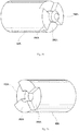
Fig. 1 is a schematic plan view illustrating a transfer apparatus according to a first embodiment of the invention. -
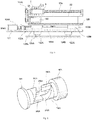
Fig. 2 is a schematic side view illustrating the transfer apparatus according to the first embodiment of the invention. -
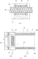
Fig. 3 is a schematic view illustrating a rod-shaped member and an opposite member according to the first embodiment of the invention. -
Fig. 4 is a schematic plan view illustrating the transfer apparatus according to the first embodiment of the invention. -
Fig. 5 is a schematic side view illustrating the transfer apparatus according to the first embodiment of the invention. -
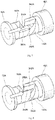
Fig. 6 is a schematic view illustrating a coupler according to the first embodiment of the invention. -
Fig. 7 is a schematic view illustrating the coupler according to the first embodiment of the invention. -
Fig. 8 is a schematic view illustrating the coupler according to the first embodiment of the invention. -
Fig. 9 is a schematic view illustrating the coupler according to the first embodiment of the invention. -
Fig. 10 is a schematic view illustrating the coupler according to the first embodiment of the invention. -
Fig. 11 is a schematic view illustrating a coupler according to a second embodiment of the invention. -
Fig. 12 is a schematic view illustrating the coupler according to the second embodiment of the invention. -
Fig. 13 is a schematic view illustrating the coupler according to the second embodiment of the invention. -
Fig. 14 is a schematic view illustrating a coupler according to a third embodiment of the invention. -
Fig. 15 is a schematic view illustrating the coupler according to the third embodiment of the invention. -
Fig. 16 is a schematic view illustrating the coupler according to the third embodiment of the invention. -
Fig. 17 is a schematic view illustrating the coupler according to the third embodiment of the invention. -
Fig. 18 is a schematic view illustrating the coupler according to the third embodiment of the invention. -
Fig. 19 is a schematic view illustrating the coupler according to the third embodiment of the invention. -
Fig. 20 is a schematic view illustrating the coupler according to the third embodiment of the invention. -
Fig. 21 is a schematic view illustrating the coupler according to the third embodiment of the invention. -
Fig. 22 is a schematic view illustrating a coupler according to a fourth embodiment of the invention. -
Fig. 23 is a schematic view illustrating the coupler according to the fourth embodiment of the invention. -
Fig. 24 is a schematic view illustrating the coupler according to the fourth embodiment of the invention. -
Fig. 25 is a schematic view illustrating a coupler according to a fifth embodiment of the invention. -
Fig. 26 is a schematic view illustrating the coupler according to the fifth embodiment of the invention. -
Fig. 27 is a schematic view illustrating a rod-shaped member and an opposite member according to a first modification of the embodiment of the invention. -
Fig. 28 is a schematic view illustrating a rod-shaped member and an opposite member according to the first modification of the embodiment of the invention. -
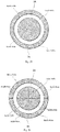
Fig. 29 is a schematic cross-sectional view illustrating a rod-shaped member and an opposite member according to a second modification of the embodiment of the invention. -
Fig. 30 is a schematic cross-sectional view illustrating a rod-shaped member and an opposite member according to the second modification of the embodiment of the invention. -
Fig. 31 is a schematic cross-sectional view illustrating a rod-shaped member and an opposite member according to the second modification of the embodiment of the invention. - Embodiments of the invention will be described below. In the description of the drawings given below, the same or similar parts are denoted by the same or similar reference numerals. However, the drawings are illustrated schematically. Accordingly, specific dimensions and the like should be decided with reference to the following description. It will be appreciated that the relationship or the ratio between dimensions may be different among the drawings.
- As illustrated in
Fig. 1 and Fig. 2 , a transfer apparatus according to a first embodiment of the invention includes first rod-shapedmembers first couplers members members second couplers members first couplers members members - The transfer apparatus further includes an
opposite member 3A, opposed to parts of side surfaces of the first and second rod-shapedmembers opposite member 3B, opposed to parts of side surfaces of the first and second rod-shapedmembers members members opposite member 3A along the first and second rod-shapedmembers members members opposite member 3B along the first and second rod-shapedmembers transfer member 6 that moves together with theopposite members article 5. - The first rod-shaped
members furnace 1 in which thearticle 5 is disposed and that has a temperature-controlled space. The temperature-controlledfurnace 1 is, for example, a freeze drying furnace. For example, ashelf board 7 is disposed in the temperature-controlledfurnace 1 and thearticle 5 including an object to be freeze-dried is disposed on theshelf board 7. Thearticle 5 is, for example, a vial into which a medicine has been poured. - The cylindrical first rod-shaped
member 2A is rotatably held in the temperature-controlledfurnace 1 by a bearing. As illustrated inFig. 3 , the first rod-shapedmember 2A is a magnetic screw including a hard magnetic material and a spiral pattern of S pole magnetized zones and a spiral pattern of N pole magnetized zones are alternately provided on an outer peripheral surface thereof. The first rod-shapedmember 2A may be inserted into a thin-walled pipe 20A made of a nonmagnetic material. Thepipe 20A is made of, for example, stainless steel. The first rod-shapedmember 2A and thepipe 20A are integrated with each other and, when the first rod-shapedmember 2A rotates, thepipe 20A also rotates about the central axis of the first rod-shapedmember 2A. - The cylindrical first rod-shaped
member 2B illustrated inFig. 1 is also rotatably held in parallel with the first rod-shapedmember 2A by a bearing in the temperature-controlledfurnace 1. The structure of the first rod-shapedmember 2B is the same as that of the first rod-shapedmember 2A. - The cylindrical second rod-shaped
members Fig. 2 . The structures of the second rod-shapedmembers member 2A illustrated inFig. 3 . - As illustrated in
Fig. 1 , thefirst coupler 42A is fixed to the end portion of the first rod-shapedmember 2A and thesecond coupler 52A is fixed to the end portion of the second rod-shapedmember 12A. Thefirst coupler 42A and thesecond coupler 52A can be coupled to or separated from each other. Accordingly, the first rod-shapedmember 2A and the second rod-shapedmember 12A can be separated from or coupled serially to each other via the first andsecond couplers members - In addition, the
first coupler 42B is fixed to the end portion of the first rod-shapedmember 2B and thesecond coupler 52B is fixed to the end portion of the second rod-shapedmember 12B. Thefirst coupler 42B and thesecond coupler 52B can be coupled to or separated from each other. Accordingly, the first rod-shapedmember 2B and the second rod-shapedmember 12B can be separated from or coupled serially to each other via the first andsecond couplers members - The
opposite member 3A is a magnetic nut including a hard magnetic material and provided with a hole having an inner circumference larger than outer circumferences of the first and second rod-shapedmembers members opposite member 3A having a nut shape. As illustrated inFig. 3 , a spiral pattern of S pole magnetized zones and a spiral pattern of N pole magnetized zones are alternately provided on an inner peripheral surface of the hole in theopposite member 3A. The pitch of the magnetized zones of theopposite member 3A is substantially the same as the pitch of the magnetized zones of the first and second rod-shapedmembers - Guide rings 31 and 32 such as bushes may be provided on an inner peripheral surface of the
opposite member 3A. The inner circumferences of the guide rings 31 and 32 are smaller than the inner circumference of theopposite member 3A and make contact with the outer peripheral surface of thepipe 20A. Therefore, a constant interval is kept between the magnetized zones of the first and second rod-shapedmembers opposite member 3A. The guide rings 31 and 32 are made of materials having a small friction coefficient, such as fluororesin. - The structure of the
opposite member 3B illustrated inFig. 1 is the same as that of theopposite member 3A. The first and second rod-shapedmembers opposite member 3B having a nut shape. - The
transfer member 6 is fixed between theopposite member 3A and theopposite member 3B. Thearticle 5 to be moved between the table 22 and the temperature-controlledfurnace 1 is disposed in thetransfer member 6. Alternatively, thetransfer member 6 may make contact with thearticle 5 and push thearticle 5 to be transferred. - A driving
device 14A illustrated inFig. 5 includes, for example, a rotating motor. The drivingdevice 14A is fixed to the table 22. In addition, the drivingdevice 14A is connected to a controlling device. The drivingdevice 14A may be covered with a shield or the like that prevents diffusion of dust that may be generated or the like. The drivingdevice 14A and the second rod-shapedmember 12A are connected to each other via, for example, a belt drive. The drivingdevice 14A and the belt drive are covered with, for example, ashield 144A for prevention of dust. For example, a sealing member such as an oil seal is provided in a hole of theshield 144A through which a mandrel connecting a pulley of the belt drive and the second rod-shapedmember 12A penetrates. - The driving
device 14A rotates the second rod-shapedmember 12A about the central axis and changes the relative position between the second rod-shapedmember 12A and theopposite member 3A. In addition, a driving device (not illustrated) rotates the second rod-shapedmember 12B illustrated inFig. 1 andFig. 4 about the central axis and changes the relative position between the second rod-shapedmember 12B and theopposite member 3B. - When the first rod-shaped
member 2A and the second rod-shapedmember 12A are coupled to each other and the first rod-shapedmember 2B and the second rod-shapedmember 12B are connected to each other as illustrated inFig. 1 , the drivingdevice 14A illustrated inFig. 5 and the driving device that drives the second rod-shapedmember 12B illustrated inFig. 1 synchronously rotate the second rod-shapedmembers members members - When the
driving device 14A illustrated inFig. 5 rotates the first and second rod-shapedmembers Fig. 1 , a magnetic force acts between the magnetized zones of the first or second rod-shapedmember opposite member 3A. Theopposite member 3A is fixed to thetransfer member 6 and theopposite member 3B and cannot rotate. Therefore, when the first and second rod-shapedmembers opposite member 3A moves along the central axes of the first and second rod-shapedmembers - In addition, when the driving device rotates the first and second rod-shaped
members member opposite member 3B. Theopposite member 3B is fixed to thetransfer member 6 and theopposite member 3A and cannot rotate. Therefore, when the first and second rod-shapedmembers opposite member 3B moves along the central axes of the first and second rod-shapedmembers - With the movement of the
opposite members transfer member 6 fixed to theopposite members members shelf board 7 or from theshelf board 7 onto the table 22 depending on the rotational directions of the first and second rod-shapedmembers article 5 from the table 22 onto theshelf board 7 or from theshelf board 7 onto the table 22. - As illustrated in
Fig. 4 andFig. 5 , the transfer apparatus further includes abase member 121 positioned below the table 22, a table movement rod-shapedmember 102A at least a pat of which is disposed on thebase member 121 and that includes a magnetic material, a table movement oppositemember 103A that is opposed to a part of a side surface of the table movement rod-shapedmember 102A and includes a magnetic material, and atable driving device 104A that rotates the table movement rod-shapedmember 102A about a central axis and changes the relative position between the table movement rod-shapedmember 102A and the table movement oppositemember 103A. - The table movement rod-shaped
member 102A is held by, for example, a bearing or the like disposed on thebase member 121. Thetable driving device 104A is fixed onto thebase member 121 and covered with, for example, ashield 134A for prevention of dust. Thetable driving device 104A and the table movement rod-shapedmember 102A are connected to each other via, for example, a mandrel. A hole of theshield 134A through which the mandrel penetrates is provided with a sealing member such as, for example, an oil seal. - On the
base member 121, for example, atable movement rail 125A is disposed in parallel with the central axis of the table movement rod-shapedmember 102A. In addition, adriver transmission member 128 is disposed on thebase member 121 viaguides table movement rail 125A. Thedrive transmission member 128 is fixed to the table movement oppositemember 103A and the table 22. - When the
table driving device 104A rotates the table movement rod-shapedmember 102A, the table movement oppositemember 103A moves along the central axis of the table movement rod-shapedmember 102A by a magnetic force. With this, thedrive transmission member 128 fixed to the table movement oppositemember 103A moves along the central axis of the table movement rod-shapedmember 102A. Furthermore, the table 22 fixed to thedrive transmission member 128 moves along the central axis of the table movement rod-shapedmember 102A. - On the
base member 121, another set of a table driving device, a table movement rod-shaped member, and a table movement opposite member may be disposed in parallel with thetable driving device 104A, the table movement rod-shapedmember 102A, and the table movement oppositemember 103A. - When the
first couplers second couplers Fig. 1 are coupled to each other, the table 22 is moved in the direction toward the temperature-controlledfurnace 1 to bring the table 22 close to the temperature-controlledfurnace 1. The table 22 and the temperature-controlledfurnace 1 may be couplable to each other. This brings the second rod-shapedmembers members furnace 1. - For example, when the door of the temperature-controlled
furnace 1 is opened, thefirst couplers second couplers article 5 to move from the table 22 onto theshelf board 7 or from theshelf board 7 onto the table 22 when the temperature-controlledfurnace 1 is opened. - When the
first couplers second couplers furnace 1 to move the table 22 away from the temperature-controlledfurnace 1. This moves the second rod-shapedmembers members furnace 1. - For example, after the
article 5 is moved into the temperature-controlledfurnace 1 or when the temperature-controlledfurnace 1 is not used, thefirst couplers second couplers furnace 1 to be closed. - For example,
wheels 123A and 123B illustrated inFig. 5 may be provided on a bottom surface side of thebase member 121. Thewheels 123A and 123B may rotate onfloor rails member 102A. The table 22 can be moved in the orthogonal direction with respect to the central axis of the table movement rod-shapedmember 102A via thewheels 123A and 123B. - As illustrated in
Fig. 6 , the first andsecond couplers spiral structures spiral structures members - The
spiral structure 142A of thefirst coupler 42A has a spiralcurved surface 242A. The spiral curvedsurface 242A has, for example, a spiral shape formed along the cylindrical surface and thespiral structure 142A may have, for example, one set of spiralcurved surfaces 242A that are 2-fold symmetric. Each of the one set of spiralcurved surfaces 242A is wound by a half turn. Thefirst coupler 42A further includes aflat surface 342A that is parallel with the central axis of the first rod-shapedmember 2A. Theflat surface 342A is orthogonal to the rotational direction of thefirst coupler 42A. For example, the end portion of the spiralcurved surface 242A makes contact with theflat surface 342A. - The
spiral structure 152A of thesecond coupler 52A has a spiralcurved surface 252A. The spiral curvedsurface 252A has, for example, a spiral shape formed along the cylindrical surface and thespiral structure 152A may have, for example, one set of spiralcurved surfaces 252A that are 2-fold symmetric. Each of the one set of spiralcurved surfaces 252A is wound by a half turn. Thesecond coupler 52A further includes aflat surface 352A that is parallel with the central axis of the second rod-shapedmember 12A. Theflat surface 352A is orthogonal to the rotational direction of thesecond coupler 52A. For example, the end portion of the spiralcurved surface 252A makes contact with theflat surface 352A. - When the
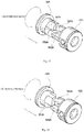
first coupler 42A and thesecond coupler 52A are coupled to each other, as illustrated inFig. 7 to Fig. 10 , for example, thesecond coupler 52A is brought close to thefirst coupler 42A by moving thesecond coupler 52A in the direction of the central axis of the second rod-shapedmember 12A while rotating thesecond coupler 52A. Thesecond coupler 52A is rotated in a direction in which theflat surface 352A of thesecond coupler 52A comes close to theflat surface 342A of thefirst coupler 42A. - The approach speed and the rotational speed of the
second coupler 52A are controlled so that the angle formed by the flat surface orthogonal to the central axis of thesecond coupler 52A and the spiral line drawn by the track of the end portion of the spiralcurved surface 252A when thesecond coupler 52A comes close while rotating is smaller than the angle formed by the flat surface orthogonal to the central axis of thefirst coupler 42A and the spiral line of the spiralcurved surface 242A. As illustrated inFig. 8 andFig. 9 , when theflat surface 352A of thesecond coupler 52A makes contact with theflat surface 342A of thefirst coupler 42A by inserting the end portion of thespiral structure 152A of thesecond coupler 52A into a deep portion of thespiral structure 142A of thefirst coupler 42A so that the end portion of the spiralcurved surface 252A of thesecond coupler 52A does not collide with the spiralcurved surface 242A of thefirst coupler 42A, thesecond coupler 52A and thefirst coupler 42A rotate together with a predetermined relative angle kept. When thesecond coupler 52A is further brought close to thefirst coupler 42A, the spiralcurved surface 252A of thesecond coupler 52A makes contact with the spiralcurved surface 242A of thefirst coupler 42A, thespiral structure 142A engages with thespiral structure 152A, and thesecond coupler 52A and thefirst coupler 42A are coupled to each other as illustrated inFig. 10 . - After the coupling, by rotating the second rod-shaped
member 12A without moving the second rod-shapedmember 12A in the direction of the central axis of the second rod-shapedmember 12A, a rotating force or a torque is transmitted to the first rod-shapedmember 2A fixed to thefirst coupler 42A coupled to thesecond coupler 52A. - Since the first and
second couplers second couplers second couplers member 2A coincides with the phase of the spiral pattern of the second rod-shapedmember 12A and the spiral pattern of the second rod-shapedmember 12A is present on an extension of the spiral pattern of the first rod-shapedmember 2A. - Therefore, when the first and
second couplers opposite member 3A can move smoothly from the first rod-shapedmember 2A to the second rod-shapedmember 12A or from the second rod-shapedmember 12A to the first rod-shapedmember 2A by straddling the first andsecond couplers - When the
first coupler 42A and thesecond coupler 52A are separated from each other, thesecond coupler 52A is moved away from thefirst coupler 42A without rotating thesecond coupler 52A. Alternatively, thesecond coupler 52A is moved away from thefirst coupler 42A while rotating thesecond coupler 52A in a direction in which theflat surface 352A of thesecond coupler 52A is separated from theflat surface 342A of thefirst coupler 42A. - The first and
second couplers Fig. 1 are also coupled to or separated from each other as in the first andsecond couplers - In the transfer apparatus according to the first embodiment described above, a driving force is transmitted between the first and second rod-shaped
members opposite member 3A and between the first and second rod-shapedmembers opposite member 3B in a non-contact manner by a magnetic force. Accordingly, when a driving force is transmitted between the rod-shaped members and the opposite member, heat and dust are unlikely to be generated. Therefore, even when the first rod-shapedmembers opposite members furnace 1, an influence of heat generation in the temperature-controlled space can be suppressed and the temperature-controlled space can be kept clean. - In addition, the first rod-shaped
members members members furnace 1. Therefore, even if dust is generated in the driving device, the dust is unlikely to enter the temperature-controlled space of the temperature-controlledfurnace 1. In addition, if the driving device is disposed inside the temperature-controlled furnace, a temperature distribution may become uneven inside the temperature-controlled furnace such as a freeze drying furnace due to the heated driving device. In this case, the quality of a plurality of articles disposed in the temperature-controlled furnace may become uneven. In contrast, in the transfer apparatus according to the first embodiment, since the driving device is disposed outside the temperature-controlled space of the temperature-controlledfurnace 1, temperature unevenness is unlikely to occur inside the temperature-controlledfurnace 1. - Furthermore, in the transfer apparatus according to the first embodiment, it is possible to separate the first and
second couplers second couplers article 5 into the temperature-controlledfurnace 1. Therefore, the temperature-controlled space of the temperature-controlledfurnace 1 can be hermetically sealed. Accordingly, the transfer apparatus according to the first embodiment can keep the inside of the temperature-controlledfurnace 1 clean and suppress the temperature unevenness in the temperature-controlledfurnace 1. - In a transfer apparatus according to a second embodiment, as illustrated in
Fig. 11 to Fig. 13 , aprojection portion 452A such as a pin is provided on the spiralcurved surface 252A of thesecond coupler 52A. Theprojection portion 452A is provided in parallel with the direction of the central axis of the second rod-shapedmember 12A. In addition, aconcave portion 442A such as a pin hole is provided in the spiralcurved surface 242A of thefirst coupler 42A. Theconcave portion 442A is provided in parallel with the direction of the central axis of the first rod-shapedmember 2A. Theconcave portion 442A provided in thefirst coupler 42A and theprojection portion 452A provided in thesecond coupler 52A have shapes that can engage with each other and theprojection portion 452A provided in thesecond coupler 52A is inserted into theconcave portion 442A provided in thefirst coupler 42A. - The other components of the transfer apparatus according to the second embodiment are the same as those of the first embodiment.
- When the
first coupler 42A and thesecond coupler 52A are coupled to each other, for example, thesecond coupler 52A is brought close to thefirst coupler 42A by moving thesecond coupler 52A in the direction of the central axis of the second rod-shapedmember 12A while rotating thesecond coupler 52A. - As in the first embodiment, when the
flat surface 352A of thesecond coupler 52A makes contact with theflat surface 342A of thefirst coupler 42A while controlling the approach speed and the rotational speed of thesecond coupler 52A so that the end portion of the spiralcurved surface 252A of thesecond coupler 52A does not collide with the spiralcurved surface 242A of thefirst coupler 42A, thesecond coupler 52A and thefirst coupler 42A rotate together with a predetermined relative angle kept. When thesecond coupler 52A further comes close to thefirst coupler 42A, then theprojection portion 452A provided in thesecond coupler 52A is inserted into theconcave portion 442A provided in thefirst coupler 42A, the spiralcurved surface 252A of thesecond coupler 52A makes contact with the spiralcurved surface 242A of thefirst coupler 42A, and thesecond coupler 52A and thefirst coupler 42A are coupled to each other as illustrated inFig. 13 . - After the coupling, by rotating the second rod-shaped
member 12A without moving the second rod-shapedmember 12A in the direction of the central axis of the second rod-shapedmember 12A, a rotating force or a torque is transmitted to the first rod-shapedmember 2A fixed to thefirst coupler 42A. - For example, when the second rod-shaped
member 12A is rotated in an outside direction with respect to theflat surface 352A of thesecond coupler 52A, theflat surface 352A of thesecond coupler 52A applies a rotating force or a torque to theflat surface 342A of thefirst coupler 42A and the first rod-shapedmember 2A rotates in synchronization with the second rod-shapedmember 12A. - Alternatively, when the second rod-shaped
member 12A is rotated in an inside direction with respect to theflat surface 352A of thesecond coupler 52A, the outer wall of theprojection portion 452A of thesecond coupler 52A applies a rotating force or a torque to the inner wall of theconcave portion 442A of thesecond coupler 42A and the first rod-shapedmember 2A rotates in synchronization with the second rod-shapedmember 12A. - When the
first coupler 42A and thesecond coupler 52A are separated from each other, thesecond coupler 52A is moved in a direction opposite to thefirst coupler 42A without being rotated. When the spiralcurved surface 242A of thefirst coupler 42A is provided with a concave portion and the spiralcurved surface 252A of thesecond coupler 52A is provided with a projection portion, if the number of turns of thespiral structure 142A and the number of turns of thespiral structure 152A are one or less, thefirst coupler 42A and thesecond coupler 52A are easily separated from each other. - When the
projection portion 452A and theconcave portion 442A in parallel with the first and second rod-shapedmembers member 12A is rotated in an inside direction with respect to theflat surface 352A of thesecond coupler 52A, a rotating force or a torque is transmitted from the spiralcurved surface 252A of thesecond coupler 52A to the spiralcurved surface 242A of thefirst coupler 42A. At this time, a reactive force that depends on the inclined angles of the spiralcurved surfaces members second couplers - When a gap is generated between the first and
second couplers member 12A may not be transmitted sufficiently to the first rod-shapedmember 2A. In addition, when a gap is generated between the first andsecond couplers member 2A is not present on an extension of the spiral pattern of the second rod-shapedmember 12A and the movement position of thetransfer member 6 may not be controlled accurately. - In contrast, since a rotating force or a torque is transmitted via the
projection portion 452A and theconcave portion 442A provided in parallel with the central axes of the first and second rod-shapedmembers member 12A in the transfer apparatus according to the second embodiment, the generation of a reactive force in the directions of the central axes can be suppressed. - It should be noted here that the spiral
curved surface 242A of thefirst coupler 42A may be provided with the projection portion and the spiralcurved surface 252A of thesecond coupler 52A may be provided with the concave portion. - In a transfer apparatus according to a third embodiment, as illustrated in
Fig. 14 , thesecond coupler 52A includes the firstflat surface 352A that is parallel with directions of the central axes of the first and second rod-shapedmembers members flat surface 552A that is oriented to the second rotational direction opposite to the first rotational direction. For example, in the end portion of thesecond coupler 52A, thespiral structure 152A projects from abase portion 652A having the first and secondflat surfaces - As illustrated in
Fig. 15 , thefirst coupler 42A has a structure similar to that of thesecond coupler 52A, includes the firstflat surface 342A oriented in the first rotational direction of the first and second rod-shapedmembers flat surface 542A oriented in the second rotational direction opposite to the first rotational direction, and engages with thesecond coupler 52A. - The other components of the transfer apparatus according to the third embodiment are the same as those of the first embodiment.
- When the
first coupler 42A and thesecond coupler 52A are coupled to each other, for example, thesecond coupler 52A is brought close to thefirst coupler 42A by moving thesecond coupler 52A in the direction of the central axis of the second rod-shapedmember 12A while rotating thesecond coupler 52A, as illustrated inFig. 15 to Fig. 19 . - When the
second coupler 52A makes contact with thefirst coupler 42A at any relative angle and thesecond coupler 52A is brought close to thefirst coupler 42A while rotating thesecond coupler 52A as illustrated inFig. 15 and Fig. 16 , the end portion of thespiral structure 152A of thesecond coupler 52A is inserted into the concave portion of thespiral structure 142A of thefirst coupler 42A as illustrated inFig. 17 and Fig. 18 . - Furthermore, the first
flat surface 352A of thesecond coupler 52A makes contact with the secondflat surface 542A of thefirst coupler 42A as illustrated inFig. 19 and Fig. 20 , the secondflat surface 552A of thesecond coupler 52A makes contact with the firstflat surface 342A of thefirst coupler 42A as illustrated inFig. 21 , and thesecond coupler 52A and thefirst coupler 42A are coupled to each other. - After the coupling, by rotating the second rod-shaped
member 12A without moving the second rod-shapedmember 12A in the direction of the central axis of the second rod-shapedmember 12A, a rotating force or a torque is transmitted to the first rod-shapedmember 2A fixed to thefirst coupler 42A. - Specifically, when the second rod-shaped
member 12A is rotated in the first rotational direction, a rotating force or a torque is transmitted from the firstflat surface 352A of thesecond coupler 52A illustrated inFig. 20 to the secondflat surface 542A of thefirst coupler 42A. In addition, when the second rod-shapedmember 12A is rotated in the second rotational direction, a rotating force or a torque is transmitted from the secondflat surface 552A of thesecond coupler 52A illustrated inFig. 21 to the firstflat surface 342A of thefirst coupler 42A. - When the
first coupler 42A and thesecond coupler 52A are separated from each other, thesecond coupler 52A is moved in a direction opposite to thefirst coupler 42A without rotating thesecond coupler 52A. - In the transfer apparatus according to the third embodiment, since a rotating force or a torque is transmitted to the
first coupler 42A via one of the first and secondflat surfaces second coupler 52A regardless of the rotational direction of the second rod-shapedmember 12A, the generation of a reactive force in the direction of the central axis can be suppressed. - In a transfer apparatus according to a fourth embodiment, the first and
second couplers engagement structures Fig. 22 . In the fourth embodiment, theengagement structures engagement structure 162A has a concave portion with inner walls facing each other. In addition, theengagement structure 172A has a projection portion to be inserted into the concave portion of theengagement structure 162A. However, theengagement structures second couplers - The
second coupler 52A has, for example, acylindrical member 372A that has a central axis aligned with the direction of the central axis of the second rod-shapedmember 12A and amandrel member 472A, inserted into a hollow portion of thecylindrical member 372A, that is movable in the direction of the central axis of the second rod-shapedmember 12A. Themandrel member 472A may be provided with aguide 572A that prevents the rotation of themandrel member 472A in thecylindrical member 372A and restricts the movement range in the direction of the central axis. Theengagement structure 172A is fixed to the end portion of themandrel member 472A. - The
second coupler 42A further includes anelastic member 272A with which the first andsecond couplers second couplers elastic member 272A is, for example, a coil spring wound around themandrel member 472A and disposed between thecylindrical member 372A and theengagement structure 172A. - The other components of the transfer apparatus according to the fourth embodiment are the same as those of the first embodiment.
- When the
first coupler 42A and thesecond coupler 52A are coupled to each other, for example, thesecond coupler 52A is brought close to thefirst coupler 42A by moving thesecond coupler 52A in the direction of the central axis of the second rod-shapedmember 12A, as illustrated inFig. 23 andFig. 24 . At this time, thesecond coupler 52A may be brought close to thefirst coupler 42A while rotating thesecond coupler 52A or thesecond coupler 52A may be brought close to thefirst coupler 42A without rotating thesecond coupler 52A. - When the
second coupler 52A makes contact with thefirst coupler 42A at any relative angle and theengagement structures second coupler 52A is further brought close to thefirst coupler 42A, theengagement structures elastic member 272A contracts as illustrated inFig. 23 . - When the
second coupler 52A is rotated at this time, if the relative angle at which theengagement structures elastic member 272A is released and theengagement structure 172A is pushed into theengagement structure 162A. This couples thefirst coupler 42A and thesecond coupler 52A to each other. - In the transfer apparatus according to the fourth embodiment described above, the first and
second couplers member 2A in the direction of the central axis. - Although the example in which the
second coupler 42A has theelastic member 272A is described above, the first coupler may have the elastic member. - In a transfer apparatus according to a fifth embodiment, the first and
second couplers engagement structures Fig. 25 and Fig. 26 . In the fifth embodiment, theengagement structures engagement structures second couplers engagement structures second couplers - For example, as illustrated in
Fig. 26 , theengagement structure 182A of thefirst coupler 42A has aconvex surface 282A with the first magnetic pole and aconcave surface 382A with the second magnetic pole, which is a pole different from the first magnetic pole. In addition, as illustrated inFig. 25 , theengagement structure 192A of thesecond coupler 52A has aconvex surface 292A with the first magnetic pole and aconcave surface 392A with the second magnetic pole. When the first magnetic pole is a north pole, the second magnetic pole is a south pole. In contrast, when the first magnetic pole is a south pole, the second magnetic pole is a north pole. - The other components of the transfer apparatus according to the fifth embodiment are the same as those of the first embodiment.
- When the
first coupler 42A and thesecond coupler 52A are coupled to each other, thesecond coupler 52A is brought close to thefirst coupler 42A by, for example, moving thesecond coupler 52A in the direction of the central axis of the second rod-shapedmember 12A. At this time, thesecond coupler 52A may be brought close to thefirst coupler 42A while rotating thesecond coupler 52A or thesecond coupler 52A may be brought close to thefirst coupler 42A without rotating thesecond coupler 52A. - Even when the
second coupler 52A makes contact with thefirst coupler 42A at any relative angle and theengagement structures convex surface 282A of thefirst coupler 42A that has the first magnetic pole and theconcave surface 392A of thesecond coupler 52A that has the second magnetic pole attract each other and theconcave surface 382A of thefirst coupler 42A that has the second magnetic pole and theconvex surface 292A of thesecond coupler 52A that has the first magnetic pole attract each other. Alternatively, the convex surface 282 of thefirst coupler 42A that has the first magnetic pole and theconvex surface 292A of thesecond coupler 52A that has the first magnetic pole repel each other and theconcave surface 382A of thefirst coupler 42A that has the second magnetic pole and theconcave surface 392A of thesecond coupler 52A that has the second magnetic pole repel each other. - Therefore, the
engagement structures second couplers convex surface 282A of thefirst coupler 42A that has the first magnetic pole makes contact with theconcave surface 392A of thesecond coupler 52A that has the second magnetic pole, and theconcave surface 382A of thefirst coupler 42A that has the second magnetic pole makes contact with theconvex surface 292A of thesecond coupler 52A that has the first magnetic pole. - The structures of the rod-shaped
member 2A and theopposite member 3A are not limited to the example illustrated inFig. 3 . For example, as illustrated inFig. 27 , the first rod-shapedmember 2A may be formed of a soft magnetic material having a spiral pattern of threads. The structure of theopposite member 3A is the same as that inFig. 3 . The pitch of the threads of the first rod-shapedmember 2A illustrated inFig. 27 is substantially the same as the pitch of the magnetized zones of theopposite member 3A. The first rod-shapedmember 2A having a spiral pattern of threads may be inserted into the thin-walled pipe 20A made of a nonmagnetic material. This can prevent foreign matters from adhering to the threaded groove of the first rod-shapedmember 2A. When the first rod-shapedmember 2A rotates, a magnetic force acts between the threads of the first rod-shapedmember 2A and the magnetized zones of theopposite member 3A and theopposite member 3A moves. - Alternatively, as illustrated in
Fig. 28 , theopposite member 3A may be formed of a soft magnetic material having a spiral pattern of threads. The surface of a threaded hole in theopposite member 3A may be covered with a thin-walled pipe 30A made of a nonmagnetic material. This can prevent foreign matters from adhering to the threaded groove of theopposite member 3A. The structure of the first rod-shapedmember 2A is the same as that inFig. 3 . The pitch of the threads of theopposite member 3A illustrated inFig. 28 is substantially the same as the pitch of the magnetized zones of the first rod-shapedmember 2A. When the first rod-shapedmember 2A rotates, a magnetic force acts between the magnetized zones of the first rod-shapedmember 2A and the threads of theopposite member 3A and theopposite member 3A moves. - The first rod-shaped
member 2B, the second rod-shapedmembers opposite member 3B illustrated inFig. 1 may also have structures as illustrated inFig. 27 or Fig. 28 . - When the first and second rod-shaped
members opposite member 3A include hard magnetic materials and the number of poles in a combination of the first or second rod-shapedmember opposite member 3A is 2n (where n is a natural number) inFig. 1 , the first andsecond couplers second couplers - Here, the number of poles represents the number of combinations of a north pole and a south pole. For example, when as illustrated in
Fig. 29 , one combination of a north pole and a south pole is present in each of the first rod-shapedmember 2A and theopposite member 3A, the number of magnetic poles is 2(= 2 × 1). In this case, the first andsecond couplers - When two combinations of a north pole and a south pole are present in each of the first rod-shaped
member 2A and theopposite member 3A as illustrated inFig. 30 , the number of magnetic poles is 4 (= 2 × 2). In this case, the first andsecond couplers - When four combinations of a north pole and a south pole are present in each of the first rod-shaped
member 2A and theopposite member 3A as illustrated inFig. 31 , the number of magnetic poles is 8 (= 2 × 4). In this case, the first andsecond couplers - Alternatively, when one of the first and second rod-shaped
members opposite member 3A may include a hard magnetic material, the other may include a soft magnetic material, and the number of poles in a combination of the first or second rod-shapedmember opposite member 3A is 2n (where n represents a natural number), the first andsecond couplers - Although the invention has been described by embodiments as described above, it should not be understood that the description and the drawings that are parts of the disclosure limit the invention. It must be apparent to those skilled in the art that various alternative embodiments, examples, and operational techniques are clarified based on the disclosure. For example, the articles transferred to or from the furnace are not limited to the inclusion of medicines, but may include foods, beverages, precision parts, etc., as well as any articles to be transferred to or from the furnace. In addition, the furnace in which the first rod-shaped
members -
- 1: temperature-controlled furnace
- 2A, 2B: first rod-shaped member
- 3A, 3B: opposite member
- 5: article
- 6: transfer member
- 7: shelf board
- 12A, 12B: second rod-shaped member
- 14A: driving device
- 20A, 30A: thin-walled pipe
- 22: table
- 31: guide ring
- 42A, 42B: first coupler
- 52A, 52B: second coupler
- 102A: table movement rod-shaped member
- 103A: table movement opposite member
- 104A: table driving device
- 121: base member
- 123A, 123B: wheel
- 124A, 124B: floor rail
- 125A: table movement rail
- 126A, 126B: guide
- 128: drive transmission member
- 134A, 144A: shield
- 142A, 152A: spiral structure
- 162A, 172A, 182A, 192A: engagement structure
- 242A, 252A: spiral curved surface
- 272A: elastic member
- 282A, 292A: convex surface
- 342A, 352A, 542A, 552A: flat surface
- 372A: cylindrical member
- 382A, 392A: concave surface
- 442A: concave portion
- 452A: projection portion
- 472A: mandrel member
- 572A: guide
- 652A: base portion
Claims (10)
- A transfer apparatus comprising:a first rod-shaped member that includes a magnetic material, the first rod-shaped member being provided with a spiral pattern;a first coupler that is fixed to an end portion of the first rod-shaped member;a second rod-shaped member that includes a magnetic material, the second rod-shaped member being provided with a spiral pattern;a second coupler that is fixed to an end portion of the second rod-shaped member, the second coupler being coupled to the first coupler so as to make a relative angle between the spiral pattern of the first rod-shaped member and the spiral pattern of the second rod-shaped member constant when coupled to each other; an opposite member that is opposed to parts of side surfaces of the first and second rod-shaped members, the opposite member including a magnetic material; anda driving device configured to rotate the first and second rod-shaped members about central axes of the first and second rod-shaped members and move the opposite member along the first and second rod-shaped members.
- The transfer apparatus according to claim 1,
wherein the first and second couplers are coupled to each other by bringing the first and second rod-shaped members close to each other while rotating at least one of the first and second rod-shaped members. - The transfer apparatus according to claim 1 or 2,
wherein the first and second couplers have spiral structures that engage with each other. - The transfer apparatus according to claim 3,
wherein a spiral curved surface of the spiral structure of one of the first and second couplers is provided with a projection portion and a spiral curved surface of the spiral structure of the other of the first and second couplers is provided with a concave portion into which the projection portion is inserted. - The transfer apparatus according to claim 3 or 4,
wherein the first and second couplers have first flat surfaces that are parallel with directions of the central axes of the first and second rod-shaped members and oriented to a first rotational direction of the first and second rod-shaped members and second flat surfaces that are parallel with the directions of the central axes of the first and second rod-shaped members and oriented to a second rotational direction of the first and second rod-shaped members. - The transfer apparatus according to claim 1 or 2,
wherein the first and second couplers have engagement structures that engage with each other and
at least one of the first and second couplers has an elastic member that contracts when the first and second couplers come into contact with each other and the first and second couplers do not engage with each other. - The transfer apparatus according to claim 1 or 2,
wherein the first and second couplers have engagement structures that engage with each other and
the engagement structures change a relative angle between the first and second couplers using at least one of an attraction force between different magnetic poles and a repulsion force between identical magnetic poles. - The transfer apparatus according to any one of claims 1, 2, and 7,
wherein each of the first and second couplers has a convex surface having a first magnetic pole and a concave surface having a second magnetic pole. - The transfer apparatus according to claim 1 or 2,
wherein the first and second rod-shaped members and the opposite member include hard magnetic materials and,
when the number of poles in a combination of the first or second rod-shaped member and the opposite member is 2n (where n represents a natural number), the first and second couplers are configured to be couplable to each other every relative rotation by 360 × m/n degrees (where m represents a natural number). - The transfer apparatus according to claim 1 or 2,
wherein one of the first and second rod-shaped members and the opposite member includes a hard magnetic material and the other includes a soft magnetic material and,
when the number of poles in a combination between the first or second rod-shaped member and the opposite member is 2n (where n represents a natural number), the first and second couplers are configured to be couplable to each other every relative rotation by 180 × m/n degrees (where m represents a natural number).
Applications Claiming Priority (1)
| Application Number | Priority Date | Filing Date | Title |
|---|---|---|---|
| PCT/JP2016/072796 WO2018025348A1 (en) | 2016-08-03 | 2016-08-03 | Conveying device |
Publications (3)
| Publication Number | Publication Date |
|---|---|
| EP3495690A1 true EP3495690A1 (en) | 2019-06-12 |
| EP3495690A4 EP3495690A4 (en) | 2020-03-18 |
| EP3495690B1 EP3495690B1 (en) | 2022-08-31 |
Family
ID=61074081
Family Applications (1)
| Application Number | Title | Priority Date | Filing Date |
|---|---|---|---|
| EP16911609.2A Active EP3495690B1 (en) | 2016-08-03 | 2016-08-03 | Conveying device |
Country Status (4)
| Country | Link |
|---|---|
| US (1) | US20190195285A1 (en) |
| EP (1) | EP3495690B1 (en) |
| CN (1) | CN109642648B (en) |
| WO (1) | WO2018025348A1 (en) |
Families Citing this family (1)
| Publication number | Priority date | Publication date | Assignee | Title |
|---|---|---|---|---|
| WO2026025569A1 (en) * | 2024-07-30 | 2026-02-05 | 石家庄健牧饲料有限公司 | Damping device capable of converting vibrational energy into electrical energy |
Family Cites Families (22)
| Publication number | Priority date | Publication date | Assignee | Title |
|---|---|---|---|---|
| JPS4730613U (en) * | 1971-04-26 | 1972-12-07 | ||
| DE2412819C3 (en) * | 1974-03-16 | 1981-05-27 | Deere & Co. Niederlassung Deere & Co. European Office, 6800 Mannheim, Moline, Ill. | Shaft coupling |
| JPS6173994U (en) * | 1984-10-20 | 1986-05-19 | ||
| JPS61193047U (en) * | 1985-05-21 | 1986-12-01 | ||
| AT392133B (en) * | 1989-03-07 | 1991-01-25 | Steyr Daimler Puch Ag | CLAW CLUTCH |
| US5085094A (en) * | 1990-11-08 | 1992-02-04 | Gmi Holdings, Inc. | Door operator coupling assembly |
| KR100224117B1 (en) * | 1995-08-29 | 1999-10-15 | 아마노 시게루 | Magnetic screw carrier device |
| CN2256054Y (en) * | 1996-05-17 | 1997-06-11 | 赵文英 | Same diameter axial docking device |
| US5852949A (en) * | 1996-07-30 | 1998-12-29 | Thermo Fibertek Inc. | Segmented screw traversing mechanism |
| US5881649A (en) * | 1996-08-13 | 1999-03-16 | Anelva Corporation | Magnetic transfer system, power transmission mechanism of the magnetic transfer system, and rotational driving member used for the system |
| JPH11278663A (en) * | 1998-03-26 | 1999-10-12 | Ckd Corp | Magnetic screw conveyor |
| EP1080528B1 (en) * | 1998-05-29 | 2005-07-27 | Joseph Peter William Baker | Motion transmission devices |
| JPH11314756A (en) * | 1999-03-23 | 1999-11-16 | Ckd Corp | Magnetic screw conveyor |
| JP2002089649A (en) * | 2000-09-18 | 2002-03-27 | Ckd Corp | Slide transport device |
| JP2005169163A (en) * | 2003-12-08 | 2005-06-30 | Shoei Kurotaki | Joint mechanism of rod-like member |
| JP5422175B2 (en) * | 2008-11-05 | 2014-02-19 | 三菱重工業株式会社 | Linear actuator |
| US8485334B2 (en) * | 2011-01-28 | 2013-07-16 | Hiwin Mikrosystem Corp. | Clutch mechanism with overload protection |
| DE102013202298A1 (en) * | 2013-02-13 | 2014-08-14 | Mahle International Gmbh | Pump, particularly coolant pump, for use in motor vehicle for conveying fluid, has coupling device, which has coupling element with latching contour and another coupling element with counter-latching contour |
| JP6184346B2 (en) * | 2014-03-07 | 2017-08-23 | 日立Geニュークリア・エナジー株式会社 | Control rod drive mechanism |
| JP6266488B2 (en) * | 2014-10-30 | 2018-01-24 | アズビル株式会社 | Temperature management device, transfer device, and transfer stand |
| CN108883881B (en) * | 2016-03-25 | 2020-04-07 | 阿自倍尔株式会社 | Conveying device and storage device |
| CN108883880B (en) * | 2016-03-25 | 2021-02-09 | 阿自倍尔株式会社 | Conveying device |
-
2016
- 2016-08-03 US US16/322,336 patent/US20190195285A1/en not_active Abandoned
- 2016-08-03 WO PCT/JP2016/072796 patent/WO2018025348A1/en not_active Ceased
- 2016-08-03 EP EP16911609.2A patent/EP3495690B1/en active Active
- 2016-08-03 CN CN201680088346.9A patent/CN109642648B/en active Active
Also Published As
| Publication number | Publication date |
|---|---|
| CN109642648B (en) | 2021-12-21 |
| WO2018025348A1 (en) | 2018-02-08 |
| EP3495690A4 (en) | 2020-03-18 |
| CN109642648A (en) | 2019-04-16 |
| US20190195285A1 (en) | 2019-06-27 |
| EP3495690B1 (en) | 2022-08-31 |
Similar Documents
| Publication | Publication Date | Title |
|---|---|---|
| EP3214397B1 (en) | Temperature management apparatus | |
| CN109906151B (en) | Magnetic coupling device | |
| US9890844B2 (en) | Openable forcipate gear mechanism, forcipate gear open-close mechanism, and winding machine | |
| EP3495690B1 (en) | Conveying device | |
| CN110999050B (en) | Magnetic coupling device | |
| EP3434629B1 (en) | Transfer apparatus | |
| JP2012017776A (en) | Magnetic driving force converter | |
| GB2531706A (en) | Apparatus and method | |
| US10703575B2 (en) | Conveyance device | |
| WO2017163422A1 (en) | Conveying device and storage device | |
| US20190071253A1 (en) | Transfer apparatus and storage apparatus | |
| US7622839B2 (en) | Magnetic belt and roller system | |
| KR100462741B1 (en) | A dynamic force transmission and production device and a conveyer using the dynamic force transmission | |
| US12607644B2 (en) | Laboratory sample container handling apparatus, laboratory automation system, and use | |
| KR200448642Y1 (en) | Magnetic gear bushing | |
| JP2012017777A (en) | Magnetic power transmission device | |
| JPH0775989A (en) | Biaxial independent driving device | |
| JP2006020413A (en) | Magnetic interlocking device and roller conveyor |
Legal Events
| Date | Code | Title | Description |
|---|---|---|---|
| STAA | Information on the status of an ep patent application or granted ep patent |
Free format text: STATUS: THE INTERNATIONAL PUBLICATION HAS BEEN MADE |
|
| PUAI | Public reference made under article 153(3) epc to a published international application that has entered the european phase |
Free format text: ORIGINAL CODE: 0009012 |
|
| STAA | Information on the status of an ep patent application or granted ep patent |
Free format text: STATUS: REQUEST FOR EXAMINATION WAS MADE |
|
| 17P | Request for examination filed |
Effective date: 20190130 |
|
| AK | Designated contracting states |
Kind code of ref document: A1 Designated state(s): AL AT BE BG CH CY CZ DE DK EE ES FI FR GB GR HR HU IE IS IT LI LT LU LV MC MK MT NL NO PL PT RO RS SE SI SK SM TR |
|
| AX | Request for extension of the european patent |
Extension state: BA ME |
|
| DAV | Request for validation of the european patent (deleted) | ||
| DAX | Request for extension of the european patent (deleted) | ||
| A4 | Supplementary search report drawn up and despatched |
Effective date: 20200213 |
|
| RIC1 | Information provided on ipc code assigned before grant |
Ipc: H02K 7/06 20060101ALI20200207BHEP Ipc: F16H 49/00 20060101ALI20200207BHEP Ipc: F16H 25/20 20060101AFI20200207BHEP Ipc: F16H 25/24 20060101ALI20200207BHEP Ipc: F16D 1/00 20060101ALI20200207BHEP |
|
| STAA | Information on the status of an ep patent application or granted ep patent |
Free format text: STATUS: EXAMINATION IS IN PROGRESS |
|
| 17Q | First examination report despatched |
Effective date: 20210310 |
|
| REG | Reference to a national code |
Ref country code: DE Ref legal event code: R079 Ref document number: 602016074747 Country of ref document: DE Free format text: PREVIOUS MAIN CLASS: F16H0025200000 Ipc: F16D0041061000 |
|
| GRAP | Despatch of communication of intention to grant a patent |
Free format text: ORIGINAL CODE: EPIDOSNIGR1 |
|
| STAA | Information on the status of an ep patent application or granted ep patent |
Free format text: STATUS: GRANT OF PATENT IS INTENDED |
|
| RIC1 | Information provided on ipc code assigned before grant |
Ipc: F16H 49/00 20060101ALI20220309BHEP Ipc: F16H 25/24 20060101ALI20220309BHEP Ipc: F16H 25/20 20060101ALI20220309BHEP Ipc: H02K 7/06 20060101ALI20220309BHEP Ipc: F16D 41/061 20060101AFI20220309BHEP |
|
| INTG | Intention to grant announced |
Effective date: 20220406 |
|
| GRAS | Grant fee paid |
Free format text: ORIGINAL CODE: EPIDOSNIGR3 |
|
| GRAA | (expected) grant |
Free format text: ORIGINAL CODE: 0009210 |
|
| STAA | Information on the status of an ep patent application or granted ep patent |
Free format text: STATUS: THE PATENT HAS BEEN GRANTED |
|
| AK | Designated contracting states |
Kind code of ref document: B1 Designated state(s): AL AT BE BG CH CY CZ DE DK EE ES FI FR GB GR HR HU IE IS IT LI LT LU LV MC MK MT NL NO PL PT RO RS SE SI SK SM TR |
|
| REG | Reference to a national code |
Ref country code: CH Ref legal event code: EP Ref country code: GB Ref legal event code: FG4D |
|
| REG | Reference to a national code |
Ref country code: AT Ref legal event code: REF Ref document number: 1515494 Country of ref document: AT Kind code of ref document: T Effective date: 20220915 Ref country code: DE Ref legal event code: R096 Ref document number: 602016074747 Country of ref document: DE |
|
| REG | Reference to a national code |
Ref country code: IE Ref legal event code: FG4D |
|
| REG | Reference to a national code |
Ref country code: LT Ref legal event code: MG9D |
|
| REG | Reference to a national code |
Ref country code: NL Ref legal event code: MP Effective date: 20220831 |
|
| PG25 | Lapsed in a contracting state [announced via postgrant information from national office to epo] |
Ref country code: SE Free format text: LAPSE BECAUSE OF FAILURE TO SUBMIT A TRANSLATION OF THE DESCRIPTION OR TO PAY THE FEE WITHIN THE PRESCRIBED TIME-LIMIT Effective date: 20220831 Ref country code: RS Free format text: LAPSE BECAUSE OF FAILURE TO SUBMIT A TRANSLATION OF THE DESCRIPTION OR TO PAY THE FEE WITHIN THE PRESCRIBED TIME-LIMIT Effective date: 20220831 Ref country code: NO Free format text: LAPSE BECAUSE OF FAILURE TO SUBMIT A TRANSLATION OF THE DESCRIPTION OR TO PAY THE FEE WITHIN THE PRESCRIBED TIME-LIMIT Effective date: 20221130 Ref country code: LV Free format text: LAPSE BECAUSE OF FAILURE TO SUBMIT A TRANSLATION OF THE DESCRIPTION OR TO PAY THE FEE WITHIN THE PRESCRIBED TIME-LIMIT Effective date: 20220831 Ref country code: LT Free format text: LAPSE BECAUSE OF FAILURE TO SUBMIT A TRANSLATION OF THE DESCRIPTION OR TO PAY THE FEE WITHIN THE PRESCRIBED TIME-LIMIT Effective date: 20220831 Ref country code: FI Free format text: LAPSE BECAUSE OF FAILURE TO SUBMIT A TRANSLATION OF THE DESCRIPTION OR TO PAY THE FEE WITHIN THE PRESCRIBED TIME-LIMIT Effective date: 20220831 |
|
| REG | Reference to a national code |
Ref country code: AT Ref legal event code: MK05 Ref document number: 1515494 Country of ref document: AT Kind code of ref document: T Effective date: 20220831 |
|
| PG25 | Lapsed in a contracting state [announced via postgrant information from national office to epo] |
Ref country code: PL Free format text: LAPSE BECAUSE OF FAILURE TO SUBMIT A TRANSLATION OF THE DESCRIPTION OR TO PAY THE FEE WITHIN THE PRESCRIBED TIME-LIMIT Effective date: 20220831 Ref country code: IS Free format text: LAPSE BECAUSE OF FAILURE TO SUBMIT A TRANSLATION OF THE DESCRIPTION OR TO PAY THE FEE WITHIN THE PRESCRIBED TIME-LIMIT Effective date: 20221231 Ref country code: HR Free format text: LAPSE BECAUSE OF FAILURE TO SUBMIT A TRANSLATION OF THE DESCRIPTION OR TO PAY THE FEE WITHIN THE PRESCRIBED TIME-LIMIT Effective date: 20220831 Ref country code: GR Free format text: LAPSE BECAUSE OF FAILURE TO SUBMIT A TRANSLATION OF THE DESCRIPTION OR TO PAY THE FEE WITHIN THE PRESCRIBED TIME-LIMIT Effective date: 20221201 |
|
| PG25 | Lapsed in a contracting state [announced via postgrant information from national office to epo] |
Ref country code: SM Free format text: LAPSE BECAUSE OF FAILURE TO SUBMIT A TRANSLATION OF THE DESCRIPTION OR TO PAY THE FEE WITHIN THE PRESCRIBED TIME-LIMIT Effective date: 20220831 Ref country code: RO Free format text: LAPSE BECAUSE OF FAILURE TO SUBMIT A TRANSLATION OF THE DESCRIPTION OR TO PAY THE FEE WITHIN THE PRESCRIBED TIME-LIMIT Effective date: 20220831 Ref country code: PT Free format text: LAPSE BECAUSE OF FAILURE TO SUBMIT A TRANSLATION OF THE DESCRIPTION OR TO PAY THE FEE WITHIN THE PRESCRIBED TIME-LIMIT Effective date: 20230102 Ref country code: ES Free format text: LAPSE BECAUSE OF FAILURE TO SUBMIT A TRANSLATION OF THE DESCRIPTION OR TO PAY THE FEE WITHIN THE PRESCRIBED TIME-LIMIT Effective date: 20220831 Ref country code: DK Free format text: LAPSE BECAUSE OF FAILURE TO SUBMIT A TRANSLATION OF THE DESCRIPTION OR TO PAY THE FEE WITHIN THE PRESCRIBED TIME-LIMIT Effective date: 20220831 Ref country code: CZ Free format text: LAPSE BECAUSE OF FAILURE TO SUBMIT A TRANSLATION OF THE DESCRIPTION OR TO PAY THE FEE WITHIN THE PRESCRIBED TIME-LIMIT Effective date: 20220831 Ref country code: AT Free format text: LAPSE BECAUSE OF FAILURE TO SUBMIT A TRANSLATION OF THE DESCRIPTION OR TO PAY THE FEE WITHIN THE PRESCRIBED TIME-LIMIT Effective date: 20220831 |
|
| PG25 | Lapsed in a contracting state [announced via postgrant information from national office to epo] |
Ref country code: SK Free format text: LAPSE BECAUSE OF FAILURE TO SUBMIT A TRANSLATION OF THE DESCRIPTION OR TO PAY THE FEE WITHIN THE PRESCRIBED TIME-LIMIT Effective date: 20220831 Ref country code: EE Free format text: LAPSE BECAUSE OF FAILURE TO SUBMIT A TRANSLATION OF THE DESCRIPTION OR TO PAY THE FEE WITHIN THE PRESCRIBED TIME-LIMIT Effective date: 20220831 |
|
| REG | Reference to a national code |
Ref country code: DE Ref legal event code: R097 Ref document number: 602016074747 Country of ref document: DE |
|
| PG25 | Lapsed in a contracting state [announced via postgrant information from national office to epo] |
Ref country code: NL Free format text: LAPSE BECAUSE OF FAILURE TO SUBMIT A TRANSLATION OF THE DESCRIPTION OR TO PAY THE FEE WITHIN THE PRESCRIBED TIME-LIMIT Effective date: 20220831 Ref country code: AL Free format text: LAPSE BECAUSE OF FAILURE TO SUBMIT A TRANSLATION OF THE DESCRIPTION OR TO PAY THE FEE WITHIN THE PRESCRIBED TIME-LIMIT Effective date: 20220831 |
|
| PLBE | No opposition filed within time limit |
Free format text: ORIGINAL CODE: 0009261 |
|
| STAA | Information on the status of an ep patent application or granted ep patent |
Free format text: STATUS: NO OPPOSITION FILED WITHIN TIME LIMIT |
|
| 26N | No opposition filed |
Effective date: 20230601 |
|
| PG25 | Lapsed in a contracting state [announced via postgrant information from national office to epo] |
Ref country code: SI Free format text: LAPSE BECAUSE OF FAILURE TO SUBMIT A TRANSLATION OF THE DESCRIPTION OR TO PAY THE FEE WITHIN THE PRESCRIBED TIME-LIMIT Effective date: 20220831 |
|
| PG25 | Lapsed in a contracting state [announced via postgrant information from national office to epo] |
Ref country code: MC Free format text: LAPSE BECAUSE OF FAILURE TO SUBMIT A TRANSLATION OF THE DESCRIPTION OR TO PAY THE FEE WITHIN THE PRESCRIBED TIME-LIMIT Effective date: 20220831 |
|
| REG | Reference to a national code |
Ref country code: CH Ref legal event code: PL |
|
| PG25 | Lapsed in a contracting state [announced via postgrant information from national office to epo] |
Ref country code: MC Free format text: LAPSE BECAUSE OF FAILURE TO SUBMIT A TRANSLATION OF THE DESCRIPTION OR TO PAY THE FEE WITHIN THE PRESCRIBED TIME-LIMIT Effective date: 20220831 |
|
| PG25 | Lapsed in a contracting state [announced via postgrant information from national office to epo] |
Ref country code: LU Free format text: LAPSE BECAUSE OF NON-PAYMENT OF DUE FEES Effective date: 20230803 |
|
| GBPC | Gb: european patent ceased through non-payment of renewal fee |
Effective date: 20230803 |
|
| PG25 | Lapsed in a contracting state [announced via postgrant information from national office to epo] |
Ref country code: LU Free format text: LAPSE BECAUSE OF NON-PAYMENT OF DUE FEES Effective date: 20230803 Ref country code: CH Free format text: LAPSE BECAUSE OF NON-PAYMENT OF DUE FEES Effective date: 20230831 |
|
| REG | Reference to a national code |
Ref country code: BE Ref legal event code: MM Effective date: 20230831 |
|
| REG | Reference to a national code |
Ref country code: IE Ref legal event code: MM4A |
|
| PG25 | Lapsed in a contracting state [announced via postgrant information from national office to epo] |
Ref country code: IE Free format text: LAPSE BECAUSE OF NON-PAYMENT OF DUE FEES Effective date: 20230803 |
|
| PG25 | Lapsed in a contracting state [announced via postgrant information from national office to epo] |
Ref country code: GB Free format text: LAPSE BECAUSE OF NON-PAYMENT OF DUE FEES Effective date: 20230803 |
|
| PG25 | Lapsed in a contracting state [announced via postgrant information from national office to epo] |
Ref country code: IE Free format text: LAPSE BECAUSE OF NON-PAYMENT OF DUE FEES Effective date: 20230803 Ref country code: GB Free format text: LAPSE BECAUSE OF NON-PAYMENT OF DUE FEES Effective date: 20230803 Ref country code: FR Free format text: LAPSE BECAUSE OF NON-PAYMENT OF DUE FEES Effective date: 20230831 |
|
| PG25 | Lapsed in a contracting state [announced via postgrant information from national office to epo] |
Ref country code: BE Free format text: LAPSE BECAUSE OF NON-PAYMENT OF DUE FEES Effective date: 20230831 |
|
| REG | Reference to a national code |
Ref country code: DE Ref legal event code: R081 Ref document number: 602016074747 Country of ref document: DE Owner name: AZBIL TELSTAR TECHNOLOGIES. S.L., ES Free format text: FORMER OWNER: AZBIL CORPORATION, TOKYO, JP Ref country code: DE Ref legal event code: R081 Ref document number: 602016074747 Country of ref document: DE Owner name: SYNTEGON TELSTAR TECHNOLOGIES, S.L.U., ES Free format text: FORMER OWNER: AZBIL CORPORATION, TOKYO, JP |
|
| PG25 | Lapsed in a contracting state [announced via postgrant information from national office to epo] |
Ref country code: BG Free format text: LAPSE BECAUSE OF FAILURE TO SUBMIT A TRANSLATION OF THE DESCRIPTION OR TO PAY THE FEE WITHIN THE PRESCRIBED TIME-LIMIT Effective date: 20220831 |
|
| PG25 | Lapsed in a contracting state [announced via postgrant information from national office to epo] |
Ref country code: BG Free format text: LAPSE BECAUSE OF FAILURE TO SUBMIT A TRANSLATION OF THE DESCRIPTION OR TO PAY THE FEE WITHIN THE PRESCRIBED TIME-LIMIT Effective date: 20220831 |
|
| PGFP | Annual fee paid to national office [announced via postgrant information from national office to epo] |
Ref country code: IT Payment date: 20241227 Year of fee payment: 10 |
|
| PG25 | Lapsed in a contracting state [announced via postgrant information from national office to epo] |
Ref country code: CY Free format text: LAPSE BECAUSE OF FAILURE TO SUBMIT A TRANSLATION OF THE DESCRIPTION OR TO PAY THE FEE WITHIN THE PRESCRIBED TIME-LIMIT; INVALID AB INITIO Effective date: 20160803 |
|
| REG | Reference to a national code |
Ref country code: DE Ref legal event code: R081 Ref document number: 602016074747 Country of ref document: DE Owner name: SYNTEGON TELSTAR TECHNOLOGIES, S.L.U., ES Free format text: FORMER OWNER: AZBIL TELSTAR TECHNOLOGIES. S.L., TERRASSA, ES |
|
| PG25 | Lapsed in a contracting state [announced via postgrant information from national office to epo] |
Ref country code: HU Free format text: LAPSE BECAUSE OF FAILURE TO SUBMIT A TRANSLATION OF THE DESCRIPTION OR TO PAY THE FEE WITHIN THE PRESCRIBED TIME-LIMIT; INVALID AB INITIO Effective date: 20160803 |
|
| PGFP | Annual fee paid to national office [announced via postgrant information from national office to epo] |
Ref country code: DE Payment date: 20250819 Year of fee payment: 10 |
|
| PG25 | Lapsed in a contracting state [announced via postgrant information from national office to epo] |
Ref country code: TR Free format text: LAPSE BECAUSE OF FAILURE TO SUBMIT A TRANSLATION OF THE DESCRIPTION OR TO PAY THE FEE WITHIN THE PRESCRIBED TIME-LIMIT Effective date: 20220831 |