EP3495648A1 - Power control device, power control system, power control method, and power control program - Google Patents
Power control device, power control system, power control method, and power control program Download PDFInfo
- Publication number
- EP3495648A1 EP3495648A1 EP18194533.8A EP18194533A EP3495648A1 EP 3495648 A1 EP3495648 A1 EP 3495648A1 EP 18194533 A EP18194533 A EP 18194533A EP 3495648 A1 EP3495648 A1 EP 3495648A1
- Authority
- EP
- European Patent Office
- Prior art keywords
- control
- conduction
- electrification
- period
- control channel
- Prior art date
- Legal status (The legal status is an assumption and is not a legal conclusion. Google has not performed a legal analysis and makes no representation as to the accuracy of the status listed.)
- Granted
Links
Images
Classifications
-
- F—MECHANICAL ENGINEERING; LIGHTING; HEATING; WEAPONS; BLASTING
- F02—COMBUSTION ENGINES; HOT-GAS OR COMBUSTION-PRODUCT ENGINE PLANTS
- F02D—CONTROLLING COMBUSTION ENGINES
- F02D41/00—Electrical control of supply of combustible mixture or its constituents
- F02D41/20—Output circuits, e.g. for controlling currents in command coils
-
- F—MECHANICAL ENGINEERING; LIGHTING; HEATING; WEAPONS; BLASTING
- F02—COMBUSTION ENGINES; HOT-GAS OR COMBUSTION-PRODUCT ENGINE PLANTS
- F02P—IGNITION, OTHER THAN COMPRESSION IGNITION, FOR INTERNAL-COMBUSTION ENGINES; TESTING OF IGNITION TIMING IN COMPRESSION-IGNITION ENGINES
- F02P19/00—Incandescent ignition, e.g. during starting of internal combustion engines; Combination of incandescent and spark ignition
- F02P19/02—Incandescent ignition, e.g. during starting of internal combustion engines; Combination of incandescent and spark ignition electric, e.g. layout of circuits of apparatus having glowing plugs
-
- H—ELECTRICITY
- H05—ELECTRIC TECHNIQUES NOT OTHERWISE PROVIDED FOR
- H05B—ELECTRIC HEATING; ELECTRIC LIGHT SOURCES NOT OTHERWISE PROVIDED FOR; CIRCUIT ARRANGEMENTS FOR ELECTRIC LIGHT SOURCES, IN GENERAL
- H05B1/00—Details of electric heating devices
- H05B1/02—Automatic switching arrangements specially adapted to apparatus ; Control of heating devices
- H05B1/0227—Applications
-
- F—MECHANICAL ENGINEERING; LIGHTING; HEATING; WEAPONS; BLASTING
- F02—COMBUSTION ENGINES; HOT-GAS OR COMBUSTION-PRODUCT ENGINE PLANTS
- F02D—CONTROLLING COMBUSTION ENGINES
- F02D41/00—Electrical control of supply of combustible mixture or its constituents
- F02D41/20—Output circuits, e.g. for controlling currents in command coils
- F02D2041/202—Output circuits, e.g. for controlling currents in command coils characterised by the control of the circuit
- F02D2041/2024—Output circuits, e.g. for controlling currents in command coils characterised by the control of the circuit the control switching a load after time-on and time-off pulses
-
- F—MECHANICAL ENGINEERING; LIGHTING; HEATING; WEAPONS; BLASTING
- F02—COMBUSTION ENGINES; HOT-GAS OR COMBUSTION-PRODUCT ENGINE PLANTS
- F02D—CONTROLLING COMBUSTION ENGINES
- F02D41/00—Electrical control of supply of combustible mixture or its constituents
- F02D41/20—Output circuits, e.g. for controlling currents in command coils
- F02D2041/202—Output circuits, e.g. for controlling currents in command coils characterised by the control of the circuit
- F02D2041/2048—Output circuits, e.g. for controlling currents in command coils characterised by the control of the circuit said control involving a limitation, e.g. applying current or voltage limits
Definitions
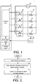
- FIG. 1 is a functional block diagram showing an example of a power control system and a power control device according to an embodiment of the present disclosure.
- a power control device 10 includes a setting part 11, a calculation part 12 and a control part 13.
- the setting part 11 receives settings of a control period Ts and the number n of control channels which simultaneously output conduction control signals.
- the calculation part 12 calculates an upper limit value tdm of an electrification quantity within the time of the control period Ts of each control channel, that is, upper limit value of electrification quantities of a switch element 21, a switch element 22, a switch element 23 and a switch element 24 using the control period Ts, the number n of simultaneously conducted control channels and a total number N of control channels controlled by the power control device 10 in a power control system 1.
- the calculation part 12 calculates a delay time tDN in starting of conduction control of each control channel with respect to a starting time of the control period Ts.
- FIG. 1 is a functional block diagram showing an example of the power control system and the power control device according to an embodiment of the present disclosure.
- the total number N of control channels, the number of switch elements and the number of heaters are 4 will be represented in the following description, the total number N of control channels, the number of switch elements and the number of heaters are not limited thereto as long as they are plural in number.
- the power control system 1 includes the power control device 10, the SSR 20, the heating member 30, a power source 40, and a sensor 50.
- the power control device 10 includes the setting part 11, the calculation part 12 and the control part 13.
- the SSR 20 includes the switch element 21, the switch element 22, the switch element 23 and the switch element 24.
- the heating member 30 includes the heater 31, the heater 32, the heater 33 and the heater 34.
- the switch element 21 and the heater 31 are serially connected to constitute a first serial circuit.
- the switch element 22 and the heater 32 are serially connected to constitute a second serial circuit.
- the switch element 23 and the heater 33 are serially connected to constitute a third serial circuit.
- the switch element 24 and the heater 34 are serially connected to constitute a fourth serial circuit.
- the first serial circuit, the second serial circuit, the third serial circuit and the fourth serial circuit are connected parallel to the power source 40.
- conduction or disconnection of the heater 33 and the power source 40 is controlled and an electrification quantity to the heater 33 is controlled.
- the switch element 24 is closed or opened by receiving a control signal of a control channel CH4 from the control part 13. Accordingly, conduction or disconnection of the heater 34 and the power source 40 is controlled and an electrification quantity to the heater 34 is controlled.
- These electrification quantities are set by conduction time, that is, time durations of the control signals for closing the switch elements.
- the sensor 50 measures a temperature and the like of a heating target of the heating member 30 and outputs measurement data to the calculation part 12.
- the power control device 10 includes the following configuration and executes the following control.
- the setting part 11 outputs the total number N of control channels, the control period Ts, the number n of control channels simultaneously outputting conduction control signals and the delay time ⁇ b between control channels to the calculation part 12.
- the calculation part 12 is realized by an information processing IC and a program installed in the IC.
- the calculation part 12 performs calculation for feedback control of bringing a measured value (measured temperature) from the sensor 50 close to a target value (target temperature) using the measured value and calculates an electrification quantity of each control channel M in the next effective control period Te.
- the calculation part 12 may employ PID control as feedback control.
- a feedback control type is not limited to PID control.
- the calculation part 12 outputs the effective control period Te, the effective electrification quantity (effective conduction time) td, and the delay time tDM in starting of control of the control channel M to the control part 13.
- control part 13 is realized by an information processing IC having a timer function and a program installed in this IC. Meanwhile, the control part 13 may be formed using the IC same as the calculation part 12.
- the control part 13 determines a conduction control signal output period for each control channel using the effective control period Te, the effective electrification quantity (effective conduction time) td, and the delay time tDM in starting of control of the control channel M. That is, the control part 13 executes conduction control and disconnection control for each control channel using the effective control period Te, the effective electrification quantity (effective conduction time) td, and the delay time tDM in starting of control of the control channel M.
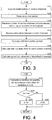
- FIG. 2 is a flowchart showing an example of a power control method according to an embodiment of the present disclosure.
- FIG. 3 is a flowchart showing an example of a setting process and a calculation process in the power control method according to an embodiment of the present disclosure.
- FIG. 4 is a flowchart showing an example of a calculation process in the power control method according to an embodiment of the present disclosure.
- the information processing device executes the process shown in FIG. 2 as a schematic process.
- the information processing device sets control conditions (S11). Specifically, the information processing device calculates the effective control period Te using the total number N of control channels, the control period Ts and the delay time ⁇ b between control channels. In addition, the information processing device calculates the upper limit value tdm of electrification quantities in the effective control period Te using the total number N of control channels, and the number n of control channels simultaneously outputting the conduction control signals. Then, the information processing device calculates the upper limit value tdMm of an electrification quantity of each control channel M by dividing the upper limit value tdm of all electrification quantities by the number n of control channels simultaneously outputting the conduction control signals.
- the information processing device calculates a delay time tD in starting of control for each control channel using the effective control period Te and the total number N of control channels. Further, the information processing device performs calculation for feedback control of bringing a measured value (measured temperature) from the sensor 50 close to a target value (target temperature) using the measured value and calculates an electrification quantity of each control channel M in the next effective control period Te.
- the information processing device calculates an electrification quantity (effective electrification quantity td) for each control channel M (S12). Specifically, the information processing device compares the upper limit value tdMm of the electrification quantity of the control channel M with an electrification quantity obtained through the calculation of feedback control and calculates the electrification quantity (effective electrification quantity td) of each control channel, as described above.
- the information processing device executes control of conduction for each control channel M using the aforementioned control conditions and the electrification quantity (effective electrification quantity td) of each control channel M (S13).
- step S11 setting of the control conditions in step S11 is performed through the process shown in FIG. 3 , for example.
- the information processing device receives the total number N of control channels (S101).
- the information processing device receives the control period Ts (S102).
- the information processing device receives the number n of control channels simultaneously outputting the conduction control signals (S103).
- the information processing device receives the delay time ⁇ b between control channels (S104). Meanwhile, the order of execution of steps S101, S102, S103 and S104 by the information processing device is not limited to the aforementioned order.
- the information processing device calculates the effective control period Te using the above-described method (S105).
- step S12 calculation of the electrification quantity for each control channel in step S12 is executed through the process shown in FIG. 4 .
- the information processing device calculates an electrification quantity tdc according to calculation for feedback control (S201).
- the information processing device compares the electrification quantity tdc according to calculation for feedback control with the upper limit value tdMm of the electrification quantity of the control channel M.
- the information processing device sets the electrification quantity tdc as the effective electrification quantity td (S203) if the electrification quantity tdc is equal to or less than the upper limit value tdMm (S202: YES).
- the information processing device sets the upper limit value tdMm as the effective electrification quantity td (S203) if the electrification quantity tdc is greater than the upper limit value tdMm (S202: NO).
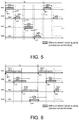
- the total number N of control channels is 4 and the number n of control channels simultaneously outputting the conduction control signals is 1, as described above.
- a delay time between control channels is ⁇ b and a control period is Ts.
- the electrification quantity according to calculation for feedback control is equal to or greater than the upper limit values in the control channels CH1 and CH3. Accordingly, effective electrification quantities td11 and td13 are set by the upper limit values td1m and td3m in the control channels CH1 and CH3. On the other hand, the electrification quantity according to calculation for feedback control is less than the upper limit values in the control channels CH2 and CH4. Accordingly, effective electrification quantities td12 and td14 are set by the electrification quantities according to calculation for feedback control in the control channels CH2 and CH4.
- conduction control is realized with the effective electrification quantity td11 from a time t11 having a delay time tD1 (substantially "0") with respect to a starting timing of the effective control period Te in the control channel CH1.
- Conduction control is realized with the effective electrification quantity td12 from a time t12 having a delay time tD2 with respect to the starting timing of the effective control period Te in the control channel CH2.
- Conduction control is realized with the effective electrification quantity td13 from a time t13 having a delay time tD3 with respect to the starting timing of the effective control period Te in the control channel CH3.
- Conduction control is realized with the effective electrification quantity td14 from a time t14 having a delay time tD4 with respect to the starting timing of the effective control period Te in the control channel CH4.
- a period of conduction control of the control channel CH1 a period of conduction control of the control channel CH2, a period of conduction control of the control channel CH3 and a period of conduction control of the control channel CH4 do not overlap.
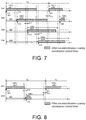
- the total number N of control channels is 4 and the number n of control channels simultaneously outputting conduction control signal is 2, as described above.
- the effective control period Te Ts.
- upper limit values tdlm, td2m, td3m and td4m of electrification quantities for control channels CH1, CH2, CH3 and CH4 are calculated through the above-described method.
- delay times tD1, tD2, tD3 and tD4 in starting of control for the control channels CH1, CH2, CH3 and CH4 are calculated through the above-described method.
- the electrification quantity according to calculation for feedback control is equal to or greater than the upper limit values in the control channels CH1 and CH3. Accordingly, effective electrification quantities td11 and td13 are set by the upper limit values td1m and td3m in the control channels CH1 and CH3. On the other hand, the electrification quantity according to calculation for feedback control is less than the upper limit values in the control channels CH2 and CH4. Accordingly, effective electrification quantities td12 and td14 are set by the electrification quantities according to calculation for feedback control in the control channels CH2 and CH4.
- conduction control is realized with the effective electrification quantity td11 from a time t11 having a delay time tD1 (substantially "0") with respect to a starting timing of the effective control period Te in the control channel CH1.
- Conduction control is realized with the effective electrification quantity td12 from a time t12 having a delay time tD2 with respect to the starting timing of the effective control period Te in the control channel CH2.
- Conduction control is realized with the effective electrification quantity td13 from a time t13 having a delay time tD3 with respect to the starting timing of the effective control period Te in the control channel CH3.
- Conduction control is realized with the effective electrification quantity td14 from a time t14 having a delay time tD4 with respect to the starting timing of the effective control period Te in the control channel CH4.
- a period in which a period of conduction control of the control channel CH1 and a period of conduction control of the control channel CH2 overlap may be present.
- a period in which the period of conduction control of the control channel CH1 and a period of conduction control of the control channel CH3 overlap is not present.
- a period in which the period of conduction control of the control channel CH2 and the period of conduction control of the control channel CH3 overlap may be present.
- a period in which the period of conduction control of the control channel CH2 and a period of conduction control of the control channel CH4 overlap is not present.
- a period in which the period of conduction control of the control channel CH3 and the period of conduction control of the control channel CH4 overlap may be present.
- a period in which the period of conduction control of the control channel CH3 and a period of conduction control of the control channel CH1 of the next effective control period overlap is not present.
- a period in which the period of conduction control of the control channel CH4 and the period of conduction control of the control channel CH1 of the next effective control period overlap may be present.
- a period in which the period of conduction control of the control channel CH4 and a period of conduction control of the control channel CH2 of the next effective control period overlap is not present.
- the total number N of control channels is 4 and the number n of control channels simultaneously outputting conduction control signal is 3, as described above.
- a delay time between control channels is ⁇ b and a control period is Ts.
- the effective control period Te Ts+4 ⁇ b.
- upper limit values tdlm, td2m, td3m and td4m of electrification quantities for control channels CH1, CH2, CH3 and CH4 are calculated through the above-described method.
- delay times tD1, tD2, tD3 and tD4 in starting of control for the control channels CH1, CH2, CH3 and CH4 are calculated through the above-described method.
- the electrification quantity according to calculation for feedback control is equal to or greater than the upper limit values in the control channels CH1 and CH2. Accordingly, effective electrification quantities td11 and td12 are set by the upper limit values td1m and td2m in the control channels CH1 and CH2. On the other hand, the electrification quantity according to calculation for feedback control is less than the upper limit values in the control channels CH3 and CH4. Accordingly, effective electrification quantities td13 and td14 are set by the electrification quantities according to calculation for feedback control in the control channels CH3 and CH4.
- conduction control is realized with the effective electrification quantity td11 from a time t11 having a delay time tD1 (substantially "0") with respect to a starting timing of the effective control period Te in the control channel CH1.
- Conduction control is realized with the effective electrification quantity td12 from a time t12 having a delay time tD2 with respect to the starting timing of the effective control period Te in the control channel CH2.
- Conduction control is realized with the effective electrification quantity td13 from a time t13 having a delay time tD3 with respect to the starting timing of the effective control period Te in the control channel CH3.
- Conduction control is realized with the effective electrification quantity td14 from a time t14 having a delay time tD4 with respect to the starting timing of the effective control period Te in the control channel CH4.
- the number of control channels which are simultaneously controlled to be conducted is at most 3 and a period in which the 4 control channels simultaneously overlap and conduction control is performed is not present.
- normal feedback control may be executed when control of setting the number of control channels simultaneously outputting the conduction control signals to 4, that is, simultaneous electrification of all control channels connected to the heating member 30, can be performed.
- the total number N of control channels is 2 and the number n of control channels simultaneously outputting conduction control signal is 1, as described above.
- a delay time between control channels is ⁇ b and a control period is Ts.
- the effective control period Te Ts+2 ⁇ b.
- upper limit values td1m and td2m of electrification quantities for control channels CH1 and CH2 are calculated through the above-described method.
- delay times tD1 and tD2 in starting of control for the control channels CH1 and CH2 are calculated through the above-described method.
- the electrification quantity according to calculation for feedback control is equal to or greater than the upper limit value in the control channel CH1. Accordingly, the effective electrification quantity td11 is set by the upper limit value td1m in the control channel CH1. On the other hand, the electrification quantity according to calculation for feedback control is less than the upper limit value in the control channel CH2. Accordingly, the effective electrification quantity td12 is set by the electrification quantity according to calculation for feedback control in the control channel CH2.
- conduction control is realized with the effective electrification quantity td11 from a time t11 having a delay time tD1 (substantially "0") with respect to a starting timing of the effective control period Te in the control channel CH1.
- Conduction control is realized with the effective electrification quantity td12 from a time t12 having a delay time tD2 with respect to the starting timing of the effective control period Te in the control channel CH2.
- a period of conduction control of the control channel CH1 and a period of conduction control of the control channel CH2 do not overlap.
- temperature control has been represented in the above description, the present disclosure is not limited to temperature control as long as a system which performs control of conduction and disconnection is adopted.
Landscapes
- Engineering & Computer Science (AREA)
- Chemical & Material Sciences (AREA)
- Combustion & Propulsion (AREA)
- Mechanical Engineering (AREA)
- General Engineering & Computer Science (AREA)
- Supply And Distribution Of Alternating Current (AREA)
- Control Of Electrical Variables (AREA)
Abstract
Description
- The present disclosure relates to a technology of electrification control for loads such as heaters.
-
Patent Document 1 discloses a power control apparatus which controls electrifying time for a plurality of heaters. The power control apparatus includes a power control calculation part and a plurality of switch elements. - The plurality of switches are provided to correspond to the plurality of heaters one-to-one. The power control calculation part sets an individual control channel for each of the plurality of switch elements. The power control calculation part controls opening and closing of each of the plurality of switch elements using the control channel. In this manner, an electrifying time, that is, an electrification quantity, of each of the plurality of heaters is controlled.
- [Patent Document 1]
JP 4407616 - In such a power control system, limitation of an electrification quantity for a load may be desired. For example, there are cases in which an overall peak current including a plurality of loads (e.g., heaters) is desired to be limited and the like. In such cases, switch elements which are simultaneously closed are limited. That is, the number of control channels which simultaneously output conduction control signals is limited.
- However, in the conventional power control apparatus, it is difficult to arbitrarily vary control channels which simultaneously output conduction control signals with respect to the total number of control channels.
- Accordingly, an objective of the present disclosure is to provide an electrification technology capable of performing appropriate electrification control in response to the number of control channels which simultaneously output conduction control signals.
- According to an example of the present disclosure, a power control device includes a setting part, a calculation part, and a control part. The setting part receives a setting of the number of control channels simultaneously controlled to be conducted, and a setting of a control period. The calculation part calculates an upper limit value of an electrification quantity for each control channel and a delay time in starting of control of each control channel using a total number of control channels, the number of control channels simultaneously outputting conduction control signals, and the control period. The control part executes conduction control and disconnection control for each control channel using the upper limit value of the electrification quantity of each control channel and the delay time in starting of control of each control channel.
- In this configuration, if the number of control channels simultaneously outputting the conduction control signals and the control period are input, time of conduction control of each control channel is automatically calculated. Accordingly, conduction control and disconnection control of each control channel according to limitations on electrification quantities of loads are realized.
- In addition, according to an example of the present disclosure, the setting part receives setting of a delay time between control channels. The calculation part calculates an effective control period using a maximum number of available control channels, the delay time between control channels and the control period. The calculation part calculates the upper limit value of the electrification quantity of each control channel and the delay time in starting of control of each control channel on the basis of the effective control period.
- In this configuration, time of conduction control of each control channel is automatically calculated taking into account the delay time between control channels. Accordingly, it is possible to restrain electrification quantities from exceeding limitation of electrification quantities of loads more reliably.
- In addition, according to an example of the present disclosure, the calculation part acquires an electrification quantity according to calculation for feedback control for each control channel. The calculation part sets an effective electrification quantity of a control channel using the electrification quantity according to calculation for feedback control and the upper limit value of the electrification quantity.
- In this configuration, it is possible to perform conduction control and disconnection control adapted to measured values of a plurality of loads while restraining electrification quantities from exceeding limitations of electrification quantities of loads.
- According to the present disclosure, it is possible to perform appropriate control in response to the number of control channels for simultaneous conduction.
-
-
FIG. 1 is a functional block diagram showing an example of a power control system and a power control device according to an embodiment of the present disclosure. -
FIG. 2 is a flowchart showing an example of a power control method according to an embodiment of the present disclosure. -
FIG. 3 is a flowchart showing an example of a setting process and a calculation process in the power control method according to an embodiment of the present disclosure. -
FIG. 4 is a flowchart showing an example of a calculation process in the power control method according to an embodiment of the present disclosure. -
FIG. 5 is a timing chart showing an example of a first aspect of electrification control according to an embodiment of the present disclosure. -
FIG. 6 is a timing chart showing an example of a second aspect of electrification control according to an embodiment of the present disclosure. -
FIG. 7 is a timing chart showing an example of a third aspect of electrification control according to an embodiment of the present disclosure. -
FIG. 8 is a timing chart showing an example of a fourth aspect of electrification control according to an embodiment of the present disclosure. - Hereinafter, embodiments of the present disclosure will be described with reference to the drawings.
- First, an example of application of a power control device according to an embodiment of the present disclosure will be described using the drawings.
-
FIG. 1 is a functional block diagram showing an example of a power control system and a power control device according to an embodiment of the present disclosure. - A
power control device 10 includes asetting part 11, acalculation part 12 and acontrol part 13. Thesetting part 11 receives settings of a control period Ts and the number n of control channels which simultaneously output conduction control signals. - The
calculation part 12 calculates an upper limit value tdm of an electrification quantity within the time of the control period Ts of each control channel, that is, upper limit value of electrification quantities of aswitch element 21, aswitch element 22, aswitch element 23 and aswitch element 24 using the control period Ts, the number n of simultaneously conducted control channels and a total number N of control channels controlled by thepower control device 10 in apower control system 1. In addition, thecalculation part 12 calculates a delay time tDN in starting of conduction control of each control channel with respect to a starting time of the control period Ts. - The
control part 13 controls a period of conduction control and a period of disconnection control of each control channel using the upper limit value tdm of the electrification quantities and the delay time tDN. Accordingly, closing and opening of theswitch element 21, theswitch element 22, theswitch element 23 and theswitch element 24 of anSSR 20 are controlled and electrification quantities of aheater 31, aheater 32, aheater 33 and aheater 34 of aheating member 30 are controlled. - In this manner, conduction control and disconnection control of each control channel are automatically executed in response to the number of switch elements (the number of control channels) which are simultaneously controlled to be closed. Accordingly, it is possible to perform appropriate control according to a limitation of the electrification quantity of the
heating member 30. - The power control device, the power control system, a power control method and a power control program according to an embodiment of the present disclosure will be described with reference to the drawings. As described above,
FIG. 1 is a functional block diagram showing an example of the power control system and the power control device according to an embodiment of the present disclosure. Meanwhile, although a case in which the total number N of control channels, the number of switch elements and the number of heaters are 4 will be represented in the following description, the total number N of control channels, the number of switch elements and the number of heaters are not limited thereto as long as they are plural in number. - The
power control system 1 includes thepower control device 10, the SSR 20, theheating member 30, apower source 40, and asensor 50. Thepower control device 10 includes thesetting part 11, thecalculation part 12 and thecontrol part 13. - The SSR 20 includes the
switch element 21, theswitch element 22, theswitch element 23 and theswitch element 24. Theheating member 30 includes theheater 31, theheater 32, theheater 33 and theheater 34. - The
switch element 21 and theheater 31 are serially connected to constitute a first serial circuit. Theswitch element 22 and theheater 32 are serially connected to constitute a second serial circuit. Theswitch element 23 and theheater 33 are serially connected to constitute a third serial circuit. Theswitch element 24 and theheater 34 are serially connected to constitute a fourth serial circuit. The first serial circuit, the second serial circuit, the third serial circuit and the fourth serial circuit are connected parallel to thepower source 40. - The
switch element 21, theswitch element 22, theswitch element 23 and theswitch element 24 are connected to thecontrol part 13. Theswitch element 21 is closed or opened by receiving a control signal of a control channel CH1 from thecontrol part 13. Accordingly, conduction or disconnection of theheater 31 and thepower source 40 is controlled and an electrification quantity to theheater 31 is controlled. Theswitch element 22 is closed or opened by receiving a control signal of a control channel CH2 from thecontrol part 13. Accordingly, conduction or disconnection of theheater 32 and thepower source 40 is controlled and an electrification quantity to theheater 32 is controlled. Theswitch element 23 is closed or opened by receiving a control signal of a control channel CH3 from thecontrol part 13. Accordingly, conduction or disconnection of theheater 33 and thepower source 40 is controlled and an electrification quantity to theheater 33 is controlled. Theswitch element 24 is closed or opened by receiving a control signal of a control channel CH4 from thecontrol part 13. Accordingly, conduction or disconnection of theheater 34 and thepower source 40 is controlled and an electrification quantity to theheater 34 is controlled. These electrification quantities are set by conduction time, that is, time durations of the control signals for closing the switch elements. - The
sensor 50 measures a temperature and the like of a heating target of theheating member 30 and outputs measurement data to thecalculation part 12. - In this
power control system 1, thepower control device 10 includes the following configuration and executes the following control. - For example, the setting
part 11 includes operators such as a mouse, a keyboard and a touch panel. The settingpart 11 receives an operation input from a user and outputs the operation input to thecalculation part 12. Specifically, the settingpart 11 receives settings of the total number N of control channels, a control period Ts, and the number n of control channels simultaneously outputting conduction control signals from the user. Further, the total number N of control channels is not the total number of control channels included in thepower control device 10 but is the total number of control channels connected to theheating member 30. Further, the settingpart 11 receives setting of a delay time τb between control channels from the user. - The setting
part 11 outputs the total number N of control channels, the control period Ts, the number n of control channels simultaneously outputting conduction control signals and the delay time τb between control channels to thecalculation part 12. - For example, the
calculation part 12 is realized by an information processing IC and a program installed in the IC. - The
calculation part 12 calculates an effective control period Te using the total number N of control channels, the control period Ts, and the delay time τb between control channels. Specifically, thecalculation part 12 calculates the effective control period Te as Te=Ts+(τb×N). - The
calculation part 12 calculates upper limit value tdm of electrification quantities in the effective control period Te using the total number N of control channels and the number n of control channels simultaneously outputting conduction control signals. The upper limit value tdm of electrification quantities is set according to time (conduction time). Specifically, thecalculation part 12 calculates the upper limit value tdm of electrification quantities as tdm=n/N. Further, thecalculation part 12 calculates an upper limit value tdMm of an electrification quantity of each control channel M by dividing the upper limit value tdm of all electrification quantities by the number n of control channels simultaneously outputting the conduction control signals. - The
calculation part 12 calculates a delay time tD in starting of control for each control channel using the effective control period Te and the total number N of control channels. Specifically, starting of control in order from a control channel having a smaller number in the effective control period Te is set, and thecalculation part 12 calculates a delay time tDM in starting of control of a control channel M as tDM=Te/(N×(M-1)). - In addition, the
calculation part 12 performs calculation for feedback control of bringing a measured value (measured temperature) from thesensor 50 close to a target value (target temperature) using the measured value and calculates an electrification quantity of each control channel M in the next effective control period Te. For example, thecalculation part 12 may employ PID control as feedback control. Meanwhile, a feedback control type is not limited to PID control. - The
calculation part 12 compares the upper limit value tdMm of the electrification quantity of the control channel M with an electrification quantity obtained through calculation for feedback control of the control channel M. If the electrification quantity obtained through calculation for feedback control is equal to or less than the upper limit value tdMm of the electrification quantity, thecalculation part 12 sets the electrification quantity obtained through calculation for feedback control to an effective electrification quantity td. If the electrification quantity obtained through calculation for feedback control is greater than the upper limit value tdMm of the electrification quantity, thecalculation part 12 sets the upper limit value tdMm of the electrification quantity to the effective electrification quantity td. - The
calculation part 12 outputs the effective control period Te, the effective electrification quantity (effective conduction time) td, and the delay time tDM in starting of control of the control channel M to thecontrol part 13. - For example, the
control part 13 is realized by an information processing IC having a timer function and a program installed in this IC. Meanwhile, thecontrol part 13 may be formed using the IC same as thecalculation part 12. - The
control part 13 determines a conduction control signal output period for each control channel using the effective control period Te, the effective electrification quantity (effective conduction time) td, and the delay time tDM in starting of control of the control channel M. That is, thecontrol part 13 executes conduction control and disconnection control for each control channel using the effective control period Te, the effective electrification quantity (effective conduction time) td, and the delay time tDM in starting of control of the control channel M. - It is possible to appropriately set the number of control channels simultaneously outputting the conduction control signals using the aforementioned configuration and process. In addition, it is possible to realize electrification control in response to the number of control channels simultaneously outputting the conduction control signals. Accordingly, it is possible to realize electrification control without exceeding the set upper limit value of electrification quantities.
- Furthermore, it is possible to prevent the effective electrification quantity from excessively decreasing. Accordingly, it is possible to restrain occurrence of adverse effects such as unwanted delay of arrival at a target value and to realize appropriate electrification control according to feedback control.
- Meanwhile, although an aspect in which the
calculation part 12 and thecontrol part 13 are realized using an IC has been shown in the above description, they may be realized by an information processing CPU, a program executed by the CPU, and an information processing device having a storage means storing the program. In this case, the information processing device may execute the process described below.FIG. 2 is a flowchart showing an example of a power control method according to an embodiment of the present disclosure.FIG. 3 is a flowchart showing an example of a setting process and a calculation process in the power control method according to an embodiment of the present disclosure.FIG. 4 is a flowchart showing an example of a calculation process in the power control method according to an embodiment of the present disclosure. - The information processing device executes the process shown in
FIG. 2 as a schematic process. First, the information processing device sets control conditions (S11). Specifically, the information processing device calculates the effective control period Te using the total number N of control channels, the control period Ts and the delay time τb between control channels. In addition, the information processing device calculates the upper limit value tdm of electrification quantities in the effective control period Te using the total number N of control channels, and the number n of control channels simultaneously outputting the conduction control signals. Then, the information processing device calculates the upper limit value tdMm of an electrification quantity of each control channel M by dividing the upper limit value tdm of all electrification quantities by the number n of control channels simultaneously outputting the conduction control signals. - In addition, the information processing device calculates a delay time tD in starting of control for each control channel using the effective control period Te and the total number N of control channels. Further, the information processing device performs calculation for feedback control of bringing a measured value (measured temperature) from the
sensor 50 close to a target value (target temperature) using the measured value and calculates an electrification quantity of each control channel M in the next effective control period Te. - Subsequently, the information processing device calculates an electrification quantity (effective electrification quantity td) for each control channel M (S12). Specifically, the information processing device compares the upper limit value tdMm of the electrification quantity of the control channel M with an electrification quantity obtained through the calculation of feedback control and calculates the electrification quantity (effective electrification quantity td) of each control channel, as described above.
- Then, the information processing device executes control of conduction for each control channel M using the aforementioned control conditions and the electrification quantity (effective electrification quantity td) of each control channel M (S13).
- For example, setting of the control conditions in step S11 is performed through the process shown in
FIG. 3 , for example. - First, the information processing device receives the total number N of control channels (S101). The information processing device receives the control period Ts (S102). The information processing device receives the number n of control channels simultaneously outputting the conduction control signals (S103). The information processing device receives the delay time τb between control channels (S104). Meanwhile, the order of execution of steps S101, S102, S103 and S104 by the information processing device is not limited to the aforementioned order.
- Thereafter, the information processing device calculates the effective control period Te using the above-described method (S105).
- Subsequently, the information processing device calculates the starting delay time tD for each control channel using the above-described method (S106). The information processing device calculates the upper limit value tdm of electrification quantities using the above-described method (S107). Meanwhile, the order of execution of steps S106 and S107 by the information processing device is not limited to the aforementioned order.
- For example, calculation of the electrification quantity for each control channel in step S12 is executed through the process shown in
FIG. 4 . - The information processing device calculates an electrification quantity tdc according to calculation for feedback control (S201). The information processing device compares the electrification quantity tdc according to calculation for feedback control with the upper limit value tdMm of the electrification quantity of the control channel M. The information processing device sets the electrification quantity tdc as the effective electrification quantity td (S203) if the electrification quantity tdc is equal to or less than the upper limit value tdMm (S202: YES). The information processing device sets the upper limit value tdMm as the effective electrification quantity td (S203) if the electrification quantity tdc is greater than the upper limit value tdMm (S202: NO).
- Next, specific aspects of control will be described using timing charts.
- (1) Case in which the total number N of control channels is 4 (N=4) and the number n of control channels simultaneously outputting conduction control signal is 1 (n=1)
FIG. 5 is a timing chart showing an example of a first aspect of electrification control according to an embodiment of the present disclosure. - In the aspect shown in
FIG. 5 , the total number N of control channels is 4 and the number n of control channels simultaneously outputting the conduction control signals is 1, as described above. In addition, a delay time between control channels is τb and a control period is Ts. - In this case, the effective control period Te=Ts+4τb. Further, upper limit values tdlm, td2m, td3m and td4m of electrification quantities for control channels CH1, CH2, CH3 and CH4 are calculated through the above-described method. In addition, delay times tD1, tD2, tD3 and tD4 in starting of control for the control channels CH1, CH2, CH3 and CH4 are calculated through the above-described method.
- Further, in the case of
FIG. 5 , the electrification quantity according to calculation for feedback control is equal to or greater than the upper limit values in the control channels CH1 and CH3. Accordingly, effective electrification quantities td11 and td13 are set by the upper limit values td1m and td3m in the control channels CH1 and CH3. On the other hand, the electrification quantity according to calculation for feedback control is less than the upper limit values in the control channels CH2 and CH4. Accordingly, effective electrification quantities td12 and td14 are set by the electrification quantities according to calculation for feedback control in the control channels CH2 and CH4. - In a state in which the effective electrification quantities have been determined, conduction control is realized with the effective electrification quantity td11 from a time t11 having a delay time tD1 (substantially "0") with respect to a starting timing of the effective control period Te in the control channel CH1. Conduction control is realized with the effective electrification quantity td12 from a time t12 having a delay time tD2 with respect to the starting timing of the effective control period Te in the control channel CH2. Conduction control is realized with the effective electrification quantity td13 from a time t13 having a delay time tD3 with respect to the starting timing of the effective control period Te in the control channel CH3. Conduction control is realized with the effective electrification quantity td14 from a time t14 having a delay time tD4 with respect to the starting timing of the effective control period Te in the control channel CH4.
- When control is performed in this manner, a period of conduction control of the control channel CH1, a period of conduction control of the control channel CH2, a period of conduction control of the control channel CH3 and a period of conduction control of the control channel CH4 do not overlap.
- Accordingly, in a configuration in which the total number of control channels is 4, it is possible to reliably perform control of setting the number of control channels simultaneously outputting the conduction control signals to 1, that is, control in which upper limit values of electrification quantities have been designated according to such conduction control. In addition, it is possible to reliably realize feedback control for each control channel.
- (2) Case in which the total number N of control channels is 4 (N=4) and the number n of control channels simultaneously outputting conduction control signal is 2 (n=2)
FIG. 6 is a timing chart showing an example of a second aspect of electrification control according to an embodiment of the present disclosure. - In the aspect shown in
FIG. 6 , the total number N of control channels is 4 and the number n of control channels simultaneously outputting conduction control signal is 2, as described above. In addition, a delay time between control channels is τb=0 and a control period is Ts. - In this case, the effective control period Te=Ts. Further, upper limit values tdlm, td2m, td3m and td4m of electrification quantities for control channels CH1, CH2, CH3 and CH4 are calculated through the above-described method. In addition, delay times tD1, tD2, tD3 and tD4 in starting of control for the control channels CH1, CH2, CH3 and CH4 are calculated through the above-described method.
- Further, in the case of
FIG. 6 , the electrification quantity according to calculation for feedback control is equal to or greater than the upper limit values in the control channels CH1 and CH3. Accordingly, effective electrification quantities td11 and td13 are set by the upper limit values td1m and td3m in the control channels CH1 and CH3. On the other hand, the electrification quantity according to calculation for feedback control is less than the upper limit values in the control channels CH2 and CH4. Accordingly, effective electrification quantities td12 and td14 are set by the electrification quantities according to calculation for feedback control in the control channels CH2 and CH4. - In a state in which the effective electrification quantities have been determined, conduction control is realized with the effective electrification quantity td11 from a time t11 having a delay time tD1 (substantially "0") with respect to a starting timing of the effective control period Te in the control channel CH1. Conduction control is realized with the effective electrification quantity td12 from a time t12 having a delay time tD2 with respect to the starting timing of the effective control period Te in the control channel CH2. Conduction control is realized with the effective electrification quantity td13 from a time t13 having a delay time tD3 with respect to the starting timing of the effective control period Te in the control channel CH3. Conduction control is realized with the effective electrification quantity td14 from a time t14 having a delay time tD4 with respect to the starting timing of the effective control period Te in the control channel CH4.
- When such a control is performed, a period in which a period of conduction control of the control channel CH1 and a period of conduction control of the control channel CH2 overlap may be present. On the other hand, a period in which the period of conduction control of the control channel CH1 and a period of conduction control of the control channel CH3 overlap is not present.
- Further, a period in which the period of conduction control of the control channel CH2 and the period of conduction control of the control channel CH3 overlap may be present. On the other hand, a period in which the period of conduction control of the control channel CH2 and a period of conduction control of the control channel CH4 overlap is not present.
- In addition, a period in which the period of conduction control of the control channel CH3 and the period of conduction control of the control channel CH4 overlap may be present. On the other hand, a period in which the period of conduction control of the control channel CH3 and a period of conduction control of the control channel CH1 of the next effective control period overlap is not present.
- Further, a period in which the period of conduction control of the control channel CH4 and the period of conduction control of the control channel CH1 of the next effective control period overlap may be present. On the other hand, a period in which the period of conduction control of the control channel CH4 and a period of conduction control of the control channel CH2 of the next effective control period overlap is not present.
- In this manner, a period in which three or more control channels overlap and conduction control is performed is not present when performing this control.
- Accordingly, in a configuration in which the total number of control channels is 4, it is possible to reliably perform control of setting the number of control channels simultaneously outputting the conduction control signals to 2, that is, control in which upper limit values of electrification quantities have been designated according to such conduction control. In addition, it is possible to reliably realize feedback control for each control channel.
- (3) Case in which the total number N of control channels is 4 (N=4) and the number n of control channels simultaneously outputting conduction control signal is 3 (n=3)
FIG. 7 is a timing chart showing an example of a third aspect of electrification control according to an embodiment of the present disclosure. - In the aspect shown in
FIG. 7 , the total number N of control channels is 4 and the number n of control channels simultaneously outputting conduction control signal is 3, as described above. In addition, a delay time between control channels is τb and a control period is Ts. - In this case, the effective control period Te=Ts+4τb. Further, upper limit values tdlm, td2m, td3m and td4m of electrification quantities for control channels CH1, CH2, CH3 and CH4 are calculated through the above-described method. In addition, delay times tD1, tD2, tD3 and tD4 in starting of control for the control channels CH1, CH2, CH3 and CH4 are calculated through the above-described method.
- Further, in the case of
FIG. 7 , the electrification quantity according to calculation for feedback control is equal to or greater than the upper limit values in the control channels CH1 and CH2. Accordingly, effective electrification quantities td11 and td12 are set by the upper limit values td1m and td2m in the control channels CH1 and CH2. On the other hand, the electrification quantity according to calculation for feedback control is less than the upper limit values in the control channels CH3 and CH4. Accordingly, effective electrification quantities td13 and td14 are set by the electrification quantities according to calculation for feedback control in the control channels CH3 and CH4. - In a state in which the effective electrification quantities have been determined, conduction control is realized with the effective electrification quantity td11 from a time t11 having a delay time tD1 (substantially "0") with respect to a starting timing of the effective control period Te in the control channel CH1. Conduction control is realized with the effective electrification quantity td12 from a time t12 having a delay time tD2 with respect to the starting timing of the effective control period Te in the control channel CH2. Conduction control is realized with the effective electrification quantity td13 from a time t13 having a delay time tD3 with respect to the starting timing of the effective control period Te in the control channel CH3. Conduction control is realized with the effective electrification quantity td14 from a time t14 having a delay time tD4 with respect to the starting timing of the effective control period Te in the control channel CH4.
- When control is performed in this manner, the number of control channels which are simultaneously controlled to be conducted is at most 3 and a period in which the 4 control channels simultaneously overlap and conduction control is performed is not present.
- Accordingly, in a configuration in which the total number of control channels is 4, it is possible to reliably perform control of setting the number of control channels simultaneously outputting the conduction control signals to 3, that is, control in which upper limit values of electrification quantities have been designated according to such conduction control. In addition, it is possible to reliably realize feedback control for each control channel.
- Meanwhile, in a configuration in which the total number of control channels is 4, normal feedback control may be executed when control of setting the number of control channels simultaneously outputting the conduction control signals to 4, that is, simultaneous electrification of all control channels connected to the
heating member 30, can be performed. - (4) Case in which the total number N of control channels is 2 (N=2) and the number n of control channels simultaneously outputting conduction control signal is 1 (n=1)
FIG. 8 is a timing chart showing an example of a fourth aspect of electrification control according to an embodiment of the present disclosure. - In the aspect shown in
FIG. 8 , the total number N of control channels is 2 and the number n of control channels simultaneously outputting conduction control signal is 1, as described above. In addition, a delay time between control channels is τb and a control period is Ts. - In this case, the effective control period Te=Ts+2τb. Further, upper limit values td1m and td2m of electrification quantities for control channels CH1 and CH2 are calculated through the above-described method. In addition, delay times tD1 and tD2 in starting of control for the control channels CH1 and CH2 are calculated through the above-described method.
- Further, in the case of
FIG. 8 , the electrification quantity according to calculation for feedback control is equal to or greater than the upper limit value in the control channel CH1. Accordingly, the effective electrification quantity td11 is set by the upper limit value td1m in the control channel CH1. On the other hand, the electrification quantity according to calculation for feedback control is less than the upper limit value in the control channel CH2. Accordingly, the effective electrification quantity td12 is set by the electrification quantity according to calculation for feedback control in the control channel CH2. - In a state in which the effective electrification quantities have been determined, conduction control is realized with the effective electrification quantity td11 from a time t11 having a delay time tD1 (substantially "0") with respect to a starting timing of the effective control period Te in the control channel CH1. Conduction control is realized with the effective electrification quantity td12 from a time t12 having a delay time tD2 with respect to the starting timing of the effective control period Te in the control channel CH2.
- When such a control is performed, a period of conduction control of the control channel CH1 and a period of conduction control of the control channel CH2 do not overlap.
- Accordingly, in a configuration in which the total number of control channels is set to 2, it is possible to reliably perform control of setting the number of control channels simultaneously outputting the conduction control signals to 1, that is, control in which upper limit values of electrification quantities is designated according to such conduction control. In addition, it is possible to reliably realize feedback control for each control channel.
- Meanwhile, it is effective to execute the above-described process when feedback control is performed, and the process may not be executed when feedback control is not performed.
- Furthermore, although a case of temperature control has been represented in the above description, the present disclosure is not limited to temperature control as long as a system which performs control of conduction and disconnection is adopted.
-
- 1
- Power control system
- 10
- Power control device
- 11
- Setting part
- 12
- Calculation part
- 13
- Control part
- 20
- SSR
- 21, 22, 23, 24
- Switch element
- 30
- Heating member
- 31, 32, 33, 34
- Heater
- 40
- Power source
- 50
- Sensor
Claims (9)
- A power control device (10), characterized in that the power control device (10) comprises:a setting part (11) which receives a setting of the number of control channels (CH1, CH2, CH3, CH4) simultaneously outputting conduction control signals and a setting of a control period (Ts);a calculation part (12) which calculates an upper limit value (tdMm) of an electrification quantity for each control channel and a delay time (tDM) in starting of control of each control channel using a total number of control channels (CH1, CH2, CH3, CH4), the number of control channels (CH1, CH2, CH3, CH4) simultaneously outputting the conduction control signals, and the control period (Ts); anda control part (13) which executes conduction control and disconnection control for each control channel using the upper limit value (tdMm) of the electrification quantity of each control channel and the delay time (tDM) in starting of control of each control channel.
- The power control device (10) according to claim 1, wherein the setting part (11) receives setting of a delay time (τb) between control channels (CH1, CH2, CH3, CH4), and the calculation part (12) calculates an effective control period (Te) using the total number of control channels (CH1, CH2, CH3, CH4), the delay time (τb) between control channels (CH1, CH2, CH3, CH4) and the control period (Ts) and calculates the upper limit value (tdMm) of the electrification quantity for each control channel and the delay time (tDM) in starting of control of each control channel on the basis of the effective control period (Te).
- The power control device (10) according to claim 1 or 2, wherein the calculation part (12) calculates a conduction time according to calculation for feedback control for each control channel and sets an effective electrification quantity of the control channel using an electrification quantity according to the calculation for feedback control and the upper limit value (tdMm) of the electrification quantity.
- The power control device (10) according to claim 3, wherein the calculation part (12) sets the effective electrification quantity of the control channel to the electrification quantity according to the calculation for feedback control if the electrification quantity according to the calculation for feedback control is equal to or less than the upper limit value (tdMm) of the electrification quantity.
- The power control device (10) according to claim 3 or 4, wherein the calculation part (12) sets the effective electrification quantity of the control channel to the upper limit value (tdMm) of the electrification quantity if the electrification quantity according to the calculation for feedback control is equal to or greater than the upper limit value (tdMm) of the electrification quantity.
- A power control system (1), characterized in that the power control system (1) comprises:the power control device (10) according to any one of claims 1 to 5;a plurality of loads (31, 32, 33, 34) controlled to be electrified;a power source (40) which supplies power to the plurality of loads (31, 32, 33, 34); anda plurality of switch elements (21, 22, 23, 24) which conduct or disconnect the power source and each of the plurality of loads (31, 32, 33, 34), the plurality of switch elements (21, 22, 23, 24) are controlled by the plurality of control channels (CH1, CH2, CH3, CH4).
- The power control system (1) according to claim 6, comprising a sensor (50) which measures states of the loads (31, 32, 33, 34) and feeds back the states to the calculation part (12).
- A power control method, characterized in that the power control method comprises:receiving a setting of a number of control channels (CH1, CH2, CH3, CH4) simultaneously outputting conduction control signals and a setting of a control period (Ts);calculating an upper limit value (tdMm) of an electrification quantity of each control channel and a delay time (tDM) in starting of control of each control channel using a maximum number of available control channels (CH1, CH2, CH3, CH4), the number of control channels (CH1, CH2, CH3, CH4) simultaneously outputting the conduction control signals, and the control period (Ts); andexecuting conduction control and disconnection control for each control channel using the upper limit value (tdMm) of the electrification quantity for each control channel and the delay time (tDM) in starting of control for each control channel.
- A power control program, characterized in that the power control program causes an information processing device to execute:a process of receiving a setting of a number of control channels (CH1, CH2, CH3, CH4) simultaneously outputting conduction control signals and a setting of a control period (Ts);a process of calculating an upper limit value (tdMm) of an electrification quantity of each control channel and a delay time (tDM) in starting of control of each control channel using a total number of control channels (CH1, CH2, CH3, CH4), the number of control channels (CH1, CH2, CH3, CH4) simultaneously outputting the conduction control signals, and the control period (Ts); anda process of executing conduction control and disconnection control for each control channel using the upper limit value (tdMm) of the electrification quantity of each control channel and the delay time (tDM) in starting of control of each control channel.
Applications Claiming Priority (1)
| Application Number | Priority Date | Filing Date | Title |
|---|---|---|---|
| JP2017236094A JP6844519B2 (en) | 2017-12-08 | 2017-12-08 | Power control devices, power control systems, power control methods, and power control programs |
Publications (2)
| Publication Number | Publication Date |
|---|---|
| EP3495648A1 true EP3495648A1 (en) | 2019-06-12 |
| EP3495648B1 EP3495648B1 (en) | 2021-01-13 |
Family
ID=63592607
Family Applications (1)
| Application Number | Title | Priority Date | Filing Date |
|---|---|---|---|
| EP18194533.8A Active EP3495648B1 (en) | 2017-12-08 | 2018-09-14 | Power control device, power control system, power control method, and power control program |
Country Status (2)
| Country | Link |
|---|---|
| EP (1) | EP3495648B1 (en) |
| JP (1) | JP6844519B2 (en) |
Citations (3)
| Publication number | Priority date | Publication date | Assignee | Title |
|---|---|---|---|---|
| US20040099653A1 (en) * | 2000-12-12 | 2004-05-27 | Hirofumi Hirayama | State controller |
| JP4407616B2 (en) | 2005-10-20 | 2010-02-03 | オムロン株式会社 | Power control method, power control device, and temperature controller |
| JP4529153B1 (en) * | 2009-11-27 | 2010-08-25 | 理化工業株式会社 | Multi-channel power controller |
-
2017
- 2017-12-08 JP JP2017236094A patent/JP6844519B2/en active Active
-
2018
- 2018-09-14 EP EP18194533.8A patent/EP3495648B1/en active Active
Patent Citations (3)
| Publication number | Priority date | Publication date | Assignee | Title |
|---|---|---|---|---|
| US20040099653A1 (en) * | 2000-12-12 | 2004-05-27 | Hirofumi Hirayama | State controller |
| JP4407616B2 (en) | 2005-10-20 | 2010-02-03 | オムロン株式会社 | Power control method, power control device, and temperature controller |
| JP4529153B1 (en) * | 2009-11-27 | 2010-08-25 | 理化工業株式会社 | Multi-channel power controller |
Also Published As
| Publication number | Publication date |
|---|---|
| JP6844519B2 (en) | 2021-03-17 |
| EP3495648B1 (en) | 2021-01-13 |
| JP2019106743A (en) | 2019-06-27 |
Similar Documents
| Publication | Publication Date | Title |
|---|---|---|
| JP6413965B2 (en) | Semiconductor device | |
| US20160003921A1 (en) | Method for testing multiple spatially distributed protective devices of an energy supply network, and corresponding testing system | |
| Bastidas-Rodríguez et al. | General modeling procedure for photovoltaic arrays | |
| CN102818940B (en) | Method for detecting with a high temporal accuracy a threshold crossing instant by a signal | |
| KR101738282B1 (en) | Adjustment device, control method, and control program | |
| EP2472711A2 (en) | Commutation control for a power converter and corresponding method | |
| EP3224934B1 (en) | Method and device for controlling power semiconductor switches connected in parallel | |
| CN109036964A (en) | Control method, storage medium, control device and the relay that contact prevents adhesion | |
| DE102014224172A1 (en) | Method and device for driving parallel-connected power semiconductor switches | |
| JP5885977B2 (en) | PWM signal output circuit, PWM signal output control method, and program | |
| EP3495648B1 (en) | Power control device, power control system, power control method, and power control program | |
| US11418018B2 (en) | Arc detection circuit, switch system, power conditioner system and arc detection method | |
| MX2023003507A (en) | Electric power control system, and program. | |
| CN116364473A (en) | Calibration method, device, electronic equipment and storage medium for relay contact control | |
| US10128680B2 (en) | Constant current charging device | |
| EP2821799B1 (en) | Highly accurate current measurement | |
| US20230252213A1 (en) | Method and apparatus for analog simulation of circuit model, computer device, and storage medium | |
| CN111952089B (en) | System and method for controlled switching of a circuit breaker and circuit breaker | |
| EP3506027A1 (en) | Control system, control method, and control program | |
| US20140225431A1 (en) | Apparatus for and method of pulsed control of load elements in motor vehicles | |
| CN105204325A (en) | Timing method and circuit | |
| CN110767502B (en) | Method, controller and system for regulating current to a coil | |
| US9584009B2 (en) | Line current reference generator | |
| CN116931626A (en) | Temperature control system and control method of intelligent closestool | |
| JP2007185078A (en) | Method and device for controlling charge/discharge for battery pack |
Legal Events
| Date | Code | Title | Description |
|---|---|---|---|
| PUAI | Public reference made under article 153(3) epc to a published international application that has entered the european phase |
Free format text: ORIGINAL CODE: 0009012 |
|
| STAA | Information on the status of an ep patent application or granted ep patent |
Free format text: STATUS: REQUEST FOR EXAMINATION WAS MADE |
|
| 17P | Request for examination filed |
Effective date: 20180914 |
|
| AK | Designated contracting states |
Kind code of ref document: A1 Designated state(s): AL AT BE BG CH CY CZ DE DK EE ES FI FR GB GR HR HU IE IS IT LI LT LU LV MC MK MT NL NO PL PT RO RS SE SI SK SM TR |
|
| AX | Request for extension of the european patent |
Extension state: BA ME |
|
| RBV | Designated contracting states (corrected) |
Designated state(s): AL AT BE BG CH CY CZ DE DK EE ES FI FR GB GR HR HU IE IS IT LI LT LU LV MC MK MT NL NO PL PT RO RS SE SI SK SM TR |
|
| GRAP | Despatch of communication of intention to grant a patent |
Free format text: ORIGINAL CODE: EPIDOSNIGR1 |
|
| STAA | Information on the status of an ep patent application or granted ep patent |
Free format text: STATUS: GRANT OF PATENT IS INTENDED |
|
| INTG | Intention to grant announced |
Effective date: 20200922 |
|
| GRAS | Grant fee paid |
Free format text: ORIGINAL CODE: EPIDOSNIGR3 |
|
| GRAA | (expected) grant |
Free format text: ORIGINAL CODE: 0009210 |
|
| STAA | Information on the status of an ep patent application or granted ep patent |
Free format text: STATUS: THE PATENT HAS BEEN GRANTED |
|
| AK | Designated contracting states |
Kind code of ref document: B1 Designated state(s): AL AT BE BG CH CY CZ DE DK EE ES FI FR GB GR HR HU IE IS IT LI LT LU LV MC MK MT NL NO PL PT RO RS SE SI SK SM TR |
|
| REG | Reference to a national code |
Ref country code: GB Ref legal event code: FG4D |
|
| REG | Reference to a national code |
Ref country code: CH Ref legal event code: EP |
|
| REG | Reference to a national code |
Ref country code: IE Ref legal event code: FG4D |
|
| REG | Reference to a national code |
Ref country code: DE Ref legal event code: R096 Ref document number: 602018011779 Country of ref document: DE |
|
| REG | Reference to a national code |
Ref country code: AT Ref legal event code: REF Ref document number: 1354733 Country of ref document: AT Kind code of ref document: T Effective date: 20210215 |
|
| REG | Reference to a national code |
Ref country code: AT Ref legal event code: MK05 Ref document number: 1354733 Country of ref document: AT Kind code of ref document: T Effective date: 20210113 |
|
| REG | Reference to a national code |
Ref country code: NL Ref legal event code: MP Effective date: 20210113 |
|
| REG | Reference to a national code |
Ref country code: LT Ref legal event code: MG9D |
|
| PG25 | Lapsed in a contracting state [announced via postgrant information from national office to epo] |
Ref country code: NO Free format text: LAPSE BECAUSE OF FAILURE TO SUBMIT A TRANSLATION OF THE DESCRIPTION OR TO PAY THE FEE WITHIN THE PRESCRIBED TIME-LIMIT Effective date: 20210413 Ref country code: PT Free format text: LAPSE BECAUSE OF FAILURE TO SUBMIT A TRANSLATION OF THE DESCRIPTION OR TO PAY THE FEE WITHIN THE PRESCRIBED TIME-LIMIT Effective date: 20210513 Ref country code: LT Free format text: LAPSE BECAUSE OF FAILURE TO SUBMIT A TRANSLATION OF THE DESCRIPTION OR TO PAY THE FEE WITHIN THE PRESCRIBED TIME-LIMIT Effective date: 20210113 Ref country code: BG Free format text: LAPSE BECAUSE OF FAILURE TO SUBMIT A TRANSLATION OF THE DESCRIPTION OR TO PAY THE FEE WITHIN THE PRESCRIBED TIME-LIMIT Effective date: 20210413 Ref country code: HR Free format text: LAPSE BECAUSE OF FAILURE TO SUBMIT A TRANSLATION OF THE DESCRIPTION OR TO PAY THE FEE WITHIN THE PRESCRIBED TIME-LIMIT Effective date: 20210113 Ref country code: FI Free format text: LAPSE BECAUSE OF FAILURE TO SUBMIT A TRANSLATION OF THE DESCRIPTION OR TO PAY THE FEE WITHIN THE PRESCRIBED TIME-LIMIT Effective date: 20210113 Ref country code: GR Free format text: LAPSE BECAUSE OF FAILURE TO SUBMIT A TRANSLATION OF THE DESCRIPTION OR TO PAY THE FEE WITHIN THE PRESCRIBED TIME-LIMIT Effective date: 20210414 |
|
| PG25 | Lapsed in a contracting state [announced via postgrant information from national office to epo] |
Ref country code: SE Free format text: LAPSE BECAUSE OF FAILURE TO SUBMIT A TRANSLATION OF THE DESCRIPTION OR TO PAY THE FEE WITHIN THE PRESCRIBED TIME-LIMIT Effective date: 20210113 Ref country code: PL Free format text: LAPSE BECAUSE OF FAILURE TO SUBMIT A TRANSLATION OF THE DESCRIPTION OR TO PAY THE FEE WITHIN THE PRESCRIBED TIME-LIMIT Effective date: 20210113 Ref country code: RS Free format text: LAPSE BECAUSE OF FAILURE TO SUBMIT A TRANSLATION OF THE DESCRIPTION OR TO PAY THE FEE WITHIN THE PRESCRIBED TIME-LIMIT Effective date: 20210113 Ref country code: LV Free format text: LAPSE BECAUSE OF FAILURE TO SUBMIT A TRANSLATION OF THE DESCRIPTION OR TO PAY THE FEE WITHIN THE PRESCRIBED TIME-LIMIT Effective date: 20210113 Ref country code: AT Free format text: LAPSE BECAUSE OF FAILURE TO SUBMIT A TRANSLATION OF THE DESCRIPTION OR TO PAY THE FEE WITHIN THE PRESCRIBED TIME-LIMIT Effective date: 20210113 |
|
| PG25 | Lapsed in a contracting state [announced via postgrant information from national office to epo] |
Ref country code: IS Free format text: LAPSE BECAUSE OF FAILURE TO SUBMIT A TRANSLATION OF THE DESCRIPTION OR TO PAY THE FEE WITHIN THE PRESCRIBED TIME-LIMIT Effective date: 20210513 |
|
| REG | Reference to a national code |
Ref country code: DE Ref legal event code: R097 Ref document number: 602018011779 Country of ref document: DE |
|
| PG25 | Lapsed in a contracting state [announced via postgrant information from national office to epo] |
Ref country code: CZ Free format text: LAPSE BECAUSE OF FAILURE TO SUBMIT A TRANSLATION OF THE DESCRIPTION OR TO PAY THE FEE WITHIN THE PRESCRIBED TIME-LIMIT Effective date: 20210113 Ref country code: EE Free format text: LAPSE BECAUSE OF FAILURE TO SUBMIT A TRANSLATION OF THE DESCRIPTION OR TO PAY THE FEE WITHIN THE PRESCRIBED TIME-LIMIT Effective date: 20210113 Ref country code: SM Free format text: LAPSE BECAUSE OF FAILURE TO SUBMIT A TRANSLATION OF THE DESCRIPTION OR TO PAY THE FEE WITHIN THE PRESCRIBED TIME-LIMIT Effective date: 20210113 |
|
| PLBE | No opposition filed within time limit |
Free format text: ORIGINAL CODE: 0009261 |
|
| STAA | Information on the status of an ep patent application or granted ep patent |
Free format text: STATUS: NO OPPOSITION FILED WITHIN TIME LIMIT |
|
| PG25 | Lapsed in a contracting state [announced via postgrant information from national office to epo] |
Ref country code: DK Free format text: LAPSE BECAUSE OF FAILURE TO SUBMIT A TRANSLATION OF THE DESCRIPTION OR TO PAY THE FEE WITHIN THE PRESCRIBED TIME-LIMIT Effective date: 20210113 Ref country code: RO Free format text: LAPSE BECAUSE OF FAILURE TO SUBMIT A TRANSLATION OF THE DESCRIPTION OR TO PAY THE FEE WITHIN THE PRESCRIBED TIME-LIMIT Effective date: 20210113 Ref country code: SK Free format text: LAPSE BECAUSE OF FAILURE TO SUBMIT A TRANSLATION OF THE DESCRIPTION OR TO PAY THE FEE WITHIN THE PRESCRIBED TIME-LIMIT Effective date: 20210113 |
|
| 26N | No opposition filed |
Effective date: 20211014 |
|
| PG25 | Lapsed in a contracting state [announced via postgrant information from national office to epo] |
Ref country code: ES Free format text: LAPSE BECAUSE OF FAILURE TO SUBMIT A TRANSLATION OF THE DESCRIPTION OR TO PAY THE FEE WITHIN THE PRESCRIBED TIME-LIMIT Effective date: 20210113 Ref country code: AL Free format text: LAPSE BECAUSE OF FAILURE TO SUBMIT A TRANSLATION OF THE DESCRIPTION OR TO PAY THE FEE WITHIN THE PRESCRIBED TIME-LIMIT Effective date: 20210113 |
|
| PG25 | Lapsed in a contracting state [announced via postgrant information from national office to epo] |
Ref country code: SI Free format text: LAPSE BECAUSE OF FAILURE TO SUBMIT A TRANSLATION OF THE DESCRIPTION OR TO PAY THE FEE WITHIN THE PRESCRIBED TIME-LIMIT Effective date: 20210113 |
|
| PG25 | Lapsed in a contracting state [announced via postgrant information from national office to epo] |
Ref country code: IT Free format text: LAPSE BECAUSE OF FAILURE TO SUBMIT A TRANSLATION OF THE DESCRIPTION OR TO PAY THE FEE WITHIN THE PRESCRIBED TIME-LIMIT Effective date: 20210113 |
|
| REG | Reference to a national code |
Ref country code: CH Ref legal event code: PL |
|
| REG | Reference to a national code |
Ref country code: BE Ref legal event code: MM Effective date: 20210930 |
|
| PG25 | Lapsed in a contracting state [announced via postgrant information from national office to epo] |
Ref country code: IS Free format text: LAPSE BECAUSE OF FAILURE TO SUBMIT A TRANSLATION OF THE DESCRIPTION OR TO PAY THE FEE WITHIN THE PRESCRIBED TIME-LIMIT Effective date: 20210513 Ref country code: MC Free format text: LAPSE BECAUSE OF FAILURE TO SUBMIT A TRANSLATION OF THE DESCRIPTION OR TO PAY THE FEE WITHIN THE PRESCRIBED TIME-LIMIT Effective date: 20210113 |
|
| PG25 | Lapsed in a contracting state [announced via postgrant information from national office to epo] |
Ref country code: LU Free format text: LAPSE BECAUSE OF NON-PAYMENT OF DUE FEES Effective date: 20210914 Ref country code: IE Free format text: LAPSE BECAUSE OF NON-PAYMENT OF DUE FEES Effective date: 20210914 Ref country code: FR Free format text: LAPSE BECAUSE OF NON-PAYMENT OF DUE FEES Effective date: 20210930 Ref country code: BE Free format text: LAPSE BECAUSE OF NON-PAYMENT OF DUE FEES Effective date: 20210930 |
|
| PG25 | Lapsed in a contracting state [announced via postgrant information from national office to epo] |
Ref country code: LI Free format text: LAPSE BECAUSE OF NON-PAYMENT OF DUE FEES Effective date: 20210930 Ref country code: CH Free format text: LAPSE BECAUSE OF NON-PAYMENT OF DUE FEES Effective date: 20210930 |
|
| GBPC | Gb: european patent ceased through non-payment of renewal fee |
Effective date: 20220914 |
|
| PG25 | Lapsed in a contracting state [announced via postgrant information from national office to epo] |
Ref country code: NL Free format text: LAPSE BECAUSE OF NON-PAYMENT OF DUE FEES Effective date: 20210113 Ref country code: CY Free format text: LAPSE BECAUSE OF FAILURE TO SUBMIT A TRANSLATION OF THE DESCRIPTION OR TO PAY THE FEE WITHIN THE PRESCRIBED TIME-LIMIT Effective date: 20210113 |
|
| PG25 | Lapsed in a contracting state [announced via postgrant information from national office to epo] |
Ref country code: HU Free format text: LAPSE BECAUSE OF FAILURE TO SUBMIT A TRANSLATION OF THE DESCRIPTION OR TO PAY THE FEE WITHIN THE PRESCRIBED TIME-LIMIT; INVALID AB INITIO Effective date: 20180914 |
|
| PG25 | Lapsed in a contracting state [announced via postgrant information from national office to epo] |
Ref country code: GB Free format text: LAPSE BECAUSE OF NON-PAYMENT OF DUE FEES Effective date: 20220914 |
|
| PG25 | Lapsed in a contracting state [announced via postgrant information from national office to epo] |
Ref country code: MK Free format text: LAPSE BECAUSE OF FAILURE TO SUBMIT A TRANSLATION OF THE DESCRIPTION OR TO PAY THE FEE WITHIN THE PRESCRIBED TIME-LIMIT Effective date: 20210113 |
|
| PG25 | Lapsed in a contracting state [announced via postgrant information from national office to epo] |
Ref country code: TR Free format text: LAPSE BECAUSE OF FAILURE TO SUBMIT A TRANSLATION OF THE DESCRIPTION OR TO PAY THE FEE WITHIN THE PRESCRIBED TIME-LIMIT Effective date: 20210113 |
|
| PG25 | Lapsed in a contracting state [announced via postgrant information from national office to epo] |
Ref country code: MT Free format text: LAPSE BECAUSE OF FAILURE TO SUBMIT A TRANSLATION OF THE DESCRIPTION OR TO PAY THE FEE WITHIN THE PRESCRIBED TIME-LIMIT Effective date: 20210113 |
|
| PGFP | Annual fee paid to national office [announced via postgrant information from national office to epo] |
Ref country code: DE Payment date: 20250919 Year of fee payment: 8 |