EP3495639A1 - Verdichtermodul für eine strömungsmaschine und zugehörige verdichteranordnung - Google Patents
Verdichtermodul für eine strömungsmaschine und zugehörige verdichteranordnung Download PDFInfo
- Publication number
- EP3495639A1 EP3495639A1 EP18209949.9A EP18209949A EP3495639A1 EP 3495639 A1 EP3495639 A1 EP 3495639A1 EP 18209949 A EP18209949 A EP 18209949A EP 3495639 A1 EP3495639 A1 EP 3495639A1
- Authority
- EP
- European Patent Office
- Prior art keywords
- compressor
- module
- gas
- outlet
- compressor gas
- Prior art date
- Legal status (The legal status is an assumption and is not a legal conclusion. Google has not performed a legal analysis and makes no representation as to the accuracy of the status listed.)
- Granted
Links
Images



Classifications
-
- F—MECHANICAL ENGINEERING; LIGHTING; HEATING; WEAPONS; BLASTING
- F01—MACHINES OR ENGINES IN GENERAL; ENGINE PLANTS IN GENERAL; STEAM ENGINES
- F01D—NON-POSITIVE DISPLACEMENT MACHINES OR ENGINES, e.g. STEAM TURBINES
- F01D9/00—Stators
- F01D9/06—Fluid supply conduits to nozzles or the like
-
- F—MECHANICAL ENGINEERING; LIGHTING; HEATING; WEAPONS; BLASTING
- F04—POSITIVE - DISPLACEMENT MACHINES FOR LIQUIDS; PUMPS FOR LIQUIDS OR ELASTIC FLUIDS
- F04D—NON-POSITIVE-DISPLACEMENT PUMPS
- F04D29/00—Details, component parts, or accessories
- F04D29/66—Combating cavitation, whirls, noise, vibration or the like; Balancing
- F04D29/68—Combating cavitation, whirls, noise, vibration or the like; Balancing by influencing boundary layers
- F04D29/681—Combating cavitation, whirls, noise, vibration or the like; Balancing by influencing boundary layers especially adapted for elastic fluid pumps
- F04D29/682—Combating cavitation, whirls, noise, vibration or the like; Balancing by influencing boundary layers especially adapted for elastic fluid pumps by fluid extraction
-
- F—MECHANICAL ENGINEERING; LIGHTING; HEATING; WEAPONS; BLASTING
- F01—MACHINES OR ENGINES IN GENERAL; ENGINE PLANTS IN GENERAL; STEAM ENGINES
- F01D—NON-POSITIVE DISPLACEMENT MACHINES OR ENGINES, e.g. STEAM TURBINES
- F01D25/00—Component parts, details, or accessories, not provided for in, or of interest apart from, other groups
- F01D25/16—Arrangement of bearings; Supporting or mounting bearings in casings
- F01D25/162—Bearing supports
-
- F—MECHANICAL ENGINEERING; LIGHTING; HEATING; WEAPONS; BLASTING
- F01—MACHINES OR ENGINES IN GENERAL; ENGINE PLANTS IN GENERAL; STEAM ENGINES
- F01D—NON-POSITIVE DISPLACEMENT MACHINES OR ENGINES, e.g. STEAM TURBINES
- F01D25/00—Component parts, details, or accessories, not provided for in, or of interest apart from, other groups
- F01D25/30—Exhaust heads, chambers, or the like
-
- F—MECHANICAL ENGINEERING; LIGHTING; HEATING; WEAPONS; BLASTING
- F01—MACHINES OR ENGINES IN GENERAL; ENGINE PLANTS IN GENERAL; STEAM ENGINES
- F01D—NON-POSITIVE DISPLACEMENT MACHINES OR ENGINES, e.g. STEAM TURBINES
- F01D9/00—Stators
- F01D9/02—Nozzles; Nozzle boxes; Stator blades; Guide conduits, e.g. individual nozzles
- F01D9/04—Nozzles; Nozzle boxes; Stator blades; Guide conduits, e.g. individual nozzles forming ring or sector
- F01D9/041—Nozzles; Nozzle boxes; Stator blades; Guide conduits, e.g. individual nozzles forming ring or sector using blades
-
- F—MECHANICAL ENGINEERING; LIGHTING; HEATING; WEAPONS; BLASTING
- F01—MACHINES OR ENGINES IN GENERAL; ENGINE PLANTS IN GENERAL; STEAM ENGINES
- F01D—NON-POSITIVE DISPLACEMENT MACHINES OR ENGINES, e.g. STEAM TURBINES
- F01D9/00—Stators
- F01D9/06—Fluid supply conduits to nozzles or the like
- F01D9/065—Fluid supply or removal conduits traversing the working fluid flow, e.g. for lubrication-, cooling-, or sealing fluids
-
- F—MECHANICAL ENGINEERING; LIGHTING; HEATING; WEAPONS; BLASTING
- F02—COMBUSTION ENGINES; HOT-GAS OR COMBUSTION-PRODUCT ENGINE PLANTS
- F02C—GAS-TURBINE PLANTS; AIR INTAKES FOR JET-PROPULSION PLANTS; CONTROLLING FUEL SUPPLY IN AIR-BREATHING JET-PROPULSION PLANTS
- F02C6/00—Plural gas-turbine plants; Combinations of gas-turbine plants with other apparatus; Adaptations of gas-turbine plants for special use
- F02C6/04—Gas-turbine plants providing heated or pressurised working fluid for other apparatus, e.g. without mechanical power output
- F02C6/06—Gas-turbine plants providing heated or pressurised working fluid for other apparatus, e.g. without mechanical power output providing compressed gas
- F02C6/08—Gas-turbine plants providing heated or pressurised working fluid for other apparatus, e.g. without mechanical power output providing compressed gas the gas being bled from the gas-turbine compressor
-
- F—MECHANICAL ENGINEERING; LIGHTING; HEATING; WEAPONS; BLASTING
- F02—COMBUSTION ENGINES; HOT-GAS OR COMBUSTION-PRODUCT ENGINE PLANTS
- F02C—GAS-TURBINE PLANTS; AIR INTAKES FOR JET-PROPULSION PLANTS; CONTROLLING FUEL SUPPLY IN AIR-BREATHING JET-PROPULSION PLANTS
- F02C9/00—Controlling gas-turbine plants; Controlling fuel supply in air- breathing jet-propulsion plants
- F02C9/16—Control of working fluid flow
- F02C9/18—Control of working fluid flow by bleeding, bypassing or acting on variable working fluid interconnections between turbines or compressors or their stages
-
- F—MECHANICAL ENGINEERING; LIGHTING; HEATING; WEAPONS; BLASTING
- F02—COMBUSTION ENGINES; HOT-GAS OR COMBUSTION-PRODUCT ENGINE PLANTS
- F02K—JET-PROPULSION PLANTS
- F02K3/00—Plants including a gas turbine driving a compressor or a ducted fan
- F02K3/02—Plants including a gas turbine driving a compressor or a ducted fan in which part of the working fluid by-passes the turbine and combustion chamber
- F02K3/04—Plants including a gas turbine driving a compressor or a ducted fan in which part of the working fluid by-passes the turbine and combustion chamber the plant including ducted fans, i.e. fans with high volume, low pressure outputs, for augmenting the jet thrust, e.g. of double-flow type
- F02K3/06—Plants including a gas turbine driving a compressor or a ducted fan in which part of the working fluid by-passes the turbine and combustion chamber the plant including ducted fans, i.e. fans with high volume, low pressure outputs, for augmenting the jet thrust, e.g. of double-flow type with front fan
-
- F—MECHANICAL ENGINEERING; LIGHTING; HEATING; WEAPONS; BLASTING
- F04—POSITIVE - DISPLACEMENT MACHINES FOR LIQUIDS; PUMPS FOR LIQUIDS OR ELASTIC FLUIDS
- F04D—NON-POSITIVE-DISPLACEMENT PUMPS
- F04D27/00—Control, e.g. regulation, of pumps, pumping installations or pumping systems specially adapted for elastic fluids
- F04D27/02—Surge control
- F04D27/0207—Surge control by bleeding, bypassing or recycling fluids
- F04D27/0215—Arrangements therefor, e.g. bleed or by-pass valves
-
- F—MECHANICAL ENGINEERING; LIGHTING; HEATING; WEAPONS; BLASTING
- F04—POSITIVE - DISPLACEMENT MACHINES FOR LIQUIDS; PUMPS FOR LIQUIDS OR ELASTIC FLUIDS
- F04D—NON-POSITIVE-DISPLACEMENT PUMPS
- F04D27/00—Control, e.g. regulation, of pumps, pumping installations or pumping systems specially adapted for elastic fluids
- F04D27/02—Surge control
- F04D27/0207—Surge control by bleeding, bypassing or recycling fluids
- F04D27/023—Details or means for fluid extraction
-
- F—MECHANICAL ENGINEERING; LIGHTING; HEATING; WEAPONS; BLASTING
- F04—POSITIVE - DISPLACEMENT MACHINES FOR LIQUIDS; PUMPS FOR LIQUIDS OR ELASTIC FLUIDS
- F04D—NON-POSITIVE-DISPLACEMENT PUMPS
- F04D29/00—Details, component parts, or accessories
- F04D29/40—Casings; Connections of working fluid
- F04D29/52—Casings; Connections of working fluid for axial pumps
- F04D29/54—Fluid-guiding means, e.g. diffusers
- F04D29/541—Specially adapted for elastic fluid pumps
- F04D29/542—Bladed diffusers
- F04D29/544—Blade shapes
-
- F—MECHANICAL ENGINEERING; LIGHTING; HEATING; WEAPONS; BLASTING
- F05—INDEXING SCHEMES RELATING TO ENGINES OR PUMPS IN VARIOUS SUBCLASSES OF CLASSES F01-F04
- F05D—INDEXING SCHEME FOR ASPECTS RELATING TO NON-POSITIVE-DISPLACEMENT MACHINES OR ENGINES, GAS-TURBINES OR JET-PROPULSION PLANTS
- F05D2240/00—Components
- F05D2240/10—Stators
- F05D2240/12—Fluid guiding means, e.g. vanes
-
- F—MECHANICAL ENGINEERING; LIGHTING; HEATING; WEAPONS; BLASTING
- F05—INDEXING SCHEMES RELATING TO ENGINES OR PUMPS IN VARIOUS SUBCLASSES OF CLASSES F01-F04
- F05D—INDEXING SCHEME FOR ASPECTS RELATING TO NON-POSITIVE-DISPLACEMENT MACHINES OR ENGINES, GAS-TURBINES OR JET-PROPULSION PLANTS
- F05D2260/00—Function
- F05D2260/60—Fluid transfer
- F05D2260/606—Bypassing the fluid
-
- Y—GENERAL TAGGING OF NEW TECHNOLOGICAL DEVELOPMENTS; GENERAL TAGGING OF CROSS-SECTIONAL TECHNOLOGIES SPANNING OVER SEVERAL SECTIONS OF THE IPC; TECHNICAL SUBJECTS COVERED BY FORMER USPC CROSS-REFERENCE ART COLLECTIONS [XRACs] AND DIGESTS
- Y02—TECHNOLOGIES OR APPLICATIONS FOR MITIGATION OR ADAPTATION AGAINST CLIMATE CHANGE
- Y02T—CLIMATE CHANGE MITIGATION TECHNOLOGIES RELATED TO TRANSPORTATION
- Y02T50/00—Aeronautics or air transport
- Y02T50/60—Efficient propulsion technologies, e.g. for aircraft
Definitions
- the present invention relates to a compressor module for a turbomachine.
- turbomachine When the turbomachine may, for example.
- the turbomachine is divided into compressor, combustion chamber and turbine.
- sucked air is compressed by the compressor and burned in the downstream combustion chamber with added kerosene.
- the resulting hot gas a mixture of combustion gas and air, flows through the downstream turbine and is thereby expanded.
- the turbine also proportionally extracts energy from the hot gas in order to drive the compressor.
- the present subject matter is directed to the compressor or module thereof; However, at first the article should not be expressly limited to the jet engine shown for illustration purposes, for example an application in a stationary gas turbine is also possible.
- the present invention is based on the technical problem of specifying a particularly advantageous compressor module for a turbomachine.
- This is achieved according to the invention with a compressor module according to claim 1.
- This forms a compressor gas channel for guiding the gas to be compressed (hereinafter also referred to as "compressor gas”) and has in the compressor gas channel a flow-around structure which extends radially between an inner and an outer housing wall of the compressor module.
- compressor gas gas to be compressed
- an outlet opening for partial discharge of the compressor gas is arranged in an outlet channel.
- This outlet channel extends according to the invention by the Umströmungs Quilt radially outward, the discharged gas (hereinafter also “outlet gas”) is thus guided radially outside of the compressor gas channel.
- the omission of the inner housing wall on the one hand flow advantage of advantage (see below in detail).
- guiding the outlet gas to the outside radially may be advantageous insofar as there is more installation space available there.
- the compressor gas is the gas that flows through a combustion chamber upstream compressor assembly and is compressed, in the case of the jet engine so the sucked air.
- outlet gas part thereof that exits the compressor gas passage through the outlet opening in the inner housing wall surface
- the compressor module forms the compressor gas duct, in which the compressor gas is guided in the direction of the combustion chamber inlet. After radially inward, the compressor gas channel is delimited by the inner housing wall surface, radially outward of an outer housing wall surface of the outer housing wall.
- the inner housing wall surface and the outer housing wall surface are radially opposite each other, the former is facing radially outward, the latter radially inward.
- axial generally refers to the longitudinal axis of the compressor module, that is to say the longitudinal axis of the compressor or of the turbomachine.
- This longitudinal axis may, for example, coincide with a rotation axis about which the blades of a compressor stage or of a compressor rotate.
- Ring refers to the perpendicular, pointing away from the longitudinal axis radial directions, and a “circulation” or the “circumferential direction” or “circumferential” relate to the rotation about the longitudinal axis.
- “a” and “an” are to be read as indefinite articles without expressly indicating otherwise and thus always also as “at least one” or “at least one”.
- the outlet gas is brought by the Umströmungs Quilt radially outside the Ver Whyrgaskananal, there may, for example, a further guidance structurally simpler than radially inside.
- the space radially inside is limited, and also is or are there the waves with associated bearings, etc. arranged.
- Radially outside the compressor gas channel the outlet gas can then be guided, for example, to the combustion chamber or turbine and used as cooling fluid.
- the outlet gas directed radially outward may also open up further potential applications, for example, in the case of an engine also be used by the aircraft itself, for. B. for pressure supply to the cabin or generally for pneumatic systems (air conditioning, etc.).
- the omission of the outlet gas on the inner housing wall surface may, for example, be fluidically advantageous, because it can be used to dissipate thick and thus heavily loaded boundary layers of the flow.
- compressor gas may shift from a core region of the flow, where the compressor gas has a higher kinetic energy, toward the inner casing wall surface, resulting in a newly formed higher energy boundary layer downstream of the discharge port. This is then, for example, less lossy and therefore less liable to transfer.
- Such a flow-mechanical advantage can result, in particular, in a curvature, but can also be an advantage in front of a curvature (namely, help prevent the accumulation of contaminated boundary layers).
- the inner housing wall surface extends axially with a section-wise curvature.
- This curvature is therefore in terms of cutting planes, each including the longitudinal axis (see above). From the perspective of the flowing compressor gas, the curvature causes a change in direction or an offset, which loads the boundary surfaces fluidically.
- the curvature extends axially not over the entire inner casing wall surface, but only over into a part thereof, at the upstream and / or downstream portions, which are straight in themselves viewed in said sectional planes.
- upstream / downstream or upstream / downstream refer to the compressor gas in the compressor gas channel.
- the outlet opening is preferably arranged upstream in the curvature and / or the curvature.
- the latter may, for example, be advantageous to the extent that a previously built-up contaminated boundary layer can then be at least partially degraded before the actually critical curvature of flow mechanics. It is expressly also a combination possible, the outlet opening can thus proportionately precede the curvature and extend into it.
- the inner housing wall surface is convex in the region of the curvature, which in turn relates to the sectional planes containing the longitudinal axis. With the outlet opening a tearing of the flow can be prevented there.
- the Umströmungs Jardin is formed as a blade, so it has based on the flow around the compressor gas upstream of a leading edge and downstream of a trailing edge. Between the leading and trailing edges extend two opposite side surfaces, the blade can be profiled or run unprofiled. Preferably, one side surface is designed as a suction side surface and the other as a pressure side surface.
- the Umströmungs Design formed as a blade based on the flow around the compressor gas is formed at most weakly deflecting. This means a deflection of not more than 5 °, 4 ° or 3 ° (in the order of naming increasingly preferred).
- the blade can not be provided deflecting (0 °), but it can also be a lower limit, for example, at least 1 °.
- the bypass structure itself either forms a supporting strut or provides a lining to such a supporting strut
- a supporting blade or strut Preferred is a combination with the design as a blade, which is then also referred to as a support blade or strut .
- a "support strut" is a structural component of the compressor module that carries an inner housing portion disposed radially inside the compressor gas passage and an outer housing portion disposed radially outwardly therefrom.
- the support strut can carry a bearing of the compressor shaft, at least indirectly.
- a plurality of support struts can then be provided in a spoke-like manner; Together, the support struts can then keep the bearing centered in the housing.
- the Umströmungs MUST itself represent the support strut;
- the flow-around structure can also be composed of a lining, ie, a covering of the actually supporting support strut with it for flow-mechanical optimization.
- the bypass structure itself limits the outlet channel, that is, in any case, that portion thereof that extends radially through the bypass structure.
- the Umströmungs Designmaterial from which the Umströmungs Vietnamese is provided then limited on the one hand inwardly the outlet channel and on the other hand forms a the compressor gas facing outer surface of the Umströmungs Vietnamese (but may, for example, also be protective coated).
- the circulating structure could also merely constitute a covering / casing in which a fluid conduit forming the outlet channel or an outwardly guided mechanical shaft is laid.
- the outlet channel for example, can already be taken into account in the casting mold during a casting production.
- the flow-around structure can also be constructed generatively (from a data model by layer-wise selective solidification of a material), whereby an integral outlet channel can also be taken into account.
- At least a portion of the outlet opening of the bypass structure is upstream (based on the compressor gas flow). It may also extend the entire outlet opening of the Umströmungs Modell upstream, so for example. Upstream of the leading edge of a blade described above. On the other hand, however, the outlet opening may also extend proportionally beyond the front edge of the flow-around structure downstream.
- a plurality of Umströmungs Studentsen are circumferentially provided.
- “Plurality” generally means at least 2, with at least 3, 4, 5, 6, 7, 8, 9 and 10, respectively, being more and more preferred in the order of entry.
- upper limits independent of the lower limits may be at most 100, 80, 60, 40, 30, 20, and 15, respectively.
- the circumferentially provided Umströmungs Jardin are rotationally symmetrical to each other.
- the outlet opening extends with respect to the direction of rotation between two circumferentially adjacent Umströmungs Modellen to each other.
- the outlet opening may actually extend continuously from one to the next adjacent Umströmungs Modell, so for example.
- the outlet opening for example, may also have a round shape, for example elliptical or, in particular, circular.
- such an outlet opening can then only proportionately fill the distance between the circulating structures, in which case further (preferably) further outlet opening (s) may also be provided between the circulating structures.
- the entire outlet opening may be arranged between the flow-around structures, but on the other hand, it may also extend proportionately upstream of the flow-around structures, see at the front.
- the just described shapes elongated in the direction of rotation” or “round" may also be of interest in the case of an outlet opening located upstream of the entire flow-around structure.
- a plurality of outlet openings are provided in the inner housing wall surface, which are jointly assigned to the outlet channel guided radially outwards by the circulating structure. Reference is made to the above information on the "majority".
- the inner housing wall surface there can then be a total of significantly more outlet openings, which are then assigned in groups to a respective circulating structure (the outlet channel therein).
- the outlet gas emerging through the individual outlet openings associated with the bypass flow structure can, for example, be brought together in a collection point in the inner housing. From there it then passes through the outlet channel in the flow around structure radially outward.
- a collection point in the inner housing may also be generally preferred, for example, to expand the outlet gas after exiting through the outlet opening and before passing through the Umströmungs Modell.
- the compressor module with the outlet gas guide according to the invention is a compressor intermediate housing.
- This can be arranged, for example, between a (last axial) compressor and the combustion chamber, preference being given to an arrangement between two compressors.
- a "compressor” is typically constructed of multiple stages, typically each stage has a rotor and a subsequent vane ring.
- the blade rings of one compressor may rotate on the same shaft and the rotor blades of another compressor on another shaft.
- the "compressor module” described in this disclosure may also be a compressor; the outlet channel can then be guided radially outwards by a guide vane of the compressor.
- the compressor module is a compressor intermediate housing.
- the compressors may differ from each other in their radial position, because they are operated, for example, with different speeds. This can result in a radial offset between the compressors, which causes a curved course of the compressor gas passage in the interposed intermediate compressor housing. This can result in particular in a previously described, curved course of the inner housing wall surface. Especially in the convex curved areas, the flow is then heavily loaded and can be arranged by placing the outlet opening (s) reduce the risk of detachment (newly formed boundary layer with higher energy, see the front). Although the problem of heavily loaded boundary layers could possibly also be addressed with an axially sufficiently long compressed gas duct, the overall length of the turbomachine is thus increased overall. This may already be disadvantageous because of the higher material requirements, in the case of an aircraft engine, the higher weight then ultimately means an increased fuel consumption.
- the invention also relates to a compressor arrangement which has a compressor module according to the invention designed as a compressor intermediate housing and at least one compressor, cf. also the comments above.
- the compressor arrangement at least two compressors, between which the intermediate compressor housing is arranged.
- the compressor assembly will not have more than four or three compressors.
- an inventive compressor intermediate housing can be arranged in each case between all the compressors.
- the invention relates to the use of a presently disclosed compressor module or a compressor assembly in a turbomachine, in general, for example, in a gas turbine.
- a presently disclosed compressor module or a compressor assembly in a turbomachine, in general, for example, in a gas turbine.
- Preferred is the use in an aircraft engine, in particular a jet engine.
- FIG. 1 shows a turbomachine 1 in section, specifically a jet engine (turbofan engine).
- the turbomachine 1 is functionally divided into compressor arrangement 1a, combustion chamber 1b and turbine 1c.
- Both the compressor arrangement 1a and the turbine 1c are each constructed from a plurality of modules, the compressor arrangement 1a in the present case consists of a low-pressure 1aa and a high-pressure compressor 1ab.
- Each compressor 1aa, 1ab is in turn made up of several stages, each stage is located in the Typically composed of a blade ring and a subsequent vane ring.
- the compressor assembly 1 a is axially flowed through the compressor gas 3, in the present case air, in a compressor gas channel 4.
- the compressor gas 3 is compressed, kerosene is then mixed in the combustion chamber 1 b and this mixture is burnt.
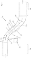
- FIG. 2 Illustrates one in FIG. 1 not shown in detail part of the compressor assembly 1a, namely a compressor intermediate housing 1ac. Shown again is a longitudinal section (the longitudinal axis 2 lies in the cutting plane).
- the intermediate compressor housing 1ac connects the low-pressure compressor 1aa to the high-pressure compressor 1ab. Since the compressors 1aa, 1ab rotate at different speeds (cf. FIG. 1 they run on different shafts), they are radially dimensioned differently.
- the compressor gas duct 4 lies radially further outward than in the region of the high-pressure compressor 1ab. Accordingly, the compressor gas channel 4 extends curved in the region of the compressor intermediate housing 1ac.
- the compressor gas channel 4 is enclosed radially between an inner housing wall 20 and an outer housing wall 21.
- An inner housing wall surface 20a of the inner housing wall 20 bounds the compressor gas channel 4 radially inward
- the outer housing wall surface 21a of the outer housing wall 21 bounds it radially outwardly.
- a bypass flow structure 22 is arranged in the compressor gas duct 4, cf. for illustration also the section according to FIG. 3 .
- the flow around structure 22 is formed as a blade and has a front edge 22 a, and a trailing edge 22 b. Furthermore, in the present case, it fulfills a support function, ie it constitutes a load-bearing connection between radially inward and outward parts of the intermediate compressor housing 1ac.
- the inner housing wall surface 20a is also curved in sections, namely in a first section convex and concave in a second section.
- the convex curvature leads to a flow at the interface heavily loaded.
- an outlet opening 23 is therefore arranged in the curvature in the convex section, through which a relatively small portion of the compressor gas 3 is blown out as outlet gas 24.
- This outlet gas 24 is collected in a collection point 26 and through an outlet channel 25, which extends through the flow around structure 22, brought radially outside of the compressor gas channel 4.
- FIG. 3 shows the Umströmungs Medical 22 in a section, see. the section line AA according to FIG. 2 , In addition to front 22a and rear edge 22b, the side surfaces 22c, d can also be seen in this section. Furthermore, the arrangement of the outlet channel 25 can be seen, the outlet gas 24 flows through perpendicular or oblique to the plane of the drawing.
- the outlet channel 25 can, for example, be taken into account when produced in a casting process via a casting core, but the bypass structure 22 can also be constructed, for example, in a generative manner in layers (the outlet channel 25 remains free).
- FIGS. 4a - c now show two such Umströmungs Quilten 22, which follow one another in the direction of rotation 40.
- approximately 10 flow-around structures 22 can be provided over the entire circulation, cf. also the description introduction.
- the outlet opening 23 extends in the circumferential direction 40 and is arranged upstream of the bypass flow structures 22 with respect to the compressor gas flow.
- the variant according to FIG. 4b shows an elongated outlet opening 23, which extends in this case, however, with respect to the circulating direction 40 between the Umströmungs Modellen 22.
- Variants according to FIGS. 4c, d each have a plurality of outlet openings 23. These may be grouped together, wherein the respective omitted outlet gas 24 is then brought together in the collection point 26 and brought by a common outlet channel 25 radially outward (see also FIG. 2 with respect to the collection point 26). Apart from that, the outlet openings 23 analogous to FIGS. 4a, b the Umströmungs Modellen 22 upstream or be arranged in the circumferential direction 40 therebetween.
- compressor assembly 1a Low-pressure compressor 1aa High-pressure compressors 1ab Intermediate compressor housing 1ac combustion chamber 1b turbine 1c Longitudinal axis (the turbomachine) 2 compressor gas 3 Compressor gas channel 4 Inner housing wall 20 Inner housing wall surface 20a Outer housing wall 21 Outer casing wall surface 21a Umströmungs Medical 22 Leading edge of it 22a Trailing edge of it 22b faces 22c, d outlet 23 outlet gas 24 exhaust port 25 collection 26 direction of rotation 40
Landscapes
- Engineering & Computer Science (AREA)
- Mechanical Engineering (AREA)
- General Engineering & Computer Science (AREA)
- Chemical & Material Sciences (AREA)
- Combustion & Propulsion (AREA)
- Physics & Mathematics (AREA)
- Fluid Mechanics (AREA)
- Life Sciences & Earth Sciences (AREA)
- Sustainable Development (AREA)
- Structures Of Non-Positive Displacement Pumps (AREA)
Abstract
Description
- Die vorliegende Erfindung betrifft ein Verdichtermodul für eine Strömungsmaschine.
- Bei der Strömungsmaschine kann es sich bspw. um ein Strahltriebwerk handeln, z. B. um ein Mantelstromtriebwerk. Funktional gliedert sich die Strömungsmaschine in Verdichter, Brennkammer und Turbine. Etwa im Falle des Strahltriebwerks wird angesaugte Luft vom Verdichter komprimiert und in der nachgelagerten Brennkammer mit hinzugemischtem Kerosin verbrannt. Das entstehende Heißgas, eine Mischung aus Verbrennungsgas und Luft, durchströmt die nachgelagerte Turbine und wird dabei expandiert. Dabei entzieht die Turbine dem Heißgas anteilig auch Energie, um den Verdichter anzutreiben.
- Der vorliegende Gegenstand richtet sich auf den Verdichter bzw. ein Modul davon; der Gegenstand soll aber zunächst ausdrücklich nicht auf das zur Illustration in Bezug genommene Strahltriebwerk beschränkt sein, es ist bspw. auch eine Anwendung in einer stationären Gasturbine möglich.
- Der vorliegenden Erfindung liegt das technische Problem zugrunde, ein besonders vorteilhaftes Verdichtermodul für eine Strömungsmaschine anzugeben.
- Erfindungsgemäß wird dies mit einem Verdichtermodul gemäß Anspruch 1 gelöst. Dieses bildet einen Verdichtergaskanal zum Führen des zu verdichtenden Gases (im Folgenden auch "Verdichtergas") und weist in dem Verdichtergaskanal eine Umströmungsstruktur auf, die sich radial zwischen einen Innen- und einer Außengehäusewand des Verdichtermoduls erstreckt. Dabei ist in einer Innengehäusewandfläche, mit welcher die Innengehäusewand den Verdichtergaskanal nach radial innen begrenzt, eine Auslassöffnung zum anteiligen Auslassen des Verdichtergases in einen Auslasskanal angeordnet. Dieser Auslasskanal erstreckt sich erfindungsgemäß durch die Umströmungsstruktur nach radial außen, das ausgelassene Gas (im Folgenden auch "Auslassgas") wird also nach radial außerhalb des Verdichtergaskanals geführt. Das Auslassen an der Innengehäusewand kann einerseits strömungstechnisch von Vorteil sein (siehe unten im Detail). Andererseits kann das Führen des Auslassgases nach radial außen bspw. insoweit von Vorteil sein, als dort mehr Bauraum zur Verfügung steht.
- Bevorzugte Ausführungsformen finden sich in den abhängigen Ansprüchen und der gesamten Beschreibung, wobei bei der Darstellung der Merkmale nicht immer im Einzelnen zwischen Vorrichtungs- und Verfahrens- bzw. Verwendungsaspekten unterschieden wird; jedenfalls implizit ist die Offenbarung hinsichtlich sämtlicher Anspruchskategorien zu lesen. Ohne ausdrücklich gegenteilige Angabe beziehen sich die Konkretisierungen stets auf sowohl das Verdichtermodul als auch einen damit ausgestatteten Verdichter bzw. eine entsprechende Strömungsmaschine.
- Das Verdichtergas ist das Gas, das eine der Brennkammer vorgelagerte Verdichteranordnung durchströmt und dabei komprimiert wird, im Falle des Strahltriebwerks also die angesaugte Luft. Zur begrifflichen Unterscheidung wird jener Teil davon, der durch die Auslassöffnung in der Innengehäusewandfläche aus dem Verdichtergaskanal austritt, als "Auslassgas" bezeichnet. Das Verdichtergas tritt aufgrund des Überdrucks im Verdichtergaskanal zu einem (sehr geringen) Anteil durch die Auslassöffnung aus, wird also gewissermaßen ausgeblasen. Das Verdichtermodul bildet den Verdichtergaskanal, in diesem wird das Verdichtergas in Richtung Brennkammereinlass geführt. Nach radial innen wird der Verdichtergaskanal von der Innengehäusewandfläche begrenzt, nach radial außen von einer Außengehäusewandfläche der Außengehäusewand. Die Innengehäusewandfläche und die Außengehäusewandfläche liegen einander radial gegenüber, erstere ist nach radial außen gewandt, letztere nach radial innen.
- Generell bezieht sich im Rahmen dieser Offenbarung "axial" auf die Längsachse des Verdichtermoduls, mithin also die Längsachse des Verdichters bzw. der Strömungsmaschine. Diese Längsachse kann bspw. mit einer Rotationsachse zusammenfallen, um welche die Laufschaufeln einer Verdichterstufe bzw. eines Verdichters rotieren. "Radial" betrifft die dazu senkrechten, von der Längsachse weg weisenden Radialrichtungen, und ein "Umlauf" bzw. die "Umlaufrichtung" oder "umlaufend" betreffen die Drehung um die Längsachse. Ferner sind "ein" und "eine" im Rahmen dieser Offenbarung ohne ausdrücklich gegenteilige Angabe als unbestimmte Artikel und damit stets auch als "mindestens ein" bzw. "mindestens eine" zu lesen. Es kann also bspw. umlaufend verteilt eine Mehrzahl Umströmungsstrukturen geben bzw. auch eine Mehrzahl Auslassöffnungen etc., siehe unten im Detail.
- Das Auslassgas wird durch die Umströmungsstruktur nach radial außerhalb des Verdichtergaskanals gebracht, dort kann bspw. eine weitergehende Führung konstruktiv einfacher als radial innerhalb sein. Der Bauraum radial innerhalb ist begrenzt, und zudem ist bzw. sind dort auch die Wellen mit zugehörigen Lagern etc. angeordnet. Radial außerhalb des Verdichtergaskanals kann das Auslassgas dann bspw. zur Brennkammer bzw. Turbine geführt und als Kühlfluid genutzt werden. Das nach radial außen geführte Auslassgas kann aber bspw. auch weitergehende Anwendungsmöglichkeiten eröffnen, etwa im Falle eines Triebwerks auch vom Flugzeug selbst genutzt werden, z. B. zur Druckversorgung der Kabine oder generell für pneumatische Systeme (Klimaanlage etc.).
- Das Auslassen des Auslassgases an der Innengehäusewandfläche kann bspw. strömungsmechanisch von Vorteil sein, weil damit dicke und somit stark belastete Grenzschichten der Strömung abgebaut werden können. In der Folge kann sich Verdichtergas aus einem Kernbereich der Strömung, wo das Verdichtergas eine höhere kinetische Energie hat, zur Innengehäusewandfläche hin verlagern, was der Auslassöffnung nachgelagert eine neu ausgebildete Grenzschicht höherer Energie ergibt. Diese ist dann bspw. weniger verlustbehaftet und damit weniger ablösegefährdet. Ein solcher strömungsmechanischer Vorteil kann sich insbesondere in einer Krümmung ergeben, aber auch einer Krümmung vorgelagert von Vorteil sein (nämlich einer Akkumulation belasteter Grenzschichten vorbeugen helfen).
- Bei einer bevorzugten Ausführungsform erstreckt sich die Innengehäusewandfläche axial mit einer abschnittsweisen Krümmung. Diese Krümmung besteht also in Bezug Schnittebenen, die jeweils die Längsachse (siehe oben) beinhalten. Aus Sicht des strömenden Verdichtergases bedingt die Krümmung eine Richtungsänderung bzw. einen Versatz, was die Grenzflächen strömungsmechanisch belastet. Bevorzugt erstreckt sich die Krümmung axial nicht über die gesamte Innengehäusewandfläche, sondern nur über in einen Teil davon, an den stromauf- und/oder stromabwärts Abschnitte anschließen, die für sich in besagten Schnittebenen betrachtet gerade sind. Ohne ausdrücklich gegenteilige Angabe beziehen sich stromauf/stromab bzw. vor-/nachgelagert auf das Verdichtergas im Verdichtergaskanal.
- Die Auslassöffnung ist bevorzugt in der Krümmung und/oder der Krümmung vorgelagert angeordnet. Letzteres kann bspw. insoweit vorteilhaft sein, als dann vor der strömungsmechanisch eigentlich kritischen Krümmung eine zuvor aufgebaute belastete Grenzschicht zumindest teilweise abgebaut werden kann. Es ist ausdrücklich auch eine Kombination möglich, die Auslassöffnung kann sich also anteilig der Krümmung vorgelagert und in diese hinein erstrecken.
- In bevorzugter Ausgestaltung verläuft die Innengehäusewandfläche im Bereich der Krümmung konvex, was sich wiederum auf die die Längsachse beinhaltenden Schnittebenen bezieht. Mit der Auslassöffnung kann einem Abreißen der Strömung dort vorgebeugt werden.
- Bei einer bevorzugten Ausführungsform ist die Umströmungsstruktur als Schaufel ausgebildet, hat sie also bezogen auf die Umströmung mit dem Verdichtergas stromauf eine Vorderkante und stromab eine Hinterkante. Zwischen Vorder- und Hinterkante erstrecken sich zwei einander entgegengesetzte Seitenflächen, die Schaufel kann profiliert oder auch unprofiliert ausgeführt sein. Bevorzugt ist eine Seitenfläche als Saugseitenfläche und die andere als Druckseitenfläche ausgebildet.
- In bevorzugter Ausgestaltung ist die als Schaufel ausgebildete Umströmungsstruktur bezogen auf die Umströmung mit dem Verdichtergas allenfalls schwach umlenkend ausgebildet. Dies meint eine Umlenkung von nicht mehr als 5°, 4° bzw. 3° (in Reihenfolge der Nennung zunehmend bevorzugt). Die Schaufel kann auch nicht umlenkend vorgesehen sein (0°), es kann aber andererseits auch eine Untergrenze bei bspw. mindestens 1° liegen.
- Bei einer bevorzugten Ausführungsform bildet die Umströmungsstruktur entweder selbst eine tragende Stützstrebe oder stellt sie eine Verkleidung einer solchen tragenden Stützstrebe dar. Bevorzugt ist eine Kombination mit der Ausgestaltung als Schaufel, die dann auch als Stützschaufel bzw. Strut bezeichnet wird. Eine "Stützstrebe" ist ein tragender Bestandteil des Verdichtermoduls, der einen radial innerhalb des Verdichtergaskanals angeordneten Innengehäusebereich und einen radial außerhalb davon angeordneten Außengehäusebereich trägt. Bevorzugt kann die Stützstrebe ein Lager der Verdichterwelle tragen, jedenfalls mittelbar. Bevorzugt können dann umlaufend eine Mehrzahl Stützstreben speichenartig vorgesehen sein; miteinander können die Stützstreben das Lager dann zentriert im Gehäuse halten. Einerseits kann die Umströmungsstruktur selbst die Stützstrebe darstellen; die Umströmungsstruktur kann aber andererseits auch als Verkleidung, also Umhüllung der eigentlich tragenden Stützstrebe mit dieser zur strömungsmechanischen Optimierung zusammengesetzt sein.
- Bei einer bevorzugten Ausführungsform begrenzt die Umströmungsstruktur selbst den Auslasskanal, also jedenfalls jenen Abschnitt davon, der sich radial durch die Umströmungsstruktur hindurch erstreckt. Das Umströmungsstrukturmaterial, aus dem die Umströmungsstruktur vorgesehen ist, begrenzt dann also einerseits nach innen den Auslasskanal und bildet andererseits eine dem Verdichtergas zugewandte Außenfläche der Umströmungsstruktur (die aber bspw. auch schutzbeschichtet sein kann). Im Allgemeinen könnte die Umströmungsstruktur hingegen auch lediglich eine Verkleidung/Umhüllung darstellen, in der dann eine den Auslasskanal bildende Fluidleitung oder eine nach außen geführte mechanische Welle verlegt ist. Im Falle der bevorzugten integralen Ausgestaltung kann der Auslasskanal bspw. bei einer gießtechnischen Herstellung bereits in der Gussform berücksichtigt werden. Dies ist aber nicht zwingend, die Umströmungsstruktur kann bspw. auch generativ aufgebaut werden (aus einem Datenmodell durch schichtweises selektives Verfestigen eines Werkstoffs), wobei ebenfalls ein integraler Auslasskanal berücksichtigt werden kann.
- Bei einer bevorzugten Ausführungsform ist zumindest ein Abschnitt der Auslassöffnung der Umströmungsstruktur vorgelagert (bezogen auf die Verdichtergasströmung). Es kann sich auch die gesamte Auslassöffnung der Umströmungsstruktur vorgelagert erstrecken, also bspw. stromauf der Vorderkante einer vorstehend beschriebenen Schaufel liegen. Andererseits kann sich die Auslassöffnung aber anteilig auch über die Vorderkante der Umströmungsstruktur hinweg nach stromab erstrecken.
- In bevorzugter Ausgestaltung sind umlaufend eine Mehrzahl Umströmungsstrukturen vorgesehen. "Mehrzahl" meint generell mindestens 2, wobei mindestens 3, 4, 5, 6, 7, 8, 9 bzw. 10 in der Reihenfolge der Nennung zunehmend weiter bevorzugt sein können. Von den Untergrenzen unabhängige Obergrenzen können bspw. bei höchstens 100, 80, 60, 40, 30, 20 bzw. 15 liegen. Bevorzugt sind die umlaufend vorgesehenen Umströmungsstrukturen drehsymmetrisch zueinander.
- In bevorzugter Ausgestaltung erstreckt sich zumindest ein Abschnitt der Auslassöffnung bezogen auf die Umlaufrichtung zwischen zwei zueinander umlaufend nächstbenachbarten Umströmungsstrukturen. Die Auslassöffnung kann sich dabei tatsächlich durchgehend von der einen zur nächstbenachbarten Umströmungsstruktur erstrecken, also bspw. eine in Umlaufrichtung langgestreckte Form haben. Andererseits kann die Auslassöffnung bspw. auch eine runde Form haben, etwa elliptisch bzw. insbesondere kreisrund sein. Insbesondere eine solche Auslassöffnung kann die Strecke zwischen den Umströmungsstrukturen dann auch nur anteilig ausfüllen, wobei dann zwischen den Umströmungsstrukturen bevorzugt auch noch (eine) weitere Auslassöffnung(en) vorgesehen sein können.
- Es kann einerseits die gesamte Auslassöffnung zwischen den Umströmungsstrukturen angeordnet sein, andererseits kann sie sich aber auch anteilig den Umströmungsstrukturen vorgelagert erstrecken, siehe vorne. Generell können die eben geschilderten Formgebungen ("in Umlaufrichtung langgestreckt" oder "rund") auch im Falle einer im Gesamten der Umströmungsstruktur vorgelagerten Auslassöffnung von Interesse sein.
- Bei einer bevorzugten Ausführungsform sind in der Innengehäusewandfläche eine Mehrzahl Auslassöffnungen vorgesehen, die gemeinsam dem durch die Umströmungsstruktur nach radial außen geführten Auslasskanal zugeordnet sind. Es wird auf die vorstehenden Angaben zur "Mehrzahl" verwiesen. In der Innengehäusewandfläche kann es dann aber insgesamt noch deutlich mehr Auslassöffnungen geben, die dann jeweils gruppenweise einer jeweiligen Umströmungsstruktur (dem Auslasskanal darin) zugeordnet sind. Das durch die einzelnen, gemeinsam der Umströmungsstruktur zugeordneten Auslassöffnungen austretende Auslassgas kann bspw. in einer Sammelstelle im Innengehäuse zusammengeführt werden. Von dort gelangt es dann durch den Auslasskanal in der Umströmungsstruktur nach radial außen. Eine Sammelstelle im Innengehäuse kann auch generell bevorzugt sein, bspw. um das Auslassgas nach dem Austritt durch die Auslassöffnung und vor dem Führen durch die Umströmungsstruktur zu expandieren.
- In bevorzugter Ausgestaltung ist das Verdichtermodul mit der erfindungsgemäßen Auslassgasführung ein Verdichterzwischengehäuse. Dieses kann bspw. zwischen einem (axial letzten) Verdichter und der Brennkammer angeordnet werden/sein, bevorzugt ist eine Anordnung zwischen zwei Verdichtern. Ein "Verdichter" ist in der Regel aus mehreren Stufen aufgebaut, typischerweise weist jede Stufe einen Lauf- und einen darauf folgenden Leitschaufelkranz auf. Es können bspw. die Laufschaufelkränze eines Verdichters auf derselben Welle drehen und die Laufschaufelkränze eines anderen Verdichters auf einer anderen Welle. Im Allgemeinen kann das im Rahmen dieser Offenbarung beschriebene "Verdichtermodul" auch ein Verdichter sein; der Auslasskanal kann dann durch eine Leitschaufel des Verdichters nach radial außen geführt sein. Bevorzugt ist das Verdichtermodul ein Verdichterzwischengehäuse.
- Die Verdichter können sich untereinander in ihrer radialen Lage unterscheiden, weil sie bspw. mit unterschiedlichen Drehzahlen betrieben werden. Daraus kann sich ein radialer Versatz zwischen den Verdichtern ergeben, was im dazwischen angeordneten Verdichterzwischengehäuse einen gekrümmten Verlauf des Verdichtergaskanals bedingt. Daraus kann insbesondere ein vorstehend beschriebener, gekrümmter Verlauf der Innengehäusewandfläche resultieren. Speziell in den konvex gekrümmten Bereichen ist die Strömung dann stark belastet und lässt sich durch das Anordnen der Auslassöffnung(en) dort die Gefahr eines Ablösens verringern (neu ausgebildete Grenzschicht mit höherer Energie, siehe vorne). Die Problematik der stark belasteten Grenzschichten ließe sich zwar ggf. auch mit einem axial hinreichend langgestrecken Verdichtergaskanal adressieren, allerdings erhöht sich damit die Baulänge der Strömungsmaschine insgesamt. Dies kann bereits wegen des höheren Materialbedarfs nachteilig sein, im Falle eines Flugtriebwerks bedeutet das höhere Gewicht dann letztlich auch einen erhöhten Treibstoffverbrauch.
- Die Erfindung betrifft auch eine Verdichteranordnung, die ein als Verdichterzwischengehäuse ausgebildetes erfindungsgemäßes Verdichtermodul und mindestens einen Verdichter aufweist, vgl. auch die vorstehenden Anmerkungen. Bevorzugt weist die Verdichteranordnung mindestens zwei Verdichter auf, zwischen denen das Verdichterzwischengehäuse angeordnet ist. In der Regel wird die Verdichteranordnung nicht mehr als vier bzw drei Verdichter aufweisen. Bevorzugt kann zwischen sämtlichen Verdichtern jeweils ein erfindungsgemäß ausgestaltetes Verdichterzwischengehäuse angeordnet sein.
- Ebenso betrifft die Erfindung die Verwendung eines vorliegend offenbarten Verdichtermoduls oder einer Verdichteranordnung in einer Strömungsmaschine, im Allgemeinen bspw. auch in einer Gasturbine. Bevorzugt ist die Verwendung in einem Flugtriebwerk, insbesondere einem Strahltriebwerk.
- Im Folgenden wird die Erfindung anhand eines Ausführungsbeispiels näher erläutert, wobei die einzelnen Merkmale im Rahmen der nebengeordneten Ansprüche auch in anderer Kombination erfindungswesentlich sein können und auch weiterhin nicht im Einzelnen zwischen den unterschiedlichen Anspruchskategorien unterschieden wird.
- Im Einzelnen zeigt
- Figur 1
- ein Strahltriebwerk in einem Längsschnitt;
- Figur 2
- als Teil einer Verdichteranordnung des Strahltriebwerks gemäß
Figur 1 ein Verdichterzwischengehäuse; - Figur 3
- eine Umströmungsstruktur des Verdichterzwischengehäuses gemäß
Figur 2 in einem Schnitt; - Figur4a-d
- jeweils zwei Umströmungsstrukturen gemäß
Figur 3 mit unterschiedlich angeordneten Auslassöffnungen. -
Figur 1 zeigt eine Strömungsmaschine 1 im Schnitt, konkret ein Strahltriebwerk (Mantelstromtriebwerk). Die Strömungsmaschine 1 gliedert sich funktional in Verdichteranordnung 1a, Brennkammer 1b und Turbine 1c. Sowohl die Verdichteranordnung 1a als auch die Turbine 1c sind jeweils aus mehreren Modulen aufgebaut, die Verdichteranordnung 1a vorliegend aus einem Niederdruck- 1aa und einem Hochdruckverdichter 1ab. Jeder Verdichter 1aa, 1ab ist seinerseits aus mehreren Stufen aufgebaut, jede Stufe setzt sich in der Regel aus einem Laufschaufelkranz und einem darauffolgenden Leitschaufelkranz zusammen. Im Betrieb wird die Verdichteranordnung 1a bezogen auf eine Längsachse 2 axial von dem Verdichtergas 3, vorliegend Luft, durchströmt, und zwar in einem Verdichtergaskanal 4. Dabei wird das Verdichtergas 3 komprimiert, in der Brennkammer 1b wird dann Kerosin hinzugemischt und wird diese Mischung verbrannt. -
Figur 2 illustriert einen inFigur 1 nicht im Einzelnen dargestellten Teil der Verdichteranordnung 1a, nämlich ein Verdichterzwischengehäuse 1ac. Gezeigt ist wiederum ein Längsschnitt (die Längsachse 2 liegt in der Schnittebene). Das Verdichterzwischengehäuse 1ac verbindet den Niederdruckverdichter 1aa mit dem Hochdruckverdichter 1ab. Da die Verdichter 1aa, 1ab mit unterschiedlicher Drehzahl drehen (vgl.Figur 1 , sie laufen auf unterschiedlichen Wellen), sind sie radial unterschiedlich bemessen. Im Bereich des Niedrigdruckverdichters 1aa liegt der Verdichtergaskanal 4 radial weiter außen als im Bereich des Hochdruckverdichters 1ab. Dementsprechend erstreckt sich der Verdichtergaskanal 4 im Bereich des Verdichterzwischengehäuses 1ac gekrümmt. - Wie aus
Figur 2 ersichtlich, wird der Verdichtergaskanal 4 radial zwischen einer Innengehäusewand 20 und einer Außengehäusewand 21 eingefasst. Eine Innengehäusewandfläche 20a der Innengehäusewand 20 begrenzt den Verdichtergaskanal 4 nach radial innen, die Außengehäusewandfläche 21a der Außengehäusewand 21 begrenzt ihn nach radial außen. Ferner ist in dem Verdichtergaskanal 4 eine Umströmungsstruktur 22 angeordnet, vgl. zur Illustration auch den Schnitt gemäßFigur 3 . Die Umströmungsstruktur 22 ist als Schaufel ausgebildet und weist eine Vorderkante 22a, sowie eine Hinterkante 22b auf. Ferner erfüllt sie vorliegend eine Stützfunktion, stellt sie also eine tragende Verbindung zwischen radial innerhalb und außerhalb liegenden Teilen des Verdichterzwischengehäuses 1ac dar. - Aufgrund der gekrümmten Erstreckung des Verdichtergaskanals 4 ist die Innengehäusewandfläche 20a abschnittsweise auch gekrümmt, nämlich in einem ersten Abschnitt konvex und in einem zweiten Abschnitt konkav. Insbesondere die konvexe Krümmung führt zu einer an der Grenzfläche stark belasteten Strömung. Vorliegend ist deshalb in der Krümmung in dem konvexen Abschnitt eine Auslassöffnung 23 angeordnet, durch welche ein im Verhältnis kleiner Teil des Verdichtergases 3 als Auslassgas 24 ausgeblasen wird. Dieses Auslassgas 24 wird in einer Sammelstelle 26 gesammelt und durch einen Auslasskanal 25, welcher sich durch die Umströmungsstruktur 22 erstreckt, nach radial außerhalb des Verdichtergaskanals 4 gebracht. Dort steht mehr Bauraum zur Verfügung bzw. ergeben sich weitergehende Nutzungsmöglichkeiten, vgl. die Beschreibungseinleitung.
-
Figur 3 zeigt die Umströmungsstruktur 22 in einem Schnitt, vgl. die Schnittlinie AA gemäßFigur 2 . Zusätzlich zu Vorder- 22a und Hinterkante 22b sind in diesem Schnitt auch die Seitenflächen 22c,d zu erkennen. Ferner ist auch die Anordnung des Auslasskanals 25 ersichtlich, den das Auslassgas 24 senkrecht bzw. schräg zur Zeichenebene durchströmt. Der Auslasskanal 25 kann bspw. bei einer Herstellung in einem Gießverfahren über einen Gusskern berücksichtigt werden, die Umströmungsstruktur 22 kann aber bspw. auch generativ schichtweise aufgebaut werden (wobei der Auslasskanal 25 frei bleibt). - Die
Figuren 4a - c zeigen nun jeweils zwei solche Umströmungsstrukturen 22, die in Umlaufrichtung 40 aufeinander folgen. Über den gesamten Umlauf können bspw. rund 10 Umströmungsstrukturen 22 vorgesehen sein, vgl. auch die Beschreibungseinleitung. - Bei der Variante gemäß
Figur 4a erstreckt sich die Auslassöffnung 23 in der Umlaufrichtung 40 langgestreckt und ist sie in Bezug auf die Verdichtergasströmung den Umströmungsstrukturen 22 vorgelagert angeordnet. Auch die Variante gemäßFigur 4b zeigt eine langgestreckte Auslassöffnung 23, die sich in diesem Fall jedoch bezogen auf die Umlaufrichtung 40 zwischen den Umströmungsstrukturen 22 erstreckt. - Die Varianten gemäß den
Figuren 4c,d zeigen jeweils mehrere Auslassöffnungen 23. Diese können gruppenweise zusammengefasst sein, wobei das jeweilig ausgelassene Auslassgas 24 dann in der Sammelstelle 26 zusammengeführt und durch einen gemeinsamen Auslasskanal 25 nach radial außerhalb gebracht wird (vgl. auchFigur 2 bzgl. der Sammelstelle 26). Davon abgesehen können die Auslassöffnungen 23 analog denFiguren 4a,b den Umströmungsstrukturen 22 vorgelagert oder auch in der Umlaufrichtung 40 dazwischen angeordnet sein. -
Strömungsmaschine 1 Verdichteranordnung 1a Niederdruckverdichter 1aa Hochdruckverdichter 1ab Verdichterzwischengehäuse 1ac Brennkammer 1b Turbine 1c Längsachse (der Strömungsmaschine) 2 Verdichtergas 3 Verdichtergaskanal 4 Innengehäusewand 20 Innengehäusewandfläche 20a Außengehäusewand 21 Außengehäusewandfläche 21a Umströmungsstruktur 22 Vorderkante davon 22a Hinterkante davon 22b Seitenflächen 22c,d Auslassöffnung 23 Auslassgas 24 Auslasskanal 25 Sammelstelle 26 Umlaufrichtung 40
Claims (15)
- Verdichtermodul (1aa, 1ab, 1ac) für eine Strömungsmaschine (1),
welches Verdichtermodul (1aa, 1ab, 1ac) einen Verdichtergaskanal (4) zum Führen eines zu verdichtenden Verdichtergases (3) bildet,
wobei sich durch den Verdichtergaskanal (4) eine Umströmungsstruktur (22) radial zwischen einer Innengehäusewand (20) und einer Außengehäusewand (21) erstreckt,
und wobei in einer Innengehäusewandfläche (20a), mit welcher die Innengehäusewand (20) den Verdichtergaskanal (4) nach radial innen begrenzt, eine Auslassöffnung (23) zum anteiligen Auslassen des in dem Verdichtergaskanal (4) geführten Verdichtergases (3) angeordnet ist,
wobei sich zum Führen des durch die Auslassöffnung (23) ausgelassenen Auslassgases (24) an die Auslassöffnung (23) ein Auslasskanal (25) anschließt,
und wobei sich der Auslasskanal (25) durch die Umströmungsstruktur (22) nach radial außerhalb des Verdichtergaskanals (4) erstreckt. - Verdichtermodul (1aa, 1ab, 1ac) nach Anspruch 1, bei welchem sich die Innengehäusewandfläche (20a) axial mit einer Krümmung erstreckt und die Auslassöffnung (23) in der Krümmung und/oder der Krümmung vorgelagert angeordnet ist, bezogen auf das in dem Verdichtergaskanal (4) geführte Verdichtergas (3).
- Verdichtermodul (1aa, 1ab, 1ac) nach Anspruch 2, bei welchem die Innengehäusewandfläche (20a) in der Krümmung konvex gekrümmt ist.
- Verdichtermodul (1aa, 1ab, 1ac) nach einem der vorstehenden Ansprüche, bei welchem die Umströmungsstruktur (22) als Schaufel ausgebildet ist, die in Bezug auf die Umströmung mit dem in dem Verdichtergaskanal (4) geführten Verdichtergas (3) eine Vorderkante (22a) und eine Hinterkante (22b) aufweist, sowie zwei sich jeweils zwischen der Vorder- (22a) und der Hinterkante (22b) erstreckende Seitenflächen (22c,d).
- Verdichtermodul (1aa, 1ab, 1ac) nach Anspruch 4, bei welchem die Schaufel allenfalls schwach, nämlich um höchstens 5° umlenkend ausgebildet ist.
- Verdichtermodul (1aa, 1ab, 1ac) nach einem der vorstehenden Ansprüche, bei welchem die Umströmungsstruktur (22) eine tragende Stützstrebe bildet oder eine Verkleidung einer solchen darstellt.
- Verdichtermodul (1aa, 1ab, 1ac) nach einem der vorstehenden Ansprüche, bei welchem die Umströmungsstruktur (22) selbst in ihrem Inneren zumindest einen Abschnitt des Auslasskanals (25) begrenzt.
- Verdichtermodul (1aa, 1ab, 1ac) nach einem der vorstehenden Ansprüche, bei welchem sich die Auslassöffnung (23) bezogen auf das in dem Verdichtergaskanal (4) geführte Verdichtergas (3) zumindest anteilig der Umströmungsstruktur (22) vorgelagert erstreckt.
- Verdichtermodul (1aa, 1ab, 1ac) nach einem der vorstehenden Ansprüche, bei welchem in dem Verdichtergaskanal (4) in Umlaufrichtung verteilt eine Mehrzahl Umströmungsstrukturen (22) vorgesehen sind.
- Verdichtermodul (1aa, 1ab, 1ac) nach Anspruch 9, bei welchem sich die Auslassöffnung (23) bezogen auf die Umlaufrichtung zumindest anteilig zwischen zwei zueinander nächstbenachbarten der Umströmungsstrukturen (22) angeordnet sind.
- Verdichtermodul (1aa, 1ab, 1ac) nach einem der vorstehenden Ansprüche, bei welchem in der Innengehäusewandfläche (20a) eine Mehrzahl Auslassöffnungen (23) vorgesehen sind, die gemeinsam dem sich durch die Umströmungsstruktur (22) nach radial außerhalb erstreckenden Auslasskanal (25) zugeordnet sind.
- Verdichtermodul (1aa, 1ab, 1ac) nach einem der vorstehenden Ansprüche, das als Verdichterzwischengehäuse (1ac) ausgebildet ist.
- Verdichteranordnung (1a) zum Komprimieren von Verdichtergas (3) für eine Strömungsmaschine (1), mit einem als Verdichterzwischengehäuse (1ac) ausgebildeten Verdichtermodul nach Anspruch 12 und einem Verdichter (1aa), welcher dem Verdichterzwischengehäuse (1ac) vorgelagert angeordnet ist.
- Verdichteranordnung (1a) nach Anspruch 13 mit einem weiteren Verdichter (1ab), welcher dem als Verdichterzwischengehäuse (1ac) ausgebildeten Verdichtermodul nachgelagert angeordnet ist.
- Verwendung eines Verdichtermoduls (1aa, 1ab, 1ac) nach einem der Ansprüche 1 bis 12 oder einer Verdichteranordnung (1a) nach Anspruch 13 oder 14 für eine Strömungsmaschine (1), insbesondere ein Strahltriebwerk.
Applications Claiming Priority (1)
| Application Number | Priority Date | Filing Date | Title |
|---|---|---|---|
| DE102017222210.7A DE102017222210A1 (de) | 2017-12-07 | 2017-12-07 | Verdichtermodul für eine Strömungsmaschine |
Publications (2)
| Publication Number | Publication Date |
|---|---|
| EP3495639A1 true EP3495639A1 (de) | 2019-06-12 |
| EP3495639B1 EP3495639B1 (de) | 2023-09-20 |
Family
ID=64604471
Family Applications (1)
| Application Number | Title | Priority Date | Filing Date |
|---|---|---|---|
| EP18209949.9A Active EP3495639B1 (de) | 2017-12-07 | 2018-12-04 | Verdichtermodul für eine strömungsmaschine, das die grenzschicht in einem verdichterzwischengehäuse abbaut |
Country Status (3)
| Country | Link |
|---|---|
| US (1) | US20190178098A1 (de) |
| EP (1) | EP3495639B1 (de) |
| DE (1) | DE102017222210A1 (de) |
Families Citing this family (3)
| Publication number | Priority date | Publication date | Assignee | Title |
|---|---|---|---|---|
| GB2558917B (en) * | 2017-01-19 | 2021-02-10 | Gkn Aerospace Sweden Ab | Transition duct of a multi-stage compressor with areas of different surface roughness |
| US12006846B2 (en) * | 2017-11-02 | 2024-06-11 | MTU Aero Engines AG | Additively manufactured intermediate duct for disposition between a low-pressure compressor and a high-pressure compressor, and corresponding manufacturing method |
| CN115306582B (zh) * | 2022-08-26 | 2025-05-02 | 中国商用飞机有限责任公司 | 一种涡扇发动机的进排气模拟装置 |
Citations (6)
| Publication number | Priority date | Publication date | Assignee | Title |
|---|---|---|---|---|
| US2720356A (en) * | 1952-06-12 | 1955-10-11 | John R Erwin | Continuous boundary layer control in compressors |
| GB814745A (en) * | 1956-01-05 | 1959-06-10 | United Aircraft Corp | An axial flow compressor |
| US5845482A (en) * | 1994-10-06 | 1998-12-08 | Carscallen; William E. | Combined bleed valve and annular diffuser for gas turbine inter compressor duct |
| US20050081530A1 (en) * | 2003-10-15 | 2005-04-21 | Bagnall Adam M. | Arrangement for bleeding the boundary layer from an aircraft engine |
| EP2177770A2 (de) * | 2008-10-20 | 2010-04-21 | Rolls-Royce Deutschland Ltd & Co KG | Verdichter für eine Gasturbine |
| US20150176494A1 (en) * | 2012-05-02 | 2015-06-25 | Gkn Aerospace Sweden Ab | Supporting structure for a gas turbine engine |
Family Cites Families (3)
| Publication number | Priority date | Publication date | Assignee | Title |
|---|---|---|---|---|
| DE102010023703A1 (de) * | 2010-06-14 | 2011-12-15 | Rolls-Royce Deutschland Ltd & Co Kg | Turbomaschine mit Geräuschreduzierung |
| DE102010023938A1 (de) * | 2010-06-16 | 2011-12-22 | Eads Deutschland Gmbh | Angetriebenes Fluggerät, insbesondere als Nurflügler und/oder mit geringer Radarsignatur ausgebildetes Fluggerät |
| US9435211B2 (en) * | 2014-05-09 | 2016-09-06 | United Technologies Corporation | Method for forming components using additive manufacturing and re-melt |
-
2017
- 2017-12-07 DE DE102017222210.7A patent/DE102017222210A1/de not_active Withdrawn
-
2018
- 2018-12-04 EP EP18209949.9A patent/EP3495639B1/de active Active
- 2018-12-05 US US16/210,786 patent/US20190178098A1/en not_active Abandoned
Patent Citations (6)
| Publication number | Priority date | Publication date | Assignee | Title |
|---|---|---|---|---|
| US2720356A (en) * | 1952-06-12 | 1955-10-11 | John R Erwin | Continuous boundary layer control in compressors |
| GB814745A (en) * | 1956-01-05 | 1959-06-10 | United Aircraft Corp | An axial flow compressor |
| US5845482A (en) * | 1994-10-06 | 1998-12-08 | Carscallen; William E. | Combined bleed valve and annular diffuser for gas turbine inter compressor duct |
| US20050081530A1 (en) * | 2003-10-15 | 2005-04-21 | Bagnall Adam M. | Arrangement for bleeding the boundary layer from an aircraft engine |
| EP2177770A2 (de) * | 2008-10-20 | 2010-04-21 | Rolls-Royce Deutschland Ltd & Co KG | Verdichter für eine Gasturbine |
| US20150176494A1 (en) * | 2012-05-02 | 2015-06-25 | Gkn Aerospace Sweden Ab | Supporting structure for a gas turbine engine |
Also Published As
| Publication number | Publication date |
|---|---|
| EP3495639B1 (de) | 2023-09-20 |
| US20190178098A1 (en) | 2019-06-13 |
| DE102017222210A1 (de) | 2019-06-13 |
Similar Documents
| Publication | Publication Date | Title |
|---|---|---|
| EP2362065B1 (de) | Nebenstromkanal mit Nachleitschaufelkranz in einem Turbofantriebwerk | |
| DE60124572T2 (de) | Halbaxial- und kreiselverdichter für ein gasturbinentriebwerk | |
| EP2796668B1 (de) | Gehäuseabschnitt einer Turbomaschinenverdichter- oder Turbomaschinenturbinenstufe | |
| EP3686396B1 (de) | Leitgitter für eine strömungsmaschine | |
| EP2179143B1 (de) | Spaltkühlung zwischen brennkammerwand und turbinenwand einer gasturbinenanlage | |
| EP2993357B1 (de) | Radialverdichterstufe | |
| DE2042478A1 (de) | Gasturbinenstrahltriebwerk für Flugzeuge mit Einrichtungen zur Bauteilkühlung und Verdichterregelung | |
| EP2647795A1 (de) | Dichtungssystem für eine Strömungsmaschine | |
| CH710476A2 (de) | Verdichter mit einer Axialverdichterendwandeinrichtung zur Steuerung der Leckageströmung in dieser. | |
| DE102014009735A1 (de) | Schaufel und Laufrad einer Strömungsmaschine, sowie Herstellverfahren dafür | |
| EP3431708B1 (de) | Umströmungsanordnung, zugehörige strömungsmaschine und verwendung | |
| DE102022133702A1 (de) | Mantelstromtriebwerk | |
| EP3495639B1 (de) | Verdichtermodul für eine strömungsmaschine, das die grenzschicht in einem verdichterzwischengehäuse abbaut | |
| EP3561236B1 (de) | Leitschaufel für eine turbine einer strömungsmaschine, turbinenmodul und verwendung eines turbinenmoduls | |
| EP3581760B1 (de) | Schaufelblatt für eine thermische strömungsmaschine | |
| EP3530880A1 (de) | Leitschaufelblatt mit geneigtem abschnitt, zugehöriges leitschaufelsegment, modul, strömungsmaschine und verfahren zum entwerfen eines moduls | |
| WO2006024273A1 (de) | Rotor für ein triebwerk | |
| DE102010002395B4 (de) | Turbofantriebwerk mit im Nebenstromkanal angeordneten Leitschaufeln und Stützstreben | |
| DE112014003154B4 (de) | Spiralstruktur und Turbolader | |
| DE60002781T2 (de) | Nabe-Achse Verbindung | |
| WO2021110192A1 (de) | Leitschaufelanordnung für eine strömungsmaschine | |
| EP4265888A1 (de) | Leit- und laufschaufelkranz für ein mantelstromtriebwerk | |
| DE102019216636A1 (de) | Leitschaufelanordnung für eine strömungsmaschine | |
| WO2012097798A1 (de) | Zwischengehäuse einer gasturbine mit einer aussen liegenden begrenzungswand welches stromaufwärts einer stützrippe eine in umfangrichtung verändernde kontur aufweist zur verringerung der sekundärströmungsverluste | |
| DE102020122601A1 (de) | Dichtungssystem, Getriebe mit einem Dichtungssystem und Gasturbinentriebwerk mit einem Dichtungssystem |
Legal Events
| Date | Code | Title | Description |
|---|---|---|---|
| PUAI | Public reference made under article 153(3) epc to a published international application that has entered the european phase |
Free format text: ORIGINAL CODE: 0009012 |
|
| STAA | Information on the status of an ep patent application or granted ep patent |
Free format text: STATUS: THE APPLICATION HAS BEEN PUBLISHED |
|
| AK | Designated contracting states |
Kind code of ref document: A1 Designated state(s): AL AT BE BG CH CY CZ DE DK EE ES FI FR GB GR HR HU IE IS IT LI LT LU LV MC MK MT NL NO PL PT RO RS SE SI SK SM TR |
|
| AX | Request for extension of the european patent |
Extension state: BA ME |
|
| STAA | Information on the status of an ep patent application or granted ep patent |
Free format text: STATUS: REQUEST FOR EXAMINATION WAS MADE |
|
| 17P | Request for examination filed |
Effective date: 20191204 |
|
| RBV | Designated contracting states (corrected) |
Designated state(s): AL AT BE BG CH CY CZ DE DK EE ES FI FR GB GR HR HU IE IS IT LI LT LU LV MC MK MT NL NO PL PT RO RS SE SI SK SM TR |
|
| STAA | Information on the status of an ep patent application or granted ep patent |
Free format text: STATUS: EXAMINATION IS IN PROGRESS |
|
| 17Q | First examination report despatched |
Effective date: 20210204 |
|
| GRAP | Despatch of communication of intention to grant a patent |
Free format text: ORIGINAL CODE: EPIDOSNIGR1 |
|
| STAA | Information on the status of an ep patent application or granted ep patent |
Free format text: STATUS: GRANT OF PATENT IS INTENDED |
|
| INTG | Intention to grant announced |
Effective date: 20230424 |
|
| GRAS | Grant fee paid |
Free format text: ORIGINAL CODE: EPIDOSNIGR3 |
|
| GRAA | (expected) grant |
Free format text: ORIGINAL CODE: 0009210 |
|
| STAA | Information on the status of an ep patent application or granted ep patent |
Free format text: STATUS: THE PATENT HAS BEEN GRANTED |
|
| AK | Designated contracting states |
Kind code of ref document: B1 Designated state(s): AL AT BE BG CH CY CZ DE DK EE ES FI FR GB GR HR HU IE IS IT LI LT LU LV MC MK MT NL NO PL PT RO RS SE SI SK SM TR |
|
| REG | Reference to a national code |
Ref country code: GB Ref legal event code: FG4D Free format text: NOT ENGLISH |
|
| REG | Reference to a national code |
Ref country code: CH Ref legal event code: EP |
|
| REG | Reference to a national code |
Ref country code: DE Ref legal event code: R096 Ref document number: 502018013276 Country of ref document: DE |
|
| REG | Reference to a national code |
Ref country code: IE Ref legal event code: FG4D Free format text: LANGUAGE OF EP DOCUMENT: GERMAN |
|
| REG | Reference to a national code |
Ref country code: LT Ref legal event code: MG9D |
|
| PG25 | Lapsed in a contracting state [announced via postgrant information from national office to epo] |
Ref country code: GR Free format text: LAPSE BECAUSE OF FAILURE TO SUBMIT A TRANSLATION OF THE DESCRIPTION OR TO PAY THE FEE WITHIN THE PRESCRIBED TIME-LIMIT Effective date: 20231221 |
|
| REG | Reference to a national code |
Ref country code: NL Ref legal event code: MP Effective date: 20230920 |
|
| PG25 | Lapsed in a contracting state [announced via postgrant information from national office to epo] |
Ref country code: SE Free format text: LAPSE BECAUSE OF FAILURE TO SUBMIT A TRANSLATION OF THE DESCRIPTION OR TO PAY THE FEE WITHIN THE PRESCRIBED TIME-LIMIT Effective date: 20230920 Ref country code: RS Free format text: LAPSE BECAUSE OF FAILURE TO SUBMIT A TRANSLATION OF THE DESCRIPTION OR TO PAY THE FEE WITHIN THE PRESCRIBED TIME-LIMIT Effective date: 20230920 Ref country code: NO Free format text: LAPSE BECAUSE OF FAILURE TO SUBMIT A TRANSLATION OF THE DESCRIPTION OR TO PAY THE FEE WITHIN THE PRESCRIBED TIME-LIMIT Effective date: 20231220 Ref country code: LV Free format text: LAPSE BECAUSE OF FAILURE TO SUBMIT A TRANSLATION OF THE DESCRIPTION OR TO PAY THE FEE WITHIN THE PRESCRIBED TIME-LIMIT Effective date: 20230920 Ref country code: LT Free format text: LAPSE BECAUSE OF FAILURE TO SUBMIT A TRANSLATION OF THE DESCRIPTION OR TO PAY THE FEE WITHIN THE PRESCRIBED TIME-LIMIT Effective date: 20230920 Ref country code: HR Free format text: LAPSE BECAUSE OF FAILURE TO SUBMIT A TRANSLATION OF THE DESCRIPTION OR TO PAY THE FEE WITHIN THE PRESCRIBED TIME-LIMIT Effective date: 20230920 Ref country code: GR Free format text: LAPSE BECAUSE OF FAILURE TO SUBMIT A TRANSLATION OF THE DESCRIPTION OR TO PAY THE FEE WITHIN THE PRESCRIBED TIME-LIMIT Effective date: 20231221 Ref country code: FI Free format text: LAPSE BECAUSE OF FAILURE TO SUBMIT A TRANSLATION OF THE DESCRIPTION OR TO PAY THE FEE WITHIN THE PRESCRIBED TIME-LIMIT Effective date: 20230920 |
|
| PG25 | Lapsed in a contracting state [announced via postgrant information from national office to epo] |
Ref country code: NL Free format text: LAPSE BECAUSE OF FAILURE TO SUBMIT A TRANSLATION OF THE DESCRIPTION OR TO PAY THE FEE WITHIN THE PRESCRIBED TIME-LIMIT Effective date: 20230920 |
|
| PG25 | Lapsed in a contracting state [announced via postgrant information from national office to epo] |
Ref country code: IS Free format text: LAPSE BECAUSE OF FAILURE TO SUBMIT A TRANSLATION OF THE DESCRIPTION OR TO PAY THE FEE WITHIN THE PRESCRIBED TIME-LIMIT Effective date: 20240120 |
|
| PG25 | Lapsed in a contracting state [announced via postgrant information from national office to epo] |
Ref country code: ES Free format text: LAPSE BECAUSE OF FAILURE TO SUBMIT A TRANSLATION OF THE DESCRIPTION OR TO PAY THE FEE WITHIN THE PRESCRIBED TIME-LIMIT Effective date: 20230920 |
|
| PG25 | Lapsed in a contracting state [announced via postgrant information from national office to epo] |
Ref country code: SM Free format text: LAPSE BECAUSE OF FAILURE TO SUBMIT A TRANSLATION OF THE DESCRIPTION OR TO PAY THE FEE WITHIN THE PRESCRIBED TIME-LIMIT Effective date: 20230920 Ref country code: RO Free format text: LAPSE BECAUSE OF FAILURE TO SUBMIT A TRANSLATION OF THE DESCRIPTION OR TO PAY THE FEE WITHIN THE PRESCRIBED TIME-LIMIT Effective date: 20230920 Ref country code: IS Free format text: LAPSE BECAUSE OF FAILURE TO SUBMIT A TRANSLATION OF THE DESCRIPTION OR TO PAY THE FEE WITHIN THE PRESCRIBED TIME-LIMIT Effective date: 20240120 Ref country code: ES Free format text: LAPSE BECAUSE OF FAILURE TO SUBMIT A TRANSLATION OF THE DESCRIPTION OR TO PAY THE FEE WITHIN THE PRESCRIBED TIME-LIMIT Effective date: 20230920 Ref country code: EE Free format text: LAPSE BECAUSE OF FAILURE TO SUBMIT A TRANSLATION OF THE DESCRIPTION OR TO PAY THE FEE WITHIN THE PRESCRIBED TIME-LIMIT Effective date: 20230920 Ref country code: CZ Free format text: LAPSE BECAUSE OF FAILURE TO SUBMIT A TRANSLATION OF THE DESCRIPTION OR TO PAY THE FEE WITHIN THE PRESCRIBED TIME-LIMIT Effective date: 20230920 Ref country code: SK Free format text: LAPSE BECAUSE OF FAILURE TO SUBMIT A TRANSLATION OF THE DESCRIPTION OR TO PAY THE FEE WITHIN THE PRESCRIBED TIME-LIMIT Effective date: 20230920 Ref country code: PT Free format text: LAPSE BECAUSE OF FAILURE TO SUBMIT A TRANSLATION OF THE DESCRIPTION OR TO PAY THE FEE WITHIN THE PRESCRIBED TIME-LIMIT Effective date: 20240122 |
|
| PG25 | Lapsed in a contracting state [announced via postgrant information from national office to epo] |
Ref country code: PL Free format text: LAPSE BECAUSE OF FAILURE TO SUBMIT A TRANSLATION OF THE DESCRIPTION OR TO PAY THE FEE WITHIN THE PRESCRIBED TIME-LIMIT Effective date: 20230920 Ref country code: IT Free format text: LAPSE BECAUSE OF FAILURE TO SUBMIT A TRANSLATION OF THE DESCRIPTION OR TO PAY THE FEE WITHIN THE PRESCRIBED TIME-LIMIT Effective date: 20230920 |
|
| REG | Reference to a national code |
Ref country code: DE Ref legal event code: R097 Ref document number: 502018013276 Country of ref document: DE |
|
| PG25 | Lapsed in a contracting state [announced via postgrant information from national office to epo] |
Ref country code: DK Free format text: LAPSE BECAUSE OF FAILURE TO SUBMIT A TRANSLATION OF THE DESCRIPTION OR TO PAY THE FEE WITHIN THE PRESCRIBED TIME-LIMIT Effective date: 20230920 |
|
| PLBE | No opposition filed within time limit |
Free format text: ORIGINAL CODE: 0009261 |
|
| STAA | Information on the status of an ep patent application or granted ep patent |
Free format text: STATUS: NO OPPOSITION FILED WITHIN TIME LIMIT |
|
| PG25 | Lapsed in a contracting state [announced via postgrant information from national office to epo] |
Ref country code: DK Free format text: LAPSE BECAUSE OF FAILURE TO SUBMIT A TRANSLATION OF THE DESCRIPTION OR TO PAY THE FEE WITHIN THE PRESCRIBED TIME-LIMIT Effective date: 20230920 |
|
| REG | Reference to a national code |
Ref country code: CH Ref legal event code: PL |
|
| PG25 | Lapsed in a contracting state [announced via postgrant information from national office to epo] |
Ref country code: LU Free format text: LAPSE BECAUSE OF NON-PAYMENT OF DUE FEES Effective date: 20231204 |
|
| PG25 | Lapsed in a contracting state [announced via postgrant information from national office to epo] |
Ref country code: MC Free format text: LAPSE BECAUSE OF FAILURE TO SUBMIT A TRANSLATION OF THE DESCRIPTION OR TO PAY THE FEE WITHIN THE PRESCRIBED TIME-LIMIT Effective date: 20230920 |
|
| 26N | No opposition filed |
Effective date: 20240621 |
|
| REG | Reference to a national code |
Ref country code: BE Ref legal event code: MM Effective date: 20231231 |
|
| PG25 | Lapsed in a contracting state [announced via postgrant information from national office to epo] |
Ref country code: MC Free format text: LAPSE BECAUSE OF FAILURE TO SUBMIT A TRANSLATION OF THE DESCRIPTION OR TO PAY THE FEE WITHIN THE PRESCRIBED TIME-LIMIT Effective date: 20230920 Ref country code: LU Free format text: LAPSE BECAUSE OF NON-PAYMENT OF DUE FEES Effective date: 20231204 |
|
| REG | Reference to a national code |
Ref country code: IE Ref legal event code: MM4A |
|
| PG25 | Lapsed in a contracting state [announced via postgrant information from national office to epo] |
Ref country code: IE Free format text: LAPSE BECAUSE OF NON-PAYMENT OF DUE FEES Effective date: 20231204 |
|
| PG25 | Lapsed in a contracting state [announced via postgrant information from national office to epo] |
Ref country code: BE Free format text: LAPSE BECAUSE OF NON-PAYMENT OF DUE FEES Effective date: 20231231 |
|
| PG25 | Lapsed in a contracting state [announced via postgrant information from national office to epo] |
Ref country code: CH Free format text: LAPSE BECAUSE OF NON-PAYMENT OF DUE FEES Effective date: 20231231 |
|
| PG25 | Lapsed in a contracting state [announced via postgrant information from national office to epo] |
Ref country code: SI Free format text: LAPSE BECAUSE OF FAILURE TO SUBMIT A TRANSLATION OF THE DESCRIPTION OR TO PAY THE FEE WITHIN THE PRESCRIBED TIME-LIMIT Effective date: 20230920 |
|
| PG25 | Lapsed in a contracting state [announced via postgrant information from national office to epo] |
Ref country code: SI Free format text: LAPSE BECAUSE OF FAILURE TO SUBMIT A TRANSLATION OF THE DESCRIPTION OR TO PAY THE FEE WITHIN THE PRESCRIBED TIME-LIMIT Effective date: 20230920 Ref country code: IE Free format text: LAPSE BECAUSE OF NON-PAYMENT OF DUE FEES Effective date: 20231204 Ref country code: CH Free format text: LAPSE BECAUSE OF NON-PAYMENT OF DUE FEES Effective date: 20231231 Ref country code: BE Free format text: LAPSE BECAUSE OF NON-PAYMENT OF DUE FEES Effective date: 20231231 |
|
| PG25 | Lapsed in a contracting state [announced via postgrant information from national office to epo] |
Ref country code: BG Free format text: LAPSE BECAUSE OF FAILURE TO SUBMIT A TRANSLATION OF THE DESCRIPTION OR TO PAY THE FEE WITHIN THE PRESCRIBED TIME-LIMIT Effective date: 20230920 |
|
| PG25 | Lapsed in a contracting state [announced via postgrant information from national office to epo] |
Ref country code: BG Free format text: LAPSE BECAUSE OF FAILURE TO SUBMIT A TRANSLATION OF THE DESCRIPTION OR TO PAY THE FEE WITHIN THE PRESCRIBED TIME-LIMIT Effective date: 20230920 |
|
| PGFP | Annual fee paid to national office [announced via postgrant information from national office to epo] |
Ref country code: DE Payment date: 20241216 Year of fee payment: 7 |
|
| PGFP | Annual fee paid to national office [announced via postgrant information from national office to epo] |
Ref country code: GB Payment date: 20241218 Year of fee payment: 7 |
|
| PGFP | Annual fee paid to national office [announced via postgrant information from national office to epo] |
Ref country code: FR Payment date: 20241217 Year of fee payment: 7 |
|
| REG | Reference to a national code |
Ref country code: AT Ref legal event code: MM01 Ref document number: 1613551 Country of ref document: AT Kind code of ref document: T Effective date: 20231204 |
|
| PG25 | Lapsed in a contracting state [announced via postgrant information from national office to epo] |
Ref country code: AT Free format text: LAPSE BECAUSE OF NON-PAYMENT OF DUE FEES Effective date: 20231204 |
|
| PG25 | Lapsed in a contracting state [announced via postgrant information from national office to epo] |
Ref country code: CY Free format text: LAPSE BECAUSE OF FAILURE TO SUBMIT A TRANSLATION OF THE DESCRIPTION OR TO PAY THE FEE WITHIN THE PRESCRIBED TIME-LIMIT; INVALID AB INITIO Effective date: 20181204 |
|
| PG25 | Lapsed in a contracting state [announced via postgrant information from national office to epo] |
Ref country code: HU Free format text: LAPSE BECAUSE OF FAILURE TO SUBMIT A TRANSLATION OF THE DESCRIPTION OR TO PAY THE FEE WITHIN THE PRESCRIBED TIME-LIMIT; INVALID AB INITIO Effective date: 20181204 |
|
| PG25 | Lapsed in a contracting state [announced via postgrant information from national office to epo] |
Ref country code: TR Free format text: LAPSE BECAUSE OF FAILURE TO SUBMIT A TRANSLATION OF THE DESCRIPTION OR TO PAY THE FEE WITHIN THE PRESCRIBED TIME-LIMIT Effective date: 20230920 |