EP3495635A1 - Exhaust gas catalyst for internal combustion engines - Google Patents
Exhaust gas catalyst for internal combustion engines Download PDFInfo
- Publication number
- EP3495635A1 EP3495635A1 EP18197953.5A EP18197953A EP3495635A1 EP 3495635 A1 EP3495635 A1 EP 3495635A1 EP 18197953 A EP18197953 A EP 18197953A EP 3495635 A1 EP3495635 A1 EP 3495635A1
- Authority
- EP
- European Patent Office
- Prior art keywords
- exhaust gas
- alumina
- shell portion
- gas catalyst
- catalyst according
- Prior art date
- Legal status (The legal status is an assumption and is not a legal conclusion. Google has not performed a legal analysis and makes no representation as to the accuracy of the status listed.)
- Withdrawn
Links
Images



Classifications
-
- B—PERFORMING OPERATIONS; TRANSPORTING
- B01—PHYSICAL OR CHEMICAL PROCESSES OR APPARATUS IN GENERAL
- B01J—CHEMICAL OR PHYSICAL PROCESSES, e.g. CATALYSIS OR COLLOID CHEMISTRY; THEIR RELEVANT APPARATUS
- B01J35/00—Catalysts, in general, characterised by their form or physical properties
- B01J35/30—Catalysts, in general, characterised by their form or physical properties characterised by their physical properties
- B01J35/33—Electric or magnetic properties
-
- B—PERFORMING OPERATIONS; TRANSPORTING
- B01—PHYSICAL OR CHEMICAL PROCESSES OR APPARATUS IN GENERAL
- B01D—SEPARATION
- B01D53/00—Separation of gases or vapours; Recovering vapours of volatile solvents from gases; Chemical or biological purification of waste gases, e.g. engine exhaust gases, smoke, fumes, flue gases, aerosols
- B01D53/34—Chemical or biological purification of waste gases
- B01D53/92—Chemical or biological purification of waste gases of engine exhaust gases
- B01D53/94—Chemical or biological purification of waste gases of engine exhaust gases by catalytic processes
-
- B—PERFORMING OPERATIONS; TRANSPORTING
- B01—PHYSICAL OR CHEMICAL PROCESSES OR APPARATUS IN GENERAL
- B01J—CHEMICAL OR PHYSICAL PROCESSES, e.g. CATALYSIS OR COLLOID CHEMISTRY; THEIR RELEVANT APPARATUS
- B01J23/00—Catalysts comprising metals or metal oxides or hydroxides, not provided for in group B01J21/00
- B01J23/38—Catalysts comprising metals or metal oxides or hydroxides, not provided for in group B01J21/00 of noble metals
- B01J23/40—Catalysts comprising metals or metal oxides or hydroxides, not provided for in group B01J21/00 of noble metals of the platinum group metals
- B01J23/46—Ruthenium, rhodium, osmium or iridium
- B01J23/464—Rhodium
-
- B—PERFORMING OPERATIONS; TRANSPORTING
- B01—PHYSICAL OR CHEMICAL PROCESSES OR APPARATUS IN GENERAL
- B01J—CHEMICAL OR PHYSICAL PROCESSES, e.g. CATALYSIS OR COLLOID CHEMISTRY; THEIR RELEVANT APPARATUS
- B01J37/00—Processes, in general, for preparing catalysts; Processes, in general, for activation of catalysts
- B01J37/08—Heat treatment
-
- B—PERFORMING OPERATIONS; TRANSPORTING
- B01—PHYSICAL OR CHEMICAL PROCESSES OR APPARATUS IN GENERAL
- B01J—CHEMICAL OR PHYSICAL PROCESSES, e.g. CATALYSIS OR COLLOID CHEMISTRY; THEIR RELEVANT APPARATUS
- B01J37/00—Processes, in general, for preparing catalysts; Processes, in general, for activation of catalysts
- B01J37/34—Irradiation by, or application of, electric, magnetic or wave energy, e.g. ultrasonic waves ; Ionic sputtering; Flame or plasma spraying; Particle radiation
- B01J37/341—Irradiation by, or application of, electric, magnetic or wave energy, e.g. ultrasonic waves ; Ionic sputtering; Flame or plasma spraying; Particle radiation making use of electric or magnetic fields, wave energy or particle radiation
- B01J37/344—Irradiation by, or application of, electric, magnetic or wave energy, e.g. ultrasonic waves ; Ionic sputtering; Flame or plasma spraying; Particle radiation making use of electric or magnetic fields, wave energy or particle radiation of electromagnetic wave energy
- B01J37/346—Irradiation by, or application of, electric, magnetic or wave energy, e.g. ultrasonic waves ; Ionic sputtering; Flame or plasma spraying; Particle radiation making use of electric or magnetic fields, wave energy or particle radiation of electromagnetic wave energy of microwave energy
-
- F—MECHANICAL ENGINEERING; LIGHTING; HEATING; WEAPONS; BLASTING
- F01—MACHINES OR ENGINES IN GENERAL; ENGINE PLANTS IN GENERAL; STEAM ENGINES
- F01N—GAS-FLOW SILENCERS OR EXHAUST APPARATUS FOR MACHINES OR ENGINES IN GENERAL; GAS-FLOW SILENCERS OR EXHAUST APPARATUS FOR INTERNAL-COMBUSTION ENGINES
- F01N3/00—Exhaust or silencing apparatus having means for purifying, rendering innocuous, or otherwise treating exhaust
- F01N3/08—Exhaust or silencing apparatus having means for purifying, rendering innocuous, or otherwise treating exhaust for rendering innocuous
- F01N3/10—Exhaust or silencing apparatus having means for purifying, rendering innocuous, or otherwise treating exhaust for rendering innocuous by thermal or catalytic conversion of noxious components of exhaust
- F01N3/18—Exhaust or silencing apparatus having means for purifying, rendering innocuous, or otherwise treating exhaust for rendering innocuous by thermal or catalytic conversion of noxious components of exhaust characterised by methods of operation; Control
- F01N3/20—Exhaust or silencing apparatus having means for purifying, rendering innocuous, or otherwise treating exhaust for rendering innocuous by thermal or catalytic conversion of noxious components of exhaust characterised by methods of operation; Control specially adapted for catalytic conversion
- F01N3/2006—Periodically heating or cooling catalytic reactors, e.g. at cold starting or overheating
- F01N3/2013—Periodically heating or cooling catalytic reactors, e.g. at cold starting or overheating using electric or magnetic heating means
- F01N3/202—Periodically heating or cooling catalytic reactors, e.g. at cold starting or overheating using electric or magnetic heating means using microwaves
-
- F—MECHANICAL ENGINEERING; LIGHTING; HEATING; WEAPONS; BLASTING
- F01—MACHINES OR ENGINES IN GENERAL; ENGINE PLANTS IN GENERAL; STEAM ENGINES
- F01N—GAS-FLOW SILENCERS OR EXHAUST APPARATUS FOR MACHINES OR ENGINES IN GENERAL; GAS-FLOW SILENCERS OR EXHAUST APPARATUS FOR INTERNAL-COMBUSTION ENGINES
- F01N3/00—Exhaust or silencing apparatus having means for purifying, rendering innocuous, or otherwise treating exhaust
- F01N3/08—Exhaust or silencing apparatus having means for purifying, rendering innocuous, or otherwise treating exhaust for rendering innocuous
- F01N3/10—Exhaust or silencing apparatus having means for purifying, rendering innocuous, or otherwise treating exhaust for rendering innocuous by thermal or catalytic conversion of noxious components of exhaust
- F01N3/24—Exhaust or silencing apparatus having means for purifying, rendering innocuous, or otherwise treating exhaust for rendering innocuous by thermal or catalytic conversion of noxious components of exhaust characterised by constructional aspects of converting apparatus
- F01N3/28—Construction of catalytic reactors
- F01N3/2803—Construction of catalytic reactors characterised by structure, by material or by manufacturing of catalyst support
- F01N3/2825—Ceramics
- F01N3/2828—Ceramic multi-channel monoliths, e.g. honeycombs
-
- B—PERFORMING OPERATIONS; TRANSPORTING
- B01—PHYSICAL OR CHEMICAL PROCESSES OR APPARATUS IN GENERAL
- B01D—SEPARATION
- B01D2255/00—Catalysts
- B01D2255/10—Noble metals or compounds thereof
- B01D2255/102—Platinum group metals
- B01D2255/1021—Platinum
-
- B—PERFORMING OPERATIONS; TRANSPORTING
- B01—PHYSICAL OR CHEMICAL PROCESSES OR APPARATUS IN GENERAL
- B01D—SEPARATION
- B01D2255/00—Catalysts
- B01D2255/10—Noble metals or compounds thereof
- B01D2255/102—Platinum group metals
- B01D2255/1023—Palladium
-
- B—PERFORMING OPERATIONS; TRANSPORTING
- B01—PHYSICAL OR CHEMICAL PROCESSES OR APPARATUS IN GENERAL
- B01D—SEPARATION
- B01D2255/00—Catalysts
- B01D2255/10—Noble metals or compounds thereof
- B01D2255/102—Platinum group metals
- B01D2255/1025—Rhodium
-
- B—PERFORMING OPERATIONS; TRANSPORTING
- B01—PHYSICAL OR CHEMICAL PROCESSES OR APPARATUS IN GENERAL
- B01J—CHEMICAL OR PHYSICAL PROCESSES, e.g. CATALYSIS OR COLLOID CHEMISTRY; THEIR RELEVANT APPARATUS
- B01J2219/00—Chemical, physical or physico-chemical processes in general; Their relevant apparatus
- B01J2219/00049—Controlling or regulating processes
- B01J2219/00051—Controlling the temperature
- B01J2219/00139—Controlling the temperature using electromagnetic heating
- B01J2219/00141—Microwaves
-
- B—PERFORMING OPERATIONS; TRANSPORTING
- B01—PHYSICAL OR CHEMICAL PROCESSES OR APPARATUS IN GENERAL
- B01J—CHEMICAL OR PHYSICAL PROCESSES, e.g. CATALYSIS OR COLLOID CHEMISTRY; THEIR RELEVANT APPARATUS
- B01J2231/00—Catalytic reactions performed with catalysts classified in B01J31/00
- B01J2231/005—General concepts, e.g. reviews, relating to methods of using catalyst systems, the concept being defined by a common method or theory, e.g. microwave heating or multiple stereoselectivity
-
- F—MECHANICAL ENGINEERING; LIGHTING; HEATING; WEAPONS; BLASTING
- F01—MACHINES OR ENGINES IN GENERAL; ENGINE PLANTS IN GENERAL; STEAM ENGINES
- F01N—GAS-FLOW SILENCERS OR EXHAUST APPARATUS FOR MACHINES OR ENGINES IN GENERAL; GAS-FLOW SILENCERS OR EXHAUST APPARATUS FOR INTERNAL-COMBUSTION ENGINES
- F01N2240/00—Combination or association of two or more different exhaust treating devices, or of at least one such device with an auxiliary device, not covered by indexing codes F01N2230/00 or F01N2250/00, one of the devices being
- F01N2240/05—Combination or association of two or more different exhaust treating devices, or of at least one such device with an auxiliary device, not covered by indexing codes F01N2230/00 or F01N2250/00, one of the devices being a magnetic, e.g. electromagnetic, device other than a valve
-
- F—MECHANICAL ENGINEERING; LIGHTING; HEATING; WEAPONS; BLASTING
- F01—MACHINES OR ENGINES IN GENERAL; ENGINE PLANTS IN GENERAL; STEAM ENGINES
- F01N—GAS-FLOW SILENCERS OR EXHAUST APPARATUS FOR MACHINES OR ENGINES IN GENERAL; GAS-FLOW SILENCERS OR EXHAUST APPARATUS FOR INTERNAL-COMBUSTION ENGINES
- F01N2330/00—Structure of catalyst support or particle filter
- F01N2330/06—Ceramic, e.g. monoliths
-
- F—MECHANICAL ENGINEERING; LIGHTING; HEATING; WEAPONS; BLASTING
- F01—MACHINES OR ENGINES IN GENERAL; ENGINE PLANTS IN GENERAL; STEAM ENGINES
- F01N—GAS-FLOW SILENCERS OR EXHAUST APPARATUS FOR MACHINES OR ENGINES IN GENERAL; GAS-FLOW SILENCERS OR EXHAUST APPARATUS FOR INTERNAL-COMBUSTION ENGINES
- F01N2510/00—Surface coverings
- F01N2510/06—Surface coverings for exhaust purification, e.g. catalytic reaction
-
- Y—GENERAL TAGGING OF NEW TECHNOLOGICAL DEVELOPMENTS; GENERAL TAGGING OF CROSS-SECTIONAL TECHNOLOGIES SPANNING OVER SEVERAL SECTIONS OF THE IPC; TECHNICAL SUBJECTS COVERED BY FORMER USPC CROSS-REFERENCE ART COLLECTIONS [XRACs] AND DIGESTS
- Y02—TECHNOLOGIES OR APPLICATIONS FOR MITIGATION OR ADAPTATION AGAINST CLIMATE CHANGE
- Y02T—CLIMATE CHANGE MITIGATION TECHNOLOGIES RELATED TO TRANSPORTATION
- Y02T10/00—Road transport of goods or passengers
- Y02T10/10—Internal combustion engine [ICE] based vehicles
- Y02T10/12—Improving ICE efficiencies
Definitions
- the present invention relates to exhaust gas catalysts for an internal combustion engine.
- Japanese Patent Application Publication No. 2016-187766 discloses a catalyst for cleaning exhaust gas that is capable of generating heat upon absorption of microwaves.
- This exhaust gas catalyst includes a ferrite and a catalyst layer coating a surface of the ferrite.
- the ferrite is a magnetic material having a property of generating heat upon absorption of microwaves and autonomously stopping the heat generation once the temperature of the material reaches the Curie temperature.
- the catalyst layer is composed of a catalyst metal and a support layer supporting the catalyst metal.
- the catalyst metal is at least one of platinum (Pt), palladium (Pd), and rhodium (Rh).
- the support layer is composed of ⁇ -alumina or ⁇ -alumina.
- Ferrites are generally composed of a multivalent element, and the valence of the element is readily changed due to variation in exhaust gas conditions. Specifically, under high-temperature conditions, magnetic materials undergo a phase change. The occurrence of a phase change of a ferrite means a change in the crystal structure of the ferrite. Under a condition in which an air-fuel ratio is in a range from a stoichiometric air-fuel ratio to a rich air-fuel ratio and a temperature is high, ferrites further undergo a chemical change. The occurrence of a chemical change of a ferrite means a change in the molecular structure of the ferrite.
- ferrites Under the condition in which the air-fuel ratio is in the range from the stoichiometric air-fuel ratio to the rich air-fuel ratio and the temperature is high, therefore, ferrites may undergo an irreversible change in the crystal structure or molecular structure and eventually deteriorate. By contrast, under a condition in which an air-fuel ratio is lean, change in the molecular structure of ferrites is slight. However, ferrites may be poisoned and deteriorated by a sulfur component or phosphorus component contained in the exhaust gas.
- the surface of the ferrite of the exhaust gas catalyst described above is coated with the catalyst layer (i.e., the support layer).
- the catalyst layer i.e., the support layer.
- ⁇ -alumina and ⁇ -alumina either of which composes the support layer, have a high specific surface area.
- the high specific surface area implies the possibility that pores with a volume large enough to allow gas passage are present within these alumina.
- the presence of pores with such a volume causes exhaust gas around the exhaust gas catalyst to easily pass through the support layer to reach the ferrite.
- the occurrence of the above-described deterioration of the ferrite cannot be avoided, with the result that warm-up effect based on the microwave absorption property may be lost relatively early.
- the present invention has been made in view of the above problems and provides an exhaust gas catalyst that enables warm-up exploiting microwaves and that has high resistance to variation in exhaust gas conditions.
- An aspect of the present invention relates to an exhaust gas catalyst for an internal combustion engine, the exhaust gas catalyst including: catalyst particles that clean exhaust gas of the internal combustion engine; and magnetic particles that are placed around the catalyst particles and that generate heat upon absorption of microwaves, wherein each of the magnetic particles includes: a core portion composed of a ferromagnetic material capable of generating heat upon absorption of microwaves; and a shell portion coating a surface of the core portion, the shell portion having a property of permitting passage of microwaves, the shell portion being superior to ⁇ -alumina or ⁇ -alumina in a property of blocking gases.
- the shell portion may be composed of at least one material of: i) silicon nitride; ii) aluminum nitride; iii) manganese oxide; iv) ⁇ -alumina; and v) silica.
- the shell portion may be composed of at least one material of: i) ⁇ -alumina; and ii) silica.
- a BET specific surface area of the shell portion may be less than 180 m 2 /g.
- a BET specific surface area of the shell portion may be less than 105 m 2 /g.
- a pore volume of the shell portion may be less than 0.7 cm 2 /g.
- a pore volume of the shell portion may be less than 0.6 cm 2 /g.
- the ferromagnetic material may include at least one material of: i) ferromagnetic oxide; ii) a ferromagnetic metal; and iii) a hexagonal ferrite.
- the catalyst particles may include at least one material of: i) ⁇ -alumina; ii) ⁇ -alumina; and iii) zirconia.
- magnetic particles each including a core portion composed of a ferromagnetic material and a shell portion coating the core portion are placed around catalyst particles.
- This shell portion has a property of permitting passage of microwaves.
- the temperature of the catalyst particles can be increased by heat generation of the core portion absorbing microwaves.
- the shell portion is composed of silicon nitride, aluminum nitride, manganese oxide, ⁇ -alumina, or silica which is superior to ⁇ -alumina or ⁇ -alumina in a property of blocking gases.
- gas communication between the core portion and the outside environment can be decreased as compared to when a shell portion is composed of ⁇ -alumina or ⁇ -alumina. That is, entry of gas into the core portion from the outside environment and exit of gas from the core portion to the outside environment can be reduced. This can lead to an increase in the resistance of the magnetic particles to variation in exhaust gas conditions.
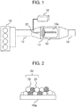
- FIG. 1 illustrates the outline of an exhaust gas control system for an internal combustion engine (which may be simply referred to as an "engine” hereinafter), the exhaust gas control system employing an exhaust gas catalyst according to the present invention.
- the exhaust gas control system shown in FIG. 1 includes an engine 10.
- the engine 10 is, for example, a straight-four engine.
- An exhaust pipe 12 is connected to the engine 10.
- a catalytic converter 14 is provided in the middle of the exhaust pipe 12.
- a honeycomb substrate 16 is provided inside the catalytic converter 14.
- the honeycomb substrate 16 is composed of, for example, cordierite (MgO-Al 2 O 3 -SiO 2 -based ceramic) or silicon carbide (SiC) or silicon nitride (Si 3 N 4 ) formed in a honeycomb shape.
- the exhaust gas catalyst is supported on the honeycomb substrate 16 (more precisely, on a rib 16a of the honeycomb substrate 16).
- An antenna 20 of a microwave oscillator 18 is provided upstream of the honeycomb substrate 16.
- the microwave oscillator 18 is configured to generate microwaves.
- the microwave oscillator 18 is, for example, a semiconductor oscillator.
- the microwave oscillator 18 may be configured with a magnetron, klystron, gyrotron, or the like.
- the antenna 20 is configured to emit microwaves toward the honeycomb substrate 16.
- the antenna 20 is, for example, a planar antenna, parabola antenna, or horn antenna.
- the frequency of the microwaves to be emitted is, for example, 2.45 GHz, 5.8 GHz, 24 GHz, or 915 MHz.
- the intensity of the microwaves to be emitted is not particularly limited.
- the microwave oscillator 18 is driven in response to a predetermined control signal, for example, during cold start of the engine 10. Once the microwave oscillator 18 is driven, microwaves emitted from the antenna 20 are applied to (incident on) the honeycomb substrate 16.
- the exhaust gas catalyst supported on the rib 16a absorbs the microwaves to generate heat and become hot.
- the exhaust gas catalyst is activated once the temperature of the catalyst reaches a predetermined temperature range. Consequently, it becomes possible to clean exhaust gas passing through the honeycomb substrate 16.
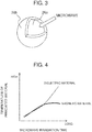
- FIG. 2 illustrates the outline of the configuration of the exhaust gas catalyst according to the present invention.
- an exhaust gas catalyst 22 is supported on the rib 16a.
- the exhaust gas catalyst 22 includes catalyst particles 24 and magnetic particles 26.
- the catalyst particles 24 exhibit the function of reducing the amount of a particular component contained in exhaust gas when the temperature of the catalyst particles 24 is in the activation temperature range as mentioned above.
- the magnetic particles 26 have approximately the same particle size as the catalyst particles 24.
- the magnetic particles 26 have the function of absorbing microwaves to generate heat. Once the magnetic particles 26 generate heat upon absorption of microwaves, the resulting thermal energy is emitted to the surroundings of the particles.
- the catalyst particles 24 placed around the magnetic particles 26 receive the thermal energy to become hot.
- the catalyst particles 24 are formed by supporting a noble metal such as platinum (Pt), palladium (Pd), or rhodium(Rh) on a porous ceramic.
- the porous ceramic is, for example, alumina (in particular ⁇ -alumina or 0-alumina) or zirconia (ZrO 2 ).
- cerium (Ce) may be further supported as an additive. Under a condition in which an air-fuel ratio is lean, cerium (Ce) is chemically combined with oxygen present in exhaust gas to form ceria (CeO 2 ), while under rich conditions, ceria (CeO 2 ) is partially reduced as a result of part of oxygen being released (2CeO 2 ⁇ Ce 2 O 3 + 1/2O 2 ). Due to the characteristics of cerium (Ce), the catalyst particles 24 adsorb oxygen from exhaust gas and store the oxygen under the condition in which the air-fuel ratio is lean. Under rich conditions, the catalyst particles 24 release the stored oxygen.
- a noble metal such as platinum (Pt
- the feature of the exhaust gas catalyst 22 lies in the structure of the magnetic particles 26.
- the magnetic particles 26 have a core-shell structure.
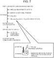
- FIG. 3 illustrates the structure of the magnetic particle 26.
- the magnetic particle 26 shown in FIG. 3 includes a core portion 26a and a shell portion 26b.
- the core portion 26a is composed of a powder of a ferromagnetic material.
- the shell portion 26b is provided to coat a surface of the powder of the ferromagnetic material.
- the ferromagnetic material composing the core portion 26a is a ferromagnetic oxide, a ferromagnetic metal, or a hexagonal ferrite.
- the ferromagnetic material may contain any one of these substances or may contain two or more of these substances.
- the ferromagnetic oxide is, for example, ⁇ -Fe 2 O 3 , Fe 3 O 4 , FeO x (1 ⁇ x ⁇ 1.5), Co-FeO x (1 ⁇ x ⁇ 1.5), Co-Fe 3 O 4 , or CrO 2 .
- the ferromagnetic metal is, for example, Fe, Fe-Co alloy, Fe-Pt, Fe 3 -Pt, Co-Pt, Fe 4 N, or Fe 5 C 2 .
- the outer surface of the ferromagnetic metal may include an oxide layer.
- the hexagonal ferrite is barium ferrite, strontium ferrite, lead ferrite, calcium ferrite, or a material resulting from substitution of any of these ferrites with Co or the like. More specific examples of the hexagonal ferrite include magnetoplumbite-type barium ferrite and strontium ferrite and magnetoplumbite-type barium ferrite and strontium ferrite partially containing a spinel phase.
- the coating material composing the shell portion 26b is, for example, a ceramic such as silicon nitride (Si 3 N 4 ), aluminum nitride (AlN), manganese oxide (Mn 3 O 4 ), or ⁇ -alumina or silica (SiO 2 ).
- the coating material may contain any one of these substances or may contain two or more of these substances.
- These ceramics and silica have a property of permitting passage of microwaves and are superior to ⁇ -alumina or ⁇ -alumina in a property of blocking gases (gas barrier property).
- these ceramics and silica have a property of permitting passage of microwaves while blocking passage of gases such as exhaust gas to a greater extent than ⁇ -alumina or ⁇ -alumina.
- ⁇ -alumina and silica have heat resistance and heat conductivity in addition to the above property.
- ⁇ -alumina and silica have high producibility and high poisoning resistance in addition to the above properties. It can therefore be considered that ⁇ -alumina and silica are particularly preferred as the coating material composing the shell portion 26b.
- Typical substances having the property of generating heat upon absorption of microwaves include dielectric materials and magnetic materials. Some dielectric materials have high durability. However, in the 2.45 GHz band which is the ISM band for microwaves, the wavelength of microwaves is around 12 cm, and there exist loops and nodes in microwave electric fields. Thus, it is difficult to cause a microwave electric field to act uniformly on a dielectric material. Additionally, dielectric materials have a property of becoming able to absorb microwaves to a greater extent with an increase in temperature. The use of a dielectric material is therefore likely to result in localization of the heat generating site, leading to uneven heating.
- FIG. 4 shows an example of the relationship between microwave irradiation time and the temperature of an irradiated material.
- the irradiated material is a dielectric material
- the temperature of the irradiated material increases with increasing irradiation time.
- the irradiated material is a magnetic material
- the temperature of the irradiated material converges toward a maximum temperature. This convergence temperature corresponds to the Curie temperature of the magnetic material.
- the Curie temperature can be adjusted depending on the material design of the magnetic material. Thus, when a magnetic material is designed to have a Curie temperature, the temperature of the whole magnetic material can be increased to the Curie temperature without uneven heating.
- FIG. 5 is a phase diagram of iron oxides which are main components of ferrites.
- the abscissa of FIG. 5 represents the oxygen content in the iron oxides.
- the ordinate represents the temperature of the atmosphere surrounding the iron oxides.
- iron(II, III) oxide exhibits the properties as a ferromagnetic material.
- the occurrence of the phase change of iron(II, III) oxide (Fe 3 O 4 ) entails a change in crystal structure.
- the change in crystal structure can occur when iron(II, III) oxide (Fe 3 O 4 ) is exposed to high-temperature exhaust gas (such as exhaust gas at 1000°C or higher) from an engine.
- iron(II, III) oxide (Fe 3 O 4 ) undergoes a chemical change (more precisely, iron(II, III) oxide (Fe 3 O 4 ) is subjected to a reducing action).
- the occurrence of the chemical change of iron(II, III) oxide (Fe 3 O 4 ) entails a change in molecular structure.
- iron(II, III) oxide (Fe 3 O 4 ) Under the condition in which the air-fuel ratio is lean, iron(II, III) oxide (Fe 3 O 4 ) is not subjected to any reducing action. Thus, under the condition in which the air-fuel ratio is lean, iron(II, III) oxide (Fe 3 O 4 ) undergoes only a phase change, so that a subsequent decrease in the temperature of the surrounding atmosphere can cause a phase change of iron(II) oxide (FeO) into iron(II, III) oxide (Fe 3 O 4 ). Under such a condition in which the air-fuel ratio is lean, however, iron(II, III) oxide (Fe 3 O 4 ) may be poisoned by a sulfur component or phosphorus component contained in the exhaust gas. The poisoning will result in the loss of the properties as a ferromagnetic material.
- Materials subject to influence on the above-described properties as a ferromagnetic material are not limited to iron(II, III) oxide (Fe 3 O 4 ) or ferrites containing iron(II, III) oxide (Fe 3 O 4 ) as a main component.
- iron(II, III) oxide Fe 3 O 4
- ferrites containing iron(II, III) oxide Fe 3 O 4
- CrO 2 chromium(IV) oxide
- CrO 2 which has the properties as a ferromagnetic material like iron(II, III) oxide (Fe 3 O 4 )
- the shell portion 26b is provided on a surface of a ferromagnetic material powder composing the core portion 26a.
- the coating material composing the shell portion 26b is superior to ⁇ -alumina or ⁇ -alumina in the property of blocking gases.
- FIG. 6 shows examples of the BET specific surface areas and pore volumes of ⁇ -alumina, ⁇ -alumina, ⁇ -alumina, and silica. As shown in FIG. 6 , ⁇ -alumina and silica have a smaller BET specific surface area than ⁇ -alumina and ⁇ -alumina. More specifically, the BET specific surface areas of ⁇ -alumina and silica are about 1/10 of the BET specific surface area of ⁇ -alumina. The pore volumes of ⁇ -alumina and silica are 1/30 or less of the pore volume of ⁇ -alumina.
- Having a small BET specific surface area and a small pore volume means being superior in the property of blocking gases.
- Being a coating material superior in the property of blocking gases means that the coating material, when used for the shell portion 26b, exhibits a high ability to inhibit gas communication between the core portion 26a and the outside environment.
- the configuration of the exhaust gas catalyst according to the present invention can achieve an increased resistance of the magnetic particles 26 to variation in exhaust gas conditions. Consequently, the warm-up effect based on the microwave absorption property of the magnetic particles 26 can last for a long period of time.
- FIG. 7 illustrates a first method for obtaining the exhaust gas catalyst according to the present invention.
- a surface of a ferromagnetic material is coated with silica.
- an aqueous nitric acid solution is added to distilled water to adjust the pH of the aqueous solution to 4.
- a powder of a ferromagnetic material e.g., a hexagonal ferrite
- a silica sol are added to the aqueous solution, which is stirred.
- Aqueous ammonia is then added to this aqueous solution to adjust the pH of the aqueous solution to 5 to 6.
- FIG. 7 it is shown how to adjust the pH of the aqueous solution.
- FIG. 8 shows an example of the relationship between the ⁇ potentials of the raw materials (the hexagonal ferrite and silica sol) and the pH of the aqueous solution.
- the silica sol having a negative ⁇ potential is attracted to the ferrite having a positive ⁇ potential.
- the subsequent adjustment of the pH of the aqueous solution to 5 and 6 creates a state in which the silica sol is adsorbed on the surface of the ferrite.
- Magnetic particles of a desired size can be obtained by appropriately varying the particle size of the ferrite, the concentration of the silica sol, or the time spent for the adjustment of the pH to 5 and 6.
- the raw materials in the adsorption state as shown are collected by filtration or centrifugation.
- the raw materials collected by filtration or centrifugation are then baked.
- magnetic particles are obtained.
- catalyst particles e.g., porous ceramic particles supporting a noble metal
- a binder is mixed with the obtained magnetic particles to prepare a slurry.
- the slurry is then supported on a honeycomb substrate. In this manner, the exhaust gas catalyst according to the present invention is obtained.
- FIG. 9 illustrates a second method for obtaining the exhaust gas catalyst according to the present invention.
- a surface of a ferromagnetic material is coated with silica.
- a powder of a ferromagnetic material e.g., a hexagonal ferrite
- a silane coupling agent e.g., vinyltriethoxysilane
- an organosilane e.g., tetramethylsilane
- the raw materials in the adsorption state as shown are collected by filtration or centrifugation.
- the raw materials collected by filtration or centrifugation are then baked to allow a dehydration condensation reaction of silanol to take place.
- magnetic particles are obtained.
- the procedures performed after the magnetic particles are obtained are the same as those in the method described with reference to FIG. 7 . In this manner, the exhaust gas catalyst according to the present invention is obtained.
- FIG. 10 illustrates a third method for obtaining the exhaust gas catalyst according to the present invention.
- a surface of a ferromagnetic material is coated with ⁇ -alumina.
- aluminum nitrate nonahydrate and a powder of a ferromagnetic material e.g., a hexagonal ferrite
- a ferromagnetic material e.g., a hexagonal ferrite
- aqueous ammonia e.g., a hexagonal ferrite
- FIG. 11 shows an example of the relationship of the ⁇ potentials of the raw materials (the hexagonal ferrite and boehmite) and the pH of the aqueous solution.
- the adjustment of the pH of the aqueous solution to 7 or higher results in formation of boehmite insoluble in the aqueous solution.
- the adjustment of the pH of the aqueous solution to 7 to 9 brings the ⁇ potential of the boehmite to a positive value and the ⁇ potential of the ferrite to a negative value. Consequently, the boehmite is attracted to the ferrite.
- On the right side of FIG. 10 is shown a state in which the boehmite is adsorbed on the surface of the ferrite.
- the raw materials in the adsorption state as shown are collected by filtration or centrifugation.
- the raw materials collected by filtration or centrifugation are then baked to allow a dehydration reaction of boehmite to take place.
- magnetic particles are obtained.
- the procedures performed after the magnetic particles are obtained are the same as those in the method described with reference to FIG. 7 . In this manner, the exhaust gas catalyst according to the present invention is obtained.
- FIG. 12 illustrates a fourth method for obtaining the exhaust gas catalyst according to the present invention.
- a surface of a ferromagnetic material is coated with ⁇ -alumina.
- a powder of a ferromagnetic material e.g., a hexagonal ferrite
- the resulting aqueous solution is heated to 80°C.
- aluminum nitrate nonahydrate is added to the aqueous solution, which is stirred.
- the amount of aluminum nitrate nonahydrate added corresponds to the saturation solubility.
- the aqueous solution is cooled to 40°C.
- FIG. 12 On the right side of FIG. 12 it is shown how aluminum hydrate is precipitated and adsorbed on the surface of the ferrite as a result of the decrease in temperature of the aqueous solution.
- the raw materials in the adsorption state as shown are collected by filtration or centrifugation.
- the raw materials collected by filtration or centrifugation are then baked to allow a dehydration reaction of the aluminum hydrate to take place.
- magnetic particles are obtained.
- the procedures performed after the magnetic particles are obtained are the same as those in the method described with reference to FIG. 7 . In this manner, the exhaust gas catalyst according to the present invention is obtained.
Landscapes
- Chemical & Material Sciences (AREA)
- Engineering & Computer Science (AREA)
- Chemical Kinetics & Catalysis (AREA)
- Health & Medical Sciences (AREA)
- Physics & Mathematics (AREA)
- Organic Chemistry (AREA)
- Combustion & Propulsion (AREA)
- Materials Engineering (AREA)
- Toxicology (AREA)
- Mechanical Engineering (AREA)
- General Engineering & Computer Science (AREA)
- Ceramic Engineering (AREA)
- Environmental & Geological Engineering (AREA)
- Analytical Chemistry (AREA)
- General Chemical & Material Sciences (AREA)
- Oil, Petroleum & Natural Gas (AREA)
- Biomedical Technology (AREA)
- Plasma & Fusion (AREA)
- Electromagnetism (AREA)
- Optics & Photonics (AREA)
- Thermal Sciences (AREA)
- Exhaust Gas Treatment By Means Of Catalyst (AREA)
- Catalysts (AREA)
- Exhaust Gas After Treatment (AREA)
- Power Engineering (AREA)
Abstract
An exhaust gas catalyst includes: catalyst particles (24) that clean exhaust gas; and magnetic particles (26) that are placed around the catalyst particles and that generate heat upon absorption of microwaves. Each of the magnetic particles includes: a core portion (26a) composed of a ferromagnetic material capable of generating heat upon absorption of microwaves; and a shell portion (26b) coating a surface of the core portion, the shell portion having a property of permitting passage of microwaves, the shell portion being superior to γ-alumina or θ-alumina in a property of blocking gases.
Description
- The present invention relates to exhaust gas catalysts for an internal combustion engine.
- Japanese Patent Application Publication No.
2016-187766 - Ferrites are generally composed of a multivalent element, and the valence of the element is readily changed due to variation in exhaust gas conditions. Specifically, under high-temperature conditions, magnetic materials undergo a phase change. The occurrence of a phase change of a ferrite means a change in the crystal structure of the ferrite. Under a condition in which an air-fuel ratio is in a range from a stoichiometric air-fuel ratio to a rich air-fuel ratio and a temperature is high, ferrites further undergo a chemical change. The occurrence of a chemical change of a ferrite means a change in the molecular structure of the ferrite. Under the condition in which the air-fuel ratio is in the range from the stoichiometric air-fuel ratio to the rich air-fuel ratio and the temperature is high, therefore, ferrites may undergo an irreversible change in the crystal structure or molecular structure and eventually deteriorate. By contrast, under a condition in which an air-fuel ratio is lean, change in the molecular structure of ferrites is slight. However, ferrites may be poisoned and deteriorated by a sulfur component or phosphorus component contained in the exhaust gas.
- In view of such deterioration of ferrites, the surface of the ferrite of the exhaust gas catalyst described above is coated with the catalyst layer (i.e., the support layer). However, γ-alumina and θ-alumina, either of which composes the support layer, have a high specific surface area. The high specific surface area implies the possibility that pores with a volume large enough to allow gas passage are present within these alumina. The presence of pores with such a volume causes exhaust gas around the exhaust gas catalyst to easily pass through the support layer to reach the ferrite. Thus, the occurrence of the above-described deterioration of the ferrite cannot be avoided, with the result that warm-up effect based on the microwave absorption property may be lost relatively early.
- The present invention has been made in view of the above problems and provides an exhaust gas catalyst that enables warm-up exploiting microwaves and that has high resistance to variation in exhaust gas conditions.
- An aspect of the present invention relates to an exhaust gas catalyst for an internal combustion engine, the exhaust gas catalyst including: catalyst particles that clean exhaust gas of the internal combustion engine; and magnetic particles that are placed around the catalyst particles and that generate heat upon absorption of microwaves, wherein each of the magnetic particles includes: a core portion composed of a ferromagnetic material capable of generating heat upon absorption of microwaves; and a shell portion coating a surface of the core portion, the shell portion having a property of permitting passage of microwaves, the shell portion being superior to γ-alumina or θ-alumina in a property of blocking gases.
- In the above aspect, the shell portion may be composed of at least one material of: i) silicon nitride; ii) aluminum nitride; iii) manganese oxide; iv) α-alumina; and v) silica.
- In the above aspect, the shell portion may be composed of at least one material of: i) α-alumina; and ii) silica.
- In the above aspect, a BET specific surface area of the shell portion may be less than 180 m2/g.
- In the above aspect, a BET specific surface area of the shell portion may be less than 105 m2/g.
- In the above aspect, a pore volume of the shell portion may be less than 0.7 cm2/g.
- In the above aspect, a pore volume of the shell portion may be less than 0.6 cm2/g.
- In the above aspect, the ferromagnetic material may include at least one material of: i) ferromagnetic oxide; ii) a ferromagnetic metal; and iii) a hexagonal ferrite.
- In the above aspect, the catalyst particles may include at least one material of: i) γ-alumina; ii) θ-alumina; and iii) zirconia.
- According to the present invention, magnetic particles each including a core portion composed of a ferromagnetic material and a shell portion coating the core portion are placed around catalyst particles. This shell portion has a property of permitting passage of microwaves. Thus, the temperature of the catalyst particles can be increased by heat generation of the core portion absorbing microwaves. Additionally, the shell portion is composed of silicon nitride, aluminum nitride, manganese oxide, α-alumina, or silica which is superior to γ-alumina or θ-alumina in a property of blocking gases. Thus, gas communication between the core portion and the outside environment can be decreased as compared to when a shell portion is composed of γ-alumina or θ-alumina. That is, entry of gas into the core portion from the outside environment and exit of gas from the core portion to the outside environment can be reduced. This can lead to an increase in the resistance of the magnetic particles to variation in exhaust gas conditions.
- Features, advantages, and technical and industrial significance of exemplary embodiments of the invention will be described below with reference to the accompanying drawings, in which like numerals denote like elements, and wherein:
-
FIG. 1 illustrates the outline of an exhaust gas control system for an internal combustion engine, the exhaust gas control system employing an exhaust gas catalyst according to the present invention; -
FIG. 2 illustrates the outline of the configuration of the exhaust gas catalyst according to the present invention; -
FIG. 3 illustrates the structure of a magnetic particle; -
FIG. 4 shows an example of the relationship between microwave irradiation time and the temperature of an irradiated material; -
FIG. 5 is a phase diagram of iron oxides; -
FIG. 6 shows examples of the BET specific surface areas and pore volumes of γ-alumina, θ-alumina, α-alumina, and silica; -
FIG. 7 illustrates a first method for obtaining the exhaust gas catalyst according to the present invention; -
FIG. 8 shows an example of the relationship between the ζ potentials of raw materials for the exhaust gas catalyst and the pH of an aqueous solution; -
FIG. 9 illustrates a second method for obtaining the exhaust gas catalyst according to the present invention; -
FIG. 10 illustrates a third method for obtaining the exhaust gas catalyst according to the present invention; -
FIG. 11 shows an example of the relationship between the ζ potentials of raw materials for the exhaust gas catalyst and the pH of an aqueous solution; and -
FIG. 12 illustrates a fourth method for obtaining the exhaust gas catalyst according to the present invention. - Hereinafter, embodiments of the present invention will be described with reference to the drawings. The same or equivalent components are denoted by the same reference signs in the figures, and the description of the components may be simplified or omitted.
-
FIG. 1 illustrates the outline of an exhaust gas control system for an internal combustion engine (which may be simply referred to as an "engine" hereinafter), the exhaust gas control system employing an exhaust gas catalyst according to the present invention. The exhaust gas control system shown inFIG. 1 includes anengine 10. Theengine 10 is, for example, a straight-four engine. Anexhaust pipe 12 is connected to theengine 10. In the middle of theexhaust pipe 12, acatalytic converter 14 is provided. Ahoneycomb substrate 16 is provided inside thecatalytic converter 14. Thehoneycomb substrate 16 is composed of, for example, cordierite (MgO-Al2O3-SiO2-based ceramic) or silicon carbide (SiC) or silicon nitride (Si3N4) formed in a honeycomb shape. The exhaust gas catalyst is supported on the honeycomb substrate 16 (more precisely, on arib 16a of the honeycomb substrate 16). - An
antenna 20 of amicrowave oscillator 18 is provided upstream of thehoneycomb substrate 16. Themicrowave oscillator 18 is configured to generate microwaves. Themicrowave oscillator 18 is, for example, a semiconductor oscillator. Themicrowave oscillator 18 may be configured with a magnetron, klystron, gyrotron, or the like. Theantenna 20 is configured to emit microwaves toward thehoneycomb substrate 16. Theantenna 20 is, for example, a planar antenna, parabola antenna, or horn antenna. The frequency of the microwaves to be emitted is, for example, 2.45 GHz, 5.8 GHz, 24 GHz, or 915 MHz. The intensity of the microwaves to be emitted is not particularly limited. - The
microwave oscillator 18 is driven in response to a predetermined control signal, for example, during cold start of theengine 10. Once themicrowave oscillator 18 is driven, microwaves emitted from theantenna 20 are applied to (incident on) thehoneycomb substrate 16. The exhaust gas catalyst supported on therib 16a absorbs the microwaves to generate heat and become hot. The exhaust gas catalyst is activated once the temperature of the catalyst reaches a predetermined temperature range. Consequently, it becomes possible to clean exhaust gas passing through thehoneycomb substrate 16. -
FIG. 2 illustrates the outline of the configuration of the exhaust gas catalyst according to the present invention. As shown inFIG. 2 , anexhaust gas catalyst 22 is supported on therib 16a. Theexhaust gas catalyst 22 includescatalyst particles 24 andmagnetic particles 26. Thecatalyst particles 24 exhibit the function of reducing the amount of a particular component contained in exhaust gas when the temperature of thecatalyst particles 24 is in the activation temperature range as mentioned above. Themagnetic particles 26 have approximately the same particle size as thecatalyst particles 24. Themagnetic particles 26 have the function of absorbing microwaves to generate heat. Once themagnetic particles 26 generate heat upon absorption of microwaves, the resulting thermal energy is emitted to the surroundings of the particles. Thecatalyst particles 24 placed around themagnetic particles 26 receive the thermal energy to become hot. - The
catalyst particles 24 are formed by supporting a noble metal such as platinum (Pt), palladium (Pd), or rhodium(Rh) on a porous ceramic. The porous ceramic is, for example, alumina (in particular γ-alumina or 0-alumina) or zirconia (ZrO2). In thecatalyst particles 24, cerium (Ce) may be further supported as an additive. Under a condition in which an air-fuel ratio is lean, cerium (Ce) is chemically combined with oxygen present in exhaust gas to form ceria (CeO2), while under rich conditions, ceria (CeO2) is partially reduced as a result of part of oxygen being released (2CeO2→Ce2O3 + 1/2O2). Due to the characteristics of cerium (Ce), thecatalyst particles 24 adsorb oxygen from exhaust gas and store the oxygen under the condition in which the air-fuel ratio is lean. Under rich conditions, thecatalyst particles 24 release the stored oxygen. - The feature of the
exhaust gas catalyst 22 lies in the structure of themagnetic particles 26. Specifically, themagnetic particles 26 have a core-shell structure. -
FIG. 3 illustrates the structure of themagnetic particle 26. Themagnetic particle 26 shown inFIG. 3 includes acore portion 26a and ashell portion 26b. Thecore portion 26a is composed of a powder of a ferromagnetic material. Theshell portion 26b is provided to coat a surface of the powder of the ferromagnetic material. - The ferromagnetic material composing the
core portion 26a is a ferromagnetic oxide, a ferromagnetic metal, or a hexagonal ferrite. The ferromagnetic material may contain any one of these substances or may contain two or more of these substances. The ferromagnetic oxide is, for example, γ-Fe2O3, Fe3O4, FeOx(1≤ x ≤ 1.5), Co-FeOx (1 ≤ x ≤ 1.5), Co-Fe3O4, or CrO2. The ferromagnetic metal is, for example, Fe, Fe-Co alloy, Fe-Pt, Fe3-Pt, Co-Pt, Fe4N, or Fe5C2. The outer surface of the ferromagnetic metal may include an oxide layer. The hexagonal ferrite is barium ferrite, strontium ferrite, lead ferrite, calcium ferrite, or a material resulting from substitution of any of these ferrites with Co or the like. More specific examples of the hexagonal ferrite include magnetoplumbite-type barium ferrite and strontium ferrite and magnetoplumbite-type barium ferrite and strontium ferrite partially containing a spinel phase. - The coating material composing the
shell portion 26b is, for example, a ceramic such as silicon nitride (Si3N4), aluminum nitride (AlN), manganese oxide (Mn3O4), or α-alumina or silica (SiO2). The coating material may contain any one of these substances or may contain two or more of these substances. These ceramics and silica have a property of permitting passage of microwaves and are superior to γ-alumina or θ-alumina in a property of blocking gases (gas barrier property). Thus, these ceramics and silica have a property of permitting passage of microwaves while blocking passage of gases such as exhaust gas to a greater extent than γ-alumina or θ-alumina. These ceramics and silica have heat resistance and heat conductivity in addition to the above property. α-alumina and silica have high producibility and high poisoning resistance in addition to the above properties. It can therefore be considered that α-alumina and silica are particularly preferred as the coating material composing theshell portion 26b. - Typical substances having the property of generating heat upon absorption of microwaves include dielectric materials and magnetic materials. Some dielectric materials have high durability. However, in the 2.45 GHz band which is the ISM band for microwaves, the wavelength of microwaves is around 12 cm, and there exist loops and nodes in microwave electric fields. Thus, it is difficult to cause a microwave electric field to act uniformly on a dielectric material. Additionally, dielectric materials have a property of becoming able to absorb microwaves to a greater extent with an increase in temperature. The use of a dielectric material is therefore likely to result in localization of the heat generating site, leading to uneven heating.
- Magnetic materials have a property of ceasing to exhibit magnetism at a temperature equal to or higher than the Curie temperature. Thus, once the temperature of a magnetic material increases beyond the Curie temperature, the magnetic material becomes insensitive to the action of microwaves.
FIG. 4 shows an example of the relationship between microwave irradiation time and the temperature of an irradiated material. When the irradiated material is a dielectric material, the temperature of the irradiated material increases with increasing irradiation time. When the irradiated material is a magnetic material, the temperature of the irradiated material converges toward a maximum temperature. This convergence temperature corresponds to the Curie temperature of the magnetic material. The Curie temperature can be adjusted depending on the material design of the magnetic material. Thus, when a magnetic material is designed to have a Curie temperature, the temperature of the whole magnetic material can be increased to the Curie temperature without uneven heating. - Furthermore, when a magnetic material is designed to have a Curie temperature within the activation temperature range mentioned above, not only the temperature of the magnetic material but also the temperature of a substance placed around the magnetic material can be increased to the Curie temperature. As previously stated, however, ferrites can deteriorate due to variation in exhaust gas conditions. This deterioration will be described with reference to
FIG. 5. FIG. 5 is a phase diagram of iron oxides which are main components of ferrites. The abscissa ofFIG. 5 represents the oxygen content in the iron oxides. The ordinate represents the temperature of the atmosphere surrounding the iron oxides. Among the three iron oxides shown inFIG. 5 , iron(II, III) oxide (Fe3O4) exhibits the properties as a ferromagnetic material. - As indicated by an arrow in the center of
FIG. 5 , iron(II, III) oxide (Fe3O4) having an oxygen content of 20% or less undergoes a phase change into iron(II) oxide (FeO) once the temperature of the surrounding atmosphere rises beyond about 570°C. The occurrence of the phase change of iron(II, III) oxide (Fe3O4) entails a change in crystal structure. The change in crystal structure can occur when iron(II, III) oxide (Fe3O4) is exposed to high-temperature exhaust gas (such as exhaust gas at 1000°C or higher) from an engine. Under a condition in which an air-fuel ratio is in a range from a stoichiometric air-fuel ratio to a rich air-fuel ratio, iron(II, III) oxide (Fe3O4) undergoes a chemical change (more precisely, iron(II, III) oxide (Fe3O4) is subjected to a reducing action). The occurrence of the chemical change of iron(II, III) oxide (Fe3O4) entails a change in molecular structure. Thus, under a condition in which the air-fuel ratio is in the range from the stoichiometric air-fuel ratio to the rich air-fuel ratio and the temperature is high, a phase change and chemical change of iron(II, III) oxide (Fe3O4) occur concomitantly, so that iron(II, III) oxide (Fe3O4) can no longer exist. This results in the loss of the properties as a ferromagnetic material. - If a phase change into iron(II) oxide (FeO) occurs alone and then the temperature of the atmosphere surrounding iron(II) oxide (FeO) decreases, a phase change may occur in a direction opposite to the direction of the arrow shown in
FIG. 5 to cause reconversion to iron(II, III) oxide (Fe3O4). However, when a phase change and chemical change of iron(II, III) oxide (Fe3O4) occur concomitantly, iron(II) oxide (FeO) is unlikely to be reconverted to iron(II, III) oxide (Fe3O4) even if the temperature of the atmosphere surrounding iron(II) oxide (FeO) decreases. This is because reconversion to iron(II, III) oxide (Fe3O4) is impossible at least unless under the condition in which the air-fuel ratio is lean (namely, unless oxygen exists around iron(II) oxide (FeO)). Thus, once iron(II, III) oxide (Fe3O4) is converted to iron(II) oxide (FeO) under the condition in which the air-fuel ratio is in the range from the stoichiometric air-fuel ratio to the rich air-fuel ratio and the temperature is high, it is difficult to restore the properties as a ferromagnetic material even if the temperature of the atmosphere surrounding iron(II) oxide (FeO) subsequently decreases. - Under the condition in which the air-fuel ratio is lean, iron(II, III) oxide (Fe3O4) is not subjected to any reducing action. Thus, under the condition in which the air-fuel ratio is lean, iron(II, III) oxide (Fe3O4) undergoes only a phase change, so that a subsequent decrease in the temperature of the surrounding atmosphere can cause a phase change of iron(II) oxide (FeO) into iron(II, III) oxide (Fe3O4). Under such a condition in which the air-fuel ratio is lean, however, iron(II, III) oxide (Fe3O4) may be poisoned by a sulfur component or phosphorus component contained in the exhaust gas. The poisoning will result in the loss of the properties as a ferromagnetic material.
- Materials subject to influence on the above-described properties as a ferromagnetic material are not limited to iron(II, III) oxide (Fe3O4) or ferrites containing iron(II, III) oxide (Fe3O4) as a main component. For example, chromium(IV) oxide (CrO2), which has the properties as a ferromagnetic material like iron(II, III) oxide (Fe3O4), can lose the properties as a ferromagnetic material by undergoing a phase change into chromium(III) oxide (Cr2O3). Additionally, under the condition in which the air-fuel ratio is in the range from the stoichiometric air-fuel ratio to the rich air-fuel ratio and the temperature is high, chromium(IV) oxide (CrO2) is reduced and converted to chromium(III) oxide (Cr2O3). Thus, the ferromagnetic oxides and ferromagnetic metals as mentioned above have the same disadvantage as iron(II, III) oxide (Fe3O4) described with reference to
FIG. 5 . - In the exhaust gas catalyst according to the present invention, the
shell portion 26b is provided on a surface of a ferromagnetic material powder composing thecore portion 26a. The coating material composing theshell portion 26b is superior to γ-alumina or θ-alumina in the property of blocking gases.FIG. 6 shows examples of the BET specific surface areas and pore volumes of γ-alumina, θ-alumina, α-alumina, and silica. As shown inFIG. 6 , α-alumina and silica have a smaller BET specific surface area than γ-alumina and θ-alumina. More specifically, the BET specific surface areas of α-alumina and silica are about 1/10 of the BET specific surface area of γ-alumina. The pore volumes of α-alumina and silica are 1/30 or less of the pore volume of γ-alumina. - Having a small BET specific surface area and a small pore volume means being superior in the property of blocking gases. Being a coating material superior in the property of blocking gases means that the coating material, when used for the
shell portion 26b, exhibits a high ability to inhibit gas communication between thecore portion 26a and the outside environment. Thus, even under the condition in which the air-fuel ratio is in the range from the stoichiometric air-fuel ratio to the rich air-fuel ratio and the temperature is high, the influence of reducing components present in the exhaust gas can be diminished. Consequently, it is possible to decrease the extent to which the ferromagnetic material in thecore portion 26a is subjected to a reducing action. In addition, under the condition in which the air-fuel ratio is lean, the influence of poisoning components present in the exhaust gas can be diminished. - Furthermore, even when the temperature of the atmosphere surrounding the
magnetic particles 26 increases to induce a phase change which entails release of oxygen from the crystal structure composing thecore portion 26a, the released oxygen can be retained inside theshell portion 26b. Thus, after a decrease in the temperature of the atmosphere surrounding themagnetic particles 26, thecore portion 26a can incorporate the released oxygen into the crystal structure to regain the properties as a ferromagnetic material. For these reasons, the configuration of the exhaust gas catalyst according to the present invention can achieve an increased resistance of themagnetic particles 26 to variation in exhaust gas conditions. Consequently, the warm-up effect based on the microwave absorption property of themagnetic particles 26 can last for a long period of time. -
FIG. 7 illustrates a first method for obtaining the exhaust gas catalyst according to the present invention. In the method illustrated inFIG. 7 , a surface of a ferromagnetic material is coated with silica. In the method illustrated inFIG. 7 , first, an aqueous nitric acid solution is added to distilled water to adjust the pH of the aqueous solution to 4. Subsequently, a powder of a ferromagnetic material (e.g., a hexagonal ferrite) and a silica sol are added to the aqueous solution, which is stirred. Aqueous ammonia is then added to this aqueous solution to adjust the pH of the aqueous solution to 5 to 6. On the right side ofFIG. 7 it is shown how to adjust the pH of the aqueous solution. -
FIG. 8 shows an example of the relationship between the ζ potentials of the raw materials (the hexagonal ferrite and silica sol) and the pH of the aqueous solution. As shown inFIG. 8 , upon the addition of the raw materials to the aqueous solution having a pH of about 4, the silica sol having a negative ζ potential is attracted to the ferrite having a positive ζ potential. The subsequent adjustment of the pH of the aqueous solution to 5 and 6 creates a state in which the silica sol is adsorbed on the surface of the ferrite. Magnetic particles of a desired size can be obtained by appropriately varying the particle size of the ferrite, the concentration of the silica sol, or the time spent for the adjustment of the pH to 5 and 6. - In the method illustrated in
FIG. 7 , the raw materials in the adsorption state as shown are collected by filtration or centrifugation. The raw materials collected by filtration or centrifugation are then baked. As a result, magnetic particles are obtained. Subsequently, catalyst particles (e.g., porous ceramic particles supporting a noble metal) adjusted to a desired size beforehand and a binder are mixed with the obtained magnetic particles to prepare a slurry. The slurry is then supported on a honeycomb substrate. In this manner, the exhaust gas catalyst according to the present invention is obtained. -
FIG. 9 illustrates a second method for obtaining the exhaust gas catalyst according to the present invention. In the method illustrated inFIG. 9 , a surface of a ferromagnetic material is coated with silica. In the method illustrated inFIG. 9 , first, a powder of a ferromagnetic material (e.g., a hexagonal ferrite), a silane coupling agent (e.g., vinyltriethoxysilane), and an organosilane (e.g., tetramethylsilane) are added to ethanol, and the mixture is stirred. To the resulting ethanol solution are then added an aqueous nitric acid solution or aqueous ammonia. This allows a hydrolysis reaction to take place so as to create a state in which silanol is adsorbed on the surface of the powder of the ferromagnetic material. On the right side ofFIG. 9 is shown the outline of the process in which a silanol oligomer is finally adsorbed on the surface of the ferromagnetic material in a hydrogen-bonding fashion. - In the method illustrated in
FIG. 9 , the raw materials in the adsorption state as shown are collected by filtration or centrifugation. The raw materials collected by filtration or centrifugation are then baked to allow a dehydration condensation reaction of silanol to take place. As a result, magnetic particles are obtained. The procedures performed after the magnetic particles are obtained are the same as those in the method described with reference toFIG. 7 . In this manner, the exhaust gas catalyst according to the present invention is obtained. -
FIG. 10 illustrates a third method for obtaining the exhaust gas catalyst according to the present invention. In the method illustrated inFIG. 10 , a surface of a ferromagnetic material is coated with α-alumina. In the method illustrated inFIG. 10 , first, aluminum nitrate nonahydrate and a powder of a ferromagnetic material (e.g., a hexagonal ferrite) are added to distilled water, and the mixture is stirred. To the resulting aqueous solution is then added aqueous ammonia to adjust the pH of the aqueous solution to 7 to 9. On the right side ofFIG. 10 it is shown how aluminum hydrate (boehmite) is precipitated as a result of the adjustment of the pH of the aqueous solution. -
FIG. 11 shows an example of the relationship of the ζ potentials of the raw materials (the hexagonal ferrite and boehmite) and the pH of the aqueous solution. As shown inFIG. 11 , the adjustment of the pH of the aqueous solution to 7 or higher results in formation of boehmite insoluble in the aqueous solution. The adjustment of the pH of the aqueous solution to 7 to 9 brings the ζ potential of the boehmite to a positive value and the ζ potential of the ferrite to a negative value. Consequently, the boehmite is attracted to the ferrite. On the right side ofFIG. 10 is shown a state in which the boehmite is adsorbed on the surface of the ferrite. - In the method illustrated in
FIG. 10 , the raw materials in the adsorption state as shown are collected by filtration or centrifugation. The raw materials collected by filtration or centrifugation are then baked to allow a dehydration reaction of boehmite to take place. As a result, magnetic particles are obtained. The procedures performed after the magnetic particles are obtained are the same as those in the method described with reference toFIG. 7 . In this manner, the exhaust gas catalyst according to the present invention is obtained. -
FIG. 12 illustrates a fourth method for obtaining the exhaust gas catalyst according to the present invention. In the method illustrated inFIG. 12 , a surface of a ferromagnetic material is coated with α-alumina. In the method illustrated inFIG. 12 , first, a powder of a ferromagnetic material (e.g., a hexagonal ferrite) is added to distilled water, and the mixture is stirred. Subsequently, the resulting aqueous solution is heated to 80°C. Once the temperature of the aqueous solution reaches 80°C, aluminum nitrate nonahydrate is added to the aqueous solution, which is stirred. The amount of aluminum nitrate nonahydrate added corresponds to the saturation solubility. Subsequently, the aqueous solution is cooled to 40°C. On the right side ofFIG. 12 it is shown how aluminum hydrate is precipitated and adsorbed on the surface of the ferrite as a result of the decrease in temperature of the aqueous solution. - In the method illustrated in
FIG. 12 , the raw materials in the adsorption state as shown are collected by filtration or centrifugation. The raw materials collected by filtration or centrifugation are then baked to allow a dehydration reaction of the aluminum hydrate to take place. As a result, magnetic particles are obtained. The procedures performed after the magnetic particles are obtained are the same as those in the method described with reference toFIG. 7 . In this manner, the exhaust gas catalyst according to the present invention is obtained. - Although numerical values indicating the number, numerical quantity, amount, or range may be presented for the elements of the foregoing embodiment, the present invention is not limited to the presented numerical values unless otherwise explicitly stated or unless it is clear that the numerical values should be employed in principle. The structures etc. described for the foregoing embodiment are not necessarily essential for the invention unless otherwise explicitly stated or unless it is clear that such structures etc. should be employed in principle.
Claims (9)
- An exhaust gas catalyst for an internal combustion engine, comprising:catalyst particles (24) that clean exhaust gas of the internal combustion engine; andmagnetic particles (26) that are placed around the catalyst particles and that generate heat upon absorption of microwaves, wherein each of the magnetic particles includes:a core portion (26a) composed of a ferromagnetic material capable of generating heat upon absorption of microwaves; anda shell portion (26b) coating a surface of the core portion, the shell portion having a property of permitting passage of microwaves, the shell portion being superior to γ-alumina or θ-alumina in a property of blocking gases.
- The exhaust gas catalyst according to claim 1, wherein the shell portion (26b) is composed of at least one material of: i) silicon nitride; ii) aluminum nitride; iii) manganese oxide; iv) α-alumina; and v) silica.
- The exhaust gas catalyst according to claim 1, wherein the shell portion (26b) is composed of at least one material of: i) α-alumina; and ii) silica.
- The exhaust gas catalyst according to any one of claims 1 to 3, wherein a BET specific surface area of the shell portion (26b) is less than 180 m2/g.
- The exhaust gas catalyst according to any one of claims 1 to 3, wherein a BET specific surface area of the shell portion (26b) is less than 105 m2/g.
- The exhaust gas catalyst according to any one of claims 1 to 5, wherein a pore volume of the shell portion (26b) is less than 0.7 cm2/g.
- The exhaust gas catalyst according to any one of claims 1 to 5, wherein a pore volume of the shell portion (26b) is less than 0.6 cm2/g.
- The exhaust gas catalyst according to any one of claims 1 to 7, wherein the ferromagnetic material includes at least one material of: i) ferromagnetic oxide; ii) a ferromagnetic metal; and iii) a hexagonal ferrite.
- The exhaust gas catalyst according to any one of claims 1 to 8, wherein the catalyst particles (24) include at least one material of: i) γ-alumina; ii) θ-alumina; and iii) zirconia.
Applications Claiming Priority (1)
| Application Number | Priority Date | Filing Date | Title |
|---|---|---|---|
| JP2017235077A JP2019098292A (en) | 2017-12-07 | 2017-12-07 | Exhaust gas purification catalyst of internal combustion engine |
Publications (1)
| Publication Number | Publication Date |
|---|---|
| EP3495635A1 true EP3495635A1 (en) | 2019-06-12 |
Family
ID=63861981
Family Applications (1)
| Application Number | Title | Priority Date | Filing Date |
|---|---|---|---|
| EP18197953.5A Withdrawn EP3495635A1 (en) | 2017-12-07 | 2018-10-01 | Exhaust gas catalyst for internal combustion engines |
Country Status (5)
| Country | Link |
|---|---|
| US (1) | US20190176140A1 (en) |
| EP (1) | EP3495635A1 (en) |
| JP (1) | JP2019098292A (en) |
| KR (1) | KR20190068410A (en) |
| BR (1) | BR102018071767A2 (en) |
Cited By (2)
| Publication number | Priority date | Publication date | Assignee | Title |
|---|---|---|---|---|
| EP3714964A1 (en) * | 2019-03-28 | 2020-09-30 | Johnson Matthey Public Limited Company | An exhaust gas treatment system and the use thereof for the treatment of an exhaust gas |
| WO2020254184A1 (en) * | 2019-06-20 | 2020-12-24 | Haldor Topsøe A/S | Ferromagnetic catalyst support for induction heated catalysis |
Citations (5)
| Publication number | Priority date | Publication date | Assignee | Title |
|---|---|---|---|---|
| JPH05168950A (en) * | 1991-12-17 | 1993-07-02 | Zexel Corp | Combustion exhaust gas purification catalyst |
| JP2006055798A (en) * | 2004-08-23 | 2006-03-02 | Toyota Motor Corp | Exhaust gas purification catalyst |
| JP2006057584A (en) * | 2004-08-23 | 2006-03-02 | Toyota Motor Corp | Exhaust gas purification catalyst |
| WO2011150129A2 (en) * | 2010-05-25 | 2011-12-01 | Intercat, Inc. | Cracking catalyst, additives, methods of making them and using them |
| JP2016187766A (en) | 2015-03-30 | 2016-11-04 | 日本特殊陶業株式会社 | Microwave heating catalyst material and microwave heating catalyst body |
Family Cites Families (15)
| Publication number | Priority date | Publication date | Assignee | Title |
|---|---|---|---|---|
| GB0200260D0 (en) * | 2002-01-07 | 2002-02-20 | Inst Of Applied Catalysis The | Microparticles and methods of making them |
| US20060102871A1 (en) * | 2003-04-08 | 2006-05-18 | Xingwu Wang | Novel composition |
| JP4530003B2 (en) * | 2007-07-12 | 2010-08-25 | トヨタ自動車株式会社 | Fuel cell electrode catalyst and solid polymer fuel cell using the same |
| US20130105397A1 (en) * | 2010-01-12 | 2013-05-02 | Council Of Scientific & Industrial Research | Magnetic dye-adsorbent catalyst |
| WO2011108162A1 (en) * | 2010-03-01 | 2011-09-09 | 株式会社ノリタケカンパニーリミテド | Catalyst having metal microparticles supported thereon, and use thereof |
| JPWO2011125195A1 (en) * | 2010-04-07 | 2013-07-08 | トヨタ自動車株式会社 | Core-shell type metal nanoparticles and method for producing core-shell type metal nanoparticles |
| DE112010005462T5 (en) * | 2010-04-07 | 2013-03-14 | Toyota Jidosha Kabushiki Kaisha | Core-shell metal nanoparticles and process for their preparation |
| WO2011125196A1 (en) * | 2010-04-07 | 2011-10-13 | トヨタ自動車株式会社 | Fuel cell |
| JP5573438B2 (en) * | 2010-07-09 | 2014-08-20 | トヨタ自動車株式会社 | Method for producing core-shell type catalyst fine particles |
| WO2012132757A1 (en) * | 2011-03-30 | 2012-10-04 | 国立大学法人名古屋工業大学 | Skeleton nanoparticles and method for producing same |
| WO2014073114A1 (en) * | 2012-11-07 | 2014-05-15 | Toyota Jidosha Kabushiki Kaisha | Method for producing a catalyst for fuel cells |
| WO2014188448A1 (en) * | 2013-05-24 | 2014-11-27 | Council Of Scientific & Industrial Research | Semiconductor-oxides nanotubes-based composite particles useful for dye-removal and process thereof |
| WO2016060367A1 (en) * | 2014-10-17 | 2016-04-21 | 한국에너지기술연구원 | Egg-shell-type highly dispersed nanoparticle-metal oxide support hybrid structure, method for preparing same, and use thereof |
| US9868087B2 (en) * | 2016-03-31 | 2018-01-16 | Toyota Jidosha Kabushiki Kaisha | Core-shell oxide material, method for producing the same, and catalyst and method for purification of exhaust gas using the core-shell oxide material |
| US20180318802A1 (en) * | 2017-05-03 | 2018-11-08 | James Dorman | Catalytic reaction |
-
2017
- 2017-12-07 JP JP2017235077A patent/JP2019098292A/en active Pending
-
2018
- 2018-09-26 US US15/929,050 patent/US20190176140A1/en not_active Abandoned
- 2018-10-01 EP EP18197953.5A patent/EP3495635A1/en not_active Withdrawn
- 2018-10-01 KR KR1020180116815A patent/KR20190068410A/en not_active Ceased
- 2018-10-23 BR BR102018071767-7A patent/BR102018071767A2/en not_active IP Right Cessation
Patent Citations (5)
| Publication number | Priority date | Publication date | Assignee | Title |
|---|---|---|---|---|
| JPH05168950A (en) * | 1991-12-17 | 1993-07-02 | Zexel Corp | Combustion exhaust gas purification catalyst |
| JP2006055798A (en) * | 2004-08-23 | 2006-03-02 | Toyota Motor Corp | Exhaust gas purification catalyst |
| JP2006057584A (en) * | 2004-08-23 | 2006-03-02 | Toyota Motor Corp | Exhaust gas purification catalyst |
| WO2011150129A2 (en) * | 2010-05-25 | 2011-12-01 | Intercat, Inc. | Cracking catalyst, additives, methods of making them and using them |
| JP2016187766A (en) | 2015-03-30 | 2016-11-04 | 日本特殊陶業株式会社 | Microwave heating catalyst material and microwave heating catalyst body |
Cited By (4)
| Publication number | Priority date | Publication date | Assignee | Title |
|---|---|---|---|---|
| EP3714964A1 (en) * | 2019-03-28 | 2020-09-30 | Johnson Matthey Public Limited Company | An exhaust gas treatment system and the use thereof for the treatment of an exhaust gas |
| WO2020194252A1 (en) * | 2019-03-28 | 2020-10-01 | Johnson Matthey Public Limited Company | An exhaust gas treatment system and the use thereof for the treatment of an exhaust gas |
| US11187126B2 (en) | 2019-03-28 | 2021-11-30 | Johnson Matthey Public Limited Company | Exhaust gas treatment system and the use thereof for the treatment of an exhaust gas |
| WO2020254184A1 (en) * | 2019-06-20 | 2020-12-24 | Haldor Topsøe A/S | Ferromagnetic catalyst support for induction heated catalysis |
Also Published As
| Publication number | Publication date |
|---|---|
| JP2019098292A (en) | 2019-06-24 |
| KR20190068410A (en) | 2019-06-18 |
| BR102018071767A2 (en) | 2019-09-17 |
| US20190176140A1 (en) | 2019-06-13 |
Similar Documents
| Publication | Publication Date | Title |
|---|---|---|
| JP5361855B2 (en) | Palladium-rhodium single layer catalyst | |
| EP3103977B1 (en) | Exhaust gas control system for internal combustion engine | |
| CN1972752B (en) | Metal oxide particle, process for producing the same, and exhaust gas purifying catalyst | |
| EP3708541B1 (en) | Oxygen absorbing and releasing material, catalyst, exhaust gas purifying system, and exhaust gas treatment method | |
| JP6438819B2 (en) | Microwave heating catalyst material, method for producing the same, and microwave heating catalyst body | |
| US20190093531A1 (en) | Exhaust gas purification catalyst | |
| JPH0243951A (en) | Catalyst for purifying exhaust gas and preparation thereof | |
| CN105307769A (en) | Integrated supports for emission control catalysts | |
| WO2022076335A1 (en) | Catalyst composition comprising ferrite-based magnetic material adapted for inductive heating | |
| WO2015182726A9 (en) | Catalyst for internal combustion engine exhaust gas purification, and system for same | |
| US8629078B2 (en) | Composite oxide for exhaust gas purifying catalyst and exhaust gas purifying catalyst, and diesel exhaust gas purifying filter | |
| CN107206360A (en) | Three-way catalyst | |
| JP7078521B2 (en) | Exhaust gas purification catalyst | |
| EP3495635A1 (en) | Exhaust gas catalyst for internal combustion engines | |
| JP2007512133A (en) | Catalyst for diesel particulate filter | |
| KR20140011312A (en) | Denitration catalyst composition and method of denitration using same | |
| CN102958608A (en) | Catalyst for purifying exhaust gas and method for producing the same | |
| JP4666006B2 (en) | Exhaust gas purification catalyst | |
| US10975744B2 (en) | Exhaust gas purification apparatus for motor vehicles | |
| CN105517704A (en) | Exhaust gas purification catalyst for motor vehicles | |
| CN106457226B (en) | Catalyst for exhaust gas purification | |
| JPH05168950A (en) | Combustion exhaust gas purification catalyst | |
| JP2013059759A (en) | Catalyst for burning particulate matter | |
| JPH10288027A (en) | High frequency heating catalyst | |
| US12257573B2 (en) | Multifunctional catalyst for hydrocarbon oxidation and selective catalytic reduction of NOx |
Legal Events
| Date | Code | Title | Description |
|---|---|---|---|
| PUAI | Public reference made under article 153(3) epc to a published international application that has entered the european phase |
Free format text: ORIGINAL CODE: 0009012 |
|
| STAA | Information on the status of an ep patent application or granted ep patent |
Free format text: STATUS: REQUEST FOR EXAMINATION WAS MADE |
|
| 17P | Request for examination filed |
Effective date: 20181101 |
|
| AK | Designated contracting states |
Kind code of ref document: A1 Designated state(s): AL AT BE BG CH CY CZ DE DK EE ES FI FR GB GR HR HU IE IS IT LI LT LU LV MC MK MT NL NO PL PT RO RS SE SI SK SM TR |
|
| AX | Request for extension of the european patent |
Extension state: BA ME |
|
| STAA | Information on the status of an ep patent application or granted ep patent |
Free format text: STATUS: THE APPLICATION IS DEEMED TO BE WITHDRAWN |
|
| 18D | Application deemed to be withdrawn |
Effective date: 20191213 |