EP3495622A1 - Aerofoil, corresponding assembly and methods of manufacturing - Google Patents
Aerofoil, corresponding assembly and methods of manufacturing Download PDFInfo
- Publication number
- EP3495622A1 EP3495622A1 EP18207140.7A EP18207140A EP3495622A1 EP 3495622 A1 EP3495622 A1 EP 3495622A1 EP 18207140 A EP18207140 A EP 18207140A EP 3495622 A1 EP3495622 A1 EP 3495622A1
- Authority
- EP
- European Patent Office
- Prior art keywords
- face
- aerofoil
- angled
- platform
- component
- Prior art date
- Legal status (The legal status is an assumption and is not a legal conclusion. Google has not performed a legal analysis and makes no representation as to the accuracy of the status listed.)
- Withdrawn
Links
- 238000004519 manufacturing process Methods 0.000 title claims description 10
- 238000000034 method Methods 0.000 title claims description 8
- 238000007789 sealing Methods 0.000 claims abstract description 49
- 238000005266 casting Methods 0.000 claims abstract description 13
- 238000005304 joining Methods 0.000 claims abstract description 7
- 239000012720 thermal barrier coating Substances 0.000 claims description 13
- 229910052751 metal Inorganic materials 0.000 claims description 11
- 239000002184 metal Substances 0.000 claims description 11
- 239000000463 material Substances 0.000 claims description 9
- 238000010926 purge Methods 0.000 description 17
- 238000001816 cooling Methods 0.000 description 16
- 239000011248 coating agent Substances 0.000 description 9
- 238000000576 coating method Methods 0.000 description 9
- 238000003754 machining Methods 0.000 description 6
- 230000002411 adverse Effects 0.000 description 4
- 238000002485 combustion reaction Methods 0.000 description 4
- BASFCYQUMIYNBI-UHFFFAOYSA-N platinum Chemical compound [Pt] BASFCYQUMIYNBI-UHFFFAOYSA-N 0.000 description 4
- 230000001141 propulsive effect Effects 0.000 description 4
- 238000005507 spraying Methods 0.000 description 4
- 229910001338 liquidmetal Inorganic materials 0.000 description 3
- 238000003801 milling Methods 0.000 description 3
- 230000008859 change Effects 0.000 description 2
- 230000006835 compression Effects 0.000 description 2
- 238000007906 compression Methods 0.000 description 2
- 230000007423 decrease Effects 0.000 description 2
- 230000000694 effects Effects 0.000 description 2
- 238000005562 fading Methods 0.000 description 2
- 229910052697 platinum Inorganic materials 0.000 description 2
- 230000008569 process Effects 0.000 description 2
- 229910001233 yttria-stabilized zirconia Inorganic materials 0.000 description 2
- 229910000951 Aluminide Inorganic materials 0.000 description 1
- 239000004411 aluminium Substances 0.000 description 1
- 229910052782 aluminium Inorganic materials 0.000 description 1
- XAGFODPZIPBFFR-UHFFFAOYSA-N aluminium Chemical compound [Al] XAGFODPZIPBFFR-UHFFFAOYSA-N 0.000 description 1
- 230000008901 benefit Effects 0.000 description 1
- 239000002826 coolant Substances 0.000 description 1
- 238000005553 drilling Methods 0.000 description 1
- 238000009760 electrical discharge machining Methods 0.000 description 1
- 239000000446 fuel Substances 0.000 description 1
- 238000000227 grinding Methods 0.000 description 1
- 238000002844 melting Methods 0.000 description 1
- 230000008018 melting Effects 0.000 description 1
- 239000000203 mixture Substances 0.000 description 1
- 238000012986 modification Methods 0.000 description 1
- 230000004048 modification Effects 0.000 description 1
- 238000013021 overheating Methods 0.000 description 1
- 230000003647 oxidation Effects 0.000 description 1
- 238000007254 oxidation reaction Methods 0.000 description 1
- 230000002093 peripheral effect Effects 0.000 description 1
- 238000000926 separation method Methods 0.000 description 1
- 239000007921 spray Substances 0.000 description 1
- 230000003068 static effect Effects 0.000 description 1
- 238000011144 upstream manufacturing Methods 0.000 description 1
Images

Classifications
-
- B—PERFORMING OPERATIONS; TRANSPORTING
- B22—CASTING; POWDER METALLURGY
- B22D—CASTING OF METALS; CASTING OF OTHER SUBSTANCES BY THE SAME PROCESSES OR DEVICES
- B22D19/00—Casting in, on, or around objects which form part of the product
- B22D19/04—Casting in, on, or around objects which form part of the product for joining parts
-
- B—PERFORMING OPERATIONS; TRANSPORTING
- B22—CASTING; POWDER METALLURGY
- B22D—CASTING OF METALS; CASTING OF OTHER SUBSTANCES BY THE SAME PROCESSES OR DEVICES
- B22D25/00—Special casting characterised by the nature of the product
- B22D25/02—Special casting characterised by the nature of the product by its peculiarity of shape; of works of art
-
- F—MECHANICAL ENGINEERING; LIGHTING; HEATING; WEAPONS; BLASTING
- F01—MACHINES OR ENGINES IN GENERAL; ENGINE PLANTS IN GENERAL; STEAM ENGINES
- F01D—NON-POSITIVE DISPLACEMENT MACHINES OR ENGINES, e.g. STEAM TURBINES
- F01D5/00—Blades; Blade-carrying members; Heating, heat-insulating, cooling or antivibration means on the blades or the members
- F01D5/12—Blades
- F01D5/14—Form or construction
- F01D5/18—Hollow blades, i.e. blades with cooling or heating channels or cavities; Heating, heat-insulating or cooling means on blades
- F01D5/187—Convection cooling
-
- F—MECHANICAL ENGINEERING; LIGHTING; HEATING; WEAPONS; BLASTING
- F01—MACHINES OR ENGINES IN GENERAL; ENGINE PLANTS IN GENERAL; STEAM ENGINES
- F01D—NON-POSITIVE DISPLACEMENT MACHINES OR ENGINES, e.g. STEAM TURBINES
- F01D5/00—Blades; Blade-carrying members; Heating, heat-insulating, cooling or antivibration means on the blades or the members
- F01D5/12—Blades
- F01D5/28—Selecting particular materials; Particular measures relating thereto; Measures against erosion or corrosion
- F01D5/288—Protective coatings for blades
-
- F—MECHANICAL ENGINEERING; LIGHTING; HEATING; WEAPONS; BLASTING
- F01—MACHINES OR ENGINES IN GENERAL; ENGINE PLANTS IN GENERAL; STEAM ENGINES
- F01D—NON-POSITIVE DISPLACEMENT MACHINES OR ENGINES, e.g. STEAM TURBINES
- F01D9/00—Stators
- F01D9/02—Nozzles; Nozzle boxes; Stator blades; Guide conduits, e.g. individual nozzles
- F01D9/04—Nozzles; Nozzle boxes; Stator blades; Guide conduits, e.g. individual nozzles forming ring or sector
- F01D9/042—Nozzles; Nozzle boxes; Stator blades; Guide conduits, e.g. individual nozzles forming ring or sector fixing blades to stators
- F01D9/044—Nozzles; Nozzle boxes; Stator blades; Guide conduits, e.g. individual nozzles forming ring or sector fixing blades to stators permanently, e.g. by welding, brazing, casting or the like
-
- F—MECHANICAL ENGINEERING; LIGHTING; HEATING; WEAPONS; BLASTING
- F01—MACHINES OR ENGINES IN GENERAL; ENGINE PLANTS IN GENERAL; STEAM ENGINES
- F01D—NON-POSITIVE DISPLACEMENT MACHINES OR ENGINES, e.g. STEAM TURBINES
- F01D9/00—Stators
- F01D9/06—Fluid supply conduits to nozzles or the like
- F01D9/065—Fluid supply or removal conduits traversing the working fluid flow, e.g. for lubrication-, cooling-, or sealing fluids
-
- F—MECHANICAL ENGINEERING; LIGHTING; HEATING; WEAPONS; BLASTING
- F01—MACHINES OR ENGINES IN GENERAL; ENGINE PLANTS IN GENERAL; STEAM ENGINES
- F01D—NON-POSITIVE DISPLACEMENT MACHINES OR ENGINES, e.g. STEAM TURBINES
- F01D5/00—Blades; Blade-carrying members; Heating, heat-insulating, cooling or antivibration means on the blades or the members
- F01D5/12—Blades
- F01D5/14—Form or construction
- F01D5/18—Hollow blades, i.e. blades with cooling or heating channels or cavities; Heating, heat-insulating or cooling means on blades
- F01D5/186—Film cooling
-
- F—MECHANICAL ENGINEERING; LIGHTING; HEATING; WEAPONS; BLASTING
- F01—MACHINES OR ENGINES IN GENERAL; ENGINE PLANTS IN GENERAL; STEAM ENGINES
- F01D—NON-POSITIVE DISPLACEMENT MACHINES OR ENGINES, e.g. STEAM TURBINES
- F01D5/00—Blades; Blade-carrying members; Heating, heat-insulating, cooling or antivibration means on the blades or the members
- F01D5/30—Fixing blades to rotors; Blade roots ; Blade spacers
-
- F—MECHANICAL ENGINEERING; LIGHTING; HEATING; WEAPONS; BLASTING
- F05—INDEXING SCHEMES RELATING TO ENGINES OR PUMPS IN VARIOUS SUBCLASSES OF CLASSES F01-F04
- F05D—INDEXING SCHEME FOR ASPECTS RELATING TO NON-POSITIVE-DISPLACEMENT MACHINES OR ENGINES, GAS-TURBINES OR JET-PROPULSION PLANTS
- F05D2230/00—Manufacture
- F05D2230/10—Manufacture by removing material
-
- F—MECHANICAL ENGINEERING; LIGHTING; HEATING; WEAPONS; BLASTING
- F05—INDEXING SCHEMES RELATING TO ENGINES OR PUMPS IN VARIOUS SUBCLASSES OF CLASSES F01-F04
- F05D—INDEXING SCHEME FOR ASPECTS RELATING TO NON-POSITIVE-DISPLACEMENT MACHINES OR ENGINES, GAS-TURBINES OR JET-PROPULSION PLANTS
- F05D2230/00—Manufacture
- F05D2230/20—Manufacture essentially without removing material
- F05D2230/21—Manufacture essentially without removing material by casting
-
- F—MECHANICAL ENGINEERING; LIGHTING; HEATING; WEAPONS; BLASTING
- F05—INDEXING SCHEMES RELATING TO ENGINES OR PUMPS IN VARIOUS SUBCLASSES OF CLASSES F01-F04
- F05D—INDEXING SCHEME FOR ASPECTS RELATING TO NON-POSITIVE-DISPLACEMENT MACHINES OR ENGINES, GAS-TURBINES OR JET-PROPULSION PLANTS
- F05D2230/00—Manufacture
- F05D2230/20—Manufacture essentially without removing material
- F05D2230/23—Manufacture essentially without removing material by permanently joining parts together
-
- F—MECHANICAL ENGINEERING; LIGHTING; HEATING; WEAPONS; BLASTING
- F05—INDEXING SCHEMES RELATING TO ENGINES OR PUMPS IN VARIOUS SUBCLASSES OF CLASSES F01-F04
- F05D—INDEXING SCHEME FOR ASPECTS RELATING TO NON-POSITIVE-DISPLACEMENT MACHINES OR ENGINES, GAS-TURBINES OR JET-PROPULSION PLANTS
- F05D2230/00—Manufacture
- F05D2230/60—Assembly methods
-
- F—MECHANICAL ENGINEERING; LIGHTING; HEATING; WEAPONS; BLASTING
- F05—INDEXING SCHEMES RELATING TO ENGINES OR PUMPS IN VARIOUS SUBCLASSES OF CLASSES F01-F04
- F05D—INDEXING SCHEME FOR ASPECTS RELATING TO NON-POSITIVE-DISPLACEMENT MACHINES OR ENGINES, GAS-TURBINES OR JET-PROPULSION PLANTS
- F05D2240/00—Components
- F05D2240/80—Platforms for stationary or moving blades
Definitions
- the present disclosure concerns an aerofoil, particularly an aerofoil configured to be joined to a second component by bi-casting.
- the aerofoil may be a vane, or a stator blade, for use in a gas turbine engine. Such blades are typically arranged to extend between two platforms and are mounted in an endwall, which forms part of the platform.
- the platform is typically a ring, around which multiple vanes are mounted.
- the aerofoils are typically attached to the platform by bi-casting. That is, the aerofoil is inserted into a slot, or opening in the platform, and a groove on the aerofoil lines up with a groove on the platform, forming a space into which liquid metal is poured. When the metal solidifies, it joins the aerofoil to the platform and retains it in position.
- a recess or undercut may be machined into the platform, which allows clearance between the aerofoil and the platform.
- the undercut in the platform may be difficult to machine because the undercut is machined at the interior of the ring, which may be difficult to access using conventional machining tools.
- an aerofoil configured to be connected to a second component, the aerofoil comprising a first face including a bi-cast groove for joining the aerofoil to the second component by bi-casting; a second face connected to a gas path surface of the aerofoil; an angled sealing face between the first and second face, the angled sealing face being angled with respect to the second face and configured to provide a sealing interface between the first face and the second face; and a concave face forming a recessed surface at the intersection of the sealing face and the second face.
- the aerofoil may comprise a through-hole, and wherein one end of the through-hole opens at the concave face.
- the second face may be coated with a thermal barrier coating.
- the angle between the angled sealing face and the second face may be an obtuse angle. In an alternative arrangement, the angle between the angled sealing face and the second face may be a right angle.
- the first face may be at the root of the aerofoil or at the tip of the aerofoil.
- the aerofoil may be a stator vane or a rotor blade.
- the cross-section of the recessed surface may be a continuous curve between the sealing face and the second face.
- the cross-section of the recessed surface may include a discontinuity. In other words, it may have an L shape, or include a corner.
- an assembly comprising the aerofoil as set out above, and the second component, wherein the aerofoil and second component are joined by bi-cast metal filling the bi-cast groove of the aerofoil and a corresponding bi-cast groove on the second component.
- an aerofoil comprising providing an aerofoil with a first face including a bi-cast groove; a second face connected to a main body of the aerofoil; and an angled sealing face between the first and second face, the angled sealing face being angled with respect to the second face and configured to seal the bi-cast groove; and removing material at the intersection of the angled sealing face and the second face to form a concave face, thus forming a recessed surface.
- a method of manufacturing an assembly comprising manufacturing an aerofoil as set out above; and joining the aerofoil to a second component by filling the bi-cast groove of the aerofoil and a corresponding bi-cast groove on the second component with bi-cast metal.
- a ducted fan gas turbine engine generally indicated at 10 has a principal and rotational axis X-X.
- the engine comprises, in axial flow series, an air intake 11, a propulsive fan 12, an intermediate pressure compressor 13, a high-pressure compressor 14, combustion equipment 15, a high-pressure turbine 16, and intermediate pressure turbine 17, a low-pressure turbine 18 and a core engine exhaust nozzle 19.
- a nacelle 21 generally surrounds the engine 10 and defines the intake 11, a bypass duct 22 and a bypass exhaust nozzle 23.
- the gas turbine engine 10 works in a conventional manner so that air entering the intake 11 is accelerated by the fan 12 to produce two air flows: a first air flow A into the intermediate pressure compressor 13 and a second air flow B which passes through the bypass duct 22 to provide propulsive thrust.
- the intermediate pressure compressor 13 compresses the air flow A directed into it before delivering that air to the high pressure compressor 14 where further compression takes place.
- the compressed air exhausted from the high-pressure compressor 14 is directed into the combustion equipment 15 where it is mixed with fuel and the mixture combusted.
- the resultant hot combustion products then expand through, and thereby drive the high, intermediate and low-pressure turbines 16, 17, 18 before being exhausted through the nozzle 19 to provide additional propulsive thrust.
- the high, intermediate and low-pressure turbines respectively drive the high and intermediate pressure compressors 14, 13 and the fan 12 by suitable interconnecting shafts.
- Other gas turbine engines to which the present disclosure may be applied may have alternative configurations. By way of example such engines may have an alternative number of interconnecting shafts (e.g. two) and/or an alternative number of compressors and/or turbines. Further the engine may comprise a gearbox provided in the drive train from a turbine to a compressor and/or fan.
- the high-pressure turbine gas temperatures are hotter than the melting point of the material of the blades and vanes, necessitating internal air cooling of these aerofoil components.
- the mean temperature of the gas stream decreases as power is extracted. Therefore, the need to cool the static and rotary parts of the engine structure decreases as the gas moves from the high-pressure stage(s), through the intermediate-pressure and low-pressure stages, and towards the exit nozzle.
- Figure 2 shows an isometric view of a typical single stage cooled turbine in which there is a nozzle guide vane in flow series with a turbine rotor.
- the nozzle guide vane includes an aerofoil 31 which extends radially between inner 32 and outer 33 platforms.
- the turbine rotor includes a blade mounted to the peripheral edge of a rotating disc.
- the blade includes an aerofoil 32 which extends radially outwards from an inner platform 34.
- the radially outer end of the blade includes a shroud which sits within a seal segment 35.
- the seal segment is a stator component and attached to the engine casing.
- the arrows in Figure 2 indicate cooling flows.
- High-pressure turbine nozzle guide vanes consume the greatest amount of cooling air on high temperature engines.
- High-pressure blades typically use about half of the NGV flow.
- the intermediate-pressure and low-pressure stages downstream of the HP turbine use progressively less cooling air.
- the high-pressure turbine aerofoils are cooled by using high pressure air from the compressor that has by-passed the combustor and is therefore relatively cool compared to the gas temperature.
- Typical cooling air temperatures are between 800 and 1000 K, while gas temperatures can be in excess of 2100 K.
- the propulsive fan 12, the intermediate and high pressure compressors 13, 14, and the high, intermediate and low pressure turbines 16, 17, 18 include aerofoil components, which may be, for example, rotor blades, stator blades or vanes.
- the aerofoil components are joined to a platform or endwall, which may be, a hub, a shroud or a vane ring.
- the aerofoil components can be attached to the platform by a bi-casting process.
- This is a process in which liquid metal, known as bi-cast metal, is poured into a space between two components, filling the space.
- the bi-cast metal may join the two components once it has solidified.
- the components may be provided with bi-cast grooves, which extend into the body of the respective components on which they are formed. When the two components are positioned adjacent to each other, the two grooves line up with each other, and create a space between the two components. When the bi-cast metal is poured in and solidifies, the space formed by the two grooves is filled. The bi-cast metal thus joins and secures the components to each other.
- the aerofoil 100 comprises a first face 102 including a bi-cast groove 106, which faces a corresponding bi-cast groove 107 on the platform 101.
- the aerofoil has a second face 108, which joins, or is part of, the external, or gas washed surface of the aerofoil. That is, this face continues along the span of the aerofoil, and is the face over which the main air flow of the engine passes.
- an angled sealing face 103 which serves to seal the first face 102 from the second face 108, and stop gas path air from coming into contact with the bi-cast metal.
- This angled sealing face 103 may be angled at an obtuse angle from the second face, or may form a right angle with the second sealing face.
- an undercut recess 104 may be provided in the platform 101.
- the gap formed by this recess between the aerofoil 100 and the platform 101 may also be purged with cooling air to prevent gas path air (i.e. air in the main flow through the engine) from collecting in the groove and overheating the aerofoil and platform.
- a recessed surface is provided in the aerofoil. This means that an undercut is not required to be machined into the platform, which improves ease of manufacture.
- an aerofoil 201 is configured to be joined to a platform 202 by bi-casting.
- the platform 202 is an example of a second component to which the aerofoil is configured to be bi-cast.
- the aerofoil includes a first face 203 including a bi-cast groove 204 for joining the aerofoil to the second component by bi-casting. That is, the platform 202 includes a corresponding bi-cast groove 210, which faces the bi-cast groove 204 of the aerofoil when the aerofoil is inserted into the platform. Then, liquid metal may be poured into the space, thus joining and securing the aerofoil to the platform.
- the aerofoil 201 further comprises a second face 205 which joins, or is part of the external, or gas washed surface of the aerofoil.
- the second face 205 is connected to the external main body of the aerofoil. That is, this face continues along the span of the aerofoil, and is the face over which the main air flow of the engine passes.
- the second face 205 may be coated with a thermal barrier coating 209, which insulates the body of the aerofoil 201 from the gas path air, which is at a high temperature.
- the thermal barrier coating may be any suitable coating known in the art, such as yttria-stabilized zirconia.
- the thermal barrier coating may comprise two layers, the layers being a bond layer and a top layer.
- the bond later may be platinum, aluminium, platinum aluminide, or a CoNiCrAlY, and the top layer may be yttria-stabilized zirconia. Any other suitable coating and combination of layers may also be used.
- the aerofoil 201 further comprises an angled sealing face 206 located between the first and second face.
- the angled sealing face 206 joins the first face 203 to the second face 205.
- the angled sealing face 206 is angled with respect to the second face 205.
- the angle may be an obtuse angle, as shown in Figure 4 , or may be a right angle, as shown in Figure 5 .
- the angled sealing face 206 serves to provide a sealing interface between the first face 203 and the second face 205. This may prevent leakage of bi-cast material during the bi-casting process, and prevent gas path air from coming into contact with the bi-cast metal. It may also maintain the aerofoil at the correct radial position.
- the aerofoil 201 further comprises a concave face 207 forming a recessed surface at the intersection of the sealing face and the second face. That is, between the angled sealing face 206 and the second face 205, a concave recess is formed.
- the concave face forming a recessed surface may be referred to generally as a "recess”. It will be understood that these two terms are interchangeable.
- the concave face 207 can be thought of as at the location at which the join or "corner" between the second face 205 and the angled sealing face 208 would have been if the recess were not otherwise present.
- the recess may be integrally formed.
- the aerofoil may be formed initially with a corner between the second face 205 and the angled sealing face 206. Subsequently, the removal of material at this location then forms the recess.
- the concave face 207 forming a recess can be formed, for example, by milling, to remove the material at the corner or intersection between the second face 205 and the angled sealing face 206. Because the material to be removed is on the outside of the aerofoil, a variety of machining processes can be used to remove the material and thus form the recess. Suitable methods of machining are, for example, grinding, milling, electrochemical machining (ECM), electrical discharge machining (EDM). It will be noted that this list is non-exhaustive and other methods of machining may be suitable. These processes allow easier and cheaper manufacture compared to the prior art, in which complicated milling of the platform in order to form an undercut must be undertaken.
- the cross-sectional shape of the concave face 207 may be a continuous curve between the sealing face 208 and the second face 205, as shown in Figure 4 . This may have the advantage of avoiding stress concentrations.
- the continuous curve may be of any suitable shape, and may be determined by the shape of the tool used to form the recess.
- Figure 4 shows an arrangement in which the recess forms a smooth continuous curve between the second face 205 and the angled sealing face 206.
- the concave face may also take other shapes, such as the one shown in Figure 5 , which has two straight sides with a right angle therebetween. This forms an L shape.
- concave does not necessarily mean that the surface has a smooth or continuous curve.
- the term “concave” can also refer to a shape which curves inwards, but also has corners or discontinuities, such as in, for example, a "concave polygon".
- the recessed surface may have a discontinuity or corner. In other words, there may be a step change in the gradient of the surface, causing a sudden change of direction.
- the cross-sectional shape of the concave face 207 may be an L shape between the second face 205 and the angled sealing face 206. That is, a right angle is formed in the face. This may allow the radial position of the face to be more easily measured and thus better controlled.
- the concave face 207 may have a different shape which includes a corner, with the angle of a corner being a different angle to a right angle. Rather, the angle could be any angle which results in a generally concave shape. It will be appreciated that the shape of the recess may be determined by the method chosen to form the recess.
- the angled sealing face 206 is at a right angle to the second face 205, and at a right angle to the first face 203.
- the concave face 207 has a discontinuity (for example, is an L-shape) and the angled sealing face is at an obtuse angle to the second face 205, as shown in Figure 4 .
- the reverse arrangement in which the angled sealing face 206 is at a right angle to the second face 205, and the concave face 207, and thus the recess surface, has a cross-section which is a continuous curve, as shown in Figure 4 .
- Figure 5 does not show a thermal barrier coating. It will however be appreciated that a thermal barrier coating similar to that shown in Figure 4 could be provided in the arrangement of Figure 5 .
- the aerofoil may further comprise a purge flow hole 208, which may take the form of a through hole.
- a purge flow hole 208 may take the form of a through hole.
- One end of the through hole may be in the concave face 207, and the other end may be at the interior of the aerofoil such that it connects with a cooling air flow path within the aerofoil.
- cooling air flows from the cooling air flow path into the recess, which purges gas path air from the space formed between the recess and the platform. If this purge air were not provided, gas path air may otherwise fill the space, and overheat the aerofoil and platform, which could in turn cause oxidation and reduce the life of the components.
- a purge flow hole may also be provided in the platform, passing from the outside of the platform to the space between the aerofoil recess and the platform. Purge flow holes may also be provided in both the aerofoil and the platform.
- Figure 6 shows an aerofoil 301 according to the present disclosure mounted in two platforms 302 and 303.
- This may be, for example, a stator vane mounted between two endwalls in a vane ring.
- Figure 6 thus shows a section through the aerofoil in context.
- Figure 6 shows a single aerofoil 301 with two walls 301a and 301b.
- Wall 301a is mounted at one end in a first part 302a of platform 302, and at the other end in a first part 303a of platform 303.
- Wall 301 is mounted at one end in a second part 302b of platform 302, and at the other end in a second part 303b of platform 303.
- the middle of the aerofoil 301 may be hollow, and cooling air may pass into the middle of the blade through inlet passages 304 and 306.
- one end of the vane 301 may be sealed (not shown), and cooling air may enter through a single end of the aerofoil. Cooling air may then be diverted through the purge air holes 305 in order to purge the gap between the platform and the aerofoil.
- the recess is machined into the aerofoil between the second face and the angled sealing face. This means that complicated machining of the platform is not required to provide an undercut. It also provides a location face so that the purge air holes can be drilled accurately. Further still, when a thermal barrier coating is sprayed onto the second face, the thermal barrier coating can be allowed to overspray into the recess, which ensures that the coating does not fade out before the boundary of the gas path surface, and also means that the purge flow holes are not blocked by the coating.
- the concave face 207 forming a recessed surface means that the correct location for drilling of the purge flow holes can be located easily by virtue of it being in the recess.
- the purge flow hole in arrangements in which the recess is formed in the platform, the purge flow hole must be drilled very close to the intersection, or corner between the angled sealing face and the second face so that it lines up with the undercut recess in the platform, but care must be taken not to drill through the angled sealing face, which would adversely affect the purge flow.
- providing the recess on the aerofoil allows for simple and accurate location of the purge flow hole 208.
- a thermal barrier coating When a thermal barrier coating is applied to the gas path surfaces of the components, this is typically done by spraying the coating on to the surfaces. At the edge of the gas path surfaces, where spraying is stopped, it is difficult to stop the spraying at exactly the correct location and maintain the optimum thickness of the coating.
- the coating may either fade out before the edge of the surface where the spraying has been stopped, or may overspray onto another surface. Both fading out of the coating (i.e. underspray) and overspray can have undesirable effects.
- Fade out means that the thermal barrier coating is not as effective in the locations where the fading occurs, and overspray may result in poor sealing if it is oversprayed onto a sealing surface, or may block the purge spray holes if it is oversprayed onto the location of a purge flow hole.
- the recess of the present disclosure allows the thickness of the coating 209 to be maintained to the end of the gas washed surface, because a small amount of overspray into the aerofoil recess does not adversely affect the sealing or the purge flow holes.
- the effectiveness of the thermal barrier coating can be improved, whilst reducing the risk of the thermal barrier coating adversely affecting other parts of the assembly.
Landscapes
- Engineering & Computer Science (AREA)
- Mechanical Engineering (AREA)
- General Engineering & Computer Science (AREA)
- Chemical & Material Sciences (AREA)
- Materials Engineering (AREA)
- Physics & Mathematics (AREA)
- Fluid Mechanics (AREA)
- Turbine Rotor Nozzle Sealing (AREA)
Abstract
Description
- The present disclosure concerns an aerofoil, particularly an aerofoil configured to be joined to a second component by bi-casting.
- The aerofoil may be a vane, or a stator blade, for use in a gas turbine engine. Such blades are typically arranged to extend between two platforms and are mounted in an endwall, which forms part of the platform. The platform is typically a ring, around which multiple vanes are mounted. The aerofoils are typically attached to the platform by bi-casting. That is, the aerofoil is inserted into a slot, or opening in the platform, and a groove on the aerofoil lines up with a groove on the platform, forming a space into which liquid metal is poured. When the metal solidifies, it joins the aerofoil to the platform and retains it in position.
- When components for the above assembly are manufactured, clearance is typically provided between the aerofoil and the platform. Thus, conventionally, a recess or undercut may be machined into the platform, which allows clearance between the aerofoil and the platform. The undercut in the platform may be difficult to machine because the undercut is machined at the interior of the ring, which may be difficult to access using conventional machining tools.
- Thus, an improved configuration of aerofoil and platform, which is easier to manufacture, may be desirable.
- As disclosed herein, there is provided an aerofoil configured to be connected to a second component, the aerofoil comprising a first face including a bi-cast groove for joining the aerofoil to the second component by bi-casting; a second face connected to a gas path surface of the aerofoil; an angled sealing face between the first and second face, the angled sealing face being angled with respect to the second face and configured to provide a sealing interface between the first face and the second face; and a concave face forming a recessed surface at the intersection of the sealing face and the second face.
- The aerofoil may comprise a through-hole, and wherein one end of the through-hole opens at the concave face.
- In an arrangement, the second face may be coated with a thermal barrier coating.
The angle between the angled sealing face and the second face may be an obtuse angle. In an alternative arrangement, the angle between the angled sealing face and the second face may be a right angle. - The first face may be at the root of the aerofoil or at the tip of the aerofoil.
- The aerofoil may be a stator vane or a rotor blade.
- The cross-section of the recessed surface may be a continuous curve between the sealing face and the second face.
- The cross-section of the recessed surface may include a discontinuity. In other words, it may have an L shape, or include a corner.
- As disclosed herein, there is also provided an assembly comprising the aerofoil as set out above, and the second component, wherein the aerofoil and second component are joined by bi-cast metal filling the bi-cast groove of the aerofoil and a corresponding bi-cast groove on the second component.
- As disclosed herein, there is also provided a method of manufacturing an aerofoil comprising providing an aerofoil with a first face including a bi-cast groove; a second face connected to a main body of the aerofoil; and an angled sealing face between the first and second face, the angled sealing face being angled with respect to the second face and configured to seal the bi-cast groove; and removing material at the intersection of the angled sealing face and the second face to form a concave face, thus forming a recessed surface.
- As disclosed herein, there is also provided a method of manufacturing an assembly comprising manufacturing an aerofoil as set out above; and joining the aerofoil to a second component by filling the bi-cast groove of the aerofoil and a corresponding bi-cast groove on the second component with bi-cast metal.
- The skilled person will appreciate that except where mutually exclusive, a feature described in relation to any one of the above aspects may be applied mutatis mutandis to any other aspect. Furthermore, except where mutually exclusive, any feature described here may be applied to any aspect and/or combined with any other feature described herein.
- Embodiments will be more clearly understood from the following description, given by way of non-limitative example only, with reference to the accompanying drawings in which:
-
Figure 1 shows schematically a longitudinal cross-section through a ducted fan gas turbine engine; -
Figure 2 shows an isometric view of a typical single stage cooled turbine; -
Figure 3 shows an aerofoil and platform joined together with bi-cast grooves according to the prior art; -
Figure 4 shows an aerofoil according to the present disclosure and a platform joined using bi-casting according to the present disclosure; -
Figure 5 shows an alternative arrangement of an aerofoil according to the present disclosure and a platform joined using bi-casting; and -
Figure 6 shows a cross-section of an aerofoil according to the present disclosure mounted in a platform at each of its ends, the aerofoil being joined using bi-casting. - With reference to
Figure 1 , a ducted fan gas turbine engine generally indicated at 10 has a principal and rotational axis X-X. The engine comprises, in axial flow series, anair intake 11, apropulsive fan 12, anintermediate pressure compressor 13, a high-pressure compressor 14,combustion equipment 15, a high-pressure turbine 16, andintermediate pressure turbine 17, a low-pressure turbine 18 and a coreengine exhaust nozzle 19. Anacelle 21 generally surrounds theengine 10 and defines theintake 11, abypass duct 22 and abypass exhaust nozzle 23. - The
gas turbine engine 10 works in a conventional manner so that air entering theintake 11 is accelerated by thefan 12 to produce two air flows: a first air flow A into theintermediate pressure compressor 13 and a second air flow B which passes through thebypass duct 22 to provide propulsive thrust. Theintermediate pressure compressor 13 compresses the air flow A directed into it before delivering that air to thehigh pressure compressor 14 where further compression takes place. - The compressed air exhausted from the high-
pressure compressor 14 is directed into thecombustion equipment 15 where it is mixed with fuel and the mixture combusted. The resultant hot combustion products then expand through, and thereby drive the high, intermediate and low-pressure turbines nozzle 19 to provide additional propulsive thrust. The high, intermediate and low-pressure turbines respectively drive the high andintermediate pressure compressors fan 12 by suitable interconnecting shafts. Other gas turbine engines to which the present disclosure may be applied may have alternative configurations. By way of example such engines may have an alternative number of interconnecting shafts (e.g. two) and/or an alternative number of compressors and/or turbines. Further the engine may comprise a gearbox provided in the drive train from a turbine to a compressor and/or fan. - The performance of gas turbine engines, whether measured in terms of efficiency or specific output, is improved by increasing the turbine gas temperature. It is therefore desirable to operate the turbines at the highest possible temperatures. For any engine cycle compression ratio or bypass ratio, increasing the turbine entry gas temperature produces more specific thrust (e.g. engine thrust per unit of air mass flow). However as turbine entry temperatures increase, the life of an un-cooled turbine falls, necessitating the development of better materials and the introduction of internal air cooling.
- In modern engines, the high-pressure turbine gas temperatures are hotter than the melting point of the material of the blades and vanes, necessitating internal air cooling of these aerofoil components. During its passage through the engine, the mean temperature of the gas stream decreases as power is extracted. Therefore, the need to cool the static and rotary parts of the engine structure decreases as the gas moves from the high-pressure stage(s), through the intermediate-pressure and low-pressure stages, and towards the exit nozzle.
-
Figure 2 shows an isometric view of a typical single stage cooled turbine in which there is a nozzle guide vane in flow series with a turbine rotor. The nozzle guide vane includes anaerofoil 31 which extends radially between inner 32 and outer 33 platforms. The turbine rotor includes a blade mounted to the peripheral edge of a rotating disc. The blade includes anaerofoil 32 which extends radially outwards from aninner platform 34. The radially outer end of the blade includes a shroud which sits within aseal segment 35. The seal segment is a stator component and attached to the engine casing. The arrows inFigure 2 indicate cooling flows. - Internal convection and external films are the prime methods of cooling the gas path components - aerofoil, platforms, shrouds and shroud segments etc. High-pressure turbine nozzle guide vanes (NGVs) consume the greatest amount of cooling air on high temperature engines. High-pressure blades typically use about half of the NGV flow. The intermediate-pressure and low-pressure stages downstream of the HP turbine use progressively less cooling air.
- The high-pressure turbine aerofoils are cooled by using high pressure air from the compressor that has by-passed the combustor and is therefore relatively cool compared to the gas temperature. Typical cooling air temperatures are between 800 and 1000 K, while gas temperatures can be in excess of 2100 K.
- The cooling air from the compressor that is used to cool the hot turbine components is not used fully to extract work from the turbine. Therefore, as extracting coolant flow has an adverse effect on the engine operating efficiency, it is important to use the cooling air effectively. Ever increasing gas temperature levels combined with a drive towards flatter combustion radial profiles, in the interests of reduced combustor emissions, have resulted in an increase in local gas temperature experienced by the extremities of the blades and vanes, and the working gas annulus endwalls.
- Unless otherwise stated, geometric references to axial, radial, circumferential, fore and aft, and longitudinal will be in relation to the principal axis of the engine (XX,
Figure 1 ), with upstream and downstream, in relation to the main gas path flow direction. Chord relates to the separation between the leading edge and trailing edge of an aerofoil, and span is used in relation to the radial extent of the aerofoil. The stagger angle is the angle between the aerofoil chord line and principal axis of the engine. - The
propulsive fan 12, the intermediate andhigh pressure compressors low pressure turbines - The aerofoil components are joined to a platform or endwall, which may be, a hub, a shroud or a vane ring.
- The aerofoil components can be attached to the platform by a bi-casting process. This is a process in which liquid metal, known as bi-cast metal, is poured into a space between two components, filling the space. The bi-cast metal may join the two components once it has solidified. Thus, the components may be provided with bi-cast grooves, which extend into the body of the respective components on which they are formed. When the two components are positioned adjacent to each other, the two grooves line up with each other, and create a space between the two components. When the bi-cast metal is poured in and solidifies, the space formed by the two grooves is filled. The bi-cast metal thus joins and secures the components to each other.
- A previously known configuration of bi-casting connection is shown in
Figure 3 . Theaerofoil 100 comprises afirst face 102 including abi-cast groove 106, which faces a correspondingbi-cast groove 107 on theplatform 101. The aerofoil has asecond face 108, which joins, or is part of, the external, or gas washed surface of the aerofoil. That is, this face continues along the span of the aerofoil, and is the face over which the main air flow of the engine passes. - Between the
first face 102 and thesecond face 108, there may be provided anangled sealing face 103, which serves to seal thefirst face 102 from thesecond face 108, and stop gas path air from coming into contact with the bi-cast metal. This angled sealingface 103 may be angled at an obtuse angle from the second face, or may form a right angle with the second sealing face. - In order to provide clearance, an undercut
recess 104 may be provided in theplatform 101. The gap formed by this recess between theaerofoil 100 and theplatform 101 may also be purged with cooling air to prevent gas path air (i.e. air in the main flow through the engine) from collecting in the groove and overheating the aerofoil and platform. - In the arrangements of the present disclosure, a recessed surface is provided in the aerofoil. This means that an undercut is not required to be machined into the platform, which improves ease of manufacture.
- In an arrangement shown in
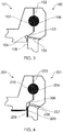
Figure 4 , anaerofoil 201 is configured to be joined to aplatform 202 by bi-casting. Theplatform 202 is an example of a second component to which the aerofoil is configured to be bi-cast. The aerofoil includes afirst face 203 including abi-cast groove 204 for joining the aerofoil to the second component by bi-casting. That is, theplatform 202 includes a correspondingbi-cast groove 210, which faces thebi-cast groove 204 of the aerofoil when the aerofoil is inserted into the platform. Then, liquid metal may be poured into the space, thus joining and securing the aerofoil to the platform. - The
aerofoil 201 further comprises asecond face 205 which joins, or is part of the external, or gas washed surface of the aerofoil. In other words, thesecond face 205 is connected to the external main body of the aerofoil. That is, this face continues along the span of the aerofoil, and is the face over which the main air flow of the engine passes. - The
second face 205 may be coated with athermal barrier coating 209, which insulates the body of theaerofoil 201 from the gas path air, which is at a high temperature. The thermal barrier coating may be any suitable coating known in the art, such as yttria-stabilized zirconia. The thermal barrier coating may comprise two layers, the layers being a bond layer and a top layer. The bond later may be platinum, aluminium, platinum aluminide, or a CoNiCrAlY, and the top layer may be yttria-stabilized zirconia. Any other suitable coating and combination of layers may also be used. - The
aerofoil 201 further comprises anangled sealing face 206 located between the first and second face. In other words, the angled sealingface 206 joins thefirst face 203 to thesecond face 205. Theangled sealing face 206 is angled with respect to thesecond face 205. The angle may be an obtuse angle, as shown inFigure 4 , or may be a right angle, as shown inFigure 5 . Theangled sealing face 206 serves to provide a sealing interface between thefirst face 203 and thesecond face 205. This may prevent leakage of bi-cast material during the bi-casting process, and prevent gas path air from coming into contact with the bi-cast metal. It may also maintain the aerofoil at the correct radial position. - The
aerofoil 201 further comprises aconcave face 207 forming a recessed surface at the intersection of the sealing face and the second face. That is, between theangled sealing face 206 and thesecond face 205, a concave recess is formed. The concave face forming a recessed surface may be referred to generally as a "recess". It will be understood that these two terms are interchangeable. - The
concave face 207 can be thought of as at the location at which the join or "corner" between thesecond face 205 and the angled sealingface 208 would have been if the recess were not otherwise present. The recess may be integrally formed. Alternatively, the aerofoil may be formed initially with a corner between thesecond face 205 and the angled sealingface 206. Subsequently, the removal of material at this location then forms the recess. - The
concave face 207 forming a recess can be formed, for example, by milling, to remove the material at the corner or intersection between thesecond face 205 and the angled sealingface 206. Because the material to be removed is on the outside of the aerofoil, a variety of machining processes can be used to remove the material and thus form the recess. Suitable methods of machining are, for example, grinding, milling, electrochemical machining (ECM), electrical discharge machining (EDM). It will be noted that this list is non-exhaustive and other methods of machining may be suitable. These processes allow easier and cheaper manufacture compared to the prior art, in which complicated milling of the platform in order to form an undercut must be undertaken. - The cross-sectional shape of the
concave face 207 may be a continuous curve between the sealingface 208 and thesecond face 205, as shown inFigure 4 . This may have the advantage of avoiding stress concentrations. The continuous curve may be of any suitable shape, and may be determined by the shape of the tool used to form the recess. -
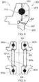
Figure 4 shows an arrangement in which the recess forms a smooth continuous curve between thesecond face 205 and the angled sealingface 206. However, the concave face may also take other shapes, such as the one shown inFigure 5 , which has two straight sides with a right angle therebetween. This forms an L shape. - It will also be understood that "concave" does not necessarily mean that the surface has a smooth or continuous curve. The term "concave" can also refer to a shape which curves inwards, but also has corners or discontinuities, such as in, for example, a "concave polygon". Thus, the recessed surface may have a discontinuity or corner. In other words, there may be a step change in the gradient of the surface, causing a sudden change of direction.
- As set out above, the cross-sectional shape of the
concave face 207 may be an L shape between thesecond face 205 and the angled sealingface 206.. That is, a right angle is formed in the face. This may allow the radial position of the face to be more easily measured and thus better controlled. Alternatively, theconcave face 207 may have a different shape which includes a corner, with the angle of a corner being a different angle to a right angle. Rather, the angle could be any angle which results in a generally concave shape. It will be appreciated that the shape of the recess may be determined by the method chosen to form the recess. - It will also be noted that, in
Figure 5 , the angled sealingface 206 is at a right angle to thesecond face 205, and at a right angle to thefirst face 203. However, arrangements are possible in which theconcave face 207 has a discontinuity (for example, is an L-shape) and the angled sealing face is at an obtuse angle to thesecond face 205, as shown inFigure 4 . Likewise, the reverse arrangement, in which the angled sealingface 206 is at a right angle to thesecond face 205, and theconcave face 207, and thus the recess surface, has a cross-section which is a continuous curve, as shown inFigure 4 . - It will be noted that
Figure 5 does not show a thermal barrier coating. It will however be appreciated that a thermal barrier coating similar to that shown inFigure 4 could be provided in the arrangement ofFigure 5 . - The aerofoil may further comprise a
purge flow hole 208, which may take the form of a through hole. One end of the through hole may be in theconcave face 207, and the other end may be at the interior of the aerofoil such that it connects with a cooling air flow path within the aerofoil. Thus, cooling air flows from the cooling air flow path into the recess, which purges gas path air from the space formed between the recess and the platform. If this purge air were not provided, gas path air may otherwise fill the space, and overheat the aerofoil and platform, which could in turn cause oxidation and reduce the life of the components. - A purge flow hole may also be provided in the platform, passing from the outside of the platform to the space between the aerofoil recess and the platform. Purge flow holes may also be provided in both the aerofoil and the platform.
-
Figure 6 shows an aerofoil 301 according to the present disclosure mounted in two platforms 302 and 303. This may be, for example, a stator vane mounted between two endwalls in a vane ring.Figure 6 thus shows a section through the aerofoil in context. It will be understood thatFigure 6 shows a single aerofoil 301 with twowalls Wall 301a is mounted at one end in afirst part 302a of platform 302, and at the other end in afirst part 303a of platform 303. Wall 301 is mounted at one end in asecond part 302b of platform 302, and at the other end in asecond part 303b of platform 303. - The middle of the aerofoil 301 may be hollow, and cooling air may pass into the middle of the blade through
inlet passages purge air holes 305 in order to purge the gap between the platform and the aerofoil. - As set out above, the recess is machined into the aerofoil between the second face and the angled sealing face. This means that complicated machining of the platform is not required to provide an undercut. It also provides a location face so that the purge air holes can be drilled accurately. Further still, when a thermal barrier coating is sprayed onto the second face, the thermal barrier coating can be allowed to overspray into the recess, which ensures that the coating does not fade out before the boundary of the gas path surface, and also means that the purge flow holes are not blocked by the coating.
- When the purge flow holes are provided in the aerofoil, the
concave face 207 forming a recessed surface means that the correct location for drilling of the purge flow holes can be located easily by virtue of it being in the recess. In contrast, in arrangements in which the recess is formed in the platform, the purge flow hole must be drilled very close to the intersection, or corner between the angled sealing face and the second face so that it lines up with the undercut recess in the platform, but care must be taken not to drill through the angled sealing face, which would adversely affect the purge flow. Thus, providing the recess on the aerofoil allows for simple and accurate location of thepurge flow hole 208. - When a thermal barrier coating is applied to the gas path surfaces of the components, this is typically done by spraying the coating on to the surfaces. At the edge of the gas path surfaces, where spraying is stopped, it is difficult to stop the spraying at exactly the correct location and maintain the optimum thickness of the coating. The coating may either fade out before the edge of the surface where the spraying has been stopped, or may overspray onto another surface. Both fading out of the coating (i.e. underspray) and overspray can have undesirable effects. Fade out means that the thermal barrier coating is not as effective in the locations where the fading occurs, and overspray may result in poor sealing if it is oversprayed onto a sealing surface, or may block the purge spray holes if it is oversprayed onto the location of a purge flow hole.
- As shown in
Figure 4 , the recess of the present disclosure allows the thickness of thecoating 209 to be maintained to the end of the gas washed surface, because a small amount of overspray into the aerofoil recess does not adversely affect the sealing or the purge flow holes. Thus, the effectiveness of the thermal barrier coating can be improved, whilst reducing the risk of the thermal barrier coating adversely affecting other parts of the assembly. - It will be understood that the invention is not limited to the embodiments above described and that various modifications and improvements can be made without departing from the concepts described herein. Except where mutually exclusive, any of the features may be employed separately or in combination with any other features, and the disclosure extends to and includes all combinations and sub-combinations of one or more features described herein.
Claims (14)
- An aerofoil (201) configured to be connected to a second component (202), the aerofoil comprising:a first face (203) including a bi-cast groove (204) for joining the aerofoil to the second component by bi-casting;a second face (205) connected to a gas path surface of the aerofoil;an angled sealing face (206) between the first and second face, the angled sealing face being angled with respect to the second face and configured to provide a sealing interface between the first face and the second face; anda concave face (207) forming a recessed surface at the intersection of the sealing face and the second face.
- The aerofoil (201) according to claim 1, further comprising a through-hole (208), wherein one end of the through-hole opens at the concave face (207).
- The aerofoil (201) according to claim 1 or 2, wherein the second face (205) is coated with a thermal barrier coating (209).
- The aerofoil (201) according to any preceding claim, wherein the angle between the angled sealing face (206) and the second face (205) is an obtuse angle.
- The aerofoil (201) according to any one of claims 1-3, wherein the angle between the angled sealing face (206) and the second face (205) is a right angle.
- The aerofoil (201) according to any preceding claim, wherein the first face (203) is at the root of the aerofoil.
- The aerofoil (201) according to any one of claims 1-6, wherein the first face (203) is at the tip of the aerofoil.
- The aerofoil (201) according to any preceding claim, wherein the aerofoil is a stator vane.
- The aerofoil (201) according to any one of claims 1-7, wherein the aerofoil is a rotor blade.
- The aerofoil (201) according to any preceding claim, wherein the cross-section of the recessed surface is a continuous curve between the angled sealing face (206) and the second face (205).
- The aerofoil (201) according to any one of claims 1-10, wherein the cross-section of the recessed surface includes a discontinuity.
- An assembly comprising the aerofoil (201) according to any preceding claim, and the second component (202), wherein the aerofoil and second component are joined by bi-cast metal filling the bi-cast groove of the aerofoil (204) and a corresponding bi-cast groove (210) on the second component.
- A method of manufacturing an aerofoil comprising:providing an aerofoil (201) with a first face (203) including a bi-cast groove (204); a second face (205) connected to a main body of the aerofoil; and an angled sealing face (206) between the first and second face, the angled sealing face being angled with respect to the second face and configured to seal the bi-cast groove; andremoving material at the intersection of the angled sealing face and the second face to form a concave face (207), thus forming a recessed surface.
- A method of manufacturing an assembly comprising:manufacturing an aerofoil (201) according to the method of claim 13; andjoining the aerofoil to a second component (202) by filling the bi-cast groove (204) of the aerofoil and a corresponding bi-cast groove (210) on the second component with bi-cast metal.
Applications Claiming Priority (1)
| Application Number | Priority Date | Filing Date | Title |
|---|---|---|---|
| GBGB1720314.2A GB201720314D0 (en) | 2017-12-06 | 2017-12-06 | Aerofil joint recess |
Publications (1)
| Publication Number | Publication Date |
|---|---|
| EP3495622A1 true EP3495622A1 (en) | 2019-06-12 |
Family
ID=60950424
Family Applications (1)
| Application Number | Title | Priority Date | Filing Date |
|---|---|---|---|
| EP18207140.7A Withdrawn EP3495622A1 (en) | 2017-12-06 | 2018-11-20 | Aerofoil, corresponding assembly and methods of manufacturing |
Country Status (4)
| Country | Link |
|---|---|
| US (1) | US20190168295A1 (en) |
| EP (1) | EP3495622A1 (en) |
| CN (1) | CN109882246A (en) |
| GB (1) | GB201720314D0 (en) |
Citations (4)
| Publication number | Priority date | Publication date | Assignee | Title |
|---|---|---|---|---|
| US20110033285A1 (en) * | 2008-12-29 | 2011-02-10 | Techspace Aero | Assembly for a stator stage of a turbomachine, the assembly comprising an outer shroud and at least one stationary vane |
| WO2016121163A1 (en) * | 2015-01-27 | 2016-08-04 | 三菱重工業株式会社 | Turbine blade, turbine, and method for manufacturing turbine blade |
| EP3103580A1 (en) * | 2015-06-12 | 2016-12-14 | General Electric Technology GmbH | Method for manufacturing a blading member assembly, and blading member assembly |
| EP3147452A1 (en) * | 2015-09-22 | 2017-03-29 | General Electric Technology GmbH | Turboengine blading member |
-
2017
- 2017-12-06 GB GBGB1720314.2A patent/GB201720314D0/en not_active Ceased
-
2018
- 2018-11-20 US US16/196,330 patent/US20190168295A1/en not_active Abandoned
- 2018-11-20 EP EP18207140.7A patent/EP3495622A1/en not_active Withdrawn
- 2018-12-06 CN CN201811487203.2A patent/CN109882246A/en active Pending
Patent Citations (4)
| Publication number | Priority date | Publication date | Assignee | Title |
|---|---|---|---|---|
| US20110033285A1 (en) * | 2008-12-29 | 2011-02-10 | Techspace Aero | Assembly for a stator stage of a turbomachine, the assembly comprising an outer shroud and at least one stationary vane |
| WO2016121163A1 (en) * | 2015-01-27 | 2016-08-04 | 三菱重工業株式会社 | Turbine blade, turbine, and method for manufacturing turbine blade |
| EP3103580A1 (en) * | 2015-06-12 | 2016-12-14 | General Electric Technology GmbH | Method for manufacturing a blading member assembly, and blading member assembly |
| EP3147452A1 (en) * | 2015-09-22 | 2017-03-29 | General Electric Technology GmbH | Turboengine blading member |
Also Published As
| Publication number | Publication date |
|---|---|
| US20190168295A1 (en) | 2019-06-06 |
| GB201720314D0 (en) | 2018-01-17 |
| CN109882246A (en) | 2019-06-14 |
Similar Documents
| Publication | Publication Date | Title |
|---|---|---|
| EP3543468B1 (en) | Turbine tip shroud assembly with plural shroud segments having inter-segment seal arrangement | |
| US9021816B2 (en) | Gas turbine engine turbine vane platform core | |
| EP3121382B1 (en) | Gas turbine engines including channel-cooled hooks for retaining a part relative to an engine casing structure | |
| US9074484B2 (en) | Cooled rotor blade | |
| US10975705B2 (en) | Gas turbine engine airfoil with wishbone baffle cooling scheme | |
| US9080452B2 (en) | Gas turbine engine airfoil with vane platform cooling passage | |
| US10415403B2 (en) | Cooled blisk for gas turbine engine | |
| US10920601B2 (en) | Blade outer air seal fin cooling assembly and method | |
| EP3043026B1 (en) | High lift airfoil and corresponding method of vectoring cooling air | |
| EP4028643B1 (en) | Turbine blade, method of manufacturing a turbine blade and method of refurbishing a turbine blade | |
| US10738629B2 (en) | Gas turbine guide vane segment and method of manufacturing | |
| US10344620B2 (en) | Air cooled component for a gas turbine engine | |
| US20170335692A1 (en) | Refractory metal core and components formed thereby | |
| EP3498971B1 (en) | Aerofoil for a gas turbine engine comprising a dividing sheet | |
| EP3495622A1 (en) | Aerofoil, corresponding assembly and methods of manufacturing | |
| JP2025051626A (en) | Title: TURBOMACHINE COMPONENT HAVING HOODED FILM COOLING HOLES EXPANDING FROM AN EXTERNAL WALL SURFACE | |
| EP3068580A1 (en) | Fluidic machining method and system | |
| US12497896B2 (en) | Airfoil assembly with platform film holes | |
| US11634990B2 (en) | Component with mechanical locking features incorporating adaptive cooling and method of making | |
| EP4553284A1 (en) | Turbine engine with a blade assembly having cooling holes |
Legal Events
| Date | Code | Title | Description |
|---|---|---|---|
| PUAI | Public reference made under article 153(3) epc to a published international application that has entered the european phase |
Free format text: ORIGINAL CODE: 0009012 |
|
| STAA | Information on the status of an ep patent application or granted ep patent |
Free format text: STATUS: THE APPLICATION HAS BEEN PUBLISHED |
|
| AK | Designated contracting states |
Kind code of ref document: A1 Designated state(s): AL AT BE BG CH CY CZ DE DK EE ES FI FR GB GR HR HU IE IS IT LI LT LU LV MC MK MT NL NO PL PT RO RS SE SI SK SM TR |
|
| AX | Request for extension of the european patent |
Extension state: BA ME |
|
| STAA | Information on the status of an ep patent application or granted ep patent |
Free format text: STATUS: REQUEST FOR EXAMINATION WAS MADE |
|
| 17P | Request for examination filed |
Effective date: 20191210 |
|
| RBV | Designated contracting states (corrected) |
Designated state(s): AL AT BE BG CH CY CZ DE DK EE ES FI FR GB GR HR HU IE IS IT LI LT LU LV MC MK MT NL NO PL PT RO RS SE SI SK SM TR |
|
| RAP1 | Party data changed (applicant data changed or rights of an application transferred) |
Owner name: ROLLS-ROYCE PLC |
|
| GRAP | Despatch of communication of intention to grant a patent |
Free format text: ORIGINAL CODE: EPIDOSNIGR1 |
|
| STAA | Information on the status of an ep patent application or granted ep patent |
Free format text: STATUS: GRANT OF PATENT IS INTENDED |
|
| RIC1 | Information provided on ipc code assigned before grant |
Ipc: B22D 25/02 20060101ALI20200317BHEP Ipc: F01D 5/18 20060101ALI20200317BHEP Ipc: F01D 5/28 20060101ALI20200317BHEP Ipc: F01D 9/04 20060101AFI20200317BHEP Ipc: F01D 9/06 20060101ALI20200317BHEP Ipc: B22D 19/04 20060101ALI20200317BHEP |
|
| INTG | Intention to grant announced |
Effective date: 20200331 |
|
| STAA | Information on the status of an ep patent application or granted ep patent |
Free format text: STATUS: THE APPLICATION IS DEEMED TO BE WITHDRAWN |
|
| 18D | Application deemed to be withdrawn |
Effective date: 20200811 |