EP3495611A1 - Apparatus for controlled delivery of cooling air to turbine blades in a gas turbine - Google Patents
Apparatus for controlled delivery of cooling air to turbine blades in a gas turbine Download PDFInfo
- Publication number
- EP3495611A1 EP3495611A1 EP17205756.4A EP17205756A EP3495611A1 EP 3495611 A1 EP3495611 A1 EP 3495611A1 EP 17205756 A EP17205756 A EP 17205756A EP 3495611 A1 EP3495611 A1 EP 3495611A1
- Authority
- EP
- European Patent Office
- Prior art keywords
- rotor
- row
- heat shield
- cooling air
- shield elements
- Prior art date
- Legal status (The legal status is an assumption and is not a legal conclusion. Google has not performed a legal analysis and makes no representation as to the accuracy of the status listed.)
- Granted
Links
Images


Classifications
-
- F—MECHANICAL ENGINEERING; LIGHTING; HEATING; WEAPONS; BLASTING
- F01—MACHINES OR ENGINES IN GENERAL; ENGINE PLANTS IN GENERAL; STEAM ENGINES
- F01D—NON-POSITIVE DISPLACEMENT MACHINES OR ENGINES, e.g. STEAM TURBINES
- F01D11/00—Preventing or minimising internal leakage of working-fluid, e.g. between stages
- F01D11/001—Preventing or minimising internal leakage of working-fluid, e.g. between stages for sealing space between stator blade and rotor
-
- F—MECHANICAL ENGINEERING; LIGHTING; HEATING; WEAPONS; BLASTING
- F01—MACHINES OR ENGINES IN GENERAL; ENGINE PLANTS IN GENERAL; STEAM ENGINES
- F01D—NON-POSITIVE DISPLACEMENT MACHINES OR ENGINES, e.g. STEAM TURBINES
- F01D5/00—Blades; Blade-carrying members; Heating, heat-insulating, cooling or antivibration means on the blades or the members
- F01D5/02—Blade-carrying members, e.g. rotors
- F01D5/08—Heating, heat-insulating or cooling means
- F01D5/081—Cooling fluid being directed on the side of the rotor disc or at the roots of the blades
-
- F—MECHANICAL ENGINEERING; LIGHTING; HEATING; WEAPONS; BLASTING
- F01—MACHINES OR ENGINES IN GENERAL; ENGINE PLANTS IN GENERAL; STEAM ENGINES
- F01D—NON-POSITIVE DISPLACEMENT MACHINES OR ENGINES, e.g. STEAM TURBINES
- F01D5/00—Blades; Blade-carrying members; Heating, heat-insulating, cooling or antivibration means on the blades or the members
- F01D5/30—Fixing blades to rotors; Blade roots ; Blade spacers
- F01D5/3007—Fixing blades to rotors; Blade roots ; Blade spacers of axial insertion type
- F01D5/3015—Fixing blades to rotors; Blade roots ; Blade spacers of axial insertion type with side plates
Definitions
- the present invention relates to an apparatus for controlled delivery of cooling air to turbine blades in a turbine section of a gas turbine power plant.
- the present invention relates to an apparatus for controlling cooling air delivery to rotor heat shield cavities to protect the rotor material against hot gas.
- a gas turbine for power plants comprises an upstream compressor, a combustor assembly and a downstream turbine.
- the turbine includes a rotor comprising a compressor section and a turbine section.
- downstream and upstream refer to the direction of the main gas flow passing through the gas turbine.
- the compressor comprises an inlet supplied with air and a plurality of blades compressing the passing air.
- the major part of the compressed air flows into a combustor where the compressed air is mixed with at least one fuel. This mixture is combusted in the combustor leading to a significant temperature rise.
- the resulting hot gas leaves the combustor and is expanded in the turbine, producing mechanical work on the rotor.
- Devices called rotor heat shields (RHS) are generally inserted between two adjacent blade rows to form cavities that can be supplied with cooling air.
- the hot gas pressure decreases from one blade row to the following. It is known in the art that the pressure of the cooling air supplied to the individual blades rows at the root of the blades should be above the hot gas pressure at that blade row to avoid leakage of hot gas into cooling cavities; however, the cooling air pressure should not be too high in order to avoid excessive flow of cooling air into the hot gas path, which would reduce efficiency.
- Controlling cooling air delivery is even more complex when air is supplied to two blade rows from a single source.
- An object of the present invention is to provide an apparatus for controlled delivery of cooling air to turbine blades in a gas turbine which addresses the above problems.
- the apparatus includes:
- pressure drop along the different portions of the rotor heat shield passage can be controlled so as to ensure optimum local balance with the pressure of the hot gas.
- two portions or cavities of the rotor heat shield passage communicate through the aperture in the radial portion of the rotor heat shield elements, which allows to control pressure in the two portions even though only one of them is supplied with cooling air.
- the rotor shield elements include at least one feature configured to cooperate with an axial finger extending from the platform portion of the blades of at least one row in order to lock said rotor shield elements circumferentially; the opening is facing the features of the rotor shield elements, so that it can be used to receive the finger of a respective blade.
- lock plates are provided with hooks for coupling with said rotor unit; this makes assembly easy and quick.
- the apparatus includes at least one, and preferable all, of:
- the invention relates to a gas turbine including:
- a gas turbine 1 (only partially shown) includes a rotor 2 rotatable about a rotor axis (not shown) and a stator 3.
- rotor 2 includes a rotor unit 4 and a plurality of turbine blades 5 secured to the rotor unit 4 and disposed in a plurality of circumferential blade rows 6, 7, 8.
- Stator 3 is provided with a plurality of turbine vanes 9 disposed in a plurality of circumferential vane rows 10, 11, 12 that precede the respective blade rows 5, 6, 7 in the axial direction of the hot gas flow, indicated by arrow H.
- Three vane rows are shown in figure 1 , but the number of vane rows is typically larger than three.
- the inner tip of the vane 9 is integrally connected to an inner vane platform 14 that extends circumferentially until the adjacent vane platforms; the gaps between two adjacent vane platforms 14 is sealed with a seal.
- Blades 5 have, each, a firtree shaped shank portion 15 that is inserted in a firtree seat 16 of rotor unit 4 ( fig. 6 ), a platform portion 17 and an airfoil 18.
- Blade rows 6, 7, 8 are axially spaced with respect to one another, and rotor unit 4 has annular recesses 19, 20 in between each pair of rows (5,6; 6,7).
- Turbine 1 also includes a plurality of rotor heat shield elements 23 (hereinafter, for brevity sake, RHS elements) disposed in circumferential RHS rows 24, 25. Two rows only of RHS elements are shown, but the number of rows is obviously dependent on the number of blade rows and typically greater than two.
- RHS elements rotor heat shield elements
- Each RHS element 23 ( figures 1-3 ) comprises a mushroom shaped root portion 26 engaged in an undercut mushroom shaped annular seat 27 at the bottom of the respective annular recess 19 or 20, an intermediate radial portion 28 and a circumferential shroud band 29.
- the shroud bands 29 of the RHS elements 23 in each row are joined to one another by axial seals (not shown) to form a substantially continuous annual band, that is sealed circumferentially to each of the adjacent blade rows by means of circumferential seals 30.
- Root portions 26 are sealed against the bottom of annular seat 27 by a circumferential wire seal 39.
- Shroud bands 29 have preferably a plurality of inclined sealing fins 31, which are alternatingly lower and higher and projecting outwardly to cooperate at a short radial distance with a stepped inner sealing contour 32 of inner ring 14 of the stator. This reduces unwanted hot gas leakage between rotor 2 and stator 3.
- the RHS elements 23 of rows 24, 25 delimit, with the adjacent blade rows 6,7 and 7,8 respectively, a plurality of rotor heat shield (RHS) cavities 33, 34, 35, 36 that communicate with one another to define a path for cooling air.
- cooling air is fed to RHS cavity 33 via a passage 37 in rotor unit 4 which opens into a passage 38 through blade row 6 ( fig. 2 ).
- Blades 5 are axially blocked by lock plates 40, 41, 42, 43, which are disposed side-by-side in circumferential rows.
- Lock plates 40-43 have a radially inner edge 44 engaging a corresponding seat 45 on rotor unit 4 and a radially outer edge 46 engaging a corresponding seat 47 in the respective blade 5 ( fig. 2 ).
- radial portions 28 of RHS elements 23 and/or lock plates 40-43 may include apertures 48, 49 to allow a controlled air flow therethrough and thereby define a predetermined pressure drop between adjacent cavities 33, 34 and 35, 36.
- the pressure within each of the cavities can be controlled so as to be greater than the pressure of hot gases at the corresponding axial portion of the hot gas path, so as to avoid leakage of hot gas into the RHS cavities, but not too high so as to avoid excessive leakage of cooling air into the hot gas path.
- pressure in each section of the RHS path is maintained in the range of 100-150% of the corresponding hot gas pressure.
- apertures 48 in radial portion 28 of RHS elements 23 connect cavity 33 to cavity 34 and cavity 35 to cavity 36.
- Apertures 49 in lock plates 41 control air flow between cavity 34 and passages 38 through blade row 7.
- RHS elements 23 are locked in a circumferential direction by axial fingers 50 extending from blades 5 and engaging corresponding features 60 of RHS elements 23, as known per se e.g. from US 2008/0181778-A .
- Such features may include a seat of any kind, e.g. a space between two projections of RHS elements 23.
- lock plates 42 have the shape of an annulus sector and are placed side by side in a circumferential row.
- inner edges 44 are sealed with respect to seat 45 by means of a wire seal 61 that is housed within a groove 62 in lock plates 52 and cooperates axially with one side of seat 45 (see enlarged detail in fig. 4 ).
- Lock plates 42 are provided with a preferably rectangular aperture 49 which, in addition to controlling the flow of cooling air as described previously, has the function of allowing a corresponding finger 50 to pass through ( fig. 3 , 4 ) .
- Lock plates 42 have hooks 51 configured to couple lock plates 42 to rotor unit 4.
- two hooks 51 are arranged at opposite radial edges of the lock plate 42 in the proximity of the outer edge and engage with lugs 52 of the rotor unit located at opposite sides of each firtree seat 16.
- Lock plates 41 ( figures 4 and 6 ) have preferably a substantially trapezoidal shape with a longer base connected to rotor unit 4 and a shorter base connected to a respective blade 5.
- Lock plates 41 have a central cut-out opening 52 delimiting a flexible tab 53 which is bent axially towards the respective blade 5 so as to exert an elastic force thereon and recover axial play.
- Lock plates 41 also have an opening 54 close to rotor unit 4 so as to allow cooling air flow at the blade roots.
- Blades 5 of row 6 have platform portions 17 extending radially outwardly of the shroud bands 29 of RHS elements 23 of RHS row 24.
- Platform portions 17 include shiplap seal features 55 ( fig. 8 ) configured to cooperate with corresponding features of an adjacent blade so as to avoid gas leakage therebetween.
- cooling air is fed through passage 37 into passage 38; part of this flow is used to cool blades 5 of row 6 internally, as known per se.
- cooling air is fed from passage 38 into cavity 33, and hence to cavity 34 through apertures 48 in radial portions 28 of RHS elements 23. Cooling air than flows from cavity 34 through apertures 49 in lock plates into passages 38 through blade row 7; part of the flow cools blades 5 of row 7 internally, as known per se.
- the cross section of apertures 48 and 49 is calibrated to obtain a desired pressure drop at each transition, so as to match the pressure in cavities 33, 34, 35, 36 with the pressure of surrounding hot gas and, preferably, be in the range of 100-150% of the pressure of surrounding hot gas.
Landscapes
- Engineering & Computer Science (AREA)
- Mechanical Engineering (AREA)
- General Engineering & Computer Science (AREA)
- Turbine Rotor Nozzle Sealing (AREA)
Abstract
Description
- The present invention relates to an apparatus for controlled delivery of cooling air to turbine blades in a turbine section of a gas turbine power plant. In particular, the present invention relates to an apparatus for controlling cooling air delivery to rotor heat shield cavities to protect the rotor material against hot gas.
- As is known, a gas turbine for power plants (in the following, "gas turbine" only) comprises an upstream compressor, a combustor assembly and a downstream turbine. The turbine includes a rotor comprising a compressor section and a turbine section.
- The terms downstream and upstream as used herein refer to the direction of the main gas flow passing through the gas turbine.
- In particular, the compressor comprises an inlet supplied with air and a plurality of blades compressing the passing air. The major part of the compressed air flows into a combustor where the compressed air is mixed with at least one fuel. This mixture is combusted in the combustor leading to a significant temperature rise. The resulting hot gas leaves the combustor and is expanded in the turbine, producing mechanical work on the rotor.
- While the turbine blades are made of a material designed to withstand the hot gas temperatures, and thus costly, the rotor is generally made of a less costly material with a lower resistance to high temperatures. Therefore, a flow of cooling air must be provided in the rotor section, below the hot gas path, to protect the rotor material against the hot gas temperature. Devices called rotor heat shields (RHS) are generally inserted between two adjacent blade rows to form cavities that can be supplied with cooling air.
- In the turbine section, the hot gas pressure decreases from one blade row to the following. It is known in the art that the pressure of the cooling air supplied to the individual blades rows at the root of the blades should be above the hot gas pressure at that blade row to avoid leakage of hot gas into cooling cavities; however, the cooling air pressure should not be too high in order to avoid excessive flow of cooling air into the hot gas path, which would reduce efficiency.
- Controlling cooling air delivery is even more complex when air is supplied to two blade rows from a single source.
- An object of the present invention is to provide an apparatus for controlled delivery of cooling air to turbine blades in a gas turbine which addresses the above problems.
- According to a first aspect of the present invention, the apparatus includes:
- a plurality of rotor heat shield elements disposed in a circumferential row between a first and a second row of turbine blades, each shield element having a root portion contoured so as to fit in a seat of the rotor unit, an intermediate radial portion and a shroud band configured to be axially interposed between platform portions of the turbine blades of the first and second turbine blade row, the rotor heat shield elements configured to define with a rotor unit of the turbine a rotor heat shield passage that is fed with cooling air; and
- at least a row of lock plates configured to secure axially at least one of said first and second rows of turbine blades to said rotor unit, said lock plates facing said rotor heat shield elements,
- According to the invention, pressure drop along the different portions of the rotor heat shield passage can be controlled so as to ensure optimum local balance with the pressure of the hot gas.
- According to an embodiment, two portions or cavities of the rotor heat shield passage communicate through the aperture in the radial portion of the rotor heat shield elements, which allows to control pressure in the two portions even though only one of them is supplied with cooling air.
- In an embodiment, the rotor shield elements include at least one feature configured to cooperate with an axial finger extending from the platform portion of the blades of at least one row in order to lock said rotor shield elements circumferentially; the opening is facing the features of the rotor shield elements, so that it can be used to receive the finger of a respective blade.
- Advantageously, lock plates are provided with hooks for coupling with said rotor unit; this makes assembly easy and quick.
- According to a preferred embodiment, the apparatus includes at least one, and preferable all, of:
- a circumferential wire seal between the root portions of the said rotor heat shield elements and said rotor unit,
- a circumferential wire seal between said lock plates and said rotor unit,
- circumferential seals between the shroud bands the said blades, and
- axial seals between each pair of adjacent shroud bands.
- This allows to reduce, and preferably eliminate, any undesired leaking paths for the cooling air.
- According to another aspect, the invention relates to a gas turbine including:
- a rotor unit;
- at least a first plurality of turbine blades disposed in a first circumferential row around the rotor unit and secured thereto,
- at least a second plurality of turbine blades disposed in a second circumferential row around the rotor unit and secured thereto,
- the first row and the second row being axially spaced with respect to one another,
- a plurality of rotor heat shield elements disposed in a circumferential row between said first and second rows of turbine blades, each shield element having a root portion contoured so as to fit in a seat of the rotor unit, an intermediate radial portion and a shroud band configured to be axially interposed between the first and second row of turbine blades, the rotor heat shield elements defining with said rotor unit a rotor heat shield passage that is fed with cooling air,
- at least a row of lock plates configured to secure at least one of sais first and second rows of turbine blades to said rotor unit, said lock plates facing said rotor heat shield elements,
- For a better comprehension of the present invention, a preferred embodiment thereof will be described hereafter, by way of a non-limiting example and referring to the attached drawings, where:
-
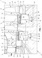
Figure 1 is a partial axial cross section of an apparatus for controlled delivery of cooling air to turbine blades according to the present invention; -
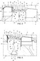
Figure 2 is an enlarged view of a portion offigure 1 ; -
Figure 3 is a detailed view of another portion offigure 1 ; -
Figure 4 is a side view, partly sectioned, of a turbine blade of a gas turbine including the apparatus; -
figure 5 is an axial view from one side of a detail offigure 4 ; -
Figure 6 is ax axial view from an opposite side of a detail offigure 4 ; -
Figure 7 is a perspective view of a component of the apparatus of the invention; and -
Figure 8 is partial cross-section taken along line VIII-VIII infigure 1 . - Referring now to
figure 1 , a gas turbine 1 (only partially shown) includes arotor 2 rotatable about a rotor axis (not shown) and astator 3. - As is well known in the art,
rotor 2 includes arotor unit 4 and a plurality ofturbine blades 5 secured to therotor unit 4 and disposed in a plurality ofcircumferential blade rows figure 1 , but the number of blade rows is typically larger than three.Stator 3 is provided with a plurality ofturbine vanes 9 disposed in a plurality ofcircumferential vane rows respective blade rows figure 1 , but the number of vane rows is typically larger than three. The inner tip of thevane 9 is integrally connected to aninner vane platform 14 that extends circumferentially until the adjacent vane platforms; the gaps between twoadjacent vane platforms 14 is sealed with a seal. -
Blades 5 have, each, a firtree shapedshank portion 15 that is inserted in afirtree seat 16 of rotor unit 4 (fig. 6 ), aplatform portion 17 and anairfoil 18. -
Blade rows rotor unit 4 hasannular recesses - Turbine 1 also includes a plurality of rotor heat shield elements 23 (hereinafter, for brevity sake, RHS elements) disposed in
circumferential RHS rows - Each RHS element 23 (
figures 1-3 ) comprises a mushroomshaped root portion 26 engaged in an undercut mushroom shapedannular seat 27 at the bottom of the respectiveannular recess radial portion 28 and acircumferential shroud band 29. Theshroud bands 29 of theRHS elements 23 in each row are joined to one another by axial seals (not shown) to form a substantially continuous annual band, that is sealed circumferentially to each of the adjacent blade rows by means ofcircumferential seals 30.Root portions 26 are sealed against the bottom ofannular seat 27 by acircumferential wire seal 39. - A radial
small bore 56 in therotor unit 4, opening into the undercut portion of seat 27 (fig. 3 ), allows to insert a control wire (not shown) to check whether the circumferential position of RHS elements is correct, as shown e.g. inUS 2008/0181778-A . -
Shroud bands 29 have preferably a plurality of inclined sealingfins 31, which are alternatingly lower and higher and projecting outwardly to cooperate at a short radial distance with a steppedinner sealing contour 32 ofinner ring 14 of the stator. This reduces unwanted hot gas leakage betweenrotor 2 andstator 3. - As shown in
figures 2, 3 , theRHS elements 23 ofrows adjacent blade rows RHS cavity 33 via apassage 37 inrotor unit 4 which opens into apassage 38 through blade row 6 (fig. 2 ). -
Blades 5 are axially blocked bylock plates corresponding seat 45 onrotor unit 4 and a radiallyouter edge 46 engaging acorresponding seat 47 in the respective blade 5 (fig. 2 ). - As shown in
figure 2 and 3 ,radial portions 28 ofRHS elements 23 and/or lock plates 40-43 may includeapertures adjacent cavities apertures 48 inradial portion 28 ofRHS elements 23connect cavity 33 tocavity 34 andcavity 35 tocavity 36.Apertures 49 inlock plates 41 control air flow betweencavity 34 andpassages 38 throughblade row 7. -
RHS elements 23 are locked in a circumferential direction byaxial fingers 50 extending fromblades 5 and engagingcorresponding features 60 ofRHS elements 23, as known per se e.g. fromUS 2008/0181778-A . Such features may include a seat of any kind, e.g. a space between two projections ofRHS elements 23. - As shown in
figures 4 and 5 ,lock plates 42 have the shape of an annulus sector and are placed side by side in a circumferential row. Preferably, inner edges 44 are sealed with respect toseat 45 by means of awire seal 61 that is housed within agroove 62 inlock plates 52 and cooperates axially with one side of seat 45 (see enlarged detail infig. 4 ). -
Lock plates 42 are provided with a preferablyrectangular aperture 49 which, in addition to controlling the flow of cooling air as described previously, has the function of allowing acorresponding finger 50 to pass through (fig. 3 ,4 ) . -
Lock plates 42 havehooks 51 configured to couplelock plates 42 torotor unit 4. Preferably, twohooks 51 are arranged at opposite radial edges of thelock plate 42 in the proximity of the outer edge and engage withlugs 52 of the rotor unit located at opposite sides of eachfirtree seat 16. - Lock plates 41 (
figures 4 and6 ) have preferably a substantially trapezoidal shape with a longer base connected torotor unit 4 and a shorter base connected to arespective blade 5. -
Lock plates 41 have a central cut-outopening 52 delimiting aflexible tab 53 which is bent axially towards therespective blade 5 so as to exert an elastic force thereon and recover axial play. -
Lock plates 41 also have anopening 54 close torotor unit 4 so as to allow cooling air flow at the blade roots.Blades 5 ofrow 6 haveplatform portions 17 extending radially outwardly of theshroud bands 29 ofRHS elements 23 ofRHS row 24.Platform portions 17 include shiplap seal features 55 (fig. 8 ) configured to cooperate with corresponding features of an adjacent blade so as to avoid gas leakage therebetween. - In use, cooling air is fed through
passage 37 intopassage 38; part of this flow is used to coolblades 5 ofrow 6 internally, as known per se. - The remaining part of cooling air is fed from
passage 38 intocavity 33, and hence tocavity 34 throughapertures 48 inradial portions 28 ofRHS elements 23. Cooling air than flows fromcavity 34 throughapertures 49 in lock plates intopassages 38 throughblade row 7; part of the flow coolsblades 5 ofrow 7 internally, as known per se. - Finally, cooling air flows through
apertures 49 oflock plates 42 intocavity 35, and hence intocavity 36 throughapertures 48 ofRHS elements 23. - The cross section of
apertures cavities
Claims (15)
- An apparatus for controlled delivery of cooling air to turbine blades (5) in a gas turbine (1) including a rotor unit (4), at least a first plurality of turbine blades (5) disposed in a first circumferential row (6; 7) around the rotor unit (4) and secured thereto, at least a second plurality of turbine blades (5) disposed in a second circumferential row (7; 8) around the rotor unit (4) and secured thereto, the first row (6; 7) and the second row (7; 8) being axially spaced with respect to one another, the apparatus including:- a plurality of rotor heat shield elements (23) disposed in a circumferential row between said first and second rows of turbine blades (5), each heat shield element (23) having a root portion (26) contoured so as to fit in a seat (27) of the rotor unit (4), an intermediate radial portion (28) and a shroud band (29) configured to be axially interposed between the first and second rows (6, 7; 7, 8) of turbine blades (5), the rotor heat shield elements (23) configured to define with said rotor unit (4) a rotor heat shield passage (33, 34, 35, 36) that is fed with cooling air;- a plurality of lock plates (40, 41, 42, 43) disposed in a circumferential row and configured to secure axially at least one of said first and second rows (6, 7, 8) of turbine blades (5) to said rotor unit (4), said lock plates (41, 42, 43) facing said heat shield elements (23),characterized in that at least one of said radial portion (28) of the rotor shield elements (23) and the lock plates (41, 42, 43) include at least one opening (49; 54) for controlled flow of cooling air.
- An apparatus as claimed in claim 1, characterized by including a first cavity (33) between by the first row (6) of turbine blades (5) and the radial portion (28) of the shield elements (23) and a second cavity (34) between the radial portion (28) of the shield elements (23) and the second row (7) of turbine blades (5), one of said first and second cavity (33) being supplied by a source of cooling air, the other of said first and second cavity (34) being supplied with cooling air through an opening (48) in said radial portion (28) of the shield elements (23).
- An apparatus as claimed in claim 1, characterized in that said rotor shield elements (23) include at least one feature (60) configured to cooperate with an axial finger (50) extending from the blades (5) of at least one row (6, 7, 8) in order to lock said rotor shield elements (23) circumferentially.
- An apparatus as claimed in claim 3, characterized in that said lock plates (42) include an opening (49) facing said features of said rotor shield elements (23), said opening (49) being configured to receive said finger (50) of a respective blade (5).
- An apparatus as claimed in any of the preceding claims, characterized in that the lock plates (42) are provided with hooks (51) for coupling with said rotor unit (4) .
- An apparatus as claimed in any preceding claims, characterized by including a circumferential wire seal between the root portions (26) of the said rotor heat shield elements (23) and said rotor unit (4).
- An apparatus as claimed in any preceding claims, characterized by including a circumferential wire seal between said lock plates (41, 42) and said rotor unit (4).
- An apparatus as claimed in any preceding claims, characterized by including circumferential seals (30) between said shroud bands (29) and said blades (5), and axial seals between each pair of adjacent shroud bands (29).
- A gas turbine including:- a rotor unit (4);- at least a first plurality of turbine blades (5) disposed in a first circumferential row (6, 7) around the rotor unit (4) and secured thereto,- at least a second plurality of turbine blades (5) disposed in a second circumferential row (7, 8) around the rotor unit (4) and secured thereto,- the first row and the second row (6, 7; 7, 8) being axially spaced with respect to one another,- a plurality of rotor heat shield elements (23) disposed in a circumferential row between said first and second rows of turbine blades (5), each rotor shield element (23) having a root portion (26) contoured so as to fit in a seat (27) of the rotor unit (4), an intermediate radial portion (28) and a shroud band (29) configured to be axially interposed between the first and second row of turbine blades (5), the rotor heat shield elements (23) defining with said rotor unit (4) a rotor heat shield passage (33, 34, 35, 36) that is fed with cooling air,- at least a row of lock plates (40, 41, 42, 43) configured to secure at least one of sais first and second rows of turbine blades to said rotor unit (4), said lock plates facing said rotor heat shield elements (23),characterized in that said lock plates (42) include an opening (49) for controlled flow of cooling air between at least a first portion of said heat shield passage upstream of the lock plates (42) and a second portion of said heat shield passage downstream of the lock plates (42).
- A gas turbine as claimed in claim 9, characterized in that the blades (5) of at least one of said first and second rows (6, 7; 7, 8) have axial fingers (50), the rotor heath elements (23) having mating features (60) cooperating with said axial fingers (50) to lock said rotor shield elements (23) circumferentially, said axial fingers (50) of said blades (5) extending through said openings (49) of said locking plates (42).
- A gas turbine as claimed in claim 9 or 10, characterized in that said lock plates (42) include hooks (51) engaging corresponding seats in the rotor unit (4).
- A gas turbine as claimed in any of claims 9 to 11, characterized in that at least one of said first and second rows (6, 7; 7, 8) of blades (5) have platform portions (17) extending radially outwardly of said shroud bands (29) of the rotor heat shield elements (23).
- A gas turbine as claimed in claim 12, characterized in that said platform portions (17) include shiplap seal features configured to cooperate with corresponding features (55) of an adjacent blade (5).
- A gas turbine as claimed in any of claims 9 to 13, characterized in that the radial portions (28) of the rotor shield elements (23) include at least one opening (48) for controlled flow of cooling air.
- A gas turbine as claimed in any of claims 9 to 14, characterized in that shroud bands (29) have a plurality of inclined sealing fins (31) to cooperate at a short radial distance with a stepped inner sealing contour (32) of an inner ring (14) of the stator.
Priority Applications (2)
| Application Number | Priority Date | Filing Date | Title |
|---|---|---|---|
| EP17205756.4A EP3495611B1 (en) | 2017-12-06 | 2017-12-06 | Apparatus for controlled delivery of cooling air to turbine blades in a gas turbine |
| CN201811488034.4A CN110017175B (en) | 2017-12-06 | 2018-12-06 | Apparatus for controlled delivery of cooling air to turbine blades in a gas turbine |
Applications Claiming Priority (1)
| Application Number | Priority Date | Filing Date | Title |
|---|---|---|---|
| EP17205756.4A EP3495611B1 (en) | 2017-12-06 | 2017-12-06 | Apparatus for controlled delivery of cooling air to turbine blades in a gas turbine |
Publications (2)
| Publication Number | Publication Date |
|---|---|
| EP3495611A1 true EP3495611A1 (en) | 2019-06-12 |
| EP3495611B1 EP3495611B1 (en) | 2020-07-29 |
Family
ID=60627499
Family Applications (1)
| Application Number | Title | Priority Date | Filing Date |
|---|---|---|---|
| EP17205756.4A Active EP3495611B1 (en) | 2017-12-06 | 2017-12-06 | Apparatus for controlled delivery of cooling air to turbine blades in a gas turbine |
Country Status (2)
| Country | Link |
|---|---|
| EP (1) | EP3495611B1 (en) |
| CN (1) | CN110017175B (en) |
Cited By (1)
| Publication number | Priority date | Publication date | Assignee | Title |
|---|---|---|---|---|
| FR3120894A1 (en) * | 2021-03-19 | 2022-09-23 | Safran Aircraft Engines | TURBOMACHINE ROTOR, INCLUDING A LABYRINTH SEAL RING MOUNTED ON DISC FERRULES |
Citations (4)
| Publication number | Priority date | Publication date | Assignee | Title |
|---|---|---|---|---|
| GB988541A (en) * | 1962-03-06 | 1965-04-07 | Ruston & Hornsby Ltd | Gas turbine rotor cooling |
| US4884950A (en) * | 1988-09-06 | 1989-12-05 | United Technologies Corporation | Segmented interstage seal assembly |
| US20080181778A1 (en) | 2005-08-23 | 2008-07-31 | Alstom Technology Ltd | Locking and fixing device for a heat shield element for a rotor unit of a turbomachine |
| US20100074732A1 (en) * | 2008-09-25 | 2010-03-25 | John Joseph Marra | Gas Turbine Sealing Apparatus |
Family Cites Families (3)
| Publication number | Priority date | Publication date | Assignee | Title |
|---|---|---|---|---|
| FR2744761B1 (en) * | 1996-02-08 | 1998-03-13 | Snecma | LABYRINTH DISC WITH INCORPORATED STIFFENER FOR TURBOMACHINE ROTOR |
| DE102015111750A1 (en) * | 2015-07-20 | 2017-01-26 | Rolls-Royce Deutschland Ltd & Co Kg | Chilled turbine runner for an aircraft engine |
| DE102016208759A1 (en) * | 2016-05-20 | 2017-11-23 | Siemens Aktiengesellschaft | Rotor disc with front-side sealing element |
-
2017
- 2017-12-06 EP EP17205756.4A patent/EP3495611B1/en active Active
-
2018
- 2018-12-06 CN CN201811488034.4A patent/CN110017175B/en active Active
Patent Citations (4)
| Publication number | Priority date | Publication date | Assignee | Title |
|---|---|---|---|---|
| GB988541A (en) * | 1962-03-06 | 1965-04-07 | Ruston & Hornsby Ltd | Gas turbine rotor cooling |
| US4884950A (en) * | 1988-09-06 | 1989-12-05 | United Technologies Corporation | Segmented interstage seal assembly |
| US20080181778A1 (en) | 2005-08-23 | 2008-07-31 | Alstom Technology Ltd | Locking and fixing device for a heat shield element for a rotor unit of a turbomachine |
| US20100074732A1 (en) * | 2008-09-25 | 2010-03-25 | John Joseph Marra | Gas Turbine Sealing Apparatus |
Cited By (1)
| Publication number | Priority date | Publication date | Assignee | Title |
|---|---|---|---|---|
| FR3120894A1 (en) * | 2021-03-19 | 2022-09-23 | Safran Aircraft Engines | TURBOMACHINE ROTOR, INCLUDING A LABYRINTH SEAL RING MOUNTED ON DISC FERRULES |
Also Published As
| Publication number | Publication date |
|---|---|
| EP3495611B1 (en) | 2020-07-29 |
| CN110017175B (en) | 2023-08-04 |
| CN110017175A (en) | 2019-07-16 |
Similar Documents
| Publication | Publication Date | Title |
|---|---|---|
| US10480338B2 (en) | Bladed rotor arrangement including axial projection | |
| JP6739934B2 (en) | Gas turbine seals | |
| US8939711B2 (en) | Outer rim seal assembly in a turbine engine | |
| EP3184742B1 (en) | Turbine airfoil with trailing edge cooling circuit | |
| JP5986372B2 (en) | Cooling circuit for drum rotor | |
| EP2586974B1 (en) | Turbine bucket with platform leading edge scallop for performance and secondary flow, corresponding turbine wheel and method of controlling secondary purge air flow | |
| US10066488B2 (en) | Turbomachine blade with generally radial cooling conduit to wheel space | |
| EP3645839B1 (en) | Turbine assembly for impingement cooling and method of assembling | |
| EP3179032B1 (en) | Turbomachine blade cover plate having radial cooling groove | |
| EP3184743A1 (en) | Turbine airfoil with trailing edge cooling circuit | |
| US20180142564A1 (en) | Combined turbine nozzle and shroud deflection limiter | |
| EP3203024B1 (en) | Rotor blade and corresponding gas turbine | |
| US10934846B2 (en) | Turbine rotor comprising a ventilation spacer | |
| EP3495611B1 (en) | Apparatus for controlled delivery of cooling air to turbine blades in a gas turbine | |
| CN106194276B (en) | Compressor assembly and airfoil component | |
| EP2530244B1 (en) | A stator assembly for surrounding a rotor and a method of cooling | |
| US10738624B2 (en) | Rotor device of a turbomachine | |
| US10738638B2 (en) | Rotor blade with wheel space swirlers and method for forming a rotor blade with wheel space swirlers | |
| EP3438410B1 (en) | Sealing system for a rotary machine | |
| US20170254211A1 (en) | Bladed rotor arrangement | |
| CN110249112B (en) | Turbine engine component with insert | |
| US11441432B2 (en) | Turbine blade and method | |
| US20130236329A1 (en) | Rotor blade with one or more side wall cooling circuits | |
| CN105715307B (en) | Arrangement of a rotor and at least one blade | |
| EP2532834A2 (en) | Cooling flow control elements for turbomachine buckets and control method thereof |
Legal Events
| Date | Code | Title | Description |
|---|---|---|---|
| PUAI | Public reference made under article 153(3) epc to a published international application that has entered the european phase |
Free format text: ORIGINAL CODE: 0009012 |
|
| STAA | Information on the status of an ep patent application or granted ep patent |
Free format text: STATUS: THE APPLICATION HAS BEEN PUBLISHED |
|
| AK | Designated contracting states |
Kind code of ref document: A1 Designated state(s): AL AT BE BG CH CY CZ DE DK EE ES FI FR GB GR HR HU IE IS IT LI LT LU LV MC MK MT NL NO PL PT RO RS SE SI SK SM TR |
|
| AX | Request for extension of the european patent |
Extension state: BA ME |
|
| STAA | Information on the status of an ep patent application or granted ep patent |
Free format text: STATUS: REQUEST FOR EXAMINATION WAS MADE |
|
| 17P | Request for examination filed |
Effective date: 20191211 |
|
| RBV | Designated contracting states (corrected) |
Designated state(s): AL AT BE BG CH CY CZ DE DK EE ES FI FR GB GR HR HU IE IS IT LI LT LU LV MC MK MT NL NO PL PT RO RS SE SI SK SM TR |
|
| GRAJ | Information related to disapproval of communication of intention to grant by the applicant or resumption of examination proceedings by the epo deleted |
Free format text: ORIGINAL CODE: EPIDOSDIGR1 |
|
| STAA | Information on the status of an ep patent application or granted ep patent |
Free format text: STATUS: GRANT OF PATENT IS INTENDED |
|
| GRAP | Despatch of communication of intention to grant a patent |
Free format text: ORIGINAL CODE: EPIDOSNIGR1 |
|
| INTG | Intention to grant announced |
Effective date: 20200225 |
|
| GRAS | Grant fee paid |
Free format text: ORIGINAL CODE: EPIDOSNIGR3 |
|
| GRAA | (expected) grant |
Free format text: ORIGINAL CODE: 0009210 |
|
| STAA | Information on the status of an ep patent application or granted ep patent |
Free format text: STATUS: THE PATENT HAS BEEN GRANTED |
|
| AK | Designated contracting states |
Kind code of ref document: B1 Designated state(s): AL AT BE BG CH CY CZ DE DK EE ES FI FR GB GR HR HU IE IS IT LI LT LU LV MC MK MT NL NO PL PT RO RS SE SI SK SM TR |
|
| REG | Reference to a national code |
Ref country code: CH Ref legal event code: EP |
|
| REG | Reference to a national code |
Ref country code: AT Ref legal event code: REF Ref document number: 1296021 Country of ref document: AT Kind code of ref document: T Effective date: 20200815 |
|
| REG | Reference to a national code |
Ref country code: IE Ref legal event code: FG4D |
|
| REG | Reference to a national code |
Ref country code: DE Ref legal event code: R096 Ref document number: 602017020490 Country of ref document: DE |
|
| REG | Reference to a national code |
Ref country code: LT Ref legal event code: MG4D |
|
| REG | Reference to a national code |
Ref country code: NL Ref legal event code: MP Effective date: 20200729 |
|
| REG | Reference to a national code |
Ref country code: AT Ref legal event code: MK05 Ref document number: 1296021 Country of ref document: AT Kind code of ref document: T Effective date: 20200729 |
|
| PG25 | Lapsed in a contracting state [announced via postgrant information from national office to epo] |
Ref country code: ES Free format text: LAPSE BECAUSE OF FAILURE TO SUBMIT A TRANSLATION OF THE DESCRIPTION OR TO PAY THE FEE WITHIN THE PRESCRIBED TIME-LIMIT Effective date: 20200729 Ref country code: GR Free format text: LAPSE BECAUSE OF FAILURE TO SUBMIT A TRANSLATION OF THE DESCRIPTION OR TO PAY THE FEE WITHIN THE PRESCRIBED TIME-LIMIT Effective date: 20201030 Ref country code: LT Free format text: LAPSE BECAUSE OF FAILURE TO SUBMIT A TRANSLATION OF THE DESCRIPTION OR TO PAY THE FEE WITHIN THE PRESCRIBED TIME-LIMIT Effective date: 20200729 Ref country code: PT Free format text: LAPSE BECAUSE OF FAILURE TO SUBMIT A TRANSLATION OF THE DESCRIPTION OR TO PAY THE FEE WITHIN THE PRESCRIBED TIME-LIMIT Effective date: 20201130 Ref country code: FI Free format text: LAPSE BECAUSE OF FAILURE TO SUBMIT A TRANSLATION OF THE DESCRIPTION OR TO PAY THE FEE WITHIN THE PRESCRIBED TIME-LIMIT Effective date: 20200729 Ref country code: HR Free format text: LAPSE BECAUSE OF FAILURE TO SUBMIT A TRANSLATION OF THE DESCRIPTION OR TO PAY THE FEE WITHIN THE PRESCRIBED TIME-LIMIT Effective date: 20200729 Ref country code: AT Free format text: LAPSE BECAUSE OF FAILURE TO SUBMIT A TRANSLATION OF THE DESCRIPTION OR TO PAY THE FEE WITHIN THE PRESCRIBED TIME-LIMIT Effective date: 20200729 Ref country code: SE Free format text: LAPSE BECAUSE OF FAILURE TO SUBMIT A TRANSLATION OF THE DESCRIPTION OR TO PAY THE FEE WITHIN THE PRESCRIBED TIME-LIMIT Effective date: 20200729 Ref country code: BG Free format text: LAPSE BECAUSE OF FAILURE TO SUBMIT A TRANSLATION OF THE DESCRIPTION OR TO PAY THE FEE WITHIN THE PRESCRIBED TIME-LIMIT Effective date: 20201029 Ref country code: NO Free format text: LAPSE BECAUSE OF FAILURE TO SUBMIT A TRANSLATION OF THE DESCRIPTION OR TO PAY THE FEE WITHIN THE PRESCRIBED TIME-LIMIT Effective date: 20201029 |
|
| PG25 | Lapsed in a contracting state [announced via postgrant information from national office to epo] |
Ref country code: IS Free format text: LAPSE BECAUSE OF FAILURE TO SUBMIT A TRANSLATION OF THE DESCRIPTION OR TO PAY THE FEE WITHIN THE PRESCRIBED TIME-LIMIT Effective date: 20201129 Ref country code: RS Free format text: LAPSE BECAUSE OF FAILURE TO SUBMIT A TRANSLATION OF THE DESCRIPTION OR TO PAY THE FEE WITHIN THE PRESCRIBED TIME-LIMIT Effective date: 20200729 Ref country code: PL Free format text: LAPSE BECAUSE OF FAILURE TO SUBMIT A TRANSLATION OF THE DESCRIPTION OR TO PAY THE FEE WITHIN THE PRESCRIBED TIME-LIMIT Effective date: 20200729 Ref country code: LV Free format text: LAPSE BECAUSE OF FAILURE TO SUBMIT A TRANSLATION OF THE DESCRIPTION OR TO PAY THE FEE WITHIN THE PRESCRIBED TIME-LIMIT Effective date: 20200729 |
|
| PG25 | Lapsed in a contracting state [announced via postgrant information from national office to epo] |
Ref country code: NL Free format text: LAPSE BECAUSE OF FAILURE TO SUBMIT A TRANSLATION OF THE DESCRIPTION OR TO PAY THE FEE WITHIN THE PRESCRIBED TIME-LIMIT Effective date: 20200729 |
|
| PG25 | Lapsed in a contracting state [announced via postgrant information from national office to epo] |
Ref country code: IT Free format text: LAPSE BECAUSE OF FAILURE TO SUBMIT A TRANSLATION OF THE DESCRIPTION OR TO PAY THE FEE WITHIN THE PRESCRIBED TIME-LIMIT Effective date: 20200729 Ref country code: EE Free format text: LAPSE BECAUSE OF FAILURE TO SUBMIT A TRANSLATION OF THE DESCRIPTION OR TO PAY THE FEE WITHIN THE PRESCRIBED TIME-LIMIT Effective date: 20200729 Ref country code: SM Free format text: LAPSE BECAUSE OF FAILURE TO SUBMIT A TRANSLATION OF THE DESCRIPTION OR TO PAY THE FEE WITHIN THE PRESCRIBED TIME-LIMIT Effective date: 20200729 Ref country code: CZ Free format text: LAPSE BECAUSE OF FAILURE TO SUBMIT A TRANSLATION OF THE DESCRIPTION OR TO PAY THE FEE WITHIN THE PRESCRIBED TIME-LIMIT Effective date: 20200729 Ref country code: DK Free format text: LAPSE BECAUSE OF FAILURE TO SUBMIT A TRANSLATION OF THE DESCRIPTION OR TO PAY THE FEE WITHIN THE PRESCRIBED TIME-LIMIT Effective date: 20200729 Ref country code: RO Free format text: LAPSE BECAUSE OF FAILURE TO SUBMIT A TRANSLATION OF THE DESCRIPTION OR TO PAY THE FEE WITHIN THE PRESCRIBED TIME-LIMIT Effective date: 20200729 |
|
| REG | Reference to a national code |
Ref country code: DE Ref legal event code: R097 Ref document number: 602017020490 Country of ref document: DE |
|
| PG25 | Lapsed in a contracting state [announced via postgrant information from national office to epo] |
Ref country code: AL Free format text: LAPSE BECAUSE OF FAILURE TO SUBMIT A TRANSLATION OF THE DESCRIPTION OR TO PAY THE FEE WITHIN THE PRESCRIBED TIME-LIMIT Effective date: 20200729 |
|
| PLBE | No opposition filed within time limit |
Free format text: ORIGINAL CODE: 0009261 |
|
| STAA | Information on the status of an ep patent application or granted ep patent |
Free format text: STATUS: NO OPPOSITION FILED WITHIN TIME LIMIT |
|
| PG25 | Lapsed in a contracting state [announced via postgrant information from national office to epo] |
Ref country code: SK Free format text: LAPSE BECAUSE OF FAILURE TO SUBMIT A TRANSLATION OF THE DESCRIPTION OR TO PAY THE FEE WITHIN THE PRESCRIBED TIME-LIMIT Effective date: 20200729 |
|
| 26N | No opposition filed |
Effective date: 20210430 |
|
| REG | Reference to a national code |
Ref country code: CH Ref legal event code: PL |
|
| PG25 | Lapsed in a contracting state [announced via postgrant information from national office to epo] |
Ref country code: MC Free format text: LAPSE BECAUSE OF FAILURE TO SUBMIT A TRANSLATION OF THE DESCRIPTION OR TO PAY THE FEE WITHIN THE PRESCRIBED TIME-LIMIT Effective date: 20200729 Ref country code: SI Free format text: LAPSE BECAUSE OF FAILURE TO SUBMIT A TRANSLATION OF THE DESCRIPTION OR TO PAY THE FEE WITHIN THE PRESCRIBED TIME-LIMIT Effective date: 20200729 |
|
| REG | Reference to a national code |
Ref country code: BE Ref legal event code: MM Effective date: 20201231 |
|
| PG25 | Lapsed in a contracting state [announced via postgrant information from national office to epo] |
Ref country code: IE Free format text: LAPSE BECAUSE OF NON-PAYMENT OF DUE FEES Effective date: 20201206 Ref country code: FR Free format text: LAPSE BECAUSE OF NON-PAYMENT OF DUE FEES Effective date: 20201231 Ref country code: LU Free format text: LAPSE BECAUSE OF NON-PAYMENT OF DUE FEES Effective date: 20201206 |
|
| PG25 | Lapsed in a contracting state [announced via postgrant information from national office to epo] |
Ref country code: CH Free format text: LAPSE BECAUSE OF NON-PAYMENT OF DUE FEES Effective date: 20201231 Ref country code: LI Free format text: LAPSE BECAUSE OF NON-PAYMENT OF DUE FEES Effective date: 20201231 |
|
| PG25 | Lapsed in a contracting state [announced via postgrant information from national office to epo] |
Ref country code: TR Free format text: LAPSE BECAUSE OF FAILURE TO SUBMIT A TRANSLATION OF THE DESCRIPTION OR TO PAY THE FEE WITHIN THE PRESCRIBED TIME-LIMIT Effective date: 20200729 Ref country code: MT Free format text: LAPSE BECAUSE OF FAILURE TO SUBMIT A TRANSLATION OF THE DESCRIPTION OR TO PAY THE FEE WITHIN THE PRESCRIBED TIME-LIMIT Effective date: 20200729 Ref country code: CY Free format text: LAPSE BECAUSE OF FAILURE TO SUBMIT A TRANSLATION OF THE DESCRIPTION OR TO PAY THE FEE WITHIN THE PRESCRIBED TIME-LIMIT Effective date: 20200729 |
|
| PG25 | Lapsed in a contracting state [announced via postgrant information from national office to epo] |
Ref country code: MK Free format text: LAPSE BECAUSE OF FAILURE TO SUBMIT A TRANSLATION OF THE DESCRIPTION OR TO PAY THE FEE WITHIN THE PRESCRIBED TIME-LIMIT Effective date: 20200729 |
|
| PG25 | Lapsed in a contracting state [announced via postgrant information from national office to epo] |
Ref country code: BE Free format text: LAPSE BECAUSE OF NON-PAYMENT OF DUE FEES Effective date: 20201231 |
|
| GBPC | Gb: european patent ceased through non-payment of renewal fee |
Effective date: 20211206 |
|
| PG25 | Lapsed in a contracting state [announced via postgrant information from national office to epo] |
Ref country code: GB Free format text: LAPSE BECAUSE OF NON-PAYMENT OF DUE FEES Effective date: 20211206 |
|
| P01 | Opt-out of the competence of the unified patent court (upc) registered |
Effective date: 20240430 |
|
| PGFP | Annual fee paid to national office [announced via postgrant information from national office to epo] |
Ref country code: DE Payment date: 20251222 Year of fee payment: 9 |