EP3495202A1 - Truck-mountable detection system - Google Patents
Truck-mountable detection system Download PDFInfo
- Publication number
- EP3495202A1 EP3495202A1 EP17205429.8A EP17205429A EP3495202A1 EP 3495202 A1 EP3495202 A1 EP 3495202A1 EP 17205429 A EP17205429 A EP 17205429A EP 3495202 A1 EP3495202 A1 EP 3495202A1
- Authority
- EP
- European Patent Office
- Prior art keywords
- truck
- loading equipment
- container
- stereographic
- sensor system
- Prior art date
- Legal status (The legal status is an assumption and is not a legal conclusion. Google has not performed a legal analysis and makes no representation as to the accuracy of the status listed.)
- Granted
Links
Images



Classifications
-
- B—PERFORMING OPERATIONS; TRANSPORTING
- B60—VEHICLES IN GENERAL
- B60P—VEHICLES ADAPTED FOR LOAD TRANSPORTATION OR TO TRANSPORT, TO CARRY, OR TO COMPRISE SPECIAL LOADS OR OBJECTS
- B60P1/00—Vehicles predominantly for transporting loads and modified to facilitate loading, consolidating the load, or unloading
- B60P1/64—Vehicles predominantly for transporting loads and modified to facilitate loading, consolidating the load, or unloading the load supporting or containing element being readily removable
- B60P1/6418—Vehicles predominantly for transporting loads and modified to facilitate loading, consolidating the load, or unloading the load supporting or containing element being readily removable the load-transporting element being a container or similar
- B60P1/649—Guiding means for the load-transporting element
-
- B—PERFORMING OPERATIONS; TRANSPORTING
- B60—VEHICLES IN GENERAL
- B60P—VEHICLES ADAPTED FOR LOAD TRANSPORTATION OR TO TRANSPORT, TO CARRY, OR TO COMPRISE SPECIAL LOADS OR OBJECTS
- B60P1/00—Vehicles predominantly for transporting loads and modified to facilitate loading, consolidating the load, or unloading
- B60P1/64—Vehicles predominantly for transporting loads and modified to facilitate loading, consolidating the load, or unloading the load supporting or containing element being readily removable
- B60P1/6418—Vehicles predominantly for transporting loads and modified to facilitate loading, consolidating the load, or unloading the load supporting or containing element being readily removable the load-transporting element being a container or similar
- B60P1/6463—Vehicles predominantly for transporting loads and modified to facilitate loading, consolidating the load, or unloading the load supporting or containing element being readily removable the load-transporting element being a container or similar fitted with articulated beams for longitudinal displacement of the container
-
- B—PERFORMING OPERATIONS; TRANSPORTING
- B60—VEHICLES IN GENERAL
- B60P—VEHICLES ADAPTED FOR LOAD TRANSPORTATION OR TO TRANSPORT, TO CARRY, OR TO COMPRISE SPECIAL LOADS OR OBJECTS
- B60P1/00—Vehicles predominantly for transporting loads and modified to facilitate loading, consolidating the load, or unloading
- B60P1/54—Vehicles predominantly for transporting loads and modified to facilitate loading, consolidating the load, or unloading using cranes for self-loading or self-unloading
-
- H—ELECTRICITY
- H04—ELECTRIC COMMUNICATION TECHNIQUE
- H04N—PICTORIAL COMMUNICATION, e.g. TELEVISION
- H04N13/00—Stereoscopic video systems; Multi-view video systems; Details thereof
- H04N13/20—Image signal generators
- H04N13/204—Image signal generators using stereoscopic image cameras
- H04N13/239—Image signal generators using stereoscopic image cameras using two two-dimensional [2D] image sensors having a relative position equal to or related to the interocular distance
-
- B—PERFORMING OPERATIONS; TRANSPORTING
- B60—VEHICLES IN GENERAL
- B60R—VEHICLES, VEHICLE FITTINGS, OR VEHICLE PARTS, NOT OTHERWISE PROVIDED FOR
- B60R11/00—Arrangements for holding or mounting articles, not otherwise provided for
- B60R11/04—Mounting of cameras operative during drive; Arrangement of controls thereof relative to the vehicle
-
- G—PHYSICS
- G03—PHOTOGRAPHY; CINEMATOGRAPHY; ANALOGOUS TECHNIQUES USING WAVES OTHER THAN OPTICAL WAVES; ELECTROGRAPHY; HOLOGRAPHY
- G03B—APPARATUS OR ARRANGEMENTS FOR TAKING PHOTOGRAPHS OR FOR PROJECTING OR VIEWING THEM; APPARATUS OR ARRANGEMENTS EMPLOYING ANALOGOUS TECHNIQUES USING WAVES OTHER THAN OPTICAL WAVES; ACCESSORIES THEREFOR
- G03B35/00—Stereoscopic photography
- G03B35/08—Stereoscopic photography by simultaneous recording
-
- H—ELECTRICITY
- H04—ELECTRIC COMMUNICATION TECHNIQUE
- H04N—PICTORIAL COMMUNICATION, e.g. TELEVISION
- H04N13/00—Stereoscopic video systems; Multi-view video systems; Details thereof
- H04N2013/0074—Stereoscopic image analysis
Definitions
- a class of the container 3 can be recognized by the data processor 5 (or the control unit 11 of the loading equipment 4) by calculating the position of the first coupling device 1 in relation to a predefined reference position in the form of a predefined point on the container 3, e. g. a distance from an edge, a distance from a center point of an area, etc. This information can be used to check whether the second coupling device 2 of the hookloader is compatible for loading or coupling with the first coupling device 1. If not, a warning could be given to the operator and/or the height of the second coupling device 2 could be adjusted (semi-)automatically by the control unit 11.
- Figure 5 shows a possible application of at least one additional sensor 14 (e. g. ultrasonic sensor) the signals of which can be transferred to the control unit 11 of the loading equipment 4.
- additional sensor 14 e. g. ultrasonic sensor
- the additional sensor 14 needs to be placed at the or near the rear end of the truck 7.
- additional sensor 14 is placed at a location inbetween the rear rollers 12 and the rear end of the truck 7.
- the output signal allows the control unit 11 of the loading equipment 4 to detect this and give out a warning and/or stop the pulling operation of the container 3.
- at least one sensor 14 can be used to detect the distance from the truck 7 to the container 3. If a pair of two sensors 14 is used, information about collinear alignment of truck 7 and container 3 can be provided to the control unit 11 of the loading equipment 4.
Landscapes
- Engineering & Computer Science (AREA)
- Transportation (AREA)
- Mechanical Engineering (AREA)
- Multimedia (AREA)
- Signal Processing (AREA)
- Loading Or Unloading Of Vehicles (AREA)
Abstract
Description
- The invention concerns a truck-mountable detection system with the features of the preamble of
claim 1 and a truck-mountable loading equipment and a truck having such a detection system. - The position of the first coupling device of a container (e. g. eyelet being formed by a hookbar or the like on the outside of at least one wall of the container) relative to the container itself is usually defined by local container standards. Also, the shapes and designs of the first coupling device are often standardized. However, due to different placements of the container or the truck-mounted loading equipment the position of the first coupling device relative to a second coupling device of the loading equipment varies. Because of this, a driver or operator of the truck has to move the second coupling device into the correct position, in particular a height of the second coupling device has to be chosen correctly. The distance between the driver who is sitting in a cabin of the truck and the container is quite large. Therefore, it is not always easy to set the position of the second coupling device correctly. This is especially a problem for unskilled drivers.
- This problem arises in particular with respect to loading equipments of the hookloader type the arms of which can only be moved relative to the truck they are mounted on in a single (vertical) plane. So-called telescopic hookloaders have an additional degree of freedom provided by the possibility to extend and retract at least one of the arms with respect to another arm. There are also other types of hookloaders such as articulated hookloaders. The invention is not restricted to any type of hookloader.
- Current loading equipments of the applicant are already equipped with an electronic control system which provides safety monitoring of the loading equipment as well as an automatic operation mode, which allows an operator to load, tip or unload a container in an automatically triggered sequence of functions. However, the position of the first coupling device of the container has to be detected by the operator.
-
EP 3 153 348 A1WO 2017/108764 A1 disclose detection systems, truck-mountable loading equipments and trucks having such detection systems which use one or more cameras. -
EP 3 153 348 A1 -
WO 2017/108764 A1 describes a method for providing guidance for the alignment of the second coupling device of a loading equipment and a first coupling device of a container. The method comprises capturing an image which includes the second coupling device using a data capturing device (e. g. one or more cameras) fixed with respect to the truck and laterally offset with respect to the first coupling device and displaying the image together with a coupling alignment guide by way of an augmented reality display. The systems use markers arranged on the container. The system could be operated in an entirely automatic or in a semi-automatic way. - The methods of the prior art can only be practiced with respect to special containers that are provided with markers identifying the position of the first coupling device.
- The purpose of the invention is to provide a truck-mountable detection system and a truck-mountable loading equipment and a truck having such a detection system which can be used together with commonly used (unmarked) containers.
- This is being achieved by a truck-mountable detection system with the features of
claim 1 and a truck-mountable loading equipment and a truck having such a detection system and loading equipment. Embodiments of the invention are defined in the dependent claims. - The use of a stereographic sensor system as the data capturing device and of a data processor which is configured to automatically recognize the shape of the first coupling device of the container based on the data provided by the stereographic sensor system ensures that no markers have to be arranged on containers in order to enable the automatic recognition of the position of the first coupling device. It can be provided that the data processor is configured to calculate a position of the automatically recognized first coupling device. It is not absolutely necessary to calculate the position of the first coupling device, e. g. it could be sufficient to move the second coupling device such that it approaches the automatically recognized first coupling device.
- Preferably the stereographic sensor system can be a stereographic camera system, preferably a stereographic camera system working in the visible spectrum. The stereographic sensor system can comprise at least two sensors (e. g. cameras) looking at the same field of detection to provide 3D information. The at least two sensors can be arranged in a common housing or in separate housings. The at least two sensors can be provided in the form of two different cameras or in the form of two objectives of a single camera.
- The container can be of any type suitable for holding load or can be a load itself as long as it is suitable to be handled by a loading equipment, in particular by a mobile crane or a hookloader. The container can be placed on a ground or at surface level or could be placed in an underfloor position or in an elevated position or on a trailer.
- The data processor can be in the form of one or more dedicated processing unit specifically built for processing stereographic sensor system data.
- The process of automatically detecting the shape of the first coupling device can be done by creating a point cloud out of the data provided by the stereographic sensor system data and comparison with pre-provided schematics and/or pictures of first coupling devices. Such a method is known in the field of image processing.
- The stereographic sensor system (which could also be called "stereovision sensor system" or "stereoscopic sensor system" and must be able to provide 3D, that is to say depth, information) can be used to detect the exact position of the first coupling device of the container and of an arm or the second coupling device of the loading equipment. A control unit of the loading equipment can use this information to control, e. g. by generating or providing data for generating a series of operating commands, the height of the arm of the loading equipment in dependence on the detected position of the first coupling device of the container. More generally, the control unit of the loading equipment is configured to calculate a desired trajectory and/or an actual trajectory of a motion of the loading equipment based on the data provided by the stereographic sensor system and/or based on data provided by at least one sensor different from the stereographic sensor system.
- By semiautomatic operation a way of operation is to understood where a human operator has to monitor the operation of the control unit, e. g. by continuously activating a switch (e. g. deadman-switch) in order to allow the control unit to start and continue the operation.
- By automatic operation a way of operation is to be understood where an operator (human or machine) gives a start command and the following steps of the operation will be done without any further operator input.
- The following additional operations can be accomplished by embodiments of the invention:
- (semi-)automatic or (semi-)autonomous coupling and/or decoupling of first and second coupling devices
- (semi-)automatic or (semi-)autonomous adjustment of motion of arms of loading equipment and/or of motion of second coupling device
- provide information to help operator (e. g. driver of truck) with sufficiently collinear alignment of truck and container; for this it might be necessary to detect also a shape and orientation of the container, not only the shape and position of the first coupling device
- avoid pulling the container too far onto a loading range of the truck
- avoid collisions of container and/or arm of loading equipment with obstacles during operations of loading equipment
- provide documentation of operations (manipulations), e. g. by documenting time, date, driver ID, job number, etc.
- provide safety monitoring of work area of loading equipment and/or container
- provide information about distance between truck and container to the operator
- At least one additional sensor (e. g. optical sensor, ultrasonic sensor or other type of sensor) can be used to complement the information provided by the stereographic sensor system, e. g. with respect to information outside of a field of detection of the stereographic sensor system. This complementary information can be used by the control unit of the loading equipment in different ways as described below.
- The first coupling device can be in the form of an eyelet, e. g. being formed by a hookbar or the like on the outside or edge/boundary of at least one wall of the container.
- The second coupling device can be in form of a hook. This hook can be provided with a safety latch which can be operated automatically.
- The loading equipment can be in form of a truck-mountable crane, in particular a mobile crane, preferably a hookloader. In particular, the loading equipment can be a hookloader.
- There can be provided a display for displaying data provided by the stereographic sensor system, preferably together with additional information regarding a loading and/or unloading process of a container. The additional information can be based on data provided by at least one additional sensor different from the stereographic sensor system. With respect to the data of the stereographic sensor system and/or with respect to the additional information this can be done by way of displaying real-life visual information, by way of renderings (virtual reality) or by way of overlaying of real-life visual information and renderings (augmented reality). E. g. it is possible to show a projected position of the container in an unloaded state before and/or during unloading.
- Preferably it is provided that the control unit of the loading equipment is configured to (semi-)automatically couple and/or decouple and/or load and/or unload a container by commanding movements of the loading equipment via actuators of the loading equipment. Although it is preferred that driving operations of the truck are being controlled by a driver of the truck, fully autonomous operation of the truck and the loading equipment is possible. In the latter case the control unit has to be given command over drive functions of the truck as well and additional sensors giving information about the truck will have to be used by the control unit.
- Of course it is possible that the control unit and/or the data processor is provided with an electronic memory for storage of data provided by the stereoscopic sensor system and/or additional sensors and/or relating to a configuration of the loading equipment and/or the truck and/or the container.
- By way of example, the stereographic sensor system can be either mounted on or to
- at or near a rear end of the truck or
- an arm of the loading equipment or
- in an elevated position on the truck, e. g. on a cabin of the truck
- It is possible that the container is provided with an identification mark that could be detected by the stereographic sensor system or at least one additional sensor. This identification mark is used only to provide container ID. It is not used mark the first coupling device.
- It is possible to use only one of several sensors (e. g. cameras) of the stereographic sensor system to create a display of data provided by the stereographic sensor system.
- Embodiments of the invention are shown in the figures:
-
Figures 1a and 1b show different relative placements of the first coupling device and the second coupling device. -
Figures 2a and 2b show the requirement of correct alignment of the truck and thecontainer 3. -
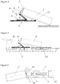
Figure 3 shows a situation in which the container is landing on rear rollers of the loading equipment. -
Figure 4 shows a situation in which the container is transferred to a trailer. -
Figure 5 shows a possible application of at least one distance sensor. -
Figure 6 shows information about the geometry of the loading equipment. -
Figures 7a and 7b show by way of example different possibilities for placement of the stereographic sensor system. -
Figure 8 shows schematically an embodiment of an loading equipment according to the invention. - The figures generally show an embodiment of the invention having a
loading equipment 4 in the form of a hookloader having one or two articulated arms 9 (in the figures only a single articulatedarm 9 is visible) in which is slidably mounted anotherarm 9. Thearms 9 can be moved by at least one actuator, e. g. a hydraulic piston unit. The hookloader is mounted on atruck 7. The loading operation is being accomplished by lifting thecontainer 3 with the hookloader after establishing coupling between afirst coupling device 1 arranged on thecontainer 3 and asecond coupling device 2 in the form of a hook of the hookloader. Astereographic sensor system 6 is provided. - In
Figures 1 to 6 thestereographic sensor system 6 is arranged on anarm 9 of theloading equipment 4 adjacent to the second coupling means 2. Alternative placements are possible. - The features of the invention discussed with respect to the different figures can be used separately or in any desired combination.
- Although not shown in the figures, there could be provided a security device being configured to monitor a work area of the
loading equipment 4 and to give a warning if a person or an obstacle is inside or enters the work area and/or to automatically interrupt operation of theloading equipment 4. -
Figures 1a and 1b show that although the position of thefirst coupling device 1 of acontainer 3 relative to thecontainer 3 itself (absolute height H) is defined by local container standards, due to different placements of thecontainer 3 or the truck-mountedloading equipment 4 the position of thefirst coupling device 1 relative to thesecond coupling device 2 of the loading equipment 4 (relative height h) varies. Thestereographic sensor system 6 allows detection of the position of thefirst coupling device 1 relative to a reference position, e. g. relative to a position of thesecond coupling device 2 and/or relative to a position on thecontainer 3 itself and/or relative to a position of thestereographic sensor system 6.
Figures 2a and 2b show that for a successful loading of thecontainer 3 it is necessary to align thetruck 7 sufficiently collinear to thecontainer 3. Otherwise thecontainer 3 cannot be lifted or may be dropped during the lifting process. This alignment can be also achieved during the first part of the loading process but at the latest at the point where the container rails are landing ontorear rollers 12 of theloading equipment 4 the collinear alignment needs to be achieved. An alignment during the first part of the loading process can be achieved by steering thetruck 7 during the loading procedure, as will be explained in the following paragraph. - The truck driver positions the
truck 7 in front of acontainer 3. Depending on the area where thecontainer 3 is situated, sometimes it is not possible to position thetruck 7 fully aligned with thecontainer 3. The correct way of loading acontainer 3 with a hookloader is to pull or move thetruck 7 underneath the liftedcontainer 3, e. g. by using the force created by the hookloader. By controlling the truck steering during this operation, sufficient alignment betweentruck 7 andcontainer 3 can be achieved. - In the prior art, the operator has to use the mirrors of the
truck 7 to assure this aligned position. Again, this can become a challenge for unexperienced truck drivers. Furthermore, a collision can occur easily. If the misalignment angle α (Figure 2b ) is very large there is also the risk of a collision of thecontainer 3 with parts of thetruck 7 or the hookloader during the lifting movement. Thestereographic sensor system 6 allows the operator to engage with the eyelet by giving information about the position and orientation of thecontainer 3, ensuring a sufficiently collinear alignment oftruck 7 andcontainer 3 before and/or during loading. - In the following description the
first coupling device 1 will, by way of example, be taken to be an eyelet. - It can be provided that a class of the
container 3 can be recognized by the data processor 5 (or thecontrol unit 11 of the loading equipment 4) by calculating the position of thefirst coupling device 1 in relation to a predefined reference position in the form of a predefined point on thecontainer 3, e. g. a distance from an edge, a distance from a center point of an area, etc. This information can be used to check whether thesecond coupling device 2 of the hookloader is compatible for loading or coupling with thefirst coupling device 1. If not, a warning could be given to the operator and/or the height of thesecond coupling device 2 could be adjusted (semi-)automatically by thecontrol unit 11. - It can be provided that the
control unit 11 and/or thedata processor 5 is/are configured to monitor a locking state of loadedcontainer 3. For this it might be necessary to use at least oneadditional sensor 14. - For operations at night it can be necessary to light up the
container 3 in order to provide enough light for thestereographic sensor system 6 to work. This illumination can be provided in the required spectrum, depending on the type ofstereographic sensor system 6. - At the rear end of the truck 7 (the end showing towards the
container 3 before lifting) there can be providedrear rollers 12 for enabling thecontainer 3 to be pulled onto the loading area of the truck 7 (there could be other means to decrease friction between thecontainer 3 and the bed of thetruck 7, e. g. friction-reducing glide pads).Figure 3 shows the situation where the container 3 (more specifically the container rails arranged on the underside of the container 3) is landing on therear rollers 12 of the hookloader. It is in the nature ofhookloader containers 3 that they are produced in different lengths according to their application and customer needs. The design of so called telescopic hookloaders (having at least twoarms 9 one of which is slidingly engaged with the other arm 9) provides for that fact. It allows the operator to position the hookloader as far forward towards thecabin 10 as possible but it is in the operator's responsibility not to pull thecontainer 3 too far forward so that thecontainer 3 would be pulled off therear rollers 12 with its rear end. Once thecontainer 3 passes therear rollers 12 at the end of the loading area and rests directly on the bed of thetruck 7, it cannot be unloaded by the hookloader anymore. Thestereographic sensor system 6 and/or information provided by at least oneadditional sensor 14 can ensure that this situation does not occur. - If it is determined that a rear overhang of the
container 3 is too large thecontrol unit 11 can command automatic deployment of an underrun bumper (not shown, also called underride guard) from a rear end of thetruck 7 to ensure safety and compliance with road regulations. - There are several situations where the
truck 7 can collide easily with thecontainer 3 or other objects around the loading area. The first situation described refers to the situation shown inFigures 1a and 1b . If the position of the hook is not exactly in the right height it will collide with another part of thecontainer 3 if there is no distance measurement system which gives the driver information about the distance to the container. Thestereographic sensor system 6 and/or information provided by at least oneadditional sensor 14 allows to avoid collisions during loading and unloading. - If the
container 3 is not placed on the ground but is transferred to a trailer 13 (cf.Figure 4 ) thetruck 7 needs to get very close to thetrailer 13. Here an exact distance information would be very helpful too. Furthermore, thetruck 7 and thetrailer 13 have to be aligned sufficiently collinear again as shown inFigures 2a and 2b . Thestereographic sensor system 6 allows the operator to ensure a sufficiently collinear alignment oftruck 7 andtrailer 13. - Since a hookloader can be equipped with an articulated
arm 9 there is a risk of collision between thecontainer 3 and the rear end of thetruck 7 since the position of thearm 9 with respect to thetruck 7 itself can vary. There are two collision situations which can occur. The first collision situation occurs if thecontainer 3 is pulled too close to thetruck 7 and is lifted afterwards. Due to the lifting the lower edge of thecontainer 3 moves into the direction of thetruck 7 and collides with the rear end of the same. In the same way a collision situation can happen during the unloading process of thecontainer 3, if the lower edge of thecontainer 3 is still positioned above thetruck 7 but the hook is already moving down vertically. The motivation for pulling thecontainer 3 as close as possible over the back edge of thetruck 7 stems from the desire to keep the loading angle (tip angle or inclination) of thecontainer 3 during the loading and unloading process as small as possible. This is a requirement to avoid movement of parts or loaded goods inside thecontainer 3. In the prior art,control unit 11 of the hookloader does not get information about the current position of the hook because there are no sensors for detecting it. Only the final positions (fully extended or fully retracted) of the hydraulic cylinders can be detected in the prior art. Thestereographic sensor system 6 and/or information provided by at least oneadditional sensor 14 can ensure that the situations described above do not occur. - Tipping is used for unloading the content of the
container 3. For this thecontainer 3 is lifted until the content of thecontainer 3 moves due to gravity. After tipping thecontainer 3 the operator has to check if thecontainer 3 is empty. The invention allows to inspect the content of the container by use of thestereographic sensor system 6. However, this function could also be provided by an additional (2D) camera. - The whole process of loading a
container 3, transporting it to another location and unloading it finally again could be recorded somehow. Important information is the point or duration of time when thecontainer 3 was manipulated, the contents of thecontainer 3 before and after manipulation and the place where the manipulation was done (documentation of manipulation of container 3). The invention allows documentation of the whole manipulation process by use of thestereographic sensor system 6. This documentation can be saved to an electronic memory of thedata processor 5 or thecontrol unit 11 and/or could be sent via a telecommunication device to a predefined receiver (e. g. cloud). -
Figure 5 shows a possible application of at least one additional sensor 14 (e. g. ultrasonic sensor) the signals of which can be transferred to thecontrol unit 11 of theloading equipment 4. In a first application it can be detected if thecontainer 3 is pulled too far. For this theadditional sensor 14 needs to be placed at the or near the rear end of thetruck 7. Preferably,additional sensor 14 is placed at a location inbetween therear rollers 12 and the rear end of thetruck 7. Once thecontainer 3 passes the position of theadditional sensor 14 the output signal allows thecontrol unit 11 of theloading equipment 4 to detect this and give out a warning and/or stop the pulling operation of thecontainer 3. For the second case at least onesensor 14 can be used to detect the distance from thetruck 7 to thecontainer 3. If a pair of twosensors 14 is used, information about collinear alignment oftruck 7 andcontainer 3 can be provided to thecontrol unit 11 of theloading equipment 4. - In the prior art, only the end positions (fully extended or fully retracted) of the
loading equipment 4 are recognized. This can lead to problems during the loading and unloading process (e. g. collisions as discussed above). The information of the current position of thesecond coupling device 2 of the loading equipment 4 (e. g. hook) can be provided to thecontrol unit 11 of theloading equipment 4 by measuring the geometry of the hookloader (the length and angles of thearms 9 and the hook of the hookloader). There is also an influence by the length and position of thecontainer 3 which can be considered to avoid collisions at the rear of thetruck 7. Furthermore, the actual position of thesecond coupling device 2 is a necessary information for any (semi-)autonomous function of theloading equipment 4. Thestereographic sensor system 6 and/or information provided by at least oneadditional sensor 14 can be used for an automatic adjustment of thesecond coupling device 2. -
Figures 7a and 7b show by way of example different possibilities for placement of thestereographic sensor system 6. - For (semi-)autonomous adjusting of the
loading equipment 4 the relative distance and orientation betweensecond coupling device 2 andfirst coupling device 1 of thecontainer 3 is necessary. If thestereographic sensor system 6 is placed directly on anarm 9 of theloading equipment 4 and moves together with it (cf.Figure 7b ), information concerning the position of thesecond coupling device 2 is always available. Therefore, it would be an advantage to place thestereographic sensor system 6 near thesecond coupling device 2. Furthermore, the elevated position of thestereographic sensor system 6 can be an advantage if the contents (or filling level) of thecontainer 3 should be controlled as well. Also, the dimensions of thecontainer 3 can be measured if a view from top can be provided. - On the other hand, for such a placement of the
stereographic sensor system 6 additional functionalities like distance detection or collision avoidance are not possible untill thesecond coupling device 2 is lifted. This information would then have to be provided by at least oneadditional sensor 14 in order to complement the information provided by thestereographic sensor system 6. - Alternative positions of the
stereographic sensor system 6 can be considered. If the system is placed at or near the rear end of the truck 7 (cf.Figure 7a ) it always points in direction of thecontainer 3 while an operator of thetruck 7 moves thetruck 7 backwards towards thecontainer 3. In this case, thestereographic sensor system 6 can be used for the detection of the correct height of thesecond coupling device 2 with respect to thefirst coupling device 1 and/or for measuring the distance betweentruck 7 andcontainer 3 and/or for enlargement of the field of detection and/or to avoid pulling thecontainer 3 too far (past the rear rollers 12) onto a loading area of thetruck 7. Such a placement can also facilitate determination of a rear overhang of thecontainer 3. - Other than shown in
Figures 7a and 7b , thestereographic sensor system 6 could also be placed on an elevated position on thetruck 7, e. g. on acabin 10 of thetruck 7, in a position where the field of detection is sufficient. - The
stereographic sensor sytem 6 could be placed on a mounting that can be moved relative to thetruck 7 or theloading equipment 4, e. g. by changing elevation and/or angular position and/or inclination of thestereographic sensor system 6. -
Figure 8 schematically shows an embodiment of aloading equipment 4 according to the invention. Adata processor 5 receives data from thestereographic sensor system 6 and from at least oneadditional sensor 14 regarding a container 3 (e. g. position offirst coupling device 1, length ofcontainer 3, width ofcontainer 3, height ofcontainer 3, load of container 3) and/or thesecond coupling device 2 and/or anarm 9 of theloading equipment 4. Thedata processor 5 can provide this data to acontrol unit 11 of the loading equipment 4 (alternatively thecontrol unit 11 itself could comprise the data processor 5). - Depending on the position of the
stereographic sensor system 6 relative to theloading equipment 4 or thetruck 7, thestereographic sensor system 6 can provide thedata processor 5 or thecontrol unit 11, respectively, with information about the position of thefirst coupling device 1 on thecontainer 3 and/or the position and dimensions of thecontainer 3 and/or the position of thesecond coupling device 2. Based on this data, movement of thesecond coupling device 2 can be controlled by thecontrol unit 11 by way ofactuators 15 of theloading equipment 4, e. g. by controlling flow of hydraulic fluid and/or pressure of hydraulic fluid to and/or from at least one cylinder used to move at least onearm 9 of theloading equipment 4.
Claims (18)
- Truck-mountable detection system for detection of a first coupling device (1) of a container (3), the first coupling device (1) being configured for coupling with a second coupling device (2) of a truck-mounted loading equipment (4), in particular a hook of a hookloader, the detection system having a data processor (5) and an data capturing device the data of which can be sent to the data processor (5), characterized in that the data capturing device is a stereographic sensor system (6) and the data processor (5) is configured to automatically recognize the shape of the first coupling device (1) of the container (3) based on the data provided by the stereographic sensor system (6).
- Truck-mountable detection system according to claim 1, wherein the stereographic sensor system comprises at least two sensors looking at the same field of detection, preferably at least two cameras.
- Truck-mountable detection system according to at least one of the preceding claims, wherein the position of the automatically recognized first coupling device (1) is calculated.
- Truck-mountable detection system according to at least one of the preceding claims, wherein the data processor (5) is configured to check whether the second coupling device (2) is compatible for coupling and loading with the first coupling device (1) based on the data provided by the stereographic sensor system (6).
- Truck-mountable detection system according to at least one of the preceding claims, wherein a class of the container (3) can be recognized by the data processor (5) by calculating the position of the first coupling device (1) in relation to a predefined reference position in the form of a predefined point on the container (3).
- Truck-mountable loading equipment (4), in particular hookloader, having a truck-mountable detection system according to at least one of the preceding claims, and a second coupling device (2) which is configured for coupling with a first coupling device (1) of a container (3), wherein the data processor (5) of the detection system is implemented by a control unit (11) of the loading equipment (4) or is connected to a control unit (11) of the loading equipment (4).
- Truck-mountable loading equipment (4) according to the preceding claim, wherein the control unit (11) of the loading equipment (4) is configured to calculate a desired trajectory and/or an actual trajectory of a motion of the loading equipment (4) based on the data provided by the stereographic sensor system (6) and/or based on data provided by at least one sensor (14) different from the stereographic sensor system (6).
- Truck-mountable loading equipment (4) according to at least one of the preceding claims, wherein the control unit (11) of the loading equipment (4) is configured to automatically compute the position of a container (3) relative to the loading equipment (4) based on the data provided by the stereographic sensor system (6) and/or based on data provided by at least one sensor (14) different from the stereographic sensor system (6).
- Truck-mountable loading equipment (4) according to at least one of the preceding claims, wherein the control unit (11) of the loading equipment (4) is configured to automatically detect a shape of the container (3) based on the data provided by the stereographic sensor system (6).
- Truck-mountable loading equipment (4) according to at least one of the preceding claims, wherein the control unit (11) of the loading equipment (4) is configured to give information about alignment of truck (7) and/or a trailer (13) and/or container (3) to an operator of the loading equipment (4) based on the data provided by the stereographic sensor system (6) and/or based on data provided by at least one sensor (14) different from the stereographic sensor system (6) before and/or during loading.
- Truck-mountable loading equipment (4) according to at least one of the preceding claims, wherein the control unit (11) of the loading equipment (4) is configured to automatically determine a rear end position of a container (3) and to detect if a container (3) is short and is in danger of being pulled too far onto a loading area of the truck (7) and/or to detect if a container (3) is long would stick out too far over the rear end of the truck (7) based on the data provided by the stereographic sensor system (6) and/or based on data provided by at least one sensor (14) different from the stereographic sensor system (6) and wherein it is preferably provided that in case the container (3) is detected to be long an underrun bumper is being deployed automatically.
- Truck-mountable loading equipment (4) according to at least one of the preceding claims, wherein the control unit (11) of the loading equipment (4) is configured to automatically couple and/or decouple the second coupling device (2) of the container (3) and the first coupling device (1) of the loading equipment (4) based on the position of the first coupling device (1) calculated by the detection system, wherein the control unit (11) automatically or semi-automatically commands movements of the loading equipment (4) for the automatic coupling and/or decoupling.
- Truck-mountable loading equipment (4) according to at least one of the preceding claims, wherein the control unit (11) of the loading equipment (4) is configured to automatically or semi-automatically load and/or automatically or semi-automatically unload a container (3) by commanding movements of the loading equipment (4) based on the data provided by the stereographic sensor system (6) and/or based on data provided by at least one sensor (14) different from the stereographic sensor system (6), wherein it is preferably provided that driving operations of the truck (7) are being controlled by a driver of the truck (7).
- Truck-mountable loading equipment (4) according to at least one of the preceding claims, wherein there is provided a security device being configured to monitor a work area of the loading equipment (4) and to give a warning if a person or an obstacle is inside or enters the work area and/or to automatically interrupt operation of the loading equipment (4).
- Truck-mountable loading equipment (4) according to at least one of the preceding claims, wherein there is provided a display (8) for displaying data provided by the stereographic sensor system (6) and/or wherein it is preferably provided that additional information regarding a loading and/or unloading process of a container (3) provided by an at least one additional sensor (14) is being displayed on the display (8) together with the data provided by the stereographic sensor system (6).
- Truck-mountable loading equipment (4) according to at least one of the preceding claims, wherein the loading equipment (4) is a hookloader being preferably equipped with an articulated arm (9) and/or being preferably a telescopic hookloader.
- Truck (7) on which is mounted:- a detection system according to at least one of the claims 1 to 5 and- a loading equipment (4), in particular a hookloader, having a second coupling device (2) which is configured for coupling with a first coupling device (1) of a container (3), in particular according to one of claims 6 to 16.
- Truck (7) according to the preceding claim, wherein the stereographic sensor system (6) is
either mounted on or to- at or near a rear end of the truck (7), or- an arm (9) of the loading equipment (4) or- in an elevated position on the truck, preferably on a cabin (10) of the truck (7)or the stereographic sensor system (6) is mounted on a vehicle which is moveable separately from the truck (7).
Priority Applications (7)
| Application Number | Priority Date | Filing Date | Title |
|---|---|---|---|
| PL17205429T PL3495202T3 (en) | 2017-12-05 | 2017-12-05 | Truck-mountable detection system |
| ES17205429T ES2828307T3 (en) | 2017-12-05 | 2017-12-05 | Detection system for truck mounting |
| EP17205429.8A EP3495202B1 (en) | 2017-12-05 | 2017-12-05 | Truck-mountable detection system |
| KR1020207015800A KR102339268B1 (en) | 2017-12-05 | 2018-11-23 | Truck Mountable Detection System |
| PCT/EP2018/082406 WO2019110330A1 (en) | 2017-12-05 | 2018-11-23 | Truck-mountable detection system |
| JP2020549873A JP7026816B2 (en) | 2017-12-05 | 2018-11-23 | Truck mountable detection system |
| US16/891,359 US11685302B2 (en) | 2017-12-05 | 2020-06-03 | Truck-mountable detection system |
Applications Claiming Priority (1)
| Application Number | Priority Date | Filing Date | Title |
|---|---|---|---|
| EP17205429.8A EP3495202B1 (en) | 2017-12-05 | 2017-12-05 | Truck-mountable detection system |
Publications (2)
| Publication Number | Publication Date |
|---|---|
| EP3495202A1 true EP3495202A1 (en) | 2019-06-12 |
| EP3495202B1 EP3495202B1 (en) | 2020-08-19 |
Family
ID=60627446
Family Applications (1)
| Application Number | Title | Priority Date | Filing Date |
|---|---|---|---|
| EP17205429.8A Active EP3495202B1 (en) | 2017-12-05 | 2017-12-05 | Truck-mountable detection system |
Country Status (7)
| Country | Link |
|---|---|
| US (1) | US11685302B2 (en) |
| EP (1) | EP3495202B1 (en) |
| JP (1) | JP7026816B2 (en) |
| KR (1) | KR102339268B1 (en) |
| ES (1) | ES2828307T3 (en) |
| PL (1) | PL3495202T3 (en) |
| WO (1) | WO2019110330A1 (en) |
Cited By (1)
| Publication number | Priority date | Publication date | Assignee | Title |
|---|---|---|---|---|
| EP3756947A1 (en) * | 2019-06-24 | 2020-12-30 | Cargotec Patenter AB | A working unit comprising a vehicle, a working equipment, and a method in relation to a working unit |
Families Citing this family (9)
| Publication number | Priority date | Publication date | Assignee | Title |
|---|---|---|---|---|
| JP7210369B2 (en) * | 2018-04-27 | 2023-01-23 | 新明和工業株式会社 | work vehicle |
| US11708252B2 (en) * | 2019-07-19 | 2023-07-25 | United States Postal Service | Automated hitch for automated vehicle |
| JP7614895B2 (en) * | 2021-03-18 | 2025-01-16 | 極東開発工業株式会社 | Cargo handling vehicles and loading equipment |
| JP2023020975A (en) * | 2021-07-29 | 2023-02-09 | 極東開発工業株式会社 | cargo handling vehicle |
| US12449546B2 (en) * | 2022-04-15 | 2025-10-21 | Zebra Technologies Corporation | Lidar sensor system for enabling or disabling use of a robotic arm |
| CN116353461A (en) * | 2023-03-16 | 2023-06-30 | 三一环境产业有限公司 | Vehicle automatic coupling system and coupling method thereof |
| CN117842682A (en) * | 2023-10-26 | 2024-04-09 | 中联恒通机械有限公司 | Container loading control method |
| CN117124966B (en) * | 2023-10-26 | 2024-01-12 | 龙合智能装备制造有限公司 | A multifunctional integrated self-loading and unloading truck |
| CN121157770B (en) * | 2025-11-10 | 2026-02-27 | 南京金长江交通设施有限公司 | A mother-and-child type drainage emergency vehicle |
Citations (4)
| Publication number | Priority date | Publication date | Assignee | Title |
|---|---|---|---|---|
| DE102010006323A1 (en) | 2010-01-29 | 2011-08-04 | Continental Teves AG & Co. OHG, 60488 | Stereo camera for detecting angle and/or position of trailer attached to motor vehicle, arranged at rear-side of vehicle to determine position and/or angle of trailer attached to vehicle by object detection algorithm based images of camera |
| US20150249821A1 (en) | 2012-09-21 | 2015-09-03 | Tadano Ltd. | Surrounding information-obtaining device for working vehicle |
| EP3153348A1 (en) | 2015-10-05 | 2017-04-12 | Franz Xaver Meiller Fahrzeug- und Maschinenfabrik - GmbH & Co KG | Load transport vehicle with monitoring means for secure handling of a swappable container |
| WO2017108764A1 (en) | 2015-12-22 | 2017-06-29 | Hyva Holding B.V. | Guidance system and method for providing guidance |
Family Cites Families (33)
| Publication number | Priority date | Publication date | Assignee | Title |
|---|---|---|---|---|
| JPS58177295A (en) * | 1982-04-07 | 1983-10-17 | 株式会社日立製作所 | robot control device |
| WO1992017287A2 (en) * | 1991-03-29 | 1992-10-15 | Csx Transportation, Inc. | Device to uniquely recognize travelling containers |
| NL194669C (en) * | 1994-03-11 | 2002-11-04 | Tts Mongstad As | System for loading and unloading cargo units in cargo vessels. |
| JPH11300670A (en) * | 1998-04-21 | 1999-11-02 | Fanuc Ltd | Article picking-up device |
| JP4739569B2 (en) | 2001-04-09 | 2011-08-03 | パナソニック株式会社 | Driving assistance device |
| JP3483143B2 (en) | 2001-04-09 | 2004-01-06 | 松下電器産業株式会社 | Driving support device |
| WO2004020938A1 (en) * | 2002-08-27 | 2004-03-11 | Dralle Aps | A method and a system for automatic measurement and tracking of logs, industrial wood and boards |
| US7822264B2 (en) * | 2003-08-15 | 2010-10-26 | Scape A/S | Computer-vision system for classification and spatial localization of bounded 3D-objects |
| US8998555B1 (en) * | 2005-05-06 | 2015-04-07 | Little Giant Refuse Vehicle, LLC | Lightweight waste gathering and disposal vehicle with automated arm |
| US20070140821A1 (en) * | 2005-12-19 | 2007-06-21 | Betzalel Robotics, Llc | Autonomous load/unload robot |
| US8915692B2 (en) * | 2008-02-21 | 2014-12-23 | Harvest Automation, Inc. | Adaptable container handling system |
| US8306314B2 (en) * | 2009-12-28 | 2012-11-06 | Mitsubishi Electric Research Laboratories, Inc. | Method and system for determining poses of objects |
| US8908913B2 (en) * | 2011-12-19 | 2014-12-09 | Mitsubishi Electric Research Laboratories, Inc. | Voting-based pose estimation for 3D sensors |
| WO2014024336A1 (en) * | 2012-08-09 | 2014-02-13 | トヨタ自動車株式会社 | Object detection apparatus and driving assistance apparatus |
| EP2698596A1 (en) * | 2012-08-16 | 2014-02-19 | Hexagon Technology Center GmbH | Method and system for determining spatial coordinates with a mobile coordinate measuring machine |
| US9233470B1 (en) * | 2013-03-15 | 2016-01-12 | Industrial Perception, Inc. | Determining a virtual representation of an environment by projecting texture patterns |
| US9650215B2 (en) * | 2013-05-17 | 2017-05-16 | Intelligrated Headquarters Llc | Robotic carton unloader |
| US9452531B2 (en) * | 2014-02-04 | 2016-09-27 | Microsoft Technology Licensing, Llc | Controlling a robot in the presence of a moving object |
| JP6324203B2 (en) * | 2014-05-14 | 2018-05-16 | キヤノン株式会社 | Information processing apparatus, control method therefor, program, and recording medium |
| JP6397226B2 (en) * | 2014-06-05 | 2018-09-26 | キヤノン株式会社 | Apparatus, apparatus control method, and program |
| JP6385745B2 (en) * | 2014-07-22 | 2018-09-05 | 日立建機株式会社 | Mining work vehicle |
| EP3002550B1 (en) * | 2014-10-03 | 2017-08-30 | Ricoh Company, Ltd. | Information processing system and information processing method for distance measurement |
| US9945092B2 (en) * | 2014-12-19 | 2018-04-17 | Ulc Robotics, Inc. | System and method for utility maintenance |
| JP2016203836A (en) | 2015-04-24 | 2016-12-08 | 日立建機株式会社 | Vehicle and application system for transportation vehicle for mine |
| US11176286B2 (en) * | 2015-09-09 | 2021-11-16 | Xerox Corporation | System and method for internal structural defect analysis using three-dimensional sensor data |
| JP2017076833A (en) | 2015-10-13 | 2017-04-20 | アルパイン株式会社 | Driving support device and computer program |
| JP6716411B2 (en) * | 2015-10-22 | 2020-07-01 | 新明和工業株式会社 | Container handling vehicle |
| US10002431B2 (en) * | 2015-11-03 | 2018-06-19 | The Boeing Company | Locating a feature for robotic guidance |
| JP6496671B2 (en) * | 2016-01-13 | 2019-04-03 | 株式会社ぐるなび | Information processing apparatus, terminal apparatus, information processing method, and program |
| US9908696B1 (en) * | 2016-09-08 | 2018-03-06 | X Development Llc | Pallet-conveyor system |
| US10792809B2 (en) * | 2017-12-12 | 2020-10-06 | X Development Llc | Robot grip detection using non-contact sensors |
| CN112004695B (en) * | 2018-02-21 | 2024-09-06 | 奥特莱德科技公司 | Systems and methods for automated operation and handling of autonomous trucks and tractor trailers |
| US10671835B2 (en) * | 2018-03-05 | 2020-06-02 | Hong Kong Applied Science And Technology Research Institute Co., Ltd. | Object recognition |
-
2017
- 2017-12-05 PL PL17205429T patent/PL3495202T3/en unknown
- 2017-12-05 EP EP17205429.8A patent/EP3495202B1/en active Active
- 2017-12-05 ES ES17205429T patent/ES2828307T3/en active Active
-
2018
- 2018-11-23 KR KR1020207015800A patent/KR102339268B1/en active Active
- 2018-11-23 WO PCT/EP2018/082406 patent/WO2019110330A1/en not_active Ceased
- 2018-11-23 JP JP2020549873A patent/JP7026816B2/en active Active
-
2020
- 2020-06-03 US US16/891,359 patent/US11685302B2/en active Active
Patent Citations (4)
| Publication number | Priority date | Publication date | Assignee | Title |
|---|---|---|---|---|
| DE102010006323A1 (en) | 2010-01-29 | 2011-08-04 | Continental Teves AG & Co. OHG, 60488 | Stereo camera for detecting angle and/or position of trailer attached to motor vehicle, arranged at rear-side of vehicle to determine position and/or angle of trailer attached to vehicle by object detection algorithm based images of camera |
| US20150249821A1 (en) | 2012-09-21 | 2015-09-03 | Tadano Ltd. | Surrounding information-obtaining device for working vehicle |
| EP3153348A1 (en) | 2015-10-05 | 2017-04-12 | Franz Xaver Meiller Fahrzeug- und Maschinenfabrik - GmbH & Co KG | Load transport vehicle with monitoring means for secure handling of a swappable container |
| WO2017108764A1 (en) | 2015-12-22 | 2017-06-29 | Hyva Holding B.V. | Guidance system and method for providing guidance |
Non-Patent Citations (1)
| Title |
|---|
| ANONYMOUS: "Contrinex Blog: Rugged Inductive Sensors Detect Position of Demountable Container on Hooklift Trucks", VALIN, 19 April 2016 (2016-04-19), pages 2pp, XP055610899 |
Cited By (2)
| Publication number | Priority date | Publication date | Assignee | Title |
|---|---|---|---|---|
| EP3756947A1 (en) * | 2019-06-24 | 2020-12-30 | Cargotec Patenter AB | A working unit comprising a vehicle, a working equipment, and a method in relation to a working unit |
| US11235692B2 (en) | 2019-06-24 | 2022-02-01 | Hiab Ab | Working unit, a working equipment, and a method in relation to a working unit |
Also Published As
| Publication number | Publication date |
|---|---|
| US20200290496A1 (en) | 2020-09-17 |
| WO2019110330A1 (en) | 2019-06-13 |
| KR102339268B1 (en) | 2021-12-14 |
| KR20200096524A (en) | 2020-08-12 |
| EP3495202B1 (en) | 2020-08-19 |
| PL3495202T3 (en) | 2021-02-08 |
| ES2828307T3 (en) | 2021-05-26 |
| JP2021505479A (en) | 2021-02-18 |
| US11685302B2 (en) | 2023-06-27 |
| JP7026816B2 (en) | 2022-02-28 |
Similar Documents
| Publication | Publication Date | Title |
|---|---|---|
| US11685302B2 (en) | Truck-mountable detection system | |
| EP1834922B1 (en) | Industrial truck with a mast | |
| JP4250151B2 (en) | System for connecting trailers to automobiles | |
| JP7103077B2 (en) | Remote control system for forklifts | |
| CA2810581C (en) | Collision detection and mitigation systems and methods for a shovel | |
| US10315697B2 (en) | Vehicle comprising a manoeuvring system | |
| CN105531996B (en) | Obstacle detection device for working machinery | |
| EP3000771A1 (en) | Fork-lift truck | |
| US20080011554A1 (en) | Movable sensor device on the loading means of a forklift | |
| CN116888063A (en) | Smart warehouse security mechanism | |
| EP3209509B1 (en) | Coupling assist system for a tractor trailer | |
| US20140232871A1 (en) | Method for manually calibrating a camera mounted on vehicle | |
| CN117881554A (en) | Autonomous trailer maneuvering | |
| EP3393852B1 (en) | Guidance system and method for providing guidance | |
| JP7363308B2 (en) | Outrigger device and work vehicle | |
| CN115341614A (en) | System and method for assisting in positioning a transport vehicle relative to a work machine | |
| JPWO2020059842A1 (en) | Container crane equipment and control method of container crane equipment | |
| FI3153348T4 (en) | Load transport vehicle with monitoring means for secure handling of a swappable container | |
| US11235692B2 (en) | Working unit, a working equipment, and a method in relation to a working unit | |
| US12304463B2 (en) | Airport vehicle having an anti-collision system and method for operating a vehicle having an anti-collision system | |
| US20250024772A1 (en) | System and method providing load and implement verification | |
| CN118348517A (en) | AGV retreating distance detection feedback system |
Legal Events
| Date | Code | Title | Description |
|---|---|---|---|
| PUAI | Public reference made under article 153(3) epc to a published international application that has entered the european phase |
Free format text: ORIGINAL CODE: 0009012 |
|
| STAA | Information on the status of an ep patent application or granted ep patent |
Free format text: STATUS: THE APPLICATION HAS BEEN PUBLISHED |
|
| AK | Designated contracting states |
Kind code of ref document: A1 Designated state(s): AL AT BE BG CH CY CZ DE DK EE ES FI FR GB GR HR HU IE IS IT LI LT LU LV MC MK MT NL NO PL PT RO RS SE SI SK SM TR |
|
| AX | Request for extension of the european patent |
Extension state: BA ME |
|
| STAA | Information on the status of an ep patent application or granted ep patent |
Free format text: STATUS: REQUEST FOR EXAMINATION WAS MADE |
|
| 17P | Request for examination filed |
Effective date: 20191017 |
|
| RBV | Designated contracting states (corrected) |
Designated state(s): AL AT BE BG CH CY CZ DE DK EE ES FI FR GB GR HR HU IE IS IT LI LT LU LV MC MK MT NL NO PL PT RO RS SE SI SK SM TR |
|
| GRAP | Despatch of communication of intention to grant a patent |
Free format text: ORIGINAL CODE: EPIDOSNIGR1 |
|
| STAA | Information on the status of an ep patent application or granted ep patent |
Free format text: STATUS: GRANT OF PATENT IS INTENDED |
|
| INTG | Intention to grant announced |
Effective date: 20200318 |
|
| GRAS | Grant fee paid |
Free format text: ORIGINAL CODE: EPIDOSNIGR3 |
|
| GRAJ | Information related to disapproval of communication of intention to grant by the applicant or resumption of examination proceedings by the epo deleted |
Free format text: ORIGINAL CODE: EPIDOSDIGR1 |
|
| GRAL | Information related to payment of fee for publishing/printing deleted |
Free format text: ORIGINAL CODE: EPIDOSDIGR3 |
|
| STAA | Information on the status of an ep patent application or granted ep patent |
Free format text: STATUS: REQUEST FOR EXAMINATION WAS MADE |
|
| TPAC | Observations filed by third parties |
Free format text: ORIGINAL CODE: EPIDOSNTIPA |
|
| GRAR | Information related to intention to grant a patent recorded |
Free format text: ORIGINAL CODE: EPIDOSNIGR71 |
|
| STAA | Information on the status of an ep patent application or granted ep patent |
Free format text: STATUS: GRANT OF PATENT IS INTENDED |
|
| GRAA | (expected) grant |
Free format text: ORIGINAL CODE: 0009210 |
|
| STAA | Information on the status of an ep patent application or granted ep patent |
Free format text: STATUS: THE PATENT HAS BEEN GRANTED |
|
| INTC | Intention to grant announced (deleted) | ||
| AK | Designated contracting states |
Kind code of ref document: B1 Designated state(s): AL AT BE BG CH CY CZ DE DK EE ES FI FR GB GR HR HU IE IS IT LI LT LU LV MC MK MT NL NO PL PT RO RS SE SI SK SM TR |
|
| INTG | Intention to grant announced |
Effective date: 20200714 |
|
| REG | Reference to a national code |
Ref country code: CH Ref legal event code: EP |
|
| REG | Reference to a national code |
Ref country code: DE Ref legal event code: R096 Ref document number: 602017021864 Country of ref document: DE |
|
| REG | Reference to a national code |
Ref country code: AT Ref legal event code: REF Ref document number: 1303577 Country of ref document: AT Kind code of ref document: T Effective date: 20200915 |
|
| REG | Reference to a national code |
Ref country code: IE Ref legal event code: FG4D |
|
| REG | Reference to a national code |
Ref country code: CH Ref legal event code: NV Representative=s name: ISLER AND PEDRAZZINI AG, CH |
|
| REG | Reference to a national code |
Ref country code: SE Ref legal event code: TRGR |
|
| REG | Reference to a national code |
Ref country code: NL Ref legal event code: FP |
|
| REG | Reference to a national code |
Ref country code: LT Ref legal event code: MG4D |
|
| PG25 | Lapsed in a contracting state [announced via postgrant information from national office to epo] |
Ref country code: PT Free format text: LAPSE BECAUSE OF FAILURE TO SUBMIT A TRANSLATION OF THE DESCRIPTION OR TO PAY THE FEE WITHIN THE PRESCRIBED TIME-LIMIT Effective date: 20201221 Ref country code: LT Free format text: LAPSE BECAUSE OF FAILURE TO SUBMIT A TRANSLATION OF THE DESCRIPTION OR TO PAY THE FEE WITHIN THE PRESCRIBED TIME-LIMIT Effective date: 20200819 Ref country code: HR Free format text: LAPSE BECAUSE OF FAILURE TO SUBMIT A TRANSLATION OF THE DESCRIPTION OR TO PAY THE FEE WITHIN THE PRESCRIBED TIME-LIMIT Effective date: 20200819 Ref country code: NO Free format text: LAPSE BECAUSE OF FAILURE TO SUBMIT A TRANSLATION OF THE DESCRIPTION OR TO PAY THE FEE WITHIN THE PRESCRIBED TIME-LIMIT Effective date: 20201119 Ref country code: FI Free format text: LAPSE BECAUSE OF FAILURE TO SUBMIT A TRANSLATION OF THE DESCRIPTION OR TO PAY THE FEE WITHIN THE PRESCRIBED TIME-LIMIT Effective date: 20200819 Ref country code: GR Free format text: LAPSE BECAUSE OF FAILURE TO SUBMIT A TRANSLATION OF THE DESCRIPTION OR TO PAY THE FEE WITHIN THE PRESCRIBED TIME-LIMIT Effective date: 20201120 Ref country code: BG Free format text: LAPSE BECAUSE OF FAILURE TO SUBMIT A TRANSLATION OF THE DESCRIPTION OR TO PAY THE FEE WITHIN THE PRESCRIBED TIME-LIMIT Effective date: 20201119 |
|
| PG25 | Lapsed in a contracting state [announced via postgrant information from national office to epo] |
Ref country code: RS Free format text: LAPSE BECAUSE OF FAILURE TO SUBMIT A TRANSLATION OF THE DESCRIPTION OR TO PAY THE FEE WITHIN THE PRESCRIBED TIME-LIMIT Effective date: 20200819 Ref country code: LV Free format text: LAPSE BECAUSE OF FAILURE TO SUBMIT A TRANSLATION OF THE DESCRIPTION OR TO PAY THE FEE WITHIN THE PRESCRIBED TIME-LIMIT Effective date: 20200819 Ref country code: IS Free format text: LAPSE BECAUSE OF FAILURE TO SUBMIT A TRANSLATION OF THE DESCRIPTION OR TO PAY THE FEE WITHIN THE PRESCRIBED TIME-LIMIT Effective date: 20201219 |
|
| PG25 | Lapsed in a contracting state [announced via postgrant information from national office to epo] |
Ref country code: EE Free format text: LAPSE BECAUSE OF FAILURE TO SUBMIT A TRANSLATION OF THE DESCRIPTION OR TO PAY THE FEE WITHIN THE PRESCRIBED TIME-LIMIT Effective date: 20200819 Ref country code: SM Free format text: LAPSE BECAUSE OF FAILURE TO SUBMIT A TRANSLATION OF THE DESCRIPTION OR TO PAY THE FEE WITHIN THE PRESCRIBED TIME-LIMIT Effective date: 20200819 Ref country code: DK Free format text: LAPSE BECAUSE OF FAILURE TO SUBMIT A TRANSLATION OF THE DESCRIPTION OR TO PAY THE FEE WITHIN THE PRESCRIBED TIME-LIMIT Effective date: 20200819 Ref country code: RO Free format text: LAPSE BECAUSE OF FAILURE TO SUBMIT A TRANSLATION OF THE DESCRIPTION OR TO PAY THE FEE WITHIN THE PRESCRIBED TIME-LIMIT Effective date: 20200819 |
|
| REG | Reference to a national code |
Ref country code: DE Ref legal event code: R097 Ref document number: 602017021864 Country of ref document: DE |
|
| REG | Reference to a national code |
Ref country code: ES Ref legal event code: FG2A Ref document number: 2828307 Country of ref document: ES Kind code of ref document: T3 Effective date: 20210526 |
|
| PG25 | Lapsed in a contracting state [announced via postgrant information from national office to epo] |
Ref country code: AL Free format text: LAPSE BECAUSE OF FAILURE TO SUBMIT A TRANSLATION OF THE DESCRIPTION OR TO PAY THE FEE WITHIN THE PRESCRIBED TIME-LIMIT Effective date: 20200819 |
|
| PLBE | No opposition filed within time limit |
Free format text: ORIGINAL CODE: 0009261 |
|
| STAA | Information on the status of an ep patent application or granted ep patent |
Free format text: STATUS: NO OPPOSITION FILED WITHIN TIME LIMIT |
|
| PG25 | Lapsed in a contracting state [announced via postgrant information from national office to epo] |
Ref country code: SK Free format text: LAPSE BECAUSE OF FAILURE TO SUBMIT A TRANSLATION OF THE DESCRIPTION OR TO PAY THE FEE WITHIN THE PRESCRIBED TIME-LIMIT Effective date: 20200819 |
|
| 26N | No opposition filed |
Effective date: 20210520 |
|
| PG25 | Lapsed in a contracting state [announced via postgrant information from national office to epo] |
Ref country code: MC Free format text: LAPSE BECAUSE OF FAILURE TO SUBMIT A TRANSLATION OF THE DESCRIPTION OR TO PAY THE FEE WITHIN THE PRESCRIBED TIME-LIMIT Effective date: 20200819 Ref country code: SI Free format text: LAPSE BECAUSE OF FAILURE TO SUBMIT A TRANSLATION OF THE DESCRIPTION OR TO PAY THE FEE WITHIN THE PRESCRIBED TIME-LIMIT Effective date: 20200819 |
|
| PG25 | Lapsed in a contracting state [announced via postgrant information from national office to epo] |
Ref country code: LU Free format text: LAPSE BECAUSE OF NON-PAYMENT OF DUE FEES Effective date: 20201205 Ref country code: IE Free format text: LAPSE BECAUSE OF NON-PAYMENT OF DUE FEES Effective date: 20201205 |
|
| PG25 | Lapsed in a contracting state [announced via postgrant information from national office to epo] |
Ref country code: TR Free format text: LAPSE BECAUSE OF FAILURE TO SUBMIT A TRANSLATION OF THE DESCRIPTION OR TO PAY THE FEE WITHIN THE PRESCRIBED TIME-LIMIT Effective date: 20200819 Ref country code: MT Free format text: LAPSE BECAUSE OF FAILURE TO SUBMIT A TRANSLATION OF THE DESCRIPTION OR TO PAY THE FEE WITHIN THE PRESCRIBED TIME-LIMIT Effective date: 20200819 Ref country code: CY Free format text: LAPSE BECAUSE OF FAILURE TO SUBMIT A TRANSLATION OF THE DESCRIPTION OR TO PAY THE FEE WITHIN THE PRESCRIBED TIME-LIMIT Effective date: 20200819 |
|
| PG25 | Lapsed in a contracting state [announced via postgrant information from national office to epo] |
Ref country code: MK Free format text: LAPSE BECAUSE OF FAILURE TO SUBMIT A TRANSLATION OF THE DESCRIPTION OR TO PAY THE FEE WITHIN THE PRESCRIBED TIME-LIMIT Effective date: 20200819 |
|
| REG | Reference to a national code |
Ref country code: CH Ref legal event code: U11 Free format text: ST27 STATUS EVENT CODE: U-0-0-U10-U11 (AS PROVIDED BY THE NATIONAL OFFICE) Effective date: 20260101 |
|
| PGFP | Annual fee paid to national office [announced via postgrant information from national office to epo] |
Ref country code: GB Payment date: 20251223 Year of fee payment: 9 |
|
| PGFP | Annual fee paid to national office [announced via postgrant information from national office to epo] |
Ref country code: AT Payment date: 20251223 Year of fee payment: 9 |
|
| PGFP | Annual fee paid to national office [announced via postgrant information from national office to epo] |
Ref country code: IT Payment date: 20251218 Year of fee payment: 9 |
|
| PGFP | Annual fee paid to national office [announced via postgrant information from national office to epo] |
Ref country code: NL Payment date: 20251222 Year of fee payment: 9 Ref country code: FR Payment date: 20251223 Year of fee payment: 9 |
|
| PGFP | Annual fee paid to national office [announced via postgrant information from national office to epo] |
Ref country code: BE Payment date: 20251231 Year of fee payment: 9 |
|
| PGFP | Annual fee paid to national office [announced via postgrant information from national office to epo] |
Ref country code: SE Payment date: 20251222 Year of fee payment: 9 |
|
| PGFP | Annual fee paid to national office [announced via postgrant information from national office to epo] |
Ref country code: CZ Payment date: 20251124 Year of fee payment: 9 |
|
| PGFP | Annual fee paid to national office [announced via postgrant information from national office to epo] |
Ref country code: PL Payment date: 20251113 Year of fee payment: 9 |
|
| PGFP | Annual fee paid to national office [announced via postgrant information from national office to epo] |
Ref country code: ES Payment date: 20260122 Year of fee payment: 9 |
|
| PGFP | Annual fee paid to national office [announced via postgrant information from national office to epo] |
Ref country code: DE Payment date: 20251229 Year of fee payment: 9 |
|
| PGFP | Annual fee paid to national office [announced via postgrant information from national office to epo] |
Ref country code: CH Payment date: 20260101 Year of fee payment: 9 |