EP3495191B1 - Heating device for a traction battery of a vehicle, and vehicle having the same - Google Patents
Heating device for a traction battery of a vehicle, and vehicle having the same Download PDFInfo
- Publication number
- EP3495191B1 EP3495191B1 EP17205873.7A EP17205873A EP3495191B1 EP 3495191 B1 EP3495191 B1 EP 3495191B1 EP 17205873 A EP17205873 A EP 17205873A EP 3495191 B1 EP3495191 B1 EP 3495191B1
- Authority
- EP
- European Patent Office
- Prior art keywords
- traction battery
- vehicle
- heating device
- battery
- heating
- Prior art date
- Legal status (The legal status is an assumption and is not a legal conclusion. Google has not performed a legal analysis and makes no representation as to the accuracy of the status listed.)
- Active
Links
Images

Classifications
-
- B—PERFORMING OPERATIONS; TRANSPORTING
- B60—VEHICLES IN GENERAL
- B60L—PROPULSION OF ELECTRICALLY-PROPELLED VEHICLES; SUPPLYING ELECTRIC POWER FOR AUXILIARY EQUIPMENT OF ELECTRICALLY-PROPELLED VEHICLES; ELECTRODYNAMIC BRAKE SYSTEMS FOR VEHICLES IN GENERAL; MAGNETIC SUSPENSION OR LEVITATION FOR VEHICLES; MONITORING OPERATING VARIABLES OF ELECTRICALLY-PROPELLED VEHICLES; ELECTRIC SAFETY DEVICES FOR ELECTRICALLY-PROPELLED VEHICLES
- B60L58/00—Methods or circuit arrangements for monitoring or controlling batteries or fuel cells, specially adapted for electric vehicles
- B60L58/10—Methods or circuit arrangements for monitoring or controlling batteries or fuel cells, specially adapted for electric vehicles for monitoring or controlling batteries
- B60L58/24—Methods or circuit arrangements for monitoring or controlling batteries or fuel cells, specially adapted for electric vehicles for monitoring or controlling batteries for controlling the temperature of batteries
- B60L58/27—Methods or circuit arrangements for monitoring or controlling batteries or fuel cells, specially adapted for electric vehicles for monitoring or controlling batteries for controlling the temperature of batteries by heating
-
- B—PERFORMING OPERATIONS; TRANSPORTING
- B60—VEHICLES IN GENERAL
- B60L—PROPULSION OF ELECTRICALLY-PROPELLED VEHICLES; SUPPLYING ELECTRIC POWER FOR AUXILIARY EQUIPMENT OF ELECTRICALLY-PROPELLED VEHICLES; ELECTRODYNAMIC BRAKE SYSTEMS FOR VEHICLES IN GENERAL; MAGNETIC SUSPENSION OR LEVITATION FOR VEHICLES; MONITORING OPERATING VARIABLES OF ELECTRICALLY-PROPELLED VEHICLES; ELECTRIC SAFETY DEVICES FOR ELECTRICALLY-PROPELLED VEHICLES
- B60L53/00—Methods of charging batteries, specially adapted for electric vehicles; Charging stations or on-board charging equipment therefor; Exchange of energy storage elements in electric vehicles
- B60L53/10—Methods of charging batteries, specially adapted for electric vehicles; Charging stations or on-board charging equipment therefor; Exchange of energy storage elements in electric vehicles characterised by the energy transfer between the charging station and the vehicle
- B60L53/12—Inductive energy transfer
-
- Y—GENERAL TAGGING OF NEW TECHNOLOGICAL DEVELOPMENTS; GENERAL TAGGING OF CROSS-SECTIONAL TECHNOLOGIES SPANNING OVER SEVERAL SECTIONS OF THE IPC; TECHNICAL SUBJECTS COVERED BY FORMER USPC CROSS-REFERENCE ART COLLECTIONS [XRACs] AND DIGESTS
- Y02—TECHNOLOGIES OR APPLICATIONS FOR MITIGATION OR ADAPTATION AGAINST CLIMATE CHANGE
- Y02T—CLIMATE CHANGE MITIGATION TECHNOLOGIES RELATED TO TRANSPORTATION
- Y02T10/00—Road transport of goods or passengers
- Y02T10/60—Other road transportation technologies with climate change mitigation effect
- Y02T10/70—Energy storage systems for electromobility, e.g. batteries
-
- Y—GENERAL TAGGING OF NEW TECHNOLOGICAL DEVELOPMENTS; GENERAL TAGGING OF CROSS-SECTIONAL TECHNOLOGIES SPANNING OVER SEVERAL SECTIONS OF THE IPC; TECHNICAL SUBJECTS COVERED BY FORMER USPC CROSS-REFERENCE ART COLLECTIONS [XRACs] AND DIGESTS
- Y02—TECHNOLOGIES OR APPLICATIONS FOR MITIGATION OR ADAPTATION AGAINST CLIMATE CHANGE
- Y02T—CLIMATE CHANGE MITIGATION TECHNOLOGIES RELATED TO TRANSPORTATION
- Y02T10/00—Road transport of goods or passengers
- Y02T10/60—Other road transportation technologies with climate change mitigation effect
- Y02T10/7072—Electromobility specific charging systems or methods for batteries, ultracapacitors, supercapacitors or double-layer capacitors
-
- Y—GENERAL TAGGING OF NEW TECHNOLOGICAL DEVELOPMENTS; GENERAL TAGGING OF CROSS-SECTIONAL TECHNOLOGIES SPANNING OVER SEVERAL SECTIONS OF THE IPC; TECHNICAL SUBJECTS COVERED BY FORMER USPC CROSS-REFERENCE ART COLLECTIONS [XRACs] AND DIGESTS
- Y02—TECHNOLOGIES OR APPLICATIONS FOR MITIGATION OR ADAPTATION AGAINST CLIMATE CHANGE
- Y02T—CLIMATE CHANGE MITIGATION TECHNOLOGIES RELATED TO TRANSPORTATION
- Y02T90/00—Enabling technologies or technologies with a potential or indirect contribution to GHG emissions mitigation
- Y02T90/10—Technologies relating to charging of electric vehicles
- Y02T90/14—Plug-in electric vehicles
Definitions
- the present invention relates to a heating device for a traction battery of a vehicle, and a vehicle having such a heating device.
- the battery requires a thermal management, in order to maintain the battery within a temperature range which is suitable for the battery to be charged efficiently.
- the current state of the art is to utilize an external heating element (resistive filament) in order to heat the battery while being wirelessly charged. The power of the resistive filament is siphoned from the power to charge the battery, and thus the charging power is reduced while the battery is being pre-heated.
- WO 2012/031721 A2 describes a heating device for a traction battery of a vehicle, comprising an induction coil for wireless charging of the traction battery, and heat transfer means for transferring heat from the induction coil to the traction battery for heating the traction battery, wherein the heat transfer means cover at least 10% of the outer surface of the traction battery, wherein the heat transfer means is a heating circuit adapted to transfer heat from the induction coil to the traction battery by means of a circulated fluid.
- US 2015/0197155 A1 discloses in Fig. 5A a multi-turn coil which is embedded in ferrite material which upper side is provided with a conductive layer. A battery space is surrounding the ferrite material.
- US 2015/0061593 A1 discloses an inductive coil being surrounded by ferrite material.
- the object of the invention is to provide a heating device having improved energy efficiency.
- a heating device for a traction battery of a vehicle comprises an induction coil for wireless charging of the traction battery; a ferrite shield surrounding the induction coil, and heat transfer means being a heating circuit adapted to transfer heat from the ferrite shield to the traction battery by means of a circulated fluid, the heat transfer means further being attached to the ferrite shield and being adapted to cover at least 10% of the outer surface of the traction battery.
- Wireless charging of a traction battery of an electric vehicle occurs through the electromagnetic resonance between two induction coils, a transmitting coil (ground pad), and a receiving coil (vehicle pad).
- the electromagnetic resonance works primarily through impedance matching between the two induction coils in wireless power transference.
- the impedance between the two coils is influenced by any magnetic or conductive material that may be within or near the transference environment, thus to decrease the influence of stray or secondary fields on the induction of stray metallic objects, the ferrite shield (i.e. an iron containing ceramic) is implemented around the transmitting and receiving coil.
- the ferrite shields are used to suppress any external heating outside of the wireless power transmission area. These ferrite shields are electric field suppressors by contained microfields contained within the ceramic.
- the heat transfer means is a thermally conductive material.
- the heat transfer means is a non-magnetic thermally conductive material.
- the thermally conductive material comprises at least one of the following: tin, bronze, aluminum, carbon.
- the thermally conductive material encapsulates at least 50% of the outer surface of the traction battery.
- the invention provides a vehicle comprising a traction battery and a heating device according to the preceding embodiment.
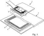
- FIG. 1 illustrates a ground pad 1 and a vehicle pad 2, both of which comprise an induction coil 3, 4.
- Wireless charging of a traction battery of an electric vehicle is realized by means of electromagnetic resonance between these induction coils, wherein the induction coil 3 of the ground pad 1 serves as a transmitting coil and the induction coil 4 of the vehicle pad 2 serves as a receiving coil.
- the coils 3, 4 are made of Litz wires which are wound around a substantially vertical axis, e.g. in a square shape.
- Each of the induction coil 3, 4 is surrounded by a ferrite shield 5, 6 for decreasing the influence of stray or secondary fields on the induction of stray metallic objects, as described before.
- the ferrite shields 5, 6 are for example made of iron containing ceramic.
- the ferrite shields 5, 6 could also be made of different magnetic oxides such as chrome oxide, ruthenium oxide, or other magnetically permeable oxides.
- the ferrite shields 5, 6 extend in a closed loop around the radial outer side of the induction coils 3, 4.
- the ferrite shields 3, 4 are electric field suppressors by contained microfields contained within the ceramic. Since these microfields involve the flipping of charges from the ferromagentic ceramic, the ceramic goes through a heating process during field suppression.
- heat transfer means 7 are attached to the ferrite shield 6 of the vehicle pad 2. This attachment can be realized in particular by welding or soldering.
- Fig. 2 schematically illustrates the heating device according to an example not covered by the invention.
- the Figure schematically shows the elements described with reference to Fig. 1 , namely the induction coils 3, 4 of the ground pad 1 and the vehicle pad 2, which are surrounded by the ferrite shields 5, 6.
- an encapsulant 8 is provided which is a cover for covering a side of the induction coil 4 facing towards the ground pad 1.
- the ground pad 1 has an encapsulant 9 which is a cover for covering a side of the induction coil 3 facing towards the vehicle pad 2.
- the encapsulants 8 and 9 are for example made of a plastic material.
- the heat transfer means 7 is a non-magnetic thermally conductive material which is attached to the ferrite shield 6 of the vehicle pad 2 and continuously extends to a traction battery 10, where it is attached to the traction battery 10, such that it covers at least 10% of an outer surface of the traction battery.
- the non-magnetic thermally conductive material covers at least one side of the traction battery 10.
- the non-magnetic thermally conductive material covers at least 20% of the outer surface of the traction battery.
- the non-magnetic thermally conductive material covers at least 50% of the outer surface of the traction battery.
- the non-magnetic thermally conductive material surrounds the entire outer surface of the traction battery on every side of it.
- the non-magnetic thermally conductive material is preferably a metallic nonmagnetic material comprising at least one of the following: tin, bronze, aluminum, carbon, zinc, lead, titanium, gold, silver, platinum.
- the non-magnetic thermally conductive material is made of at least one of the just mentioned materials or is made of one of the just mentioned materials. Also silicon-nitride coated copper would be a suitable material.
- the heat transfer means 11 is a heating circuit adapted to transfer heat from the ferrite shield to the traction battery by means of a circulated fluid.
- the heating circuit On one side, the heating circuit is attached to the ferrite shield 6, and on the other side, the heating circuit is attached to the traction battery 10.
- the heating circuit preferably contains a pump (not shown) for circulating the fluid in the heating circuit.
- the heating circuit is attached to the traction battery and covers at least 10% of an outer surface of the traction battery, for example by means of a heat exchanger.
- the heat transfer means 11 could also cover at least 50% of the outer surface of the traction battery, when being guided around the surface of the traction battery.
Landscapes
- Engineering & Computer Science (AREA)
- Power Engineering (AREA)
- Transportation (AREA)
- Mechanical Engineering (AREA)
- Life Sciences & Earth Sciences (AREA)
- Sustainable Development (AREA)
- Sustainable Energy (AREA)
- Electric Propulsion And Braking For Vehicles (AREA)
- Secondary Cells (AREA)
Description
- The present invention relates to a heating device for a traction battery of a vehicle, and a vehicle having such a heating device.
- During the wireless charging of the traction battery, the battery requires a thermal management, in order to maintain the battery within a temperature range which is suitable for the battery to be charged efficiently. The current state of the art is to utilize an external heating element (resistive filament) in order to heat the battery while being wirelessly charged. The power of the resistive filament is siphoned from the power to charge the battery, and thus the charging power is reduced while the battery is being pre-heated.
-
WO 2012/031721 A2 describes a heating device for a traction battery of a vehicle, comprising an induction coil for wireless charging of the traction battery, and heat transfer means for transferring heat from the induction coil to the traction battery for heating the traction battery, wherein the heat transfer means cover at least 10% of the outer surface of the traction battery, wherein the heat transfer means is a heating circuit adapted to transfer heat from the induction coil to the traction battery by means of a circulated fluid.US 2015/0197155 A1 discloses in Fig. 5A a multi-turn coil which is embedded in ferrite material which upper side is provided with a conductive layer. A battery space is surrounding the ferrite material.US 2015/0061593 A1 discloses an inductive coil being surrounded by ferrite material. - The object of the invention is to provide a heating device having improved energy efficiency.
- This object is achieved with a device according to the
claim 1. Advantageous further developments are subject of the dependent claims. - According to an embodiment of the invention a heating device for a traction battery of a vehicle is provided. The heating device comprises an induction coil for wireless charging of the traction battery; a ferrite shield surrounding the induction coil, and heat transfer means being a heating circuit adapted to transfer heat from the ferrite shield to the traction battery by means of a circulated fluid, the heat transfer means further being attached to the ferrite shield and being adapted to cover at least 10% of the outer surface of the traction battery.
- Wireless charging of a traction battery of an electric vehicle occurs through the electromagnetic resonance between two induction coils, a transmitting coil (ground pad), and a receiving coil (vehicle pad). The electromagnetic resonance works primarily through impedance matching between the two induction coils in wireless power transference. The impedance between the two coils is influenced by any magnetic or conductive material that may be within or near the transference environment, thus to decrease the influence of stray or secondary fields on the induction of stray metallic objects, the ferrite shield (i.e. an iron containing ceramic) is implemented around the transmitting and receiving coil. The ferrite shields are used to suppress any external heating outside of the wireless power transmission area. These ferrite shields are electric field suppressors by contained microfields contained within the ceramic. Since these microfields involve the flipping of charges from the ferromagentic ceramic, the ceramic goes through a heating process during field suppression. The above mentioned embodiment provides the benefit that some of this heat is drained off transferred through the heat transfer means to the traction battery and used for heating the traction battery. This on the other hand lowers the energy demand for heating the traction battery during charging and provides a better low temperature battery performance. The amount of heating that needs to be completed by a resistive filament is reduced allowing for more power to be diverted to battery charging while still maintaining heating through taking heat from the ferrite shield.
- According to an example not covered by the invention the heat transfer means is a thermally conductive material.
- According to an example not covered by the invention the heat transfer means is a non-magnetic thermally conductive material.
- According to an example not covered by the invention the thermally conductive material comprises at least one of the following: tin, bronze, aluminum, carbon.
- According to an example not covered by the invention the thermally conductive material encapsulates at least 50% of the outer surface of the traction battery.
- Further, the invention provides a vehicle comprising a traction battery and a heating device according to the preceding embodiment.
- Other objects, advantages and novel features of the present invention will become apparent from the following detailed description of one or more preferred embodiments when considered in conjunction with the accompanying drawings.
-
-
Fig. 1 illustrates a ground pad and a vehicle pad for wireless charging; -
Fig. 2 schematically illustrates the heating device according an example not covered by the invention and -
Fig. 3 schematically illustrates the heating device according to an embodiment of the invention. -
Figure 1 illustrates aground pad 1 and avehicle pad 2, both of which comprise aninduction coil induction coil 3 of theground pad 1 serves as a transmitting coil and theinduction coil 4 of thevehicle pad 2 serves as a receiving coil. Thecoils induction coil ferrite shield ferrite shields ferrite shields ferrite shields induction coils ferrite shields ferrite shield 6 of thevehicle pad 2. This attachment can be realized in particular by welding or soldering. -
Fig. 2 schematically illustrates the heating device according to an example not covered by the invention. The Figure schematically shows the elements described with reference toFig. 1 , namely theinduction coils ground pad 1 and thevehicle pad 2, which are surrounded by theferrite shields encapsulant 8 is provided which is a cover for covering a side of theinduction coil 4 facing towards theground pad 1. Similarly, theground pad 1 has an encapsulant 9 which is a cover for covering a side of theinduction coil 3 facing towards thevehicle pad 2. Theencapsulants - In this example the heat transfer means 7 is a non-magnetic thermally conductive material which is attached to the
ferrite shield 6 of thevehicle pad 2 and continuously extends to atraction battery 10, where it is attached to thetraction battery 10, such that it covers at least 10% of an outer surface of the traction battery. In particular, the non-magnetic thermally conductive material covers at least one side of thetraction battery 10. In particular, the non-magnetic thermally conductive material covers at least 20% of the outer surface of the traction battery. In particular, the non-magnetic thermally conductive material covers at least 50% of the outer surface of the traction battery. In particular, the non-magnetic thermally conductive material surrounds the entire outer surface of the traction battery on every side of it. - The non-magnetic thermally conductive material is preferably a metallic nonmagnetic material comprising at least one of the following: tin, bronze, aluminum, carbon, zinc, lead, titanium, gold, silver, platinum. In particular, the non-magnetic thermally conductive material is made of at least one of the just mentioned materials or is made of one of the just mentioned materials. Also silicon-nitride coated copper would be a suitable material.
-
Fig. 3 schematically illustrates the heating device according to an embodiment of the invention. With respect to elements having the same reference numeral than those inFigs. 1 and2 , it is referred to the above description in connection with these Figures.
In this embodiment, the heat transfer means 11 is a heating circuit adapted to transfer heat from the ferrite shield to the traction battery by means of a circulated fluid. On one side, the heating circuit is attached to theferrite shield 6, and on the other side, the heating circuit is attached to thetraction battery 10. The heating circuit preferably contains a pump (not shown) for circulating the fluid in the heating circuit. The heating circuit is attached to the traction battery and covers at least 10% of an outer surface of the traction battery, for example by means of a heat exchanger. The heat transfer means 11 could also cover at least 50% of the outer surface of the traction battery, when being guided around the surface of the traction battery. - The foregoing disclosure has been set forth merely to illustrate the invention and is not intended to be limiting. Since modifications of the disclosed embodiments may occur to persons skilled in the art, the invention should be construed to include everything within the scope of the appended claims and equivalents thereof.
Claims (2)
- Heating device for a traction battery (10) of a vehicle, comprising:an induction coil (4) for wireless charging of the traction battery (10);a ferrite shield (6) surrounding the induction coil (4), andheat transfer means (11) being a heating circuit adapted to transfer heat from the ferrite shield (6) to the traction battery (10) by means of a circulated fluid, the heat transfer means (11) further being attached to the ferrite shield (6) and being adapted to cover at least 10% of the outer surface of the traction battery (10).
- Vehicle comprising a traction battery (10) and a heating device according to claim 1.
Priority Applications (1)
| Application Number | Priority Date | Filing Date | Title |
|---|---|---|---|
| EP17205873.7A EP3495191B1 (en) | 2017-12-07 | 2017-12-07 | Heating device for a traction battery of a vehicle, and vehicle having the same |
Applications Claiming Priority (1)
| Application Number | Priority Date | Filing Date | Title |
|---|---|---|---|
| EP17205873.7A EP3495191B1 (en) | 2017-12-07 | 2017-12-07 | Heating device for a traction battery of a vehicle, and vehicle having the same |
Publications (2)
| Publication Number | Publication Date |
|---|---|
| EP3495191A1 EP3495191A1 (en) | 2019-06-12 |
| EP3495191B1 true EP3495191B1 (en) | 2021-03-03 |
Family
ID=60654723
Family Applications (1)
| Application Number | Title | Priority Date | Filing Date |
|---|---|---|---|
| EP17205873.7A Active EP3495191B1 (en) | 2017-12-07 | 2017-12-07 | Heating device for a traction battery of a vehicle, and vehicle having the same |
Country Status (1)
| Country | Link |
|---|---|
| EP (1) | EP3495191B1 (en) |
Citations (2)
| Publication number | Priority date | Publication date | Assignee | Title |
|---|---|---|---|---|
| US20150061593A1 (en) * | 2012-04-17 | 2015-03-05 | Conductix-Wampfler Gmbh | Coil unit and electric vehicle |
| US20150197155A1 (en) * | 2014-01-10 | 2015-07-16 | Qualcomm Incorporated | Controlling current flow path in wireless electric vehicle charging systems for mitigating rf radiated emissions |
Family Cites Families (4)
| Publication number | Priority date | Publication date | Assignee | Title |
|---|---|---|---|---|
| GB1544455A (en) * | 1975-06-03 | 1979-04-19 | Miyahara H | Secondary battery charger |
| DE102010044999A1 (en) * | 2010-09-10 | 2012-03-15 | Li-Tec Battery Gmbh | Arrangement and method for charging a vehicle battery |
| JP2012204259A (en) * | 2011-03-28 | 2012-10-22 | Voc Direct:Kk | Battery heat insulation method for automatic guided vehicle under low-temperature environment |
| US9878703B2 (en) * | 2016-03-08 | 2018-01-30 | Ford Global Technologies, Llc | Electrified vehicle with power dissipation feature |
-
2017
- 2017-12-07 EP EP17205873.7A patent/EP3495191B1/en active Active
Patent Citations (2)
| Publication number | Priority date | Publication date | Assignee | Title |
|---|---|---|---|---|
| US20150061593A1 (en) * | 2012-04-17 | 2015-03-05 | Conductix-Wampfler Gmbh | Coil unit and electric vehicle |
| US20150197155A1 (en) * | 2014-01-10 | 2015-07-16 | Qualcomm Incorporated | Controlling current flow path in wireless electric vehicle charging systems for mitigating rf radiated emissions |
Also Published As
| Publication number | Publication date |
|---|---|
| EP3495191A1 (en) | 2019-06-12 |
Similar Documents
| Publication | Publication Date | Title |
|---|---|---|
| US20230327491A1 (en) | Transmitting assembly for a universal wireless charging device and a method thereof | |
| EP3432328B1 (en) | Coil apparatus | |
| CN115088196B (en) | Systems and methods for wireless power and data transmission utilizing multiple antenna receivers | |
| EP3123486B1 (en) | Temperature management for inductive charging systems | |
| US11528058B2 (en) | Inductive charging coil configuration for wearable electronic devices | |
| US9859718B2 (en) | Power supply unit, power receiving unit, and power supply system | |
| EP2576274B1 (en) | A wireless power receiving unit, a wireless power transferring unit, a wireless power transferring device and use of a wireless power transferring device | |
| WO2013107920A1 (en) | Method and shielding units for inductive energy coils | |
| US9973023B2 (en) | Inductive energy transfer coil structure | |
| KR101971091B1 (en) | Antenna module includeing sheilding layer and wireless power receiving apparatus | |
| US20150348696A1 (en) | Induction charging coil device | |
| CN108199493A (en) | A kind of electromagnetic screen, wireless charging transmitting terminal, receiving terminal and system | |
| CN115210988A (en) | Wireless power transmission system using multiple transmitting antennas and common electronic device | |
| TW201941517A (en) | Wireless power transmitter / receiver device | |
| US10320221B2 (en) | Wireless power charging system | |
| CN109167443A (en) | Wireless charging attachment device, wireless charging transmitting terminal, receiving end and system | |
| EP2953148B1 (en) | Contactless-power-transfer-device coil and contactless power-transfer device | |
| JP6061067B2 (en) | Contactless power receiving device | |
| WO2014147730A1 (en) | Package structure | |
| JP6148501B2 (en) | Power transmission system | |
| EP3495191B1 (en) | Heating device for a traction battery of a vehicle, and vehicle having the same | |
| US20250183716A1 (en) | High efficiency wireless power transfer to implantable devices | |
| EP2996220B1 (en) | Wireless power reception device | |
| US10304621B2 (en) | Bobbin with electromagnetic interference shield for electromagnetic device | |
| KR101823206B1 (en) | Sheet for shielding electromagnetic wave and wireless power charging device |
Legal Events
| Date | Code | Title | Description |
|---|---|---|---|
| PUAI | Public reference made under article 153(3) epc to a published international application that has entered the european phase |
Free format text: ORIGINAL CODE: 0009012 |
|
| STAA | Information on the status of an ep patent application or granted ep patent |
Free format text: STATUS: EXAMINATION IS IN PROGRESS |
|
| 17P | Request for examination filed |
Effective date: 20180712 |
|
| AK | Designated contracting states |
Kind code of ref document: A1 Designated state(s): AL AT BE BG CH CY CZ DE DK EE ES FI FR GB GR HR HU IE IS IT LI LT LU LV MC MK MT NL NO PL PT RO RS SE SI SK SM TR |
|
| AX | Request for extension of the european patent |
Extension state: BA ME |
|
| REG | Reference to a national code |
Ref country code: DE Ref legal event code: R079 Ref document number: 602017033719 Country of ref document: DE Free format text: PREVIOUS MAIN CLASS: B60L0011180000 Ipc: B60L0053120000 |
|
| GRAP | Despatch of communication of intention to grant a patent |
Free format text: ORIGINAL CODE: EPIDOSNIGR1 |
|
| STAA | Information on the status of an ep patent application or granted ep patent |
Free format text: STATUS: GRANT OF PATENT IS INTENDED |
|
| RIC1 | Information provided on ipc code assigned before grant |
Ipc: B60L 58/27 20190101ALI20201023BHEP Ipc: B60L 53/12 20190101AFI20201023BHEP |
|
| INTG | Intention to grant announced |
Effective date: 20201120 |
|
| GRAS | Grant fee paid |
Free format text: ORIGINAL CODE: EPIDOSNIGR3 |
|
| GRAA | (expected) grant |
Free format text: ORIGINAL CODE: 0009210 |
|
| STAA | Information on the status of an ep patent application or granted ep patent |
Free format text: STATUS: THE PATENT HAS BEEN GRANTED |
|
| AK | Designated contracting states |
Kind code of ref document: B1 Designated state(s): AL AT BE BG CH CY CZ DE DK EE ES FI FR GB GR HR HU IE IS IT LI LT LU LV MC MK MT NL NO PL PT RO RS SE SI SK SM TR |
|
| REG | Reference to a national code |
Ref country code: GB Ref legal event code: FG4D |
|
| REG | Reference to a national code |
Ref country code: AT Ref legal event code: REF Ref document number: 1366847 Country of ref document: AT Kind code of ref document: T Effective date: 20210315 Ref country code: CH Ref legal event code: EP |
|
| REG | Reference to a national code |
Ref country code: DE Ref legal event code: R096 Ref document number: 602017033719 Country of ref document: DE |
|
| REG | Reference to a national code |
Ref country code: IE Ref legal event code: FG4D |
|
| REG | Reference to a national code |
Ref country code: LT Ref legal event code: MG9D |
|
| PG25 | Lapsed in a contracting state [announced via postgrant information from national office to epo] |
Ref country code: NO Free format text: LAPSE BECAUSE OF FAILURE TO SUBMIT A TRANSLATION OF THE DESCRIPTION OR TO PAY THE FEE WITHIN THE PRESCRIBED TIME-LIMIT Effective date: 20210603 Ref country code: HR Free format text: LAPSE BECAUSE OF FAILURE TO SUBMIT A TRANSLATION OF THE DESCRIPTION OR TO PAY THE FEE WITHIN THE PRESCRIBED TIME-LIMIT Effective date: 20210303 Ref country code: GR Free format text: LAPSE BECAUSE OF FAILURE TO SUBMIT A TRANSLATION OF THE DESCRIPTION OR TO PAY THE FEE WITHIN THE PRESCRIBED TIME-LIMIT Effective date: 20210604 Ref country code: FI Free format text: LAPSE BECAUSE OF FAILURE TO SUBMIT A TRANSLATION OF THE DESCRIPTION OR TO PAY THE FEE WITHIN THE PRESCRIBED TIME-LIMIT Effective date: 20210303 Ref country code: BG Free format text: LAPSE BECAUSE OF FAILURE TO SUBMIT A TRANSLATION OF THE DESCRIPTION OR TO PAY THE FEE WITHIN THE PRESCRIBED TIME-LIMIT Effective date: 20210603 Ref country code: LT Free format text: LAPSE BECAUSE OF FAILURE TO SUBMIT A TRANSLATION OF THE DESCRIPTION OR TO PAY THE FEE WITHIN THE PRESCRIBED TIME-LIMIT Effective date: 20210303 |
|
| REG | Reference to a national code |
Ref country code: NL Ref legal event code: MP Effective date: 20210303 |
|
| REG | Reference to a national code |
Ref country code: AT Ref legal event code: MK05 Ref document number: 1366847 Country of ref document: AT Kind code of ref document: T Effective date: 20210303 |
|
| PG25 | Lapsed in a contracting state [announced via postgrant information from national office to epo] |
Ref country code: SE Free format text: LAPSE BECAUSE OF FAILURE TO SUBMIT A TRANSLATION OF THE DESCRIPTION OR TO PAY THE FEE WITHIN THE PRESCRIBED TIME-LIMIT Effective date: 20210303 Ref country code: RS Free format text: LAPSE BECAUSE OF FAILURE TO SUBMIT A TRANSLATION OF THE DESCRIPTION OR TO PAY THE FEE WITHIN THE PRESCRIBED TIME-LIMIT Effective date: 20210303 Ref country code: PL Free format text: LAPSE BECAUSE OF FAILURE TO SUBMIT A TRANSLATION OF THE DESCRIPTION OR TO PAY THE FEE WITHIN THE PRESCRIBED TIME-LIMIT Effective date: 20210303 Ref country code: LV Free format text: LAPSE BECAUSE OF FAILURE TO SUBMIT A TRANSLATION OF THE DESCRIPTION OR TO PAY THE FEE WITHIN THE PRESCRIBED TIME-LIMIT Effective date: 20210303 |
|
| PG25 | Lapsed in a contracting state [announced via postgrant information from national office to epo] |
Ref country code: NL Free format text: LAPSE BECAUSE OF FAILURE TO SUBMIT A TRANSLATION OF THE DESCRIPTION OR TO PAY THE FEE WITHIN THE PRESCRIBED TIME-LIMIT Effective date: 20210303 |
|
| PG25 | Lapsed in a contracting state [announced via postgrant information from national office to epo] |
Ref country code: EE Free format text: LAPSE BECAUSE OF FAILURE TO SUBMIT A TRANSLATION OF THE DESCRIPTION OR TO PAY THE FEE WITHIN THE PRESCRIBED TIME-LIMIT Effective date: 20210303 Ref country code: CZ Free format text: LAPSE BECAUSE OF FAILURE TO SUBMIT A TRANSLATION OF THE DESCRIPTION OR TO PAY THE FEE WITHIN THE PRESCRIBED TIME-LIMIT Effective date: 20210303 Ref country code: AT Free format text: LAPSE BECAUSE OF FAILURE TO SUBMIT A TRANSLATION OF THE DESCRIPTION OR TO PAY THE FEE WITHIN THE PRESCRIBED TIME-LIMIT Effective date: 20210303 Ref country code: SM Free format text: LAPSE BECAUSE OF FAILURE TO SUBMIT A TRANSLATION OF THE DESCRIPTION OR TO PAY THE FEE WITHIN THE PRESCRIBED TIME-LIMIT Effective date: 20210303 |
|
| PG25 | Lapsed in a contracting state [announced via postgrant information from national office to epo] |
Ref country code: SK Free format text: LAPSE BECAUSE OF FAILURE TO SUBMIT A TRANSLATION OF THE DESCRIPTION OR TO PAY THE FEE WITHIN THE PRESCRIBED TIME-LIMIT Effective date: 20210303 Ref country code: RO Free format text: LAPSE BECAUSE OF FAILURE TO SUBMIT A TRANSLATION OF THE DESCRIPTION OR TO PAY THE FEE WITHIN THE PRESCRIBED TIME-LIMIT Effective date: 20210303 Ref country code: PT Free format text: LAPSE BECAUSE OF FAILURE TO SUBMIT A TRANSLATION OF THE DESCRIPTION OR TO PAY THE FEE WITHIN THE PRESCRIBED TIME-LIMIT Effective date: 20210705 Ref country code: IS Free format text: LAPSE BECAUSE OF FAILURE TO SUBMIT A TRANSLATION OF THE DESCRIPTION OR TO PAY THE FEE WITHIN THE PRESCRIBED TIME-LIMIT Effective date: 20210703 |
|
| REG | Reference to a national code |
Ref country code: DE Ref legal event code: R097 Ref document number: 602017033719 Country of ref document: DE |
|
| PLBE | No opposition filed within time limit |
Free format text: ORIGINAL CODE: 0009261 |
|
| STAA | Information on the status of an ep patent application or granted ep patent |
Free format text: STATUS: NO OPPOSITION FILED WITHIN TIME LIMIT |
|
| PG25 | Lapsed in a contracting state [announced via postgrant information from national office to epo] |
Ref country code: AL Free format text: LAPSE BECAUSE OF FAILURE TO SUBMIT A TRANSLATION OF THE DESCRIPTION OR TO PAY THE FEE WITHIN THE PRESCRIBED TIME-LIMIT Effective date: 20210303 Ref country code: DK Free format text: LAPSE BECAUSE OF FAILURE TO SUBMIT A TRANSLATION OF THE DESCRIPTION OR TO PAY THE FEE WITHIN THE PRESCRIBED TIME-LIMIT Effective date: 20210303 Ref country code: ES Free format text: LAPSE BECAUSE OF FAILURE TO SUBMIT A TRANSLATION OF THE DESCRIPTION OR TO PAY THE FEE WITHIN THE PRESCRIBED TIME-LIMIT Effective date: 20210303 |
|
| 26N | No opposition filed |
Effective date: 20211206 |
|
| PG25 | Lapsed in a contracting state [announced via postgrant information from national office to epo] |
Ref country code: SI Free format text: LAPSE BECAUSE OF FAILURE TO SUBMIT A TRANSLATION OF THE DESCRIPTION OR TO PAY THE FEE WITHIN THE PRESCRIBED TIME-LIMIT Effective date: 20210303 |
|
| PG25 | Lapsed in a contracting state [announced via postgrant information from national office to epo] |
Ref country code: IT Free format text: LAPSE BECAUSE OF FAILURE TO SUBMIT A TRANSLATION OF THE DESCRIPTION OR TO PAY THE FEE WITHIN THE PRESCRIBED TIME-LIMIT Effective date: 20210303 |
|
| PG25 | Lapsed in a contracting state [announced via postgrant information from national office to epo] |
Ref country code: IS Free format text: LAPSE BECAUSE OF FAILURE TO SUBMIT A TRANSLATION OF THE DESCRIPTION OR TO PAY THE FEE WITHIN THE PRESCRIBED TIME-LIMIT Effective date: 20210703 |
|
| PG25 | Lapsed in a contracting state [announced via postgrant information from national office to epo] |
Ref country code: MC Free format text: LAPSE BECAUSE OF FAILURE TO SUBMIT A TRANSLATION OF THE DESCRIPTION OR TO PAY THE FEE WITHIN THE PRESCRIBED TIME-LIMIT Effective date: 20210303 |
|
| REG | Reference to a national code |
Ref country code: CH Ref legal event code: PL |
|
| REG | Reference to a national code |
Ref country code: BE Ref legal event code: MM Effective date: 20211231 |
|
| PG25 | Lapsed in a contracting state [announced via postgrant information from national office to epo] |
Ref country code: LU Free format text: LAPSE BECAUSE OF NON-PAYMENT OF DUE FEES Effective date: 20211207 Ref country code: IE Free format text: LAPSE BECAUSE OF NON-PAYMENT OF DUE FEES Effective date: 20211207 |
|
| PG25 | Lapsed in a contracting state [announced via postgrant information from national office to epo] |
Ref country code: BE Free format text: LAPSE BECAUSE OF NON-PAYMENT OF DUE FEES Effective date: 20211231 |
|
| PG25 | Lapsed in a contracting state [announced via postgrant information from national office to epo] |
Ref country code: LI Free format text: LAPSE BECAUSE OF NON-PAYMENT OF DUE FEES Effective date: 20211231 Ref country code: CH Free format text: LAPSE BECAUSE OF NON-PAYMENT OF DUE FEES Effective date: 20211231 |
|
| P01 | Opt-out of the competence of the unified patent court (upc) registered |
Effective date: 20230503 |
|
| PG25 | Lapsed in a contracting state [announced via postgrant information from national office to epo] |
Ref country code: CY Free format text: LAPSE BECAUSE OF FAILURE TO SUBMIT A TRANSLATION OF THE DESCRIPTION OR TO PAY THE FEE WITHIN THE PRESCRIBED TIME-LIMIT Effective date: 20210303 |
|
| PG25 | Lapsed in a contracting state [announced via postgrant information from national office to epo] |
Ref country code: HU Free format text: LAPSE BECAUSE OF FAILURE TO SUBMIT A TRANSLATION OF THE DESCRIPTION OR TO PAY THE FEE WITHIN THE PRESCRIBED TIME-LIMIT; INVALID AB INITIO Effective date: 20171207 |
|
| PG25 | Lapsed in a contracting state [announced via postgrant information from national office to epo] |
Ref country code: MK Free format text: LAPSE BECAUSE OF FAILURE TO SUBMIT A TRANSLATION OF THE DESCRIPTION OR TO PAY THE FEE WITHIN THE PRESCRIBED TIME-LIMIT Effective date: 20210303 |
|
| PG25 | Lapsed in a contracting state [announced via postgrant information from national office to epo] |
Ref country code: TR Free format text: LAPSE BECAUSE OF FAILURE TO SUBMIT A TRANSLATION OF THE DESCRIPTION OR TO PAY THE FEE WITHIN THE PRESCRIBED TIME-LIMIT Effective date: 20210303 |
|
| PG25 | Lapsed in a contracting state [announced via postgrant information from national office to epo] |
Ref country code: MT Free format text: LAPSE BECAUSE OF FAILURE TO SUBMIT A TRANSLATION OF THE DESCRIPTION OR TO PAY THE FEE WITHIN THE PRESCRIBED TIME-LIMIT Effective date: 20210303 |
|
| PGFP | Annual fee paid to national office [announced via postgrant information from national office to epo] |
Ref country code: DE Payment date: 20251203 Year of fee payment: 9 |
|
| PGFP | Annual fee paid to national office [announced via postgrant information from national office to epo] |
Ref country code: GB Payment date: 20251218 Year of fee payment: 9 |
|
| PGFP | Annual fee paid to national office [announced via postgrant information from national office to epo] |
Ref country code: FR Payment date: 20251217 Year of fee payment: 9 |