EP3495152A1 - Printer - Google Patents
Printer Download PDFInfo
- Publication number
- EP3495152A1 EP3495152A1 EP18210935.5A EP18210935A EP3495152A1 EP 3495152 A1 EP3495152 A1 EP 3495152A1 EP 18210935 A EP18210935 A EP 18210935A EP 3495152 A1 EP3495152 A1 EP 3495152A1
- Authority
- EP
- European Patent Office
- Prior art keywords
- display unit
- printer
- mounting surface
- housing
- pair
- Prior art date
- Legal status (The legal status is an assumption and is not a legal conclusion. Google has not performed a legal analysis and makes no representation as to the accuracy of the status listed.)
- Granted
Links
Images




Classifications
-
- B—PERFORMING OPERATIONS; TRANSPORTING
- B41—PRINTING; LINING MACHINES; TYPEWRITERS; STAMPS
- B41J—TYPEWRITERS; SELECTIVE PRINTING MECHANISMS, i.e. MECHANISMS PRINTING OTHERWISE THAN FROM A FORME; CORRECTION OF TYPOGRAPHICAL ERRORS
- B41J29/00—Details of, or accessories for, typewriters or selective printing mechanisms not otherwise provided for
- B41J29/02—Framework
-
- B—PERFORMING OPERATIONS; TRANSPORTING
- B41—PRINTING; LINING MACHINES; TYPEWRITERS; STAMPS
- B41J—TYPEWRITERS; SELECTIVE PRINTING MECHANISMS, i.e. MECHANISMS PRINTING OTHERWISE THAN FROM A FORME; CORRECTION OF TYPOGRAPHICAL ERRORS
- B41J2/00—Typewriters or selective printing mechanisms characterised by the printing or marking process for which they are designed
- B41J2/315—Typewriters or selective printing mechanisms characterised by the printing or marking process for which they are designed characterised by selective application of heat to a heat sensitive printing or impression-transfer material
- B41J2/32—Typewriters or selective printing mechanisms characterised by the printing or marking process for which they are designed characterised by selective application of heat to a heat sensitive printing or impression-transfer material using thermal heads
-
- B—PERFORMING OPERATIONS; TRANSPORTING
- B41—PRINTING; LINING MACHINES; TYPEWRITERS; STAMPS
- B41J—TYPEWRITERS; SELECTIVE PRINTING MECHANISMS, i.e. MECHANISMS PRINTING OTHERWISE THAN FROM A FORME; CORRECTION OF TYPOGRAPHICAL ERRORS
- B41J29/00—Details of, or accessories for, typewriters or selective printing mechanisms not otherwise provided for
- B41J29/12—Guards, shields or dust excluders
- B41J29/13—Cases or covers
-
- B—PERFORMING OPERATIONS; TRANSPORTING
- B41—PRINTING; LINING MACHINES; TYPEWRITERS; STAMPS
- B41J—TYPEWRITERS; SELECTIVE PRINTING MECHANISMS, i.e. MECHANISMS PRINTING OTHERWISE THAN FROM A FORME; CORRECTION OF TYPOGRAPHICAL ERRORS
- B41J3/00—Typewriters or selective printing or marking mechanisms characterised by the purpose for which they are constructed
- B41J3/44—Typewriters or selective printing mechanisms having dual functions or combined with, or coupled to, apparatus performing other functions
- B41J3/46—Printing mechanisms combined with apparatus providing a visual indication
-
- H—ELECTRICITY
- H04—ELECTRIC COMMUNICATION TECHNIQUE
- H04N—PICTORIAL COMMUNICATION, e.g. TELEVISION
- H04N1/00—Scanning, transmission or reproduction of documents or the like, e.g. facsimile transmission; Details thereof
- H04N1/00127—Connection or combination of a still picture apparatus with another apparatus, e.g. for storage, processing or transmission of still picture signals or of information associated with a still picture
- H04N1/00129—Connection or combination of a still picture apparatus with another apparatus, e.g. for storage, processing or transmission of still picture signals or of information associated with a still picture with a display device, e.g. CRT or LCD monitor
-
- H—ELECTRICITY
- H04—ELECTRIC COMMUNICATION TECHNIQUE
- H04N—PICTORIAL COMMUNICATION, e.g. TELEVISION
- H04N1/00—Scanning, transmission or reproduction of documents or the like, e.g. facsimile transmission; Details thereof
- H04N1/00519—Constructional details not otherwise provided for, e.g. housings, covers
- H04N1/00538—Modular devices, i.e. allowing combinations of separate components, removal or replacement of components
Definitions
- the present invention relates to a printer.
- a printer which is to be used for a point-of-sale system (POS), and includes a display unit configured to display predetermined information and a printer main body portion connected to the display unit through a cable.
- the display unit is arranged on a printer stand configured to support the printer main body portion.
- a printer including: a housing, which has a recording paper receiving portion having an opening, and includes a plurality of outer surfaces including a bottom surface to be opposed to an installation surface; a printer cover, which is coupled to the housing, and is capable of opening and closing the opening; a display unit, which is removably mounted on a mounting surface other than the bottom surface among the plurality of outer surfaces, and is configured to display predetermined information; a cable having one end connected to the display unit and another end on which a connector is mounted; and a connector connecting portion to which the connector is connected.
- the housing has a box shape, wherein the opening is formed on a side, and wherein the mounting surface comprises a side surface on a side opposite to the opening among the plurality of outer surfaces.
- the display unit includes a display region on which the predetermined information is displayed, and wherein the display region has a size set to a region corresponding to the mounting surface.
- a recessed portion that is recessed inward from the mounting surface is formed in the lower part of the mounting surface, and wherein the connector connecting portion is formed in the recessed portion.
- the mounting surface has both edge portions in which a pair of elastically deformable sandwiching portions are formed, and wherein the display unit is mounted on the mounting surface so as to be sandwiched by the pair of elastically deformable sandwiching portions.
- a pair of grooves are formed so as to be opposed to each other along the both sides, and wherein the display unit is mounted on the mounting surface through insertion of both sides of the display unit into the pair of grooves.
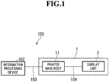
- FIG. 1 is a block diagram of a point-of-sale system (POS) including a thermal printer according to the first embodiment.
- POS point-of-sale system
- a POS 101 is installed in commercial places such as retail stores and restaurants.
- the POS 101 is a system configured to notify customers of payment information (predetermined information) such as names and prices of products purchased by the customers.
- the POS 101 includes an information processing device 102 and a thermal printer 1 (corresponding to the "printer" in claims).
- the information processing device 102 is configured to perform, for example, payment processing for the products.
- the information processing device 102 is configured to control the operation of the thermal printer 1.
- the information processing device 102 there are given personal computers of a desktop type and a tablet type.
- the thermal printer 1 is installed on a store counter.
- the thermal printer 1 includes a printer main body 11 and a display unit 7.
- the printer main body 11 and the information processing device 102 are connected to each other through a first cable 103, for example, a universal serial bus (USB) cable.
- the printer main body 11 and the information processing device 102 may be wirelessly connected to each other.
- the operation of the printer main body 11 is controlled by the information processing device 102.
- the printer main body 11 is configured to print data such as payment information sent from the information processing device 102 on recording paper P (see FIG. 2 ) such as heat-sensitive paper and deliver the printed recording paper P.
- the display unit 7 and the printer main body 11 are connected to each other through a second cable 104, for example, a USB cable. With this, the display unit 7 receives electric power supplied from the printer main body 11.
- the display unit 7 is connected to the information processing device 102 through intermediation of the printer main body 11. With this, the display unit 7 displays the data such as payment information sent from the information processing device 102.
- FIG. 2 is a perspective view of the thermal printer according to the first embodiment in a state in which a printer cover is closed.
- FIG. 3 is a perspective view of the thermal printer according to the first embodiment in a state in which the printer cover is opened.
- an upper side of the drawing sheet is defined as an upward direction (upward direction in a gravity direction)
- a lower side of the drawing sheet is defined as a downward direction (downward direction in the gravity direction).
- a front-and-back direction is denoted by L1.
- An up-and-down direction is denoted by L2.
- a direction orthogonal to the front-and-back direction L1 and the up-and-down direction L2 is defined as a right-and-left direction L3.
- a forward direction is indicated by the arrow FW
- a backward direction is indicated by the arrow BA.
- the thermal printer 1 is a printer of a "forward delivery" type in which the recording paper P is delivered in the forward direction (on a front surface 22 side of the thermal printer 1).
- the thermal printer 1 is used in a state in which the forward direction thereof is directed to, for example, a store clerk who is a first user, and the backward direction thereof is directed to, for example, a store customer who is a second user.
- This usage state of the thermal printer 1 is merely an example, and there is no particular limitation on the usage state.
- the printer main body 11 includes a housing 2 and a printer cover 3.
- the housing 2 is installed on an installation surface 110 in a store. As illustrated in FIG. 3 , the housing 2 has a box shape having an opening 25 in the forward direction.
- the housing 2 has a plurality of outer surfaces including a bottom surface 21, the front surface 22, and a back surface 23.
- the bottom surface 21 is formed, in a large part, so as to be opposed to the installation surface 110 in a state of being separated therefrom.
- the front surface 22 is formed of the printer cover 3 arranged in the opening 25.
- the back surface 23 forms a mounting surface 23A on which the display unit 7 (see FIG. 4 and FIG. 5 ) described later is removably mounted.
- the mounting surface 23A is positioned on a side opposite to the front surface 22.
- the printer cover 3 is coupled to a lower part of the housing 2 so as to open and close the opening 25 of the housing 2.
- a delivery slot 12 (gap) is formed between a distal end part of the printer cover 3 and the housing 2.
- the recording paper P is delivered in the forward direction from an inside of the housing 2 through the delivery slot 12.
- the recording paper receiving portion 10 is formed in the housing 2.
- the recording paper P is received in the recording paper receiving portion 10 in a state of being wound into a tubular shape having an axial line extending along the right-and-left direction L3.
- a platen unit 4 is provided on a back surface of the printer cover 3.
- the platen unit 4 is a component of the printer main body 11.
- the platen unit 4 is configured to send out the recording paper P in the forward direction from the delivery slot 12 (see FIG. 2 ).
- a head unit 5 is provided in the upward direction of the recording paper receiving portion 10 in the housing 2.
- the head unit 5 is a component of the printer main body 11.
- the head unit 5 is electrically connected to the information processing device 102 through the first cable 103.
- the head unit 5 is configured to print, on the recording paper P, data such as payment information sent from the information processing device 102.
- FIG. 4 is a perspective view of the thermal printer according to the first embodiment when viewed from the back surface side.
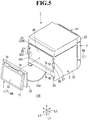
- FIG. 5 is an exploded perspective view of the thermal printer according to the first embodiment.
- the display unit 7 is removably mounted on the mounting surface 23A of the housing 2.
- the display unit 7 includes a display unit main body 71 and a display unit mounting portion 72.
- the display unit main body 71 has a plate shape.
- One end of the second cable 104 (see FIG. 5 ) is connected to the display unit main body 71.
- One end of the second cable 104 may be removably connected to the display unit main body 71, for example, through a connector (not shown).
- a display screen 73 (corresponding to the "display region" in the claims) is provided on the display unit main body 71. Data such as payment information sent from the information processing device 102 are displayed in forms of characters and images on the display screen 73.
- the size of the display screen 73 (size of the display region) is set to a region corresponding to the mounting surface 23A.
- the display unit mounting portion 72 has a plate shape.
- the display unit mounting portion 72 is mounted on the mounting surface 23A of the housing 2.
- An upper part of the display unit mounting portion 72 is pivotably mounted on an upper part of the display unit main body 71 through intermediation of pivot portions 74 formed of, for example, hinges. With the pivot portions 74, the display screen 73 of the display unit main body 71 can be changed in angle with respect to the mounting surface 23A.
- a display unit arrangement portion 26 is formed so as to be recessed in the mounting surface 23A of the housing 2.
- the display unit mounting portion 72 is arranged in the display unit arrangement portion 26. The movement of a lower part of the display unit mounting portion 72 is regulated by holding the lower part of the display unit mounting portion 72 in abutment against a step portion 29 on a lower side of the display unit arrangement portion 26.
- a pair of sandwiching portions 28 and 28 are arranged so as to be opposed to each other in edge portions 27 and 27 on the right and left sides of the display unit arrangement portion 26.
- the pair of sandwiching portions 28 and 28 are formed so as to be elastically deformable.
- the right and left sides of the display unit mounting portion 72 are sandwiched by the pair of sandwiching portions 28 and 28 through use of elastic force.
- the right and left sides of the display unit mounting portion 72 are sandwiched by the pair of sandwiching portions 28 and 28 through snap-fitting.
- the sandwiching portion 28 includes a base portion 281 and a locking claw 282.
- the base portion 281 is connected to the edge portion 27.
- the base portion 281 extends in the up-and-down direction L2 that is an extending direction of the edge portion 27 and protrudes in the backward direction.
- the locking claw 282 is formed at a distal end of the base portion 281.
- the locking claw 282 has a triangular shape in cross section.
- the display unit mounting portion 72 is locked on inner sides of the locking claws 282 and 282 with elastic force of the base portions 281.
- the display unit 7 can be mounted on and removed from the mounting surface 23A by elastically deforming the base portions 281 and 281 of the pair of sandwiching portions 28 and 28.
- FIG. 6 is a sectional view of the thermal printer taken along the line VI-VI of FIG. 5 .
- a recessed portion 82 is formed in a lower part of the mounting surface 23A.
- the recessed portion 82 is formed so as to be recessed inward from the mounting surface 23A (toward an inner side of the housing 2).
- the recessed portion 82 has an L-shape in side sectional view.
- a connector connecting portion 81 is formed in the recessed portion 82.
- the connector connecting portion 81 is formed on a side surface 83 facing the front-and-back direction L1 in the recessed portion 82.
- a connector 105 mounted on the second cable 104 is connected to the connector connecting portion 81 so as to be mountable on and removable from the connector connecting portion 81 through insertion and removal of the connector 105 along the front-and-back direction L1.
- a locking portion capable of accommodating the second cable 104 by locking the second cable 104 may be formed in the recessed portion 82.
- the display unit 7 is removably mounted on the mounting surface 23A of the housing 2 other than the bottom surface 21 among the plurality of outer surfaces. Therefore, the display unit 7 can be supported without the printer stand used in the related art. With this, an installation space for the printer stand is not required. Thus, even when the display unit 7 connected through the second cable 104 is provided, space saving can be achieved as compared to the related art. Further, the printer stand is not required, and hence the thermal printer 1 including the display unit 7 connected through the second cable 104 can be installed at low cost. Further, the display unit 7 can be mounted on and removed from the mounting surface 23A of the housing 2. Therefore, the thermal printer 1 can be adapted for a user who does not require the display unit 7 as well as a user who requires the display unit 7. Thus, the thermal printer 1, which is excellent in versatility and has a high degree of freedom in design, can be obtained.
- the mounting surface 23A on which the display unit 7 is mounted is a side surface on a side opposite to the opening 25 in which the printer cover 3 is arranged among the plurality of outer surfaces. Therefore, the display unit 7 can be provided on a side opposite to the printer cover 3.
- the delivery slot 12 of the recording paper P of the thermal printer 1 is formed on the opening 25 side in many cases.
- the thermal printer 1 can be used in a state in which the delivery slot 12 of the recording paper P of the thermal printer 1 is directed to the first user (for example, the store clerk) and the display unit 7 of the thermal printer 1 is directed to the second user (for example, the store customer). Therefore, the thermal printer 1, which is easy to use and excellent in operability, can be obtained.
- the size of the display screen 73 is set to the region corresponding to the mounting surface 23A. Therefore, the predetermined information can be displayed on the display screen 73 of the display unit 7 while being enlarged to the largest possible size.
- the thermal printer 1 according to this embodiment enables a user to easily visually recognize the predetermined information.
- the display unit 7 is mounted on the mounting surface 23A while being sandwiched by the pair of sandwiching portions 28 and 28. Therefore, the display unit 7 can be easily mounted on and removed from the mounting surface 23A by elastically deforming the pair of sandwiching portions 28 and 28.
- the thermal printer 1 which is easy to use and excellent in operability, can be obtained.
- the connector connecting portion 81 is formed in the lower part of the mounting surface 23A. Therefore, the connector 105 provided at another end of the second cable 104 is connected to the lower part of the mounting surface 23A through intermediation of the connector connecting portion 81. With this, the second cable 104 is prevented from being caught by other components, for example, at a time of use or transport, and hence the connector 105 of the second cable 104 can be prevented from being unexpectedly removed from the connector connecting portion 81.
- the connector connecting portion 81 is formed in the recessed portion 82 that is recessed inward from the mounting surface 23A. Therefore, the connector 105 at another end of the second cable 104 is connected to the lower part of the mounting surface 23A through intermediation of the connector connecting portion 81 in the recessed portion 82. With this, the second cable 104 can be accommodated in the recessed portion 82, and exposure of the connector 105 to outside is suppressed. Thus, the connector 105 of the second cable 104 can be further prevented from being unexpectedly removed from the connector connecting portion 81.
- FIG. 7 is a perspective view of the thermal printer according to the second embodiment when viewed from a back surface side.
- FIG. 8 is an exploded perspective view of the thermal printer according to the second embodiment.
- illustration of the second cable 104 connecting the display unit 7 and the housing 2 to each other is omitted.
- the display unit 7 is removably mounted on the mounting surface 23A of the housing 2 with a configuration different from that of the first embodiment. This configuration is described below. Description of the same configuration as that of the first embodiment is omitted.
- the display unit 7 of the thermal printer 201 is removably mounted on the mounting surface 23A of the housing 2 with a plurality of screws 202 (corresponding to the "fastening member" in claims).
- a plurality of female thread portions 203 are formed in the display unit arrangement portion 26.
- the plurality of female thread portions 203 are arranged at four corners of the display unit arrangement portion 26.
- a plurality of through holes 204 are formed in the display unit mounting portion 72 of the display unit 7.
- the plurality of through holes 204 are arranged at four corners of the display unit mounting portion 72, which are positions corresponding to the plurality of female thread portions 203 in the display unit mounting portion 72.
- the plurality of screws 202 are inserted into the through holes 204 of the display unit mounting portion 72 to be threadedly engaged with the plurality of female thread portions 203. With this, the display unit 7 is removably mounted on the mounting surface 23A of the housing 2 with the plurality of screws 202.
- the display unit 7 is mounted on the mounting surface 23A by threadedly engaging the plurality of screws 202 with the female thread portions 203. Therefore, the display unit 7 can be reliably and firmly mounted on the mounting surface 23A. Thus, according to this embodiment, the display unit 7 can be prevented from being unexpectedly removed from the mounting surface 23A due to vibration or the like. Further, the display unit 7 can be easily removed from the mounting surface 23A of the housing 2 by releasing the screws 202 from the female thread portions 203. Thus, according to this embodiment, the mounting and removing operation of the display unit 7 can be easily performed.
- FIG. 9 is a perspective view of the thermal printer according to the third embodiment when viewed from a back surface side.
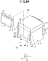
- FIG. 10 is an exploded perspective view of the thermal printer according to the third embodiment.
- illustration of the second cable 104 connecting the display unit 7 and the housing 2 to each other is omitted.
- the display unit 7 is removably mounted on the mounting surface 23A of the housing 2 with a configuration different from those of the first embodiment. This configuration is described below. Description of the same configuration as that of the first embodiment is omitted.
- a display unit arrangement portion 302 is formed so as to be recessed in the mounting surface 23A of the housing 2. Unlike the display unit arrangement portion 26 in the first embodiment and the second embodiment (see FIG. 5 and FIG. 8 ), the display unit arrangement portion 302 is formed with an upper side thereof being opened. With this, the display unit mounting portion 72 of the display unit 7 can be slid to be inserted into the display unit arrangement portion 302 of the housing 2 from above.
- a pair of holding portions 303 and 303 are arranged so as to be opposed to each other in the edge portions 27 and 27 on the right and left sides of the display unit arrangement portion 302. The pair of holding portions 303 and 303 are formed so as to extend along the edge portions 27 and 27.
- the holding portion 303 may have a trapezoidal shape in cross section having a short side in the backward direction and a long side in the forward direction.
- a pair of grooves 304 and 304 are formed between the display unit arrangement portion 302 of the mounting surface 23A and the pair of holding portions 303 and 303.
- the pair of grooves 304 and 304 are arranged so as to be opposed to each other along the edge portions on the right and left sides of the display unit arrangement portion 302.
- the display unit mounting portion 72 of the display unit 7 is fitted in the display unit arrangement portion 302 with the right and left sides of the display unit mounting portion 72 being inserted in the pair of grooves 304 and 304. With this, the display unit 7 is removably mounted on the mounting surface 23A of the housing 2.
- the lower part of the display unit mounting portion 72 is brought into abutment against the step portion 29 on a lower side of the display unit arrangement portion 302 to be locked thereon. With this, the display unit 7 is held by the pair of holding portions 303 and 303 and the step portion 29 to be removably mounted on the mounting surface 23A of the housing 2.
- the display unit 7 is mounted on the mounting surface 23A through insertion of both sides of the display unit 7 into the pair of grooves 304 and 304. Therefore, the display unit 7 can be easily mounted on and removed from the mounting surface 23A by only sliding the display unit 7 along the grooves 304. Thus, according to the present invention, the mounting and removing operation of the display unit 7 can be easily performed.
- the display unit 7 includes the display unit main body 71 and the display unit mounting portion 72.
- the display unit 7 may be formed of only the display unit main body 71, and the display unit main body 71 may be directly mounted on the mounting surface 23A.
- the predetermined information to be displayed on the display unit 7 there is given payment information.
- information such as store information and bargain information may be displayed besides the payment information.
- required information may be displayed in accordance with a place of use of the thermal printers 1, 201, and 301.
- the mounting surface 23A on which the display unit 7 is mounted is formed on the back surface 23 on a side opposite to the front surface 22 having an opening.
- the position of the mounting surface 23A is not limited to that in the above-mentioned embodiments.
- the mounting surface 23A may be formed on any one of right and left side surfaces adjacent to the front surface 22, or on an upper surface on a side opposite to the bottom surface 21.
- the present invention is applied to the thermal printers 1, 201, and 301 of the forward delivery type in which the recording paper P is delivered in the forward direction.
- the present invention may be applied to, for example, a thermal printer of an upward delivery type in which the recording paper P is delivered in the upward direction.
- description is given of the example in which the present invention is applied to the thermal printers 1, 201, and 301 as an example of the printer.
- the present invention may be applied to printers other than the thermal printers 1, 201, and 301.
- the present invention may be applied to an inkjet printer in which printing is performed on recording paper through use of ink droplets.
- the pair of sandwiching portions 28 and 28 are arranged so as to be opposed to each other in the edge portions 27 and 27 on the right and left sides of the display unit arrangement portion 26, and the display unit mounting portion 72 is sandwiched by the pair of sandwiching portions 28 and 28.
- the number of pairs of the sandwiching portions 28 and 28 is not limited to one pair.
- a plurality of pairs of sandwiching portions 28 and 28 may be arranged, and the display unit mounting portion 72 may be sandwiched by the plurality of pairs of sandwiching portions 28 and 28.
- the display unit mounting portion 72 of the display unit 72 can be slid to be inserted into the display unit arrangement portion 302 of the housing 2 from above.
- the display unit mounting portion 72 of the display unit 7 may be slid to be inserted into the display unit arrangement portion 302 of the housing 2 from any one of the right direction and the left direction with the pair of grooves 304 and 304 formed on the upper and lower sides of the mounting surface 23A.
Landscapes
- Engineering & Computer Science (AREA)
- Multimedia (AREA)
- Signal Processing (AREA)
- Accessory Devices And Overall Control Thereof (AREA)
- Physics & Mathematics (AREA)
- General Physics & Mathematics (AREA)
- Particle Formation And Scattering Control In Inkjet Printers (AREA)
- Massaging Devices (AREA)
Abstract
Description
- The present invention relates to a printer.
- There has hitherto been known a printer, which is to be used for a point-of-sale system (POS), and includes a display unit configured to display predetermined information and a printer main body portion connected to the display unit through a cable. In this related-art printer, the display unit is arranged on a printer stand configured to support the printer main body portion.
- However, in the above-mentioned related-art printer, an installation space for the printer stand is required, and hence there is room for improvement from the viewpoint of space saving at a time of installing the printer including the display unit connected to the printer main body portion through the cable.
- In view of the foregoing, in this type of printer, there is a demand for a printer capable of effectively achieving space saving even when the printer includes the display unit connected to the printer main body portion through the cable.
- According to one embodiment of the present invention, there is provided a printer, including: a housing, which has a recording paper receiving portion having an opening, and includes a plurality of outer surfaces including a bottom surface to be opposed to an installation surface; a printer cover, which is coupled to the housing, and is capable of opening and closing the opening; a display unit, which is removably mounted on a mounting surface other than the bottom surface among the plurality of outer surfaces, and is configured to display predetermined information; a cable having one end connected to the display unit and another end on which a connector is mounted; and a connector connecting portion to which the connector is connected.
- In the above-mentioned printer according to the one embodiment of the present invention, wherein the housing has a box shape, wherein the opening is formed on a side, and wherein the mounting surface comprises a side surface on a side opposite to the opening among the plurality of outer surfaces.
- In the above-mentioned printer according to the one embodiment of the present invention, wherein the display unit includes a display region on which the predetermined information is displayed, and wherein the display region has a size set to a region corresponding to the mounting surface.
- In the above-mentioned printer according to the one embodiment of the present invention, wherein the connector connecting portion is formed in a lower part of the mounting surface.
- In the above-mentioned printer according to the one embodiment of the present invention, wherein a recessed portion that is recessed inward from the mounting surface is formed in the lower part of the mounting surface, and wherein the connector connecting portion is formed in the recessed portion.
- In the above-mentioned printer according to the one embodiment of the present invention, wherein the mounting surface has both edge portions in which a pair of elastically deformable sandwiching portions are formed, and wherein the display unit is mounted on the mounting surface so as to be sandwiched by the pair of elastically deformable sandwiching portions.
- In the above-mentioned printer according to the one embodiment of the present invention, wherein the display unit is mounted on the mounting surface with a fastening member.
- In the above-mentioned printer according to the one embodiment of the present invention, wherein, on both sides of the mounting surface, a pair of grooves are formed so as to be opposed to each other along the both sides, and wherein the display unit is mounted on the mounting surface through insertion of both sides of the display unit into the pair of grooves.
- Embodiments of the present invention will now be described by way of further example only and with reference to the accompanying drawings, in which:
-
FIG. 1 is a block diagram of a POS including a thermal printer according to a first embodiment of the present invention. -
FIG. 2 is a perspective view of the thermal printer according to the first embodiment in a state in which a printer cover is closed. -
FIG. 3 is a perspective view of the thermal printer according to the first embodiment in a state in which the printer cover is opened. -
FIG. 4 is a perspective view of the thermal printer according to the first embodiment when viewed from a back surface side. -
FIG. 5 is an exploded perspective view of the thermal printer according to the first embodiment. -
FIG. 6 is a sectional view of the thermal printer taken along the line VI-VI ofFIG. 5 . -
FIG. 7 is a perspective view of a thermal printer according to a second embodiment of the present invention when viewed from a back surface side. -
FIG. 8 is an exploded perspective view of the thermal printer according to the second embodiment. -
FIG. 9 is a perspective view of a thermal printer according to a third embodiment of the present invention when viewed from a back surface side. -
FIG. 10 is an exploded perspective view of the thermal printer according to the third embodiment. - Now, a first embodiment of the present invention is described with reference to the drawings.
FIG. 1 is a block diagram of a point-of-sale system (POS) including a thermal printer according to the first embodiment. A POS 101 is installed in commercial places such as retail stores and restaurants. The POS 101 is a system configured to notify customers of payment information (predetermined information) such as names and prices of products purchased by the customers. - As illustrated in
FIG. 1 , thePOS 101 includes aninformation processing device 102 and a thermal printer 1 (corresponding to the "printer" in claims). Theinformation processing device 102 is configured to perform, for example, payment processing for the products. Theinformation processing device 102 is configured to control the operation of thethermal printer 1. As examples of theinformation processing device 102, there are given personal computers of a desktop type and a tablet type. Thethermal printer 1 is installed on a store counter. - The
thermal printer 1 includes a printermain body 11 and adisplay unit 7. The printermain body 11 and theinformation processing device 102 are connected to each other through afirst cable 103, for example, a universal serial bus (USB) cable. The printermain body 11 and theinformation processing device 102 may be wirelessly connected to each other. The operation of the printermain body 11 is controlled by theinformation processing device 102. The printermain body 11 is configured to print data such as payment information sent from theinformation processing device 102 on recording paper P (seeFIG. 2 ) such as heat-sensitive paper and deliver the printed recording paper P. - The
display unit 7 and the printermain body 11 are connected to each other through asecond cable 104, for example, a USB cable. With this, thedisplay unit 7 receives electric power supplied from the printermain body 11. Thedisplay unit 7 is connected to theinformation processing device 102 through intermediation of the printermain body 11. With this, thedisplay unit 7 displays the data such as payment information sent from theinformation processing device 102. -
FIG. 2 is a perspective view of the thermal printer according to the first embodiment in a state in which a printer cover is closed.FIG. 3 is a perspective view of the thermal printer according to the first embodiment in a state in which the printer cover is opened. InFIG. 2 and subsequent figures, an upper side of the drawing sheet is defined as an upward direction (upward direction in a gravity direction), and a lower side of the drawing sheet is defined as a downward direction (downward direction in the gravity direction). Further, a front-and-back direction is denoted by L1. An up-and-down direction is denoted by L2. A direction orthogonal to the front-and-back direction L1 and the up-and-down direction L2 is defined as a right-and-left direction L3. Further, a forward direction is indicated by the arrow FW, and a backward direction is indicated by the arrow BA. - As illustrated in
FIG. 2 , thethermal printer 1 is a printer of a "forward delivery" type in which the recording paper P is delivered in the forward direction (on afront surface 22 side of the thermal printer 1). Thethermal printer 1 is used in a state in which the forward direction thereof is directed to, for example, a store clerk who is a first user, and the backward direction thereof is directed to, for example, a store customer who is a second user. This usage state of thethermal printer 1 is merely an example, and there is no particular limitation on the usage state. - The printer
main body 11 includes ahousing 2 and aprinter cover 3. Thehousing 2 is installed on aninstallation surface 110 in a store. As illustrated inFIG. 3 , thehousing 2 has a box shape having anopening 25 in the forward direction. Thehousing 2 has a plurality of outer surfaces including abottom surface 21, thefront surface 22, and aback surface 23. Thebottom surface 21 is formed, in a large part, so as to be opposed to theinstallation surface 110 in a state of being separated therefrom. Thefront surface 22 is formed of theprinter cover 3 arranged in the opening 25. Theback surface 23 forms a mountingsurface 23A on which the display unit 7 (seeFIG. 4 andFIG. 5 ) described later is removably mounted. The mountingsurface 23A is positioned on a side opposite to thefront surface 22. - As illustrated in
FIG. 2 , theprinter cover 3 is coupled to a lower part of thehousing 2 so as to open and close theopening 25 of thehousing 2. A delivery slot 12 (gap) is formed between a distal end part of theprinter cover 3 and thehousing 2. The recording paper P is delivered in the forward direction from an inside of thehousing 2 through thedelivery slot 12. As illustrated inFIG. 3 , the recordingpaper receiving portion 10 is formed in thehousing 2. The recording paper P is received in the recordingpaper receiving portion 10 in a state of being wound into a tubular shape having an axial line extending along the right-and-left direction L3. - A platen unit 4 is provided on a back surface of the
printer cover 3. The platen unit 4 is a component of the printermain body 11. The platen unit 4 is configured to send out the recording paper P in the forward direction from the delivery slot 12 (seeFIG. 2 ). - A
head unit 5 is provided in the upward direction of the recordingpaper receiving portion 10 in thehousing 2. Thehead unit 5 is a component of the printermain body 11. Thehead unit 5 is electrically connected to theinformation processing device 102 through thefirst cable 103. Thehead unit 5 is configured to print, on the recording paper P, data such as payment information sent from theinformation processing device 102. -
FIG. 4 is a perspective view of the thermal printer according to the first embodiment when viewed from the back surface side.FIG. 5 is an exploded perspective view of the thermal printer according to the first embodiment. As illustrated inFIG. 4 andFIG. 5 , thedisplay unit 7 is removably mounted on the mountingsurface 23A of thehousing 2. Thedisplay unit 7 includes a display unitmain body 71 and a displayunit mounting portion 72. - The display unit
main body 71 has a plate shape. One end of the second cable 104 (seeFIG. 5 ) is connected to the display unitmain body 71. One end of thesecond cable 104 may be removably connected to the display unitmain body 71, for example, through a connector (not shown). A display screen 73 (corresponding to the "display region" in the claims) is provided on the display unitmain body 71. Data such as payment information sent from theinformation processing device 102 are displayed in forms of characters and images on thedisplay screen 73. The size of the display screen 73 (size of the display region) is set to a region corresponding to the mountingsurface 23A. - As illustrated in
FIG. 5 , the displayunit mounting portion 72 has a plate shape. The displayunit mounting portion 72 is mounted on the mountingsurface 23A of thehousing 2. An upper part of the displayunit mounting portion 72 is pivotably mounted on an upper part of the display unitmain body 71 through intermediation ofpivot portions 74 formed of, for example, hinges. With thepivot portions 74, thedisplay screen 73 of the display unitmain body 71 can be changed in angle with respect to the mountingsurface 23A. - A display
unit arrangement portion 26 is formed so as to be recessed in the mountingsurface 23A of thehousing 2. The displayunit mounting portion 72 is arranged in the displayunit arrangement portion 26. The movement of a lower part of the displayunit mounting portion 72 is regulated by holding the lower part of the displayunit mounting portion 72 in abutment against astep portion 29 on a lower side of the displayunit arrangement portion 26. - A pair of sandwiching
portions edge portions unit arrangement portion 26. The pair of sandwichingportions unit mounting portion 72 are sandwiched by the pair of sandwichingportions unit mounting portion 72 are sandwiched by the pair of sandwichingportions - A specific configuration of the sandwiching
portion 28 is described. The sandwichingportion 28 includes abase portion 281 and a lockingclaw 282. Thebase portion 281 is connected to theedge portion 27. Thebase portion 281 extends in the up-and-down direction L2 that is an extending direction of theedge portion 27 and protrudes in the backward direction. The lockingclaw 282 is formed at a distal end of thebase portion 281. The lockingclaw 282 has a triangular shape in cross section. The displayunit mounting portion 72 is locked on inner sides of the lockingclaws base portions 281. Thedisplay unit 7 can be mounted on and removed from the mountingsurface 23A by elastically deforming thebase portions portions -
FIG. 6 is a sectional view of the thermal printer taken along the line VI-VI ofFIG. 5 . As illustrated inFIG. 6 , a recessedportion 82 is formed in a lower part of the mountingsurface 23A. The recessedportion 82 is formed so as to be recessed inward from the mountingsurface 23A (toward an inner side of the housing 2). The recessedportion 82 has an L-shape in side sectional view. Aconnector connecting portion 81 is formed in the recessedportion 82. Theconnector connecting portion 81 is formed on aside surface 83 facing the front-and-back direction L1 in the recessedportion 82. Aconnector 105 mounted on thesecond cable 104 is connected to theconnector connecting portion 81 so as to be mountable on and removable from theconnector connecting portion 81 through insertion and removal of theconnector 105 along the front-and-back direction L1. For example, a locking portion capable of accommodating thesecond cable 104 by locking thesecond cable 104 may be formed in the recessedportion 82. - According to this embodiment, the
display unit 7 is removably mounted on the mountingsurface 23A of thehousing 2 other than thebottom surface 21 among the plurality of outer surfaces. Therefore, thedisplay unit 7 can be supported without the printer stand used in the related art. With this, an installation space for the printer stand is not required. Thus, even when thedisplay unit 7 connected through thesecond cable 104 is provided, space saving can be achieved as compared to the related art. Further, the printer stand is not required, and hence thethermal printer 1 including thedisplay unit 7 connected through thesecond cable 104 can be installed at low cost. Further, thedisplay unit 7 can be mounted on and removed from the mountingsurface 23A of thehousing 2. Therefore, thethermal printer 1 can be adapted for a user who does not require thedisplay unit 7 as well as a user who requires thedisplay unit 7. Thus, thethermal printer 1, which is excellent in versatility and has a high degree of freedom in design, can be obtained. - Further, according to this embodiment, the mounting
surface 23A on which thedisplay unit 7 is mounted is a side surface on a side opposite to theopening 25 in which theprinter cover 3 is arranged among the plurality of outer surfaces. Therefore, thedisplay unit 7 can be provided on a side opposite to theprinter cover 3. In general, thedelivery slot 12 of the recording paper P of thethermal printer 1 is formed on theopening 25 side in many cases. Thus, according to this embodiment, thethermal printer 1 can be used in a state in which thedelivery slot 12 of the recording paper P of thethermal printer 1 is directed to the first user (for example, the store clerk) and thedisplay unit 7 of thethermal printer 1 is directed to the second user (for example, the store customer). Therefore, thethermal printer 1, which is easy to use and excellent in operability, can be obtained. - Further, according to this embodiment, the size of the
display screen 73 is set to the region corresponding to the mountingsurface 23A. Therefore, the predetermined information can be displayed on thedisplay screen 73 of thedisplay unit 7 while being enlarged to the largest possible size. Thus, thethermal printer 1 according to this embodiment enables a user to easily visually recognize the predetermined information. - Further, according to this embodiment, the
display unit 7 is mounted on the mountingsurface 23A while being sandwiched by the pair of sandwichingportions display unit 7 can be easily mounted on and removed from the mountingsurface 23A by elastically deforming the pair of sandwichingportions thermal printer 1, which is easy to use and excellent in operability, can be obtained. - Further, according to this embodiment, the
connector connecting portion 81 is formed in the lower part of the mountingsurface 23A. Therefore, theconnector 105 provided at another end of thesecond cable 104 is connected to the lower part of the mountingsurface 23A through intermediation of theconnector connecting portion 81. With this, thesecond cable 104 is prevented from being caught by other components, for example, at a time of use or transport, and hence theconnector 105 of thesecond cable 104 can be prevented from being unexpectedly removed from theconnector connecting portion 81. - Further, according to this embodiment, the
connector connecting portion 81 is formed in the recessedportion 82 that is recessed inward from the mountingsurface 23A. Therefore, theconnector 105 at another end of thesecond cable 104 is connected to the lower part of the mountingsurface 23A through intermediation of theconnector connecting portion 81 in the recessedportion 82. With this, thesecond cable 104 can be accommodated in the recessedportion 82, and exposure of theconnector 105 to outside is suppressed. Thus, theconnector 105 of thesecond cable 104 can be further prevented from being unexpectedly removed from theconnector connecting portion 81. - Next, a
thermal printer 201 according to a second embodiment of the present invention is described.FIG. 7 is a perspective view of the thermal printer according to the second embodiment when viewed from a back surface side.FIG. 8 is an exploded perspective view of the thermal printer according to the second embodiment. InFIG. 8 , illustration of thesecond cable 104 connecting thedisplay unit 7 and thehousing 2 to each other is omitted. In thethermal printer 201 according to the second embodiment, thedisplay unit 7 is removably mounted on the mountingsurface 23A of thehousing 2 with a configuration different from that of the first embodiment. This configuration is described below. Description of the same configuration as that of the first embodiment is omitted. - As illustrated in
FIG. 7 andFIG. 8 , thedisplay unit 7 of thethermal printer 201 according to the second embodiment is removably mounted on the mountingsurface 23A of thehousing 2 with a plurality of screws 202 (corresponding to the "fastening member" in claims). In the mountingsurface 23A of thehousing 2, a plurality offemale thread portions 203 are formed in the displayunit arrangement portion 26. The plurality offemale thread portions 203 are arranged at four corners of the displayunit arrangement portion 26. A plurality of throughholes 204 are formed in the displayunit mounting portion 72 of thedisplay unit 7. The plurality of throughholes 204 are arranged at four corners of the displayunit mounting portion 72, which are positions corresponding to the plurality offemale thread portions 203 in the displayunit mounting portion 72. The plurality ofscrews 202 are inserted into the throughholes 204 of the displayunit mounting portion 72 to be threadedly engaged with the plurality offemale thread portions 203. With this, thedisplay unit 7 is removably mounted on the mountingsurface 23A of thehousing 2 with the plurality ofscrews 202. - According to this embodiment, the
display unit 7 is mounted on the mountingsurface 23A by threadedly engaging the plurality ofscrews 202 with thefemale thread portions 203. Therefore, thedisplay unit 7 can be reliably and firmly mounted on the mountingsurface 23A. Thus, according to this embodiment, thedisplay unit 7 can be prevented from being unexpectedly removed from the mountingsurface 23A due to vibration or the like. Further, thedisplay unit 7 can be easily removed from the mountingsurface 23A of thehousing 2 by releasing thescrews 202 from thefemale thread portions 203. Thus, according to this embodiment, the mounting and removing operation of thedisplay unit 7 can be easily performed. - Next, a
thermal printer 301 according to a third embodiment of the present invention is described.FIG. 9 is a perspective view of the thermal printer according to the third embodiment when viewed from a back surface side.FIG. 10 is an exploded perspective view of the thermal printer according to the third embodiment. InFIG. 10 , illustration of thesecond cable 104 connecting thedisplay unit 7 and thehousing 2 to each other is omitted. In thethermal printer 301 according to the third embodiment, thedisplay unit 7 is removably mounted on the mountingsurface 23A of thehousing 2 with a configuration different from those of the first embodiment. This configuration is described below. Description of the same configuration as that of the first embodiment is omitted. - As illustrated in
FIG. 9 andFIG. 10 , a displayunit arrangement portion 302 is formed so as to be recessed in the mountingsurface 23A of thehousing 2. Unlike the displayunit arrangement portion 26 in the first embodiment and the second embodiment (seeFIG. 5 andFIG. 8 ), the displayunit arrangement portion 302 is formed with an upper side thereof being opened. With this, the displayunit mounting portion 72 of thedisplay unit 7 can be slid to be inserted into the displayunit arrangement portion 302 of thehousing 2 from above. A pair of holdingportions edge portions unit arrangement portion 302. The pair of holdingportions edge portions portion 303 may have a trapezoidal shape in cross section having a short side in the backward direction and a long side in the forward direction. A pair ofgrooves unit arrangement portion 302 of the mountingsurface 23A and the pair of holdingportions - The pair of
grooves unit arrangement portion 302. The displayunit mounting portion 72 of thedisplay unit 7 is fitted in the displayunit arrangement portion 302 with the right and left sides of the displayunit mounting portion 72 being inserted in the pair ofgrooves display unit 7 is removably mounted on the mountingsurface 23A of thehousing 2. The lower part of the displayunit mounting portion 72 is brought into abutment against thestep portion 29 on a lower side of the displayunit arrangement portion 302 to be locked thereon. With this, thedisplay unit 7 is held by the pair of holdingportions step portion 29 to be removably mounted on the mountingsurface 23A of thehousing 2. - According to this embodiment, the
display unit 7 is mounted on the mountingsurface 23A through insertion of both sides of thedisplay unit 7 into the pair ofgrooves display unit 7 can be easily mounted on and removed from the mountingsurface 23A by only sliding thedisplay unit 7 along thegrooves 304. Thus, according to the present invention, the mounting and removing operation of thedisplay unit 7 can be easily performed. - Note that, the technical scope of the present invention is not limited to the above-mentioned embodiment, but various modifications may be made without departing from the scope of claims.
- In the above-mentioned embodiments, the
display unit 7 includes the display unitmain body 71 and the displayunit mounting portion 72. However, thedisplay unit 7 may be formed of only the display unitmain body 71, and the display unitmain body 71 may be directly mounted on the mountingsurface 23A. Further, in the above-mentioned embodiments, as an example of the predetermined information to be displayed on thedisplay unit 7, there is given payment information. However, information such as store information and bargain information may be displayed besides the payment information. Further, required information may be displayed in accordance with a place of use of thethermal printers - In the above-mentioned embodiments, the mounting
surface 23A on which thedisplay unit 7 is mounted is formed on theback surface 23 on a side opposite to thefront surface 22 having an opening. However, the position of the mountingsurface 23A is not limited to that in the above-mentioned embodiments. Thus, for example, the mountingsurface 23A may be formed on any one of right and left side surfaces adjacent to thefront surface 22, or on an upper surface on a side opposite to thebottom surface 21. - In the above-mentioned embodiments, description is given of the example in which the present invention is applied to the
thermal printers thermal printers thermal printers - In the first embodiment, the pair of sandwiching
portions edge portions unit arrangement portion 26, and the displayunit mounting portion 72 is sandwiched by the pair of sandwichingportions portions portions unit mounting portion 72 may be sandwiched by the plurality of pairs of sandwichingportions - In the
thermal printer 301 according to the third embodiment, with the pair ofgrooves surface 23A, the displayunit mounting portion 72 of thedisplay unit 72 can be slid to be inserted into the displayunit arrangement portion 302 of thehousing 2 from above. Meanwhile, the displayunit mounting portion 72 of thedisplay unit 7 may be slid to be inserted into the displayunit arrangement portion 302 of thehousing 2 from any one of the right direction and the left direction with the pair ofgrooves surface 23A. - Besides the above, the components in the above-mentioned embodiments may be replaced by well-known components as appropriate without departing from the scope of the claims . The above-mentioned modified examples may be combined with each other as appropriate.
Claims (8)
- A printer (1), comprising:a housing (2), which has a recording paper receiving portion (10) having an opening (25), and includes a plurality of outer surfaces including a bottom surfaces (21) to be opposed to an installation surface (110);a printer (1) cover, which is coupled to the housing (2), and is capable of opening and closing the opening (25);a display unit (7), which is removably mounted on a mounting surface (23A) other than the bottom surfaces (21) among the plurality of outer surfaces, and is configured to display predetermined information;a cable having one end connected to the display unit (7) and another end on which a connector (105) is mounted; anda connector connecting portion (81) to which the connector (105) is connected.
- A printer (1) according to claim 1,
wherein the housing (2) has a box shape,
wherein the opening (25) is formed on a side, and
wherein the mounting surface (23A) comprises a side surface on a side opposite to the opening (25) among the plurality of outer surfaces. - A printer (1) according to claim 1 or claim 2,
wherein the display unit (7) includes a display region (73) on which the predetermined information is displayed, and
wherein the display region (73) has a size set to a region corresponding to the mounting surface (23A). - A printer (1) according to any one of the preceding claims, wherein the connector connecting portion (81) is formed in a lower part of the mounting surface (23A).
- A printer (1) according to claim 4,
wherein a recessed portion (82) that is recessed inward from the mounting surface (23A) is formed in the lower part of the mounting surface (23A), and
wherein the connector connecting portion (81) is formed in the recessed portion (82). - A printer (1) according to any one of the preceding claims,
wherein the mounting surface (23A) has both edge portions (27, 27) in which a pair of elastically deformable sandwiching portions (28, 28) are formed, and
wherein the display unit (7) is mounted on the mounting surface (23A) so as to be sandwiched by the pair of elastically deformable sandwiching portions (28, 28). - A printer (1) according to any one of claims 1 to 5, wherein the display unit (7) is mounted on the mounting surface (23A) with a fastening member.
- A printer (1) according to any one of claims 1 to 5,
wherein, on both sides of the mounting surface (23A), a pair of grooves (304, 304) are formed so as to be opposed to each other along the both sides, and
wherein the display unit (7) is mounted on the mounting surface (23A) through insertion of both sides of the display unit (7) into the pair of grooves (304, 304).
Priority Applications (1)
| Application Number | Priority Date | Filing Date | Title |
|---|---|---|---|
| EP20154619.9A EP3680109B1 (en) | 2017-12-08 | 2018-12-07 | Printer |
Applications Claiming Priority (1)
| Application Number | Priority Date | Filing Date | Title |
|---|---|---|---|
| JP2017235691A JP6974149B2 (en) | 2017-12-08 | 2017-12-08 | Printer |
Related Child Applications (2)
| Application Number | Title | Priority Date | Filing Date |
|---|---|---|---|
| EP20154619.9A Division-Into EP3680109B1 (en) | 2017-12-08 | 2018-12-07 | Printer |
| EP20154619.9A Division EP3680109B1 (en) | 2017-12-08 | 2018-12-07 | Printer |
Publications (2)
| Publication Number | Publication Date |
|---|---|
| EP3495152A1 true EP3495152A1 (en) | 2019-06-12 |
| EP3495152B1 EP3495152B1 (en) | 2024-11-27 |
Family
ID=64661124
Family Applications (2)
| Application Number | Title | Priority Date | Filing Date |
|---|---|---|---|
| EP18210935.5A Active EP3495152B1 (en) | 2017-12-08 | 2018-12-07 | Printer |
| EP20154619.9A Active EP3680109B1 (en) | 2017-12-08 | 2018-12-07 | Printer |
Family Applications After (1)
| Application Number | Title | Priority Date | Filing Date |
|---|---|---|---|
| EP20154619.9A Active EP3680109B1 (en) | 2017-12-08 | 2018-12-07 | Printer |
Country Status (6)
| Country | Link |
|---|---|
| US (1) | US10752032B2 (en) |
| EP (2) | EP3495152B1 (en) |
| JP (1) | JP6974149B2 (en) |
| KR (1) | KR102716683B1 (en) |
| CN (2) | CN109910445B (en) |
| TW (1) | TWI772560B (en) |
Cited By (2)
| Publication number | Priority date | Publication date | Assignee | Title |
|---|---|---|---|---|
| EP3666536A1 (en) * | 2018-12-11 | 2020-06-17 | Seiko Instruments Inc. | Printer and printer display device |
| USD897421S1 (en) * | 2018-08-07 | 2020-09-29 | Seiko Instruments Inc. | Printer |
Families Citing this family (3)
| Publication number | Priority date | Publication date | Assignee | Title |
|---|---|---|---|---|
| JP6974149B2 (en) * | 2017-12-08 | 2021-12-01 | セイコーインスツル株式会社 | Printer |
| JP7468195B2 (en) * | 2020-06-30 | 2024-04-16 | セイコーエプソン株式会社 | Printing device |
| CN114987066B (en) * | 2022-07-06 | 2023-07-18 | 时时同云科技(成都)有限责任公司 | Printer and cashier device |
Citations (3)
| Publication number | Priority date | Publication date | Assignee | Title |
|---|---|---|---|---|
| US20110261394A1 (en) * | 2010-04-26 | 2011-10-27 | Atsushi Tanaka | Printer stand |
| EP3075557A2 (en) * | 2015-03-31 | 2016-10-05 | Brother Kogyo Kabushiki Kaisha | Print device |
| US20170021651A1 (en) * | 2015-07-24 | 2017-01-26 | Seiko Epson Corporation | Recording apparatus |
Family Cites Families (9)
| Publication number | Priority date | Publication date | Assignee | Title |
|---|---|---|---|---|
| GB2243336A (en) * | 1990-04-24 | 1991-10-30 | Esselte Meto Int Gmbh | Portable printers. |
| JP2002361971A (en) * | 2001-06-11 | 2002-12-18 | Ricoh Co Ltd | Image forming device |
| JP4020779B2 (en) * | 2002-12-18 | 2007-12-12 | 株式会社リコー | Angle adjustment device for operation panel |
| JP4260474B2 (en) * | 2002-12-27 | 2009-04-30 | シャープ株式会社 | Facsimile machine |
| CN1265970C (en) * | 2003-05-23 | 2006-07-26 | 诚研科技股份有限公司 | Printers with separate controls |
| JP2009282065A (en) * | 2008-05-19 | 2009-12-03 | Ricoh Co Ltd | Image forming apparatus |
| JP5748096B2 (en) * | 2011-02-09 | 2015-07-15 | 株式会社リコー | Electronic device and information display method |
| JP6974149B2 (en) * | 2017-12-08 | 2021-12-01 | セイコーインスツル株式会社 | Printer |
| JP7232619B2 (en) * | 2018-10-30 | 2023-03-03 | セイコーインスツル株式会社 | Printer system, printer, printer system control method, and printer control method |
-
2017
- 2017-12-08 JP JP2017235691A patent/JP6974149B2/en active Active
-
2018
- 2018-11-22 TW TW107141599A patent/TWI772560B/en active
- 2018-12-05 KR KR1020180155193A patent/KR102716683B1/en active Active
- 2018-12-06 US US16/211,852 patent/US10752032B2/en active Active
- 2018-12-07 EP EP18210935.5A patent/EP3495152B1/en active Active
- 2018-12-07 CN CN201811491739.1A patent/CN109910445B/en active Active
- 2018-12-07 CN CN201822056641.5U patent/CN209683205U/en active Active
- 2018-12-07 EP EP20154619.9A patent/EP3680109B1/en active Active
Patent Citations (3)
| Publication number | Priority date | Publication date | Assignee | Title |
|---|---|---|---|---|
| US20110261394A1 (en) * | 2010-04-26 | 2011-10-27 | Atsushi Tanaka | Printer stand |
| EP3075557A2 (en) * | 2015-03-31 | 2016-10-05 | Brother Kogyo Kabushiki Kaisha | Print device |
| US20170021651A1 (en) * | 2015-07-24 | 2017-01-26 | Seiko Epson Corporation | Recording apparatus |
Cited By (3)
| Publication number | Priority date | Publication date | Assignee | Title |
|---|---|---|---|---|
| USD897421S1 (en) * | 2018-08-07 | 2020-09-29 | Seiko Instruments Inc. | Printer |
| EP3666536A1 (en) * | 2018-12-11 | 2020-06-17 | Seiko Instruments Inc. | Printer and printer display device |
| US10899148B2 (en) | 2018-12-11 | 2021-01-26 | Seiko Instruments Inc. | Printer and printer display device |
Also Published As
| Publication number | Publication date |
|---|---|
| TW201934356A (en) | 2019-09-01 |
| CN209683205U (en) | 2019-11-26 |
| CN109910445A (en) | 2019-06-21 |
| US20190176497A1 (en) | 2019-06-13 |
| TWI772560B (en) | 2022-08-01 |
| KR102716683B1 (en) | 2024-10-14 |
| CN109910445B (en) | 2022-05-27 |
| KR20190068451A (en) | 2019-06-18 |
| EP3495152B1 (en) | 2024-11-27 |
| EP3680109B1 (en) | 2024-11-20 |
| JP6974149B2 (en) | 2021-12-01 |
| JP2019098714A (en) | 2019-06-24 |
| EP3680109A1 (en) | 2020-07-15 |
| US10752032B2 (en) | 2020-08-25 |
Similar Documents
| Publication | Publication Date | Title |
|---|---|---|
| US10752032B2 (en) | Printer | |
| JP7166161B2 (en) | Printers and display devices for printers | |
| US12260139B2 (en) | Printing apparatus | |
| US10899148B2 (en) | Printer and printer display device | |
| US6421133B2 (en) | Hybrid printer, printer mounting base and printer that is mountable on printer mounting base | |
| EP3001160A1 (en) | Attached printer for a weighing scale | |
| US11942736B2 (en) | Electronic device | |
| US20230068350A1 (en) | Printing apparatus | |
| US12057666B2 (en) | Electronic device | |
| US20230061909A1 (en) | Printing apparatus | |
| US9721440B1 (en) | Point-of-sale system with replaceable printer | |
| JP2022161377A (en) | printer | |
| EP3537396A1 (en) | Sales registration apparatus | |
| US20230063832A1 (en) | Electronic device | |
| EP3647935A1 (en) | Printer system, printer, method of controlling printer system, and method of controlling printer | |
| CN204367592U (en) | Print unit, connector cover and jockey | |
| CN214295118U (en) | Receipt printer | |
| US7513705B1 (en) | Toolless thermal print head mounting apparatus | |
| JP2014146157A (en) | Information processing apparatus | |
| TH25285A (en) | A POS terminal with replaceable printer ink cartridges. |
Legal Events
| Date | Code | Title | Description |
|---|---|---|---|
| PUAI | Public reference made under article 153(3) epc to a published international application that has entered the european phase |
Free format text: ORIGINAL CODE: 0009012 |
|
| STAA | Information on the status of an ep patent application or granted ep patent |
Free format text: STATUS: THE APPLICATION HAS BEEN PUBLISHED |
|
| AK | Designated contracting states |
Kind code of ref document: A1 Designated state(s): AL AT BE BG CH CY CZ DE DK EE ES FI FR GB GR HR HU IE IS IT LI LT LU LV MC MK MT NL NO PL PT RO RS SE SI SK SM TR |
|
| AX | Request for extension of the european patent |
Extension state: BA ME |
|
| STAA | Information on the status of an ep patent application or granted ep patent |
Free format text: STATUS: REQUEST FOR EXAMINATION WAS MADE |
|
| 17P | Request for examination filed |
Effective date: 20191212 |
|
| RBV | Designated contracting states (corrected) |
Designated state(s): AL AT BE BG CH CY CZ DE DK EE ES FI FR GB GR HR HU IE IS IT LI LT LU LV MC MK MT NL NO PL PT RO RS SE SI SK SM TR |
|
| STAA | Information on the status of an ep patent application or granted ep patent |
Free format text: STATUS: EXAMINATION IS IN PROGRESS |
|
| 17Q | First examination report despatched |
Effective date: 20201215 |
|
| REG | Reference to a national code |
Ref country code: DE Ref legal event code: R079 Ref document number: 602018076914 Country of ref document: DE Free format text: PREVIOUS MAIN CLASS: B41J0029130000 Ipc: H04N0001000000 |
|
| GRAP | Despatch of communication of intention to grant a patent |
Free format text: ORIGINAL CODE: EPIDOSNIGR1 |
|
| STAA | Information on the status of an ep patent application or granted ep patent |
Free format text: STATUS: GRANT OF PATENT IS INTENDED |
|
| RIC1 | Information provided on ipc code assigned before grant |
Ipc: B41J 3/46 20060101ALI20240701BHEP Ipc: B41J 29/13 20060101ALI20240701BHEP Ipc: H04N 1/00 20060101AFI20240701BHEP |
|
| INTG | Intention to grant announced |
Effective date: 20240711 |
|
| GRAS | Grant fee paid |
Free format text: ORIGINAL CODE: EPIDOSNIGR3 |
|
| GRAA | (expected) grant |
Free format text: ORIGINAL CODE: 0009210 |
|
| STAA | Information on the status of an ep patent application or granted ep patent |
Free format text: STATUS: THE PATENT HAS BEEN GRANTED |
|
| P01 | Opt-out of the competence of the unified patent court (upc) registered |
Free format text: CASE NUMBER: APP_52752/2024 Effective date: 20240920 |
|
| AK | Designated contracting states |
Kind code of ref document: B1 Designated state(s): AL AT BE BG CH CY CZ DE DK EE ES FI FR GB GR HR HU IE IS IT LI LT LU LV MC MK MT NL NO PL PT RO RS SE SI SK SM TR |
|
| REG | Reference to a national code |
Ref country code: GB Ref legal event code: FG4D |
|
| REG | Reference to a national code |
Ref country code: CH Ref legal event code: EP |
|
| REG | Reference to a national code |
Ref country code: DE Ref legal event code: R096 Ref document number: 602018076914 Country of ref document: DE |
|
| REG | Reference to a national code |
Ref country code: IE Ref legal event code: FG4D |
|
| REG | Reference to a national code |
Ref country code: LT Ref legal event code: MG9D |
|
| REG | Reference to a national code |
Ref country code: NL Ref legal event code: MP Effective date: 20241127 |
|
| PG25 | Lapsed in a contracting state [announced via postgrant information from national office to epo] |
Ref country code: PT Free format text: LAPSE BECAUSE OF FAILURE TO SUBMIT A TRANSLATION OF THE DESCRIPTION OR TO PAY THE FEE WITHIN THE PRESCRIBED TIME-LIMIT Effective date: 20250327 Ref country code: IS Free format text: LAPSE BECAUSE OF FAILURE TO SUBMIT A TRANSLATION OF THE DESCRIPTION OR TO PAY THE FEE WITHIN THE PRESCRIBED TIME-LIMIT Effective date: 20250327 Ref country code: HR Free format text: LAPSE BECAUSE OF FAILURE TO SUBMIT A TRANSLATION OF THE DESCRIPTION OR TO PAY THE FEE WITHIN THE PRESCRIBED TIME-LIMIT Effective date: 20241127 |
|
| PG25 | Lapsed in a contracting state [announced via postgrant information from national office to epo] |
Ref country code: FI Free format text: LAPSE BECAUSE OF FAILURE TO SUBMIT A TRANSLATION OF THE DESCRIPTION OR TO PAY THE FEE WITHIN THE PRESCRIBED TIME-LIMIT Effective date: 20241127 Ref country code: NL Free format text: LAPSE BECAUSE OF FAILURE TO SUBMIT A TRANSLATION OF THE DESCRIPTION OR TO PAY THE FEE WITHIN THE PRESCRIBED TIME-LIMIT Effective date: 20241127 |
|
| REG | Reference to a national code |
Ref country code: AT Ref legal event code: MK05 Ref document number: 1746856 Country of ref document: AT Kind code of ref document: T Effective date: 20241127 |
|
| PG25 | Lapsed in a contracting state [announced via postgrant information from national office to epo] |
Ref country code: BG Free format text: LAPSE BECAUSE OF FAILURE TO SUBMIT A TRANSLATION OF THE DESCRIPTION OR TO PAY THE FEE WITHIN THE PRESCRIBED TIME-LIMIT Effective date: 20241127 |
|
| PG25 | Lapsed in a contracting state [announced via postgrant information from national office to epo] |
Ref country code: ES Free format text: LAPSE BECAUSE OF FAILURE TO SUBMIT A TRANSLATION OF THE DESCRIPTION OR TO PAY THE FEE WITHIN THE PRESCRIBED TIME-LIMIT Effective date: 20241127 |
|
| PG25 | Lapsed in a contracting state [announced via postgrant information from national office to epo] |
Ref country code: NO Free format text: LAPSE BECAUSE OF FAILURE TO SUBMIT A TRANSLATION OF THE DESCRIPTION OR TO PAY THE FEE WITHIN THE PRESCRIBED TIME-LIMIT Effective date: 20250227 |
|
| PG25 | Lapsed in a contracting state [announced via postgrant information from national office to epo] |
Ref country code: LV Free format text: LAPSE BECAUSE OF FAILURE TO SUBMIT A TRANSLATION OF THE DESCRIPTION OR TO PAY THE FEE WITHIN THE PRESCRIBED TIME-LIMIT Effective date: 20241127 Ref country code: GR Free format text: LAPSE BECAUSE OF FAILURE TO SUBMIT A TRANSLATION OF THE DESCRIPTION OR TO PAY THE FEE WITHIN THE PRESCRIBED TIME-LIMIT Effective date: 20250228 Ref country code: AT Free format text: LAPSE BECAUSE OF FAILURE TO SUBMIT A TRANSLATION OF THE DESCRIPTION OR TO PAY THE FEE WITHIN THE PRESCRIBED TIME-LIMIT Effective date: 20241127 |
|
| PG25 | Lapsed in a contracting state [announced via postgrant information from national office to epo] |
Ref country code: PL Free format text: LAPSE BECAUSE OF FAILURE TO SUBMIT A TRANSLATION OF THE DESCRIPTION OR TO PAY THE FEE WITHIN THE PRESCRIBED TIME-LIMIT Effective date: 20241127 |
|
| PG25 | Lapsed in a contracting state [announced via postgrant information from national office to epo] |
Ref country code: RS Free format text: LAPSE BECAUSE OF FAILURE TO SUBMIT A TRANSLATION OF THE DESCRIPTION OR TO PAY THE FEE WITHIN THE PRESCRIBED TIME-LIMIT Effective date: 20250227 |
|
| PG25 | Lapsed in a contracting state [announced via postgrant information from national office to epo] |
Ref country code: SM Free format text: LAPSE BECAUSE OF FAILURE TO SUBMIT A TRANSLATION OF THE DESCRIPTION OR TO PAY THE FEE WITHIN THE PRESCRIBED TIME-LIMIT Effective date: 20241127 |
|
| PG25 | Lapsed in a contracting state [announced via postgrant information from national office to epo] |
Ref country code: DK Free format text: LAPSE BECAUSE OF FAILURE TO SUBMIT A TRANSLATION OF THE DESCRIPTION OR TO PAY THE FEE WITHIN THE PRESCRIBED TIME-LIMIT Effective date: 20241127 |
|
| PG25 | Lapsed in a contracting state [announced via postgrant information from national office to epo] |
Ref country code: EE Free format text: LAPSE BECAUSE OF FAILURE TO SUBMIT A TRANSLATION OF THE DESCRIPTION OR TO PAY THE FEE WITHIN THE PRESCRIBED TIME-LIMIT Effective date: 20241127 |
|
| PG25 | Lapsed in a contracting state [announced via postgrant information from national office to epo] |
Ref country code: RO Free format text: LAPSE BECAUSE OF FAILURE TO SUBMIT A TRANSLATION OF THE DESCRIPTION OR TO PAY THE FEE WITHIN THE PRESCRIBED TIME-LIMIT Effective date: 20241127 |
|
| PG25 | Lapsed in a contracting state [announced via postgrant information from national office to epo] |
Ref country code: SK Free format text: LAPSE BECAUSE OF FAILURE TO SUBMIT A TRANSLATION OF THE DESCRIPTION OR TO PAY THE FEE WITHIN THE PRESCRIBED TIME-LIMIT Effective date: 20241127 |
|
| PG25 | Lapsed in a contracting state [announced via postgrant information from national office to epo] |
Ref country code: CZ Free format text: LAPSE BECAUSE OF FAILURE TO SUBMIT A TRANSLATION OF THE DESCRIPTION OR TO PAY THE FEE WITHIN THE PRESCRIBED TIME-LIMIT Effective date: 20241127 |
|
| PG25 | Lapsed in a contracting state [announced via postgrant information from national office to epo] |
Ref country code: IT Free format text: LAPSE BECAUSE OF FAILURE TO SUBMIT A TRANSLATION OF THE DESCRIPTION OR TO PAY THE FEE WITHIN THE PRESCRIBED TIME-LIMIT Effective date: 20241127 |
|
| REG | Reference to a national code |
Ref country code: CH Ref legal event code: PL |
|
| PG25 | Lapsed in a contracting state [announced via postgrant information from national office to epo] |
Ref country code: LU Free format text: LAPSE BECAUSE OF NON-PAYMENT OF DUE FEES Effective date: 20241207 |
|
| REG | Reference to a national code |
Ref country code: DE Ref legal event code: R097 Ref document number: 602018076914 Country of ref document: DE |
|
| PG25 | Lapsed in a contracting state [announced via postgrant information from national office to epo] |
Ref country code: SE Free format text: LAPSE BECAUSE OF FAILURE TO SUBMIT A TRANSLATION OF THE DESCRIPTION OR TO PAY THE FEE WITHIN THE PRESCRIBED TIME-LIMIT Effective date: 20241127 |
|
| PG25 | Lapsed in a contracting state [announced via postgrant information from national office to epo] |
Ref country code: MC Free format text: LAPSE BECAUSE OF FAILURE TO SUBMIT A TRANSLATION OF THE DESCRIPTION OR TO PAY THE FEE WITHIN THE PRESCRIBED TIME-LIMIT Effective date: 20241127 |
|
| PLBE | No opposition filed within time limit |
Free format text: ORIGINAL CODE: 0009261 |
|
| STAA | Information on the status of an ep patent application or granted ep patent |
Free format text: STATUS: NO OPPOSITION FILED WITHIN TIME LIMIT |
|
| REG | Reference to a national code |
Ref country code: BE Ref legal event code: MM Effective date: 20241231 |
|
| PG25 | Lapsed in a contracting state [announced via postgrant information from national office to epo] |
Ref country code: BE Free format text: LAPSE BECAUSE OF NON-PAYMENT OF DUE FEES Effective date: 20241231 |
|
| PG25 | Lapsed in a contracting state [announced via postgrant information from national office to epo] |
Ref country code: CH Free format text: LAPSE BECAUSE OF NON-PAYMENT OF DUE FEES Effective date: 20241231 |
|
| PG25 | Lapsed in a contracting state [announced via postgrant information from national office to epo] |
Ref country code: IE Free format text: LAPSE BECAUSE OF NON-PAYMENT OF DUE FEES Effective date: 20241207 |
|
| 26N | No opposition filed |
Effective date: 20250828 |
|
| PGFP | Annual fee paid to national office [announced via postgrant information from national office to epo] |
Ref country code: DE Payment date: 20251028 Year of fee payment: 8 |
|
| PGFP | Annual fee paid to national office [announced via postgrant information from national office to epo] |
Ref country code: GB Payment date: 20251030 Year of fee payment: 8 |
|
| PGFP | Annual fee paid to national office [announced via postgrant information from national office to epo] |
Ref country code: FR Payment date: 20251117 Year of fee payment: 8 |
|
| PG25 | Lapsed in a contracting state [announced via postgrant information from national office to epo] |
Ref country code: CY Free format text: LAPSE BECAUSE OF FAILURE TO SUBMIT A TRANSLATION OF THE DESCRIPTION OR TO PAY THE FEE WITHIN THE PRESCRIBED TIME-LIMIT; INVALID AB INITIO Effective date: 20181207 |
|
| PG25 | Lapsed in a contracting state [announced via postgrant information from national office to epo] |
Ref country code: TR Free format text: LAPSE BECAUSE OF FAILURE TO SUBMIT A TRANSLATION OF THE DESCRIPTION OR TO PAY THE FEE WITHIN THE PRESCRIBED TIME-LIMIT Effective date: 20241127 |
|
| PG25 | Lapsed in a contracting state [announced via postgrant information from national office to epo] |
Ref country code: HU Free format text: LAPSE BECAUSE OF FAILURE TO SUBMIT A TRANSLATION OF THE DESCRIPTION OR TO PAY THE FEE WITHIN THE PRESCRIBED TIME-LIMIT; INVALID AB INITIO Effective date: 20181207 |
|
| PG25 | Lapsed in a contracting state [announced via postgrant information from national office to epo] |
Ref country code: SI Free format text: LAPSE BECAUSE OF FAILURE TO SUBMIT A TRANSLATION OF THE DESCRIPTION OR TO PAY THE FEE WITHIN THE PRESCRIBED TIME-LIMIT Effective date: 20241127 |
|
| PG25 | Lapsed in a contracting state [announced via postgrant information from national office to epo] |
Ref country code: LT Free format text: LAPSE BECAUSE OF FAILURE TO SUBMIT A TRANSLATION OF THE DESCRIPTION OR TO PAY THE FEE WITHIN THE PRESCRIBED TIME-LIMIT Effective date: 20241127 |