EP3495120A1 - Composite member and method of forming composite member - Google Patents
Composite member and method of forming composite member Download PDFInfo
- Publication number
- EP3495120A1 EP3495120A1 EP17873319.2A EP17873319A EP3495120A1 EP 3495120 A1 EP3495120 A1 EP 3495120A1 EP 17873319 A EP17873319 A EP 17873319A EP 3495120 A1 EP3495120 A1 EP 3495120A1
- Authority
- EP
- European Patent Office
- Prior art keywords
- flange
- laminate
- composite material
- tapered
- surface side
- Prior art date
- Legal status (The legal status is an assumption and is not a legal conclusion. Google has not performed a legal analysis and makes no representation as to the accuracy of the status listed.)
- Granted
Links
Images


Classifications
-
- B—PERFORMING OPERATIONS; TRANSPORTING
- B29—WORKING OF PLASTICS; WORKING OF SUBSTANCES IN A PLASTIC STATE IN GENERAL
- B29C—SHAPING OR JOINING OF PLASTICS; SHAPING OF MATERIAL IN A PLASTIC STATE, NOT OTHERWISE PROVIDED FOR; AFTER-TREATMENT OF THE SHAPED PRODUCTS, e.g. REPAIRING
- B29C70/00—Shaping composites, i.e. plastics material comprising reinforcements, fillers or preformed parts, e.g. inserts
- B29C70/04—Shaping composites, i.e. plastics material comprising reinforcements, fillers or preformed parts, e.g. inserts comprising reinforcements only, e.g. self-reinforcing plastics
- B29C70/28—Shaping operations therefor
- B29C70/54—Component parts, details or accessories; Auxiliary operations, e.g. feeding or storage of prepregs or SMC after impregnation or during ageing
- B29C70/545—Perforating, cutting or machining during or after moulding
-
- B—PERFORMING OPERATIONS; TRANSPORTING
- B29—WORKING OF PLASTICS; WORKING OF SUBSTANCES IN A PLASTIC STATE IN GENERAL
- B29C—SHAPING OR JOINING OF PLASTICS; SHAPING OF MATERIAL IN A PLASTIC STATE, NOT OTHERWISE PROVIDED FOR; AFTER-TREATMENT OF THE SHAPED PRODUCTS, e.g. REPAIRING
- B29C70/00—Shaping composites, i.e. plastics material comprising reinforcements, fillers or preformed parts, e.g. inserts
- B29C70/04—Shaping composites, i.e. plastics material comprising reinforcements, fillers or preformed parts, e.g. inserts comprising reinforcements only, e.g. self-reinforcing plastics
- B29C70/28—Shaping operations therefor
- B29C70/40—Shaping or impregnating by compression not applied
- B29C70/50—Shaping or impregnating by compression not applied for producing articles of indefinite length, e.g. prepregs, sheet moulding compounds [SMC] or cross moulding compounds [XMC]
-
- B—PERFORMING OPERATIONS; TRANSPORTING
- B29—WORKING OF PLASTICS; WORKING OF SUBSTANCES IN A PLASTIC STATE IN GENERAL
- B29D—PRODUCING PARTICULAR ARTICLES FROM PLASTICS OR FROM SUBSTANCES IN A PLASTIC STATE
- B29D99/00—Subject matter not provided for in other groups of this subclass
- B29D99/0003—Producing profiled members, e.g. beams
-
- B—PERFORMING OPERATIONS; TRANSPORTING
- B32—LAYERED PRODUCTS
- B32B—LAYERED PRODUCTS, i.e. PRODUCTS BUILT-UP OF STRATA OF FLAT OR NON-FLAT, e.g. CELLULAR OR HONEYCOMB, FORM
- B32B3/00—Layered products comprising a layer with external or internal discontinuities or unevennesses, or a layer of non-planar shape; Layered products comprising a layer having particular features of form
- B32B3/26—Layered products comprising a layer with external or internal discontinuities or unevennesses, or a layer of non-planar shape; Layered products comprising a layer having particular features of form characterised by a particular shape of the outline of the cross-section of a continuous layer; characterised by a layer with cavities or internal voids ; characterised by an apertured layer
- B32B3/263—Layered products comprising a layer with external or internal discontinuities or unevennesses, or a layer of non-planar shape; Layered products comprising a layer having particular features of form characterised by a particular shape of the outline of the cross-section of a continuous layer; characterised by a layer with cavities or internal voids ; characterised by an apertured layer characterised by a layer having non-uniform thickness
-
- B—PERFORMING OPERATIONS; TRANSPORTING
- B32—LAYERED PRODUCTS
- B32B—LAYERED PRODUCTS, i.e. PRODUCTS BUILT-UP OF STRATA OF FLAT OR NON-FLAT, e.g. CELLULAR OR HONEYCOMB, FORM
- B32B5/00—Layered products characterised by the non- homogeneity or physical structure, i.e. comprising a fibrous, filamentary, particulate or foam layer; Layered products characterised by having a layer differing constitutionally or physically in different parts
- B32B5/22—Layered products characterised by the non- homogeneity or physical structure, i.e. comprising a fibrous, filamentary, particulate or foam layer; Layered products characterised by having a layer differing constitutionally or physically in different parts characterised by the presence of two or more layers which are next to each other and are fibrous, filamentary, formed of particles or foamed
- B32B5/24—Layered products characterised by the non- homogeneity or physical structure, i.e. comprising a fibrous, filamentary, particulate or foam layer; Layered products characterised by having a layer differing constitutionally or physically in different parts characterised by the presence of two or more layers which are next to each other and are fibrous, filamentary, formed of particles or foamed one layer being a fibrous or filamentary layer
- B32B5/26—Layered products characterised by the non- homogeneity or physical structure, i.e. comprising a fibrous, filamentary, particulate or foam layer; Layered products characterised by having a layer differing constitutionally or physically in different parts characterised by the presence of two or more layers which are next to each other and are fibrous, filamentary, formed of particles or foamed one layer being a fibrous or filamentary layer another layer next to it also being fibrous or filamentary
-
- B—PERFORMING OPERATIONS; TRANSPORTING
- B64—AIRCRAFT; AVIATION; COSMONAUTICS
- B64C—AEROPLANES; HELICOPTERS
- B64C1/00—Fuselages; Constructional features common to fuselages, wings, stabilising surfaces or the like
-
- B—PERFORMING OPERATIONS; TRANSPORTING
- B64—AIRCRAFT; AVIATION; COSMONAUTICS
- B64C—AEROPLANES; HELICOPTERS
- B64C1/00—Fuselages; Constructional features common to fuselages, wings, stabilising surfaces or the like
- B64C1/06—Frames; Stringers; Longerons ; Fuselage sections
-
- B—PERFORMING OPERATIONS; TRANSPORTING
- B64—AIRCRAFT; AVIATION; COSMONAUTICS
- B64C—AEROPLANES; HELICOPTERS
- B64C1/00—Fuselages; Constructional features common to fuselages, wings, stabilising surfaces or the like
- B64C1/06—Frames; Stringers; Longerons ; Fuselage sections
- B64C1/064—Stringers; Longerons
-
- B—PERFORMING OPERATIONS; TRANSPORTING
- B64—AIRCRAFT; AVIATION; COSMONAUTICS
- B64C—AEROPLANES; HELICOPTERS
- B64C1/00—Fuselages; Constructional features common to fuselages, wings, stabilising surfaces or the like
- B64C1/06—Frames; Stringers; Longerons ; Fuselage sections
- B64C1/065—Spars
-
- B—PERFORMING OPERATIONS; TRANSPORTING
- B64—AIRCRAFT; AVIATION; COSMONAUTICS
- B64C—AEROPLANES; HELICOPTERS
- B64C1/00—Fuselages; Constructional features common to fuselages, wings, stabilising surfaces or the like
- B64C1/06—Frames; Stringers; Longerons ; Fuselage sections
- B64C1/12—Construction or attachment of skin panels
-
- B—PERFORMING OPERATIONS; TRANSPORTING
- B29—WORKING OF PLASTICS; WORKING OF SUBSTANCES IN A PLASTIC STATE IN GENERAL
- B29L—INDEXING SCHEME ASSOCIATED WITH SUBCLASS B29C, RELATING TO PARTICULAR ARTICLES
- B29L2031/00—Other particular articles
- B29L2031/30—Vehicles, e.g. ships or aircraft, or body parts thereof
- B29L2031/3076—Aircrafts
-
- B—PERFORMING OPERATIONS; TRANSPORTING
- B32—LAYERED PRODUCTS
- B32B—LAYERED PRODUCTS, i.e. PRODUCTS BUILT-UP OF STRATA OF FLAT OR NON-FLAT, e.g. CELLULAR OR HONEYCOMB, FORM
- B32B2605/00—Vehicles
- B32B2605/18—Aircraft
-
- B—PERFORMING OPERATIONS; TRANSPORTING
- B64—AIRCRAFT; AVIATION; COSMONAUTICS
- B64C—AEROPLANES; HELICOPTERS
- B64C1/00—Fuselages; Constructional features common to fuselages, wings, stabilising surfaces or the like
- B64C2001/0054—Fuselage structures substantially made from particular materials
- B64C2001/0072—Fuselage structures substantially made from particular materials from composite materials
-
- Y—GENERAL TAGGING OF NEW TECHNOLOGICAL DEVELOPMENTS; GENERAL TAGGING OF CROSS-SECTIONAL TECHNOLOGIES SPANNING OVER SEVERAL SECTIONS OF THE IPC; TECHNICAL SUBJECTS COVERED BY FORMER USPC CROSS-REFERENCE ART COLLECTIONS [XRACs] AND DIGESTS
- Y02—TECHNOLOGIES OR APPLICATIONS FOR MITIGATION OR ADAPTATION AGAINST CLIMATE CHANGE
- Y02T—CLIMATE CHANGE MITIGATION TECHNOLOGIES RELATED TO TRANSPORTATION
- Y02T50/00—Aeronautics or air transport
- Y02T50/40—Weight reduction
Definitions
- the present invention relates to a composite material and a method of shaping a composite material.
- each of the flange portions 22 a surface to which the end portion of the web portion 21 is connected is an inner surface P1, and a surface opposite to the inner surface P1 is an outer surface P2.
- the outer surface P2 of each of the flange portions 22 is an adhesion surface to adhere to the adhesion target surface of the skin 12.
- a plurality of fiber sheets are laminated in the height direction (laminating direction).
- Each of the flange portions 22 includes a flat plate portion 22a on the base portion side and a tapered portion 22b continuous to a front end side of the flat plate portion 22a in the width direction.
- the unnecessary portion cut off at the finishing step S4 is the front end portion of each of the flange portions 22 of the flange laminate 31.
- the front end portion of each of the flange portions 22 is cut off along the outer surface P2 at a predetermined length in the width direction.
- a cut-off surface P4 is formed at the flange portion 22 of the composite material 1 after the finishing step S4, the cut-off surface P4 formed by cutting off the front end portion of the tapered surface P3.
- the cut-off surface P4 is a surface orthogonal to the width direction, and orthogonal to the outer surface P2 of the flange portion 22.
- a sealing material illustrated in FIG. 4 is disposed on the cut-off surface P4 at the time when the composite material 1 adheres to the skin 12.
- the shaped girder member 65, the two cap members 66, and the two core members 67 are combined so that the outermost surface fiber sheet 75, the flange laminate 71, and the cap laminate 72 are laminated (laminating step S71).
- the cap members 66 and the core members 67 may be disposed in a state in which the flange laminate 71 is fitted to the shaping die 42.
Landscapes
- Engineering & Computer Science (AREA)
- Mechanical Engineering (AREA)
- Aviation & Aerospace Engineering (AREA)
- Chemical & Material Sciences (AREA)
- Composite Materials (AREA)
- Moulding By Coating Moulds (AREA)
- Laminated Bodies (AREA)
Abstract
Description
- The present invention relates to a composite material and a method of shaping a composite material.
- In the related art, as a composite material, there is known a stringer including a flange and a web (for example, refer to Patent Literature 1). The stringer is formed by arranging a pair of stacks of L-shaped composite laminated plies back to back. The stringer includes a tapered portion where the thickness of the stack is reduced at the flange.
- Patent Literature 1: Japanese Unexamined Patent Application Publication No.
2012-532785 - Examples of the composite material including the flange and the web include a girder material (rib material) such as an I-girder material, and a flange of such a girder material may be joined to an outer shell via an adhesive agent. In this case, to the girder material and the outer shell, applied are a shearing load generated in a shearing direction in which the girder material and the outer shell are shifted from each other and a load generated in a peeling direction in which the girder material and the outer shell are peeled off from each other. When a load is applied in the shearing direction and the peeling direction, stress caused by the load is especially increased (becomes peak stress) at an end portion of the flange of the girder material, and detachment may start to be caused at the adhesive agent between the girder material and the outer shell. An end portion of a cut ply is exposed at the end portion of the flange. When the end portion of the ply is exposed, for example, a spark may be generated at a fiber of the end portion of the ply due to lightning and the like.
- The present invention provides a composite material and a method of shaping the composite material that can preferably prevent a spark from being generated while suppressing detachment from an adhesion object caused by a load.
- A composite material of the present invention is a composite material including a web portion and a flange portion disposed at an end portion of the web portion. The flange portion is formed from a plurality of fiber sheets laminated and has a surface on one side in a laminating direction of the flange portion serving as an inner surface to which the end portion of the web portion is connected and a surface on the other side in the laminating direction of the flange portion serving as an outer surface. The inner surface of the flange portion has a tapered surface having a thickness that is reduced from a base portion to which the end portion of the web portion is connected toward a front end portion in the laminating direction. The flange portion includes an outermost surface fiber sheet disposed on the tapered surface, the outermost surface fiber sheet serving as the fiber sheet on an outermost surface that covers the tapered surface.
- With this configuration, by forming the tapered surface at the flange portion, even when the load is applied to the composite material in at least one of the shearing direction and the peeling direction, the load can be distributed by the tapered surface. Due to this, peak stress can be prevented from being generated at the front end portion of the flange portion, and detachment from an adhesion object caused by the load in the shearing direction and the peeling direction can be prevented. The tapered surface at the front end portion of the flange portion can be covered with the outermost surface fiber sheet, so that the fiber sheet can be prevented from being exposed at the front end portion of the flange portion, and a spark can be prevented from being generated due to lightning and the like.
- Further, it is preferable that the flange portion includes a flange laminate that is the plurality of fiber sheets laminated disposed on the inner surface side and a cap laminate that is the plurality of fiber sheets laminated disposed on the outer surface side, the cap laminate includes a tapered portion having a thickness that is reduced from the base portion of the flange portion toward the front end portion in the laminating direction, the flange laminate is disposed to cover the tapered portion, and the fiber sheet on the outermost surface of the flange laminate is the outermost surface fiber sheet.
- With this configuration, the tapered portion of the cap laminate can be covered with the flange laminate, so that a layer thickness of the fiber sheet can be increased on the tapered surface side of the flange portion, and a spark can be more preferably prevented from being generated due to lightning and the like.
- Further, it is preferable that the flange portion includes a flange laminate that is the plurality of fiber sheets laminated disposed on the inner surface side and a cap laminate that is the plurality of fiber sheets laminated disposed on the outer surface side, the cap laminate includes an outer surface side tapered portion having a thickness that is reduced from the base portion of the flange portion toward the front end portion in the laminating direction, and the flange laminate includes an inner surface side tapered portion continuous to the outer surface side tapered portion, the inner surface side tapered portion having a thickness that is reduced from the base portion of the flange portion toward the front end portion in the laminating direction, and the outermost surface fiber sheet serving as the fiber sheet on the outermost surface that covers the outer surface side tapered portion and the inner surface side tapered portion.
- With this configuration, the fiber sheet disposed along the tapered surface is only the outermost surface fiber sheet, so that an unnecessary portion to be cut off can be reduced at the time of finishing for cutting off (trimming) the unnecessary portion of the composite material after shaping. Due to this, the composite material can be easily manufactured, and efficiency can be improved.
- Further, it is preferable that the flange portion has a cut-off surface formed by cutting off the front end portion of the tapered surface.
- With this configuration, in a case in which the front end portion of the tapered surface of the flange portion is left without being cut off, the front end portion of the flange portion becomes an acute angle portion, which is easily damaged due to physical contact, so that the tapered surface can be prevented from being damaged due to physical contact by cutting off the front end portion of the tapered surface of the flange portion. The cut-off surface is, for example, a surface orthogonal to an outer surface of the flange portion.
- A method of shaping a composite material of the present invention is a method of shaping a composite material that includes a web portion and a pair of flange portions that are disposed at an end portion of the web portion and disposed on both sides of the web portion. Each of the flange portions of the pair is formed from a plurality of fiber sheets laminated and has a surface on one side in a laminating direction of the flange portion serving as an inner surface to which the end portion of the web portion is connected and a surface on the other side in the laminating direction of the flange portion serving as an outer surface. The inner surface of the flange portion has a tapered surface having a thickness that is reduced from a base portion to which the end portion of the web portion is connected toward a front end portion in the laminating direction. The composite material includes one flange laminate disposed from the web portion to the inner surface side of one of the flange portions, another flange laminate disposed from the web portion to the inner surface side of the other one of the flange portions, and a cap laminate disposed on the outer surface side of the pair of flange portions. The cap laminate includes a pair of tapered portions having a thickness that is reduced from the base portion of the flange portion toward a front end portion in the laminating direction. The one flange laminate covers one of the tapered portions of the cap laminate. The other flange laminate covers the other one of the tapered portions of the cap laminate. The method includes a girder member shaping step of shaping the one flange laminate and the other flange laminate by laminating the fiber sheets, and shaping a girder member including the web portion and portion of the pair of flange portions by combining the one flange laminate and the other flange laminate that have been shaped; a cap member shaping step of shaping the cap laminate as a cap member by laminating the fiber sheets; and a composite material shaping step of shaping the composite material by combining the girder member and the cap member so that both of the flange laminates of the girder member cover both of the tapered portions of the cap member.
- With this configuration, by combining the girder member and the cap member to be shaped, the tapered portion of the cap laminate is covered with the flange laminate, so that the composite material having the tapered surface formed at the flange portion can be efficiently and appropriately shaped.
- Another method of shaping a composite material of the present invention is a method of shaping a composite material that comprises a web portion and a pair of flange portions that are disposed at an end portion of the web portion and disposed on both sides of the web portion. Each of the flange portions of the pair is formed from a plurality of fiber sheets laminated and has a surface on one side in a laminating direction of the flange portion serving as an inner surface to which the end portion of the web portion is connected and a surface on the other side in the laminating direction of the flange portion serving as an outer surface. The inner surface of the flange portion has a tapered surface having a thickness that is reduced from a base portion to which the end portion of the web portion is connected toward a front end portion in the laminating direction. The composite material includes one flange laminate disposed from the web portion to the inner surface side of one of the flange portions, another flange laminate disposed from the web portion to the inner surface side of the other one of the flange portions, and a cap laminate disposed on the outer surface side of the pair of flange portions. The cap laminate includes a pair of outer surface side tapered portions having a thickness that is reduced from the base portion of the flange portion toward a front end portion in the laminating direction. The one flange laminate includes one inner surface side tapered portion continuous to one of the outer surface side tapered portions, the one inner surface side tapered portion having a thickness that is reduced from the base portion of the flange portion toward a front end portion on one side in the laminating direction, and one outermost surface fiber sheet serving as the fiber sheet on the outermost surface that covers the one of the outer surface side tapered portions and the one inner surface side tapered portion. The other flange laminate includes another inner surface side tapered portion continuous to the other one of the outer surface side tapered portions, the other inner surface side tapered portion having a thickness that is reduced from the base portion of the flange portion toward a front end portion on the other side in the laminating direction, and another outermost surface fiber sheet serving as the fiber sheet on the outermost surface that covers the other one of the outer surface side tapered portions and the other inner surface side tapered portion. The method includes a girder member shaping step of shaping the one flange laminate and the other flange laminate by laminating the fiber sheets, and shaping a girder member including the web portion and portion of the pair of flange portions by combining the one flange laminate and the other flange laminate that have been shaped; a cap laminate shaping step of shaping the cap laminate as a cap member by laminating the fiber sheets; and a composite material shaping step of shaping the composite material by combining the girder member and the cap member so that both of the outermost surface fiber sheets of the girder member cover both of the inner surface side tapered portions of the girder member and both of the outer surface side tapered portions of the cap member.
- With this configuration, by combining the girder member and the cap member to be shaped, the outer surface side tapered portion of the cap laminate and the inner surface side tapered portion of the flange laminate are covered with the outermost surface fiber sheet, so that the composite material having the tapered surface formed at the flange portion can be efficiently and appropriately shaped.
- Further, it is preferable that cutting off an unnecessary portion of the composite material to be finished after the composite material shaping step is further included.
- With this configuration, the composite material having an appropriate shape from which the unnecessary portion is cut off can be formed.
-
-
FIG. 1 is a perspective view schematically illustrating a structure in which a composite material according to a first embodiment is used. -
FIG. 2 is a perspective view illustrating the composite material according to the first embodiment. -
FIG. 3 is a cross-sectional view of the composite material according to the first embodiment. -
FIG. 4 is a cross-sectional view schematically illustrating a periphery of a flange portion of the composite material according to the first embodiment. -
FIG. 5 is an explanatory diagram illustrating respective members included in the composite material according to the first embodiment. -
FIG. 6 is an explanatory diagram for explaining a method of shaping a girder member included in the composite material according to the first embodiment. -
FIG. 7 is an explanatory diagram for explaining a method of shaping a cap member included in the composite material according to the first embodiment. -
FIG. 8 is an explanatory diagram for explaining a method of shaping the composite material according to the first embodiment. -
FIG. 9 is an explanatory diagram for explaining a finishing step of the composite material according to the first embodiment. -
FIG. 10 is a cross-sectional view of a composite material according to a second embodiment. -
FIG. 11 is a cross-sectional view schematically illustrating a periphery of a flange portion of the composite material according to the second embodiment. -
FIG. 12 is an explanatory diagram illustrating respective members included in the composite material according to the second embodiment. -
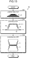
FIG. 13 is an explanatory diagram for explaining a method of shaping a girder member included in the composite material according to the second embodiment. -
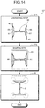
FIG. 14 is an explanatory diagram for explaining a method of shaping the composite material according to the second embodiment. -
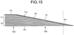
FIG. 15 is an explanatory diagram for explaining a finishing step of the composite material according to the second embodiment. - The following describes embodiments of the present invention in detail with reference to the drawings. The present invention is not limited to the embodiments. Components in the embodiments described below include a component that can be easily replaced by those skilled in the art, or substantially the same component. The components described below can be appropriately combined with each other. In a case in which there are a plurality of embodiments, the embodiments can be combined with each other.
- A
composite material 1 according to a first embodiment is, for example, as illustrated inFIG. 1 , a composite material constituting astructure 10 such as an airframe of an aircraft. Examples of thecomposite material 1 include a rib, a spar, and a stringer. - A material containing a reinforced fiber and resin with which the reinforced fiber is impregnated is an example of the
composite material 1. A bundle of several hundreds to several thousands of elementary fibers in a range from 5 µm to 7 µm is an example of the reinforced fiber. A carbon fiber is an example of the reinforced fiber. The reinforced fiber is not limited thereto, and may be other plastic fiber, glass fiber, or metallic fiber. The resin with which the reinforced fiber is impregnated is preferably a thermosetting resin, but may be a thermoplastic resin. An epoxy resin is an example of the thermosetting resin. Polyether ether ketone (PEEK), polyether ketone ketone (PEKK), polyphenylene sulfide (PPS), and the like are examples of the thermoplastic resin. However, the resin with which the reinforced fiber is impregnated is not limited thereto, and may be other resins. -
FIG. 1 is a perspective view schematically illustrating the structure in which the composite material according to the first embodiment is used.FIG. 2 is a perspective view illustrating the composite material according to the first embodiment.FIG. 3 is a cross-sectional view of the composite material according to the first embodiment.FIG. 4 is a cross-sectional view schematically illustrating a periphery of a flange portion of the composite material according to the first embodiment.FIG. 5 is an explanatory diagram illustrating respective members included in the composite material according to the first embodiment.FIG. 6 is an explanatory diagram for explaining a method of shaping a girder member included in the composite material according to the first embodiment.FIG. 7 is an explanatory diagram for explaining a method of shaping a cap member included in the composite material according to the first embodiment.FIG. 8 is an explanatory diagram for explaining a method of shaping the composite material according to the first embodiment.FIG. 9 is an explanatory diagram for explaining a finishing step of the composite material according to the first embodiment. - Before describing the
composite material 1, the following describes thestructure 10 in which thecomposite material 1 is used with reference toFIG. 1 . Thestructure 10 illustrated inFIG. 1 is a main plane of an aircraft, and includes askin 12, a stringer (not illustrated), spars 14, andribs 15. Thecomposite material 1 according to the first embodiment is, for example, applied to therib 15. In the first embodiment, thecomposite material 1 is applied to therib 15 disposed on theskin 12, but is not limited to therib 15. - The
skin 12 is an outer shell of the main plane, which is formed to extend in a span-wise direction. The stringer (not illustrated) is disposed on an inner surface of theskin 12. The stringer is formed in a T-shape, and disposed to extend in the span-wise direction along the inner surface of theskin 12 to reinforce theskin 12. Thespar 14 is a girder disposed to extend in the span-wise direction, which is disposed at a leading edge and a trailing edge of the main plane. Theribs 15 are disposed from the leading edge to the trailing edge of the main plane, and disposed side by side at predetermined intervals in the span-wise direction. - Next, the following describes the
composite material 1 with reference toFIG. 2 to FIG. 4 . Thecomposite material 1 is therib 15, which is joined to theskin 12 via an adhesive agent. Thecomposite material 1 is formed by laminating a plurality of fiber sheets each of which is obtained by making a reinforced fiber into a sheet shape, and is an I-shaped girder material including aweb portion 21 and fourflange portions 22 that are disposed at both end portions of theweb portion 21 and on both sides of the respective end portions of theweb portion 21. A load is applied to thecomposite material 1 in a direction in which theskin 12 and therib 15 are peeled off from each other (peeling direction). In the first embodiment, thecomposite material 1 is applied to the I-shaped girder material, but may be applied to a T-shaped girder material (for example, a stringer). Anycomposite material 1 including theflange portion 22 may be used. - The
web portion 21 is a portion like a flat plate, which is disposed so that a surface of the web portion 21 (a plate surface, that is, a web surface) protrudes in a direction (height direction) orthogonal to an adhesion target surface of theskin 12 that is an adhesion object, and disposed to extend in a length direction orthogonal to the height direction. In theweb portion 21, a plurality of fiber sheets are laminated in a width direction (laminating direction) that is orthogonal to the height direction and the length direction. - Among the four
flange portions 22, a pair offlange portions 22 disposed at one end portion of theweb portion 21 is disposed within a surface orthogonal to the height direction of theweb portion 21, and disposed to be opposed to the adhesion target surface of theskin 12. The pair offlange portions 22 is disposed on both sides in a direction (width direction) orthogonal to theweb portion 21 in the cross section illustrated inFIG. 2 andFIG. 3 . Each of theflange portions 22 is disposed to protrude from one end portion of theweb portion 21, as a base portion, toward a front end portion in a direction orthogonal to theweb portion 21. The same applies to the other pair offlange portions 22 disposed on the other end portion of theweb portion 21, and redundant description will not be repeated. - In each of the
flange portions 22, a surface to which the end portion of theweb portion 21 is connected is an inner surface P1, and a surface opposite to the inner surface P1 is an outer surface P2. The outer surface P2 of each of theflange portions 22 is an adhesion surface to adhere to the adhesion target surface of theskin 12. In each of theflange portions 22, a plurality of fiber sheets are laminated in the height direction (laminating direction). Each of theflange portions 22 includes aflat plate portion 22a on the base portion side and atapered portion 22b continuous to a front end side of theflat plate portion 22a in the width direction. Theflat plate portion 22a is a portion in which the inner surface P1 and the outer surface P2 of theflange portion 22 are parallel with each other, and the thickness thereof in the height direction (laminating direction) is uniform. The taperedportion 22b is formed such that the inner surface P1 is caused to be a tapered surface P3 that is sloped with respect to the outer surface P2 of theflange portion 22 so that the thickness is reduced toward the front end portion. - As illustrated in
FIG. 3 and FIG. 4 , thecomposite material 1 includes agirder member 25, twocap members 26, and twocore members 27. Thegirder member 25 is formed by joining a pair of flange laminates 31. One of the flange laminates 31 is disposed from theflange portion 22 on one side disposed on the other end portion side of the web portion 21 (for example, theflange portion 22 on upper right ofFIG. 3 ) to theflange portion 22 on one side disposed on one end portion side of the web portion 21 (for example, theflange portion 22 on lower right ofFIG. 3 ) via theweb portion 21. Similarly, theother flange laminate 31 is disposed from theflange portion 22 on the other side disposed on the other end portion side of the web portion 21 (for example, theflange portion 22 on upper left ofFIG. 3 ) to theflange portion 22 on the other side disposed on one end portion side of the web portion 21 (for example, theflange portion 22 on lower left ofFIG. 3 ) via theweb portion 21. A portion of the pair of flange laminates 31 (that is, the girder member 25) positioned at theweb portion 21, that is, a portion extending in the height direction constitutes theweb portion 21, and a portion thereof positioned at theflange portion 22, that is, a portion extending in the width direction is disposed on the inner surface side of theflange portion 22. - The two
cap members 26 are disposed on both sides of theweb portion 21 in the height direction respectively, and each of thecap members 26 is formed of acap laminate 32 disposed on the outer surface side of theflange portion 22. Thecap laminate 32 is disposed to extend between both sides in the width direction across theweb portion 21. A center portion in the width direction of thecap laminate 32 is formed as aflat plate portion 32a having a uniform thickness in the height direction (laminating direction), and taperedportions 32b are formed on both sides of theflat plate portion 32a in the width direction. The thickness of the taperedportion 32b in the laminating direction is reduced from the base portion of theflange portion 22 toward the front end portion. - Each of the flange laminates 31 includes a covering
portion 31a that covers the taperedportion 32b of thecap laminate 32. Thus, the taperedportion 22b of theflange portion 22 is formed by laminating the coveringportion 31a of theflange laminate 31 on the taperedportion 32b of thecap laminate 32. A fiber sheet on the outermost surface (innermost surface) of theflange laminate 31 is an outermostsurface fiber sheet 35. - The
core member 27 fills a gap that is formed when thegirder member 25 and thecap member 26 are combined with each other, and functions as a core material. Thecore member 27 is disposed over the length direction. - Next, the following describes a method of shaping the
composite material 1 according to the first embodiment with reference toFIG. 5 to FIG. 9 . In this shaping method, as illustrated inFIG. 5 , thegirder member 25, the twocap members 26, and the twocore members 27 are shaped separately, and they are combined with each other to form thecomposite material 1 illustrated inFIG. 2 andFIG. 3 . Specifically, the method of shaping thecomposite material 1 includes a girder member shaping step S1 illustrated inFIG. 6 for shaping thegirder member 25, a cap member shaping step S2 illustrated inFIG. 7 for shaping thecap member 26, a core member shaping step for shaping thecore member 27, a composite material shaping step S3 illustrated inFIG. 8 for shaping thecomposite material 1 by combining thegirder member 25, thecap member 26, and thecore member 27, and a finishing step S4 illustrated inFIG. 8 andFIG. 9 for finishing thecomposite material 1. - As illustrated in
FIG. 6 , at the girder member shaping step S1, first, a plurality of fiber sheets having the same length in the width direction are laminated to form a laminate 41 (laminating step S11). Subsequently, the formedlaminate 41 is disposed on a male shaping die 42, abagging film 43 is disposed to cover the laminate 41, the inside of thebagging film 43 is vacuumed, and pressurization and heating are performed to shape the flange laminate 31 (shaping step S12). At the shaping step S12, a pair of flange laminates 31 is shaped. The pair of shaped flange laminates 31 is assembled back to back to form thegirder member 25 such that portions thereof extending in the length direction are combined with each other, and portions thereof extending in the width direction are caused to spread toward both sides in the width direction (assembling step S13). - As illustrated in
FIG. 7 , at the cap member shaping step S2, a plurality of fiber sheets are laminated to form thecap laminate 32 as thecap member 26 so that the length in the width direction is reduced from one side in the laminating direction (lower side/outer surface side) toward the other side (upper side/inner surface side) (laminating step S21). That is, at the laminating step S21, a plurality of fiber sheets are laminated to form thecap laminate 32 such that theflat plate portion 32a and thetapered portions 32b disposed on both sides of theflat plate portion 32a are formed. At the laminating step S21, twocap laminates 32 are shaped. - Although not illustrated, at the core member shaping step, shaped is the
core member 27 having substantially the same shape as that of the gap formed by thegirder member 25 and thecap member 26. Thecore member 27 may be formed by winding the fiber sheet by pultrusion, or may be formed by bundling reinforced fibers. The method of forming thecore member 27 is not limited. At the core member shaping step, twocore members 27 are shaped. - As illustrated in
FIG. 8 , at the composite material shaping step S3, the shapedgirder member 25, the twocap members 26, and the twocore members 27 are combined so that theflange laminate 31 and thecap laminate 32 are laminated (laminating step S31). At the laminating step S31, thecap members 26 and thecore members 27 may be disposed in a state in which theflange laminate 31 is fitted to the shaping die 42. At the laminating step S31, thegirder member 25 and thecap member 26 are combined so that the coveringportions 31a of both of the flange laminates 31 of thegirder member 25 cover both of the taperedportions 32b of thecap member 26. Subsequently, the baggingfilm 43 is disposed to cover the respective combinedmembers bagging film 43 is vacuumed, and pressurization and heating are performed to shape the composite material 1 (shaping step S32). At this point, at the shaping step S32, aplate 44 is disposed on an outer surface side of thecap member 26, and theplate 44 shapes theflange portion 22 to cause the outer surface of theflange portion 22 to have a required shape at the time of shaping. An unnecessary portion of the shapedcomposite material 1 is cut off by trimming (finishing step S4). - As illustrated in
FIG. 9 , the unnecessary portion cut off at the finishing step S4 is the front end portion of each of theflange portions 22 of theflange laminate 31. The front end portion of each of theflange portions 22 is cut off along the outer surface P2 at a predetermined length in the width direction. Thus, a cut-off surface P4 is formed at theflange portion 22 of thecomposite material 1 after the finishing step S4, the cut-off surface P4 formed by cutting off the front end portion of the tapered surface P3. The cut-off surface P4 is a surface orthogonal to the width direction, and orthogonal to the outer surface P2 of theflange portion 22. A sealing material illustrated inFIG. 4 is disposed on the cut-off surface P4 at the time when thecomposite material 1 adheres to theskin 12. - As described above, according to the first embodiment, by forming the tapered surface P3 on the
flange portion 22, even when a load is applied to thecomposite material 1 in at least one of the shearing direction and the peeling direction, the load can be distributed by the tapered surface P3. Thus, peak stress can be prevented from being generated at the front end portion of theflange portion 22, and detachment from theskin 12 caused by the load in the shearing direction and the peeling direction can be prevented. The tapered surface P3 of the front end portion of theflange portion 22 can be covered with theflange laminate 31 including the outermostsurface fiber sheet 35, so that the fiber sheet can be prevented from being exposed at the front end portion of theflange portion 22, and a spark can be prevented from being generated due to lightning and the like. - According to the first embodiment, the tapered
portion 32b of thecap laminate 32 can be covered with the coveringportion 31a of theflange laminate 31, so that a layer thickness of the fiber sheet can be increased on the tapered surface P3 side of theflange portion 22, and a spark can be more preferably prevented from being generated due to lightning and the like. - According to the first embodiment, by cutting off the front end portion of the tapered surface P3 of the
flange portion 22, the tapered surface P3 can be prevented from being damaged due to physical contact. - According to the first embodiment, by combining the
girder member 25, thecap member 26, and thecore member 27 to be shaped, the taperedportion 32b of thecap laminate 32 is covered with theflange laminate 31, so that thecomposite material 1 having the tapered surface P3 formed on theflange portion 22 can be shaped efficiently and appropriately. - According to the first embodiment, by performing the finishing step S4, the
composite material 1 having an appropriate shape from which the unnecessary portion is cut off can be formed. - Next, the following describes a
composite material 51 according to a second embodiment with reference toFIG. 10 to FIG. 15 . To avoid redundant description, a portion different from that of the first embodiment will be described in the second embodiment. A portion having the same configuration as that of the first embodiment is denoted by the same reference numeral.FIG. 10 is a cross-sectional view of the composite material according to the second embodiment.FIG. 11 is a cross-sectional view schematically illustrating a periphery of a flange portion of the composite material according to the second embodiment.FIG. 12 is an explanatory diagram illustrating respective members included in the composite material according to the second embodiment.FIG. 13 is an explanatory diagram for explaining a method of shaping a girder member included in the composite material according to the second embodiment.FIG. 14 is an explanatory diagram for explaining a method of shaping the composite material according to the second embodiment.FIG. 15 is an explanatory diagram for explaining a finishing step of the composite material according to the second embodiment. - Similarly to the first embodiment, the
composite material 51 according to the second embodiment is an I-shaped girder material including theweb portion 21 and the fourflange portions 22. As illustrated inFIG. 10 andFIG. 11 , thecomposite material 51 includes agirder member 65, twocap members 66, and twocore members 67. Thegirder member 65 is formed by joining a pair of flange laminates 71. One of the flange laminates 71 is disposed from theflange portion 22 on one side disposed on the other end portion side of the web portion 21 (for example, theflange portion 22 on upper right ofFIG. 10 ) to theflange portion 22 on one side disposed on one end portion side of the web portion 21 (for example, theflange portion 22 on lower right ofFIG. 10 ) via theweb portion 21. Similarly, theother flange laminate 71 is disposed from theflange portion 22 on the other side disposed on the other end portion side of the web portion 21 (for example, theflange portion 22 on upper left ofFIG. 10 ) to theflange portion 22 on the other side disposed on one end portion side of the web portion 21 (for example, theflange portion 22 on lower left ofFIG. 10 ) via theweb portion 21. A portion of the pair of flange laminates 71 (that is, the girder member 25) positioned at theweb portion 21, that is, a portion extending in the height direction constitutes theweb portion 21, and a portion thereof positioned at theflange portion 22, that is, a portion extending in the width direction is an inner surface side taperedportion 71a disposed on the inner surface side of theflange portion 22. Each of the flange laminates 71 includes an outermostsurface fiber sheet 75 serving as a fiber sheet on the outermost surface that covers the inner surface side taperedportion 71a. - The two
cap members 66 are disposed on both sides of theweb portion 21 in the height direction respectively, and each of thecap members 66 is formed of acap laminate 72 disposed on the outer surface side of theflange portion 22. Thecap laminate 72 is disposed to extend between both sides in the width direction across theweb portion 21. A center portion in the width direction of thecap laminate 72 is formed as aflat plate portion 72a having a uniform thickness in the height direction (laminating direction), and outer surface side taperedportions 72b are formed on both sides of theflat plate portion 72a in the width direction. The thickness of the outer surface side taperedportion 72b in the laminating direction is reduced from the base portion of theflange portion 22 toward the front end portion. The outer surface side taperedportion 72b is disposed to be continuous to the inner surface side taperedportion 71a of theflange laminate 71, so that the thickness of the inner surface side taperedportion 71a and the outer surface side taperedportion 72b in the laminating direction is continuously reduced from the base portion of theflange portion 22 toward the front end portion. - The outermost
surface fiber sheet 75 of each of the flange laminates 71 covers the inner surface side taperedportion 71a and the outer surface side taperedportion 72b. Thus, the taperedportion 22b of theflange portion 22 is formed by laminating the outermostsurface fiber sheet 75 on the inner surface side taperedportion 71a of theflange laminate 71 and the outer surface side taperedportion 72b of thecap laminate 72. Thecore member 67 is the same as thecore member 27 in the first embodiment, so that redundant description will not be repeated. - Next, the following describes the method of shaping the
composite material 51 according to the second embodiment with reference toFIG. 12 to FIG. 15 . In this shaping method, as illustrated inFIG. 12 , thegirder member 65, the twocap members 66, and the twocore members 67 are shaped separately, and they are combined with each other to form thecomposite material 51 illustrated inFIG. 10 . Specifically, the method of shaping thecomposite material 51 includes a girder member shaping step S6 illustrated inFIG. 13 for shaping thegirder member 65, a cap member shaping step for shaping thecap member 66, a core member shaping step for shaping thecore member 67, a composite material shaping step S7 illustrated inFIG. 14 for shaping thecomposite material 51 by combining thegirder member 65, thecap member 66, and thecore member 67, and a finishing step S8 illustrated inFIG. 14 andFIG. 15 for finishing thecomposite material 51. - As illustrated in
FIG. 13 , at the girder member shaping step S6, first, a plurality of fiber sheets are laminated to form a laminate 81 so that the length thereof in the width direction is reduced from one side in the laminating direction (lower side/outer surface side) toward the other side (upper side/inner surface side) (laminating step S61). Subsequently, before disposing the formedlaminate 81 on the male shaping die 42, the fiber sheet to be the outermostsurface fiber sheet 75 is disposed on the shaping die 42. Thereafter, the inner surface side of the laminate 81 is caused to be opposed to the outermostsurface fiber sheet 75, and the laminate 81 is disposed on the outermostsurface fiber sheet 75. The baggingfilm 43 is then disposed to cover the laminate 81 and the outermostsurface fiber sheet 75, the inside of thebagging film 43 is vacuumed, and pressurization and heating are performed to shape the flange laminate 71 (shaping step S62). A pair of flange laminates 71 is shaped at the shaping step S62. The pair of shaped flange laminates 71 is assembled back to back to form thegirder member 65 such that portions thereof extending in the length direction are combined with each other, and portions thereof extending in the width direction are caused to spread toward both sides in the width direction (assembling step S63). - Although not illustrated, at the cap member shaping step, similarly to the cap member shaping step S2 in the first embodiment illustrated in
FIG. 7 , a plurality of fiber sheets are laminated to form thecap laminate 72 as thecap member 66 so that the length in the width direction is reduced from one side in the laminating direction (lower side/outer surface side) toward the other side (upper side/inner surface side). That is, at the cap member shaping step, a plurality of fiber sheets are laminated to form thecap laminate 72 such that theflat plate portion 72a and the outer surface side taperedportions 72b disposed on both sides of theflat plate portion 72a are formed. Twocap laminates 72 are shaped at the cap member shaping step. The core member shaping step is the same as the core member shaping step in the first embodiment, so that redundant description will not be repeated. - As illustrated in
FIG. 14 , at the composite material shaping step S7, the shapedgirder member 65, the twocap members 66, and the twocore members 67 are combined so that the outermostsurface fiber sheet 75, theflange laminate 71, and thecap laminate 72 are laminated (laminating step S71). At the laminating step S71, similarly to the first embodiment, thecap members 66 and thecore members 67 may be disposed in a state in which theflange laminate 71 is fitted to the shaping die 42. At the laminating step S71, thegirder member 65 and thecap member 66 are combined so that outermostsurface fiber sheets 75 of both of the flange laminates 71 of thegirder member 65 cover both of the outer surface side taperedportions 72b of thecap members 66. Subsequently, the baggingfilm 43 is disposed to cover the respective combinedmembers bagging film 43 is vacuumed, and pressurization and heating are performed to shape the composite material 51 (shaping step S72). At this point, at the shaping step S72, theplate 44 is disposed on the outer surface side of thecap member 66 similarly to the first embodiment, and theplate 44 shapes theflange portion 22 to cause the outer surface of theflange portion 22 to have a required shape at the time of shaping. An unnecessary portion of the shapedcomposite material 51 is cut off by trimming (finishing step S8). - As illustrated in
FIG. 15 , the unnecessary portion cut off at the finishing step S8 is the front end portion of each of theflange portions 22 at the outermostsurface fiber sheet 75 of theflange laminate 71, and the front end portion of each of the outer surface side taperedportions 72b of thecap laminate 72. The front end portion of each of theflange portions 22 is cut off at a predetermined length in the width direction. Thus, similarly to the first embodiment, a cut-off surface P4 is formed at theflange portion 22 of thecomposite material 51 after the finishing step S8, the cut-off surface P4 formed by cutting off the front end portion of the tapered surface P3. The cut-off surface P4 is a surface orthogonal to the width direction, and orthogonal to the outer surface P2 of theflange portion 22. A sealing material illustrated inFIG. 11 is disposed on the cut-off surface P4 at the time when thecomposite material 51 adheres to theskin 12. - As described above, according to the second embodiment, by forming the tapered surface P3 on the
flange portion 22, even when a load is applied to thecomposite material 51 in at least one of the shearing direction and the peeling direction, the load can be distributed by the tapered surface P3. Thus, peak stress can be prevented from being generated at the front end portion of theflange portion 22, and detachment from theskin 12 caused by the load in the shearing direction and the peeling direction can be prevented. The tapered surface P3 of the front end portion of theflange portion 22 can be covered with the outermostsurface fiber sheet 75, so that the fiber sheet can be prevented from being exposed at the front end portion of theflange portion 22, and a spark can be prevented from being generated due to lightning and the like. - According to the second embodiment, the fiber sheet disposed along the tapered surface P3 is only the outermost
surface fiber sheet 75, so that the unnecessary portion to be cut off can be reduced at the finishing step S8 for cutting off (trimming) the unnecessary portion of thecomposite material 51 after shaping. Due to this, thecomposite material 51 can be easily manufactured, and efficiency can be improved. - According to the second embodiment, by combining the
girder member 65, thecap member 66, and thecore member 67 to be shaped, the outer surface side taperedportion 72b of thecap laminate 72 and the inner surface side taperedportion 71a of theflange laminate 71 are covered with the outermostsurface fiber sheet 75, so that thecomposite material 51 having the tapered surface P3 formed on theflange portion 22 can be shaped efficiently and appropriately. -
- 1 Composite material
- 10 Structure
- 12 Skin
- 14 Spar
- 15 Rib
- 21 Web portion
- 22 Flange portion
- 22a Flat plate portion
- 22b Tapered portion
- 25 Girder member
- 26 Cap member
- 27 Core member
- 31 Flange laminate
- 31a Covering portion
- 32 Cap laminate
- 32a Flat plate portion
- 32b Tapered portion
- 35 Outermost surface fiber sheet
- 41 Laminate
- 42 Shaping die
- 43 Bagging film
- 44 Plate
- 51 Composite material (second embodiment)
- 65 Girder member (second embodiment)
- 66 Cap member (second embodiment)
- 67 Core member (second embodiment)
- 71 Flange laminate (second embodiment)
- 71a Inner surface side tapered portion (second embodiment)
- 72 Cap laminate (second embodiment)
- 72a Flat plate portion (second embodiment)
- 72b Outer surface side tapered portion (second embodiment)
- 75 Outermost surface fiber sheet (second embodiment)
- P1 Inner surface
- P2 Outer surface
- P3 Tapered surface
- P4 Cut-off surface
Claims (7)
- A composite material comprising:a web portion; anda flange portion disposed at an end portion of the web portion, whereinthe flange portion is formed from a plurality of fiber sheets laminated and has a surface on one side in a laminating direction of the flange portion serving as an inner surface to which the end portion of the web portion is connected and a surface on the other side in the laminating direction of the flange portion serving as an outer surface,the inner surface of the flange portion has a tapered surface having a thickness that is reduced from a base portion to which the end portion of the web portion is connected toward a front end portion in the laminating direction, andthe flange portion includes an outermost surface fiber sheet disposed on the tapered surface, the outermost surface fiber sheet serving as the fiber sheet on an outermost surface that covers the tapered surface.
- The composite material according to claim 1, wherein the flange portion includesa flange laminate that is the plurality of fiber sheets laminated disposed on the inner surface side, anda cap laminate that is the plurality of fiber sheets laminated disposed on the outer surface side,the cap laminate includes a tapered portion having a thickness that is reduced from the base portion of the flange portion toward the front end portion in the laminating direction,
the flange laminate is disposed to cover the tapered portion, and
the fiber sheet on the outermost surface of the flange laminate is the outermost surface fiber sheet. - The composite material according to claim 1, wherein
the flange portion includesa flange laminate that is the plurality of fiber sheets laminated disposed on the inner surface side, anda cap laminate that is the plurality of fiber sheets laminated disposed on the outer surface side,the cap laminate includes an outer surface side tapered portion having a thickness that is reduced from the base portion of the flange portion toward the front end portion in the laminating direction, and
the flange laminate includesan inner surface side tapered portion continuous to the outer surface side tapered portion, the inner surface side tapered portion having a thickness that is reduced from the base portion of the flange portion toward the front end portion in the laminating direction, andthe outermost surface fiber sheet serving as the fiber sheet on the outermost surface that covers the outer surface side tapered portion and the inner surface side tapered portion. - The composite material according to any one of claims 1 to 3, wherein the flange portion has a cut-off surface formed by cutting off the front end portion of the tapered surface.
- A method of shaping a composite material that comprises a web portion and a pair of flange portions that are disposed at an end portion of the web portion and disposed on both sides of the web portion, whereineach of the flange portions of the pair is formed from a plurality of fiber sheets laminated and has a surface on one side in a laminating direction of the flange portion serving as an inner surface to which the end portion of the web portion is connected and a surface on the other side in the laminating direction of the flange portion serving as an outer surface,the inner surface of the flange portion has a tapered surface having a thickness that is reduced from a base portion to which the end portion of the web portion is connected toward a front end portion in the laminating direction,the composite material includesone flange laminate disposed from the web portion to the inner surface side of one of the flange portions,another flange laminate disposed from the web portion to the inner surface side of the other one of the flange portions, anda cap laminate disposed on the outer surface side of the pair of flange portions,the cap laminate includes a pair of tapered portions having a thickness that is reduced from the base portion of the flange portion toward a front end portion in the laminating direction,the one flange laminate covers one of the tapered portions of the cap laminate,the other flange laminate covers the other one of the tapered portions of the cap laminate, andthe method comprises:a girder member shaping step of shaping the one flange laminate and the other flange laminate by laminating the fiber sheets, and shaping a girder member including the web portion and portion of the pair of flange portions by combining the one flange laminate and the other flange laminate that have been shaped;a cap member shaping step of shaping the cap laminate as a cap member by laminating the fiber sheets; anda composite material shaping step of shaping the composite material by combining the girder member and the cap member so that both of the flange laminates of the girder member cover both of the tapered portions of the cap member.
- A method of shaping a composite material that comprises a web portion and a pair of flange portions that are disposed at an end portion of the web portion and disposed on both sides of the web portion, wherein
each of the flange portions of the pair is formed from a plurality of fiber sheets laminated and has a surface on one side in a laminating direction of the flange portion serving as an inner surface to which the end portion of the web portion is connected and a surface on the other side in the laminating direction of the flange portion serving as an outer surface,
the inner surface of the flange portion has a tapered surface having a thickness that is reduced from a base portion to which the end portion of the web portion is connected toward a front end portion in the laminating direction,
the composite material includesone flange laminate disposed from the web portion to the inner surface side of one of the flange portions,another flange laminate disposed from the web portion to the inner surface side of the other one of the flange portions, anda cap laminate disposed on the outer surface side of the pair of flange portions,the cap laminate includes a pair of outer surface side tapered portions having a thickness that is reduced from the base portion of the flange portion toward a front end portion in the laminating direction,
the one flange laminate includesone inner surface side tapered portion continuous to one of the outer surface side tapered portions, the one inner surface side tapered portion having a thickness that is reduced from the base portion of the flange portion toward a front end portion on one side in the laminating direction, andone outermost surface fiber sheet serving as the fiber sheet on the outermost surface that covers the one of the outer surface side tapered portions and the one inner surface side tapered portion,the other flange laminate includesanother inner surface side tapered portion continuous to the other one of the outer surface side tapered portions, the other inner surface side tapered portion having a thickness that is reduced from the base portion of the flange portion toward a front end portion on the other side in the laminating direction, andanother outermost surface fiber sheet serving as the fiber sheet on the outermost surface that covers the other one of the outer surface side tapered portions and the other inner surface side tapered portion, andthe method comprises:a girder member shaping step of shaping the one flange laminate and the other flange laminate by laminating the fiber sheets, and shaping a girder member including the web portion and portion of the pair of flange portions by combining the one flange laminate and the other flange laminate that have been shaped;a cap laminate shaping step of shaping the cap laminate as a cap member by laminating the fiber sheets; anda composite material shaping step of shaping the composite material by combining the girder member and the cap member so that both of the outermost surface fiber sheets of the girder member cover both of the inner surface side tapered portions of the girder member and both of the outer surface side tapered portions of the cap member. - The method of shaping the composite material according to claim 5 or 6, further comprising cutting off an unnecessary portion of the composite material to be finished after the composite material shaping step.
Applications Claiming Priority (2)
| Application Number | Priority Date | Filing Date | Title |
|---|---|---|---|
| JP2016228322A JP6949474B2 (en) | 2016-11-24 | 2016-11-24 | Composite material and method of molding composite material |
| PCT/JP2017/040393 WO2018096933A1 (en) | 2016-11-24 | 2017-11-09 | Composite member and method of forming composite member |
Publications (3)
| Publication Number | Publication Date |
|---|---|
| EP3495120A1 true EP3495120A1 (en) | 2019-06-12 |
| EP3495120A4 EP3495120A4 (en) | 2019-09-18 |
| EP3495120B1 EP3495120B1 (en) | 2020-09-09 |
Family
ID=62195800
Family Applications (1)
| Application Number | Title | Priority Date | Filing Date |
|---|---|---|---|
| EP17873319.2A Active EP3495120B1 (en) | 2016-11-24 | 2017-11-09 | Composite member and method of forming composite member |
Country Status (5)
| Country | Link |
|---|---|
| US (1) | US20210276300A1 (en) |
| EP (1) | EP3495120B1 (en) |
| JP (1) | JP6949474B2 (en) |
| CN (1) | CN109641403B (en) |
| WO (1) | WO2018096933A1 (en) |
Families Citing this family (4)
| Publication number | Priority date | Publication date | Assignee | Title |
|---|---|---|---|---|
| CA3033583C (en) * | 2018-03-06 | 2023-08-15 | The Boeing Company | Stringer stiffened composite panels having improved pull-off strength |
| US11325688B2 (en) * | 2019-05-09 | 2022-05-10 | The Boeing Company | Composite stringer and methods for forming a composite stringer |
| US11383820B2 (en) * | 2019-06-11 | 2022-07-12 | The Boeing Company | Aerodynamic surface lap splice |
| KR102790832B1 (en) * | 2020-03-18 | 2025-04-03 | 더 보드 어브 트러스티스 어브 더 리랜드 스탠포드 주니어 유니버시티 | Finite-size composite laminate card, tapered composite laminate structure formed therefrom, and method of making and using the same |
Family Cites Families (8)
| Publication number | Priority date | Publication date | Assignee | Title |
|---|---|---|---|---|
| US4331723A (en) * | 1980-11-05 | 1982-05-25 | The Boeing Company | Advanced composite |
| JP2517634B2 (en) * | 1987-12-21 | 1996-07-24 | 富士重工業株式会社 | Method of molding composite material products |
| US6217000B1 (en) * | 1996-10-25 | 2001-04-17 | The Boeing Company | Composite fabrication method and tooling to improve part consolidation |
| AU6354499A (en) * | 1998-10-23 | 2000-05-15 | Bae Systems Plc | A roll forming machine and method |
| US6889937B2 (en) * | 1999-11-18 | 2005-05-10 | Rocky Mountain Composites, Inc. | Single piece co-cure composite wing |
| WO2008090911A1 (en) * | 2007-01-26 | 2008-07-31 | Toray Industries, Inc. | Preform for molding fiber-reinforced resin beam, process for producing the same, apparatus for producing the same, and process for producing fiber-reinforced resin beam |
| GB0912015D0 (en) * | 2009-07-10 | 2009-08-19 | Airbus Operations Ltd | Stringer |
| US20150217850A1 (en) * | 2014-02-06 | 2015-08-06 | The Boeing Company | Laminated i-blade stringer |
-
2016
- 2016-11-24 JP JP2016228322A patent/JP6949474B2/en active Active
-
2017
- 2017-11-09 US US16/330,523 patent/US20210276300A1/en not_active Abandoned
- 2017-11-09 WO PCT/JP2017/040393 patent/WO2018096933A1/en not_active Ceased
- 2017-11-09 EP EP17873319.2A patent/EP3495120B1/en active Active
- 2017-11-09 CN CN201780052719.1A patent/CN109641403B/en not_active Expired - Fee Related
Also Published As
| Publication number | Publication date |
|---|---|
| CN109641403A (en) | 2019-04-16 |
| JP2018083362A (en) | 2018-05-31 |
| JP6949474B2 (en) | 2021-10-13 |
| US20210276300A1 (en) | 2021-09-09 |
| EP3495120A4 (en) | 2019-09-18 |
| CN109641403B (en) | 2021-04-13 |
| WO2018096933A1 (en) | 2018-05-31 |
| EP3495120B1 (en) | 2020-09-09 |
Similar Documents
| Publication | Publication Date | Title |
|---|---|---|
| US8114329B2 (en) | Wing and blade structure using pultruded composites | |
| RU2514747C2 (en) | Reinforced stiffness elements and methods of their production | |
| EP3495120B1 (en) | Composite member and method of forming composite member | |
| EP2907652B1 (en) | Composite filler | |
| EP3138769B1 (en) | Radius filler containing vertical ply stacks and thin plies | |
| US9701391B2 (en) | Aircraft structure comprising a skin panel | |
| EP2689918B1 (en) | Laminated composite bending and stiffening members with reinforcement by inter-laminar metal sheets | |
| EP2318466B1 (en) | Method for manufacturing a composite structure and intermediate composite structure | |
| US20130139961A1 (en) | Dual-skin structures | |
| KR20150034827A (en) | Bonded composite airfoil and fabrication method | |
| US20090121081A1 (en) | Composite Bulkhead and Skin Construction | |
| US20150239200A1 (en) | Composite sandwich panel with differential resin layers | |
| US11279119B2 (en) | Pre-filled radius layups | |
| EP2556947B1 (en) | Vertical laminate noodle for high capacity pull-off for a composite stringer | |
| JP2014097786A (en) | Joint for composite wings | |
| KR20140045372A (en) | Method and device for transporting, placing and compacting composite stiffeners | |
| CN106167088A (en) | Multiple wing beam type torsion box structure | |
| CN112512784B (en) | Wind turbine blade spar structure and method of manufacturing the same | |
| US9718262B2 (en) | Roll forming composite components | |
| EP4119334B1 (en) | Composite material structure and manufacturing method of composite material structure | |
| EP2522495A1 (en) | Structural member with flange having a clean cut edge, and process for the manufacture thereof | |
| US8257536B2 (en) | Automated elongate insert wrapping system | |
| US11752704B2 (en) | Composite laminate for an airframe lifting surface and method for manufacturing thereof | |
| EP3584150A1 (en) | Method for manufacturing a rear section of an aircraft and aircraft rear section manufactured by said method | |
| EP4467328B1 (en) | Method for manufacturing spars or ribs for aircrafts |
Legal Events
| Date | Code | Title | Description |
|---|---|---|---|
| STAA | Information on the status of an ep patent application or granted ep patent |
Free format text: STATUS: THE INTERNATIONAL PUBLICATION HAS BEEN MADE |
|
| PUAI | Public reference made under article 153(3) epc to a published international application that has entered the european phase |
Free format text: ORIGINAL CODE: 0009012 |
|
| STAA | Information on the status of an ep patent application or granted ep patent |
Free format text: STATUS: REQUEST FOR EXAMINATION WAS MADE |
|
| 17P | Request for examination filed |
Effective date: 20190308 |
|
| AK | Designated contracting states |
Kind code of ref document: A1 Designated state(s): AL AT BE BG CH CY CZ DE DK EE ES FI FR GB GR HR HU IE IS IT LI LT LU LV MC MK MT NL NO PL PT RO RS SE SI SK SM TR |
|
| AX | Request for extension of the european patent |
Extension state: BA ME |
|
| A4 | Supplementary search report drawn up and despatched |
Effective date: 20190816 |
|
| RIC1 | Information provided on ipc code assigned before grant |
Ipc: B64C 1/06 20060101ALI20190809BHEP Ipc: B29C 70/54 20060101ALI20190809BHEP Ipc: B29K 105/08 20060101ALI20190809BHEP Ipc: B29D 99/00 20100101ALI20190809BHEP Ipc: B64C 1/00 20060101ALI20190809BHEP Ipc: B29C 70/02 20060101AFI20190809BHEP Ipc: B29L 31/30 20060101ALI20190809BHEP |
|
| DAV | Request for validation of the european patent (deleted) | ||
| DAX | Request for extension of the european patent (deleted) | ||
| GRAP | Despatch of communication of intention to grant a patent |
Free format text: ORIGINAL CODE: EPIDOSNIGR1 |
|
| STAA | Information on the status of an ep patent application or granted ep patent |
Free format text: STATUS: GRANT OF PATENT IS INTENDED |
|
| RIC1 | Information provided on ipc code assigned before grant |
Ipc: B32B 5/26 20060101ALI20200525BHEP Ipc: B29C 70/54 20060101ALI20200525BHEP Ipc: B29D 99/00 20100101ALI20200525BHEP Ipc: B29L 31/30 20060101ALI20200525BHEP Ipc: B64C 1/06 20060101ALI20200525BHEP Ipc: B29C 70/02 20060101AFI20200525BHEP Ipc: B64C 1/00 20060101ALI20200525BHEP Ipc: B29K 105/08 20060101ALI20200525BHEP |
|
| INTG | Intention to grant announced |
Effective date: 20200618 |
|
| RIN1 | Information on inventor provided before grant (corrected) |
Inventor name: ENOKIDA, TOSHIAKI Inventor name: ISHIDA, JUN Inventor name: YOSHINO, KATSUYA Inventor name: KATO, TETSUYA Inventor name: YAMAZAKI, TOSHIYUKI Inventor name: ABE, TOSHIO Inventor name: KAMO, SOTA Inventor name: TAKAGI, KIYOKA |
|
| GRAS | Grant fee paid |
Free format text: ORIGINAL CODE: EPIDOSNIGR3 |
|
| GRAA | (expected) grant |
Free format text: ORIGINAL CODE: 0009210 |
|
| STAA | Information on the status of an ep patent application or granted ep patent |
Free format text: STATUS: THE PATENT HAS BEEN GRANTED |
|
| AK | Designated contracting states |
Kind code of ref document: B1 Designated state(s): AL AT BE BG CH CY CZ DE DK EE ES FI FR GB GR HR HU IE IS IT LI LT LU LV MC MK MT NL NO PL PT RO RS SE SI SK SM TR |
|
| REG | Reference to a national code |
Ref country code: GB Ref legal event code: FG4D |
|
| REG | Reference to a national code |
Ref country code: AT Ref legal event code: REF Ref document number: 1311049 Country of ref document: AT Kind code of ref document: T Effective date: 20200915 Ref country code: CH Ref legal event code: EP |
|
| REG | Reference to a national code |
Ref country code: IE Ref legal event code: FG4D |
|
| REG | Reference to a national code |
Ref country code: DE Ref legal event code: R096 Ref document number: 602017023552 Country of ref document: DE |
|
| REG | Reference to a national code |
Ref country code: LT Ref legal event code: MG4D |
|
| PG25 | Lapsed in a contracting state [announced via postgrant information from national office to epo] |
Ref country code: HR Free format text: LAPSE BECAUSE OF FAILURE TO SUBMIT A TRANSLATION OF THE DESCRIPTION OR TO PAY THE FEE WITHIN THE PRESCRIBED TIME-LIMIT Effective date: 20200909 Ref country code: FI Free format text: LAPSE BECAUSE OF FAILURE TO SUBMIT A TRANSLATION OF THE DESCRIPTION OR TO PAY THE FEE WITHIN THE PRESCRIBED TIME-LIMIT Effective date: 20200909 Ref country code: NO Free format text: LAPSE BECAUSE OF FAILURE TO SUBMIT A TRANSLATION OF THE DESCRIPTION OR TO PAY THE FEE WITHIN THE PRESCRIBED TIME-LIMIT Effective date: 20201209 Ref country code: SE Free format text: LAPSE BECAUSE OF FAILURE TO SUBMIT A TRANSLATION OF THE DESCRIPTION OR TO PAY THE FEE WITHIN THE PRESCRIBED TIME-LIMIT Effective date: 20200909 Ref country code: BG Free format text: LAPSE BECAUSE OF FAILURE TO SUBMIT A TRANSLATION OF THE DESCRIPTION OR TO PAY THE FEE WITHIN THE PRESCRIBED TIME-LIMIT Effective date: 20201209 Ref country code: LT Free format text: LAPSE BECAUSE OF FAILURE TO SUBMIT A TRANSLATION OF THE DESCRIPTION OR TO PAY THE FEE WITHIN THE PRESCRIBED TIME-LIMIT Effective date: 20200909 Ref country code: GR Free format text: LAPSE BECAUSE OF FAILURE TO SUBMIT A TRANSLATION OF THE DESCRIPTION OR TO PAY THE FEE WITHIN THE PRESCRIBED TIME-LIMIT Effective date: 20201210 |
|
| REG | Reference to a national code |
Ref country code: AT Ref legal event code: MK05 Ref document number: 1311049 Country of ref document: AT Kind code of ref document: T Effective date: 20200909 |
|
| REG | Reference to a national code |
Ref country code: NL Ref legal event code: MP Effective date: 20200909 |
|
| PG25 | Lapsed in a contracting state [announced via postgrant information from national office to epo] |
Ref country code: LV Free format text: LAPSE BECAUSE OF FAILURE TO SUBMIT A TRANSLATION OF THE DESCRIPTION OR TO PAY THE FEE WITHIN THE PRESCRIBED TIME-LIMIT Effective date: 20200909 Ref country code: PL Free format text: LAPSE BECAUSE OF FAILURE TO SUBMIT A TRANSLATION OF THE DESCRIPTION OR TO PAY THE FEE WITHIN THE PRESCRIBED TIME-LIMIT Effective date: 20200909 Ref country code: RS Free format text: LAPSE BECAUSE OF FAILURE TO SUBMIT A TRANSLATION OF THE DESCRIPTION OR TO PAY THE FEE WITHIN THE PRESCRIBED TIME-LIMIT Effective date: 20200909 |
|
| PG25 | Lapsed in a contracting state [announced via postgrant information from national office to epo] |
Ref country code: EE Free format text: LAPSE BECAUSE OF FAILURE TO SUBMIT A TRANSLATION OF THE DESCRIPTION OR TO PAY THE FEE WITHIN THE PRESCRIBED TIME-LIMIT Effective date: 20200909 Ref country code: PT Free format text: LAPSE BECAUSE OF FAILURE TO SUBMIT A TRANSLATION OF THE DESCRIPTION OR TO PAY THE FEE WITHIN THE PRESCRIBED TIME-LIMIT Effective date: 20210111 Ref country code: RO Free format text: LAPSE BECAUSE OF FAILURE TO SUBMIT A TRANSLATION OF THE DESCRIPTION OR TO PAY THE FEE WITHIN THE PRESCRIBED TIME-LIMIT Effective date: 20200909 Ref country code: CZ Free format text: LAPSE BECAUSE OF FAILURE TO SUBMIT A TRANSLATION OF THE DESCRIPTION OR TO PAY THE FEE WITHIN THE PRESCRIBED TIME-LIMIT Effective date: 20200909 Ref country code: SM Free format text: LAPSE BECAUSE OF FAILURE TO SUBMIT A TRANSLATION OF THE DESCRIPTION OR TO PAY THE FEE WITHIN THE PRESCRIBED TIME-LIMIT Effective date: 20200909 |
|
| PG25 | Lapsed in a contracting state [announced via postgrant information from national office to epo] |
Ref country code: IS Free format text: LAPSE BECAUSE OF FAILURE TO SUBMIT A TRANSLATION OF THE DESCRIPTION OR TO PAY THE FEE WITHIN THE PRESCRIBED TIME-LIMIT Effective date: 20210109 Ref country code: AL Free format text: LAPSE BECAUSE OF FAILURE TO SUBMIT A TRANSLATION OF THE DESCRIPTION OR TO PAY THE FEE WITHIN THE PRESCRIBED TIME-LIMIT Effective date: 20200909 Ref country code: AT Free format text: LAPSE BECAUSE OF FAILURE TO SUBMIT A TRANSLATION OF THE DESCRIPTION OR TO PAY THE FEE WITHIN THE PRESCRIBED TIME-LIMIT Effective date: 20200909 Ref country code: ES Free format text: LAPSE BECAUSE OF FAILURE TO SUBMIT A TRANSLATION OF THE DESCRIPTION OR TO PAY THE FEE WITHIN THE PRESCRIBED TIME-LIMIT Effective date: 20200909 |
|
| REG | Reference to a national code |
Ref country code: DE Ref legal event code: R097 Ref document number: 602017023552 Country of ref document: DE |
|
| PG25 | Lapsed in a contracting state [announced via postgrant information from national office to epo] |
Ref country code: MC Free format text: LAPSE BECAUSE OF FAILURE TO SUBMIT A TRANSLATION OF THE DESCRIPTION OR TO PAY THE FEE WITHIN THE PRESCRIBED TIME-LIMIT Effective date: 20200909 Ref country code: SK Free format text: LAPSE BECAUSE OF FAILURE TO SUBMIT A TRANSLATION OF THE DESCRIPTION OR TO PAY THE FEE WITHIN THE PRESCRIBED TIME-LIMIT Effective date: 20200909 |
|
| REG | Reference to a national code |
Ref country code: CH Ref legal event code: PL |
|
| PLBE | No opposition filed within time limit |
Free format text: ORIGINAL CODE: 0009261 |
|
| STAA | Information on the status of an ep patent application or granted ep patent |
Free format text: STATUS: NO OPPOSITION FILED WITHIN TIME LIMIT |
|
| PG25 | Lapsed in a contracting state [announced via postgrant information from national office to epo] |
Ref country code: LU Free format text: LAPSE BECAUSE OF NON-PAYMENT OF DUE FEES Effective date: 20201109 |
|
| REG | Reference to a national code |
Ref country code: BE Ref legal event code: MM Effective date: 20201130 |
|
| 26N | No opposition filed |
Effective date: 20210610 |
|
| PG25 | Lapsed in a contracting state [announced via postgrant information from national office to epo] |
Ref country code: SI Free format text: LAPSE BECAUSE OF FAILURE TO SUBMIT A TRANSLATION OF THE DESCRIPTION OR TO PAY THE FEE WITHIN THE PRESCRIBED TIME-LIMIT Effective date: 20200909 Ref country code: DK Free format text: LAPSE BECAUSE OF FAILURE TO SUBMIT A TRANSLATION OF THE DESCRIPTION OR TO PAY THE FEE WITHIN THE PRESCRIBED TIME-LIMIT Effective date: 20200909 Ref country code: LI Free format text: LAPSE BECAUSE OF NON-PAYMENT OF DUE FEES Effective date: 20201130 Ref country code: CH Free format text: LAPSE BECAUSE OF NON-PAYMENT OF DUE FEES Effective date: 20201130 |
|
| PG25 | Lapsed in a contracting state [announced via postgrant information from national office to epo] |
Ref country code: IT Free format text: LAPSE BECAUSE OF FAILURE TO SUBMIT A TRANSLATION OF THE DESCRIPTION OR TO PAY THE FEE WITHIN THE PRESCRIBED TIME-LIMIT Effective date: 20200909 Ref country code: IE Free format text: LAPSE BECAUSE OF NON-PAYMENT OF DUE FEES Effective date: 20201109 |
|
| PG25 | Lapsed in a contracting state [announced via postgrant information from national office to epo] |
Ref country code: TR Free format text: LAPSE BECAUSE OF FAILURE TO SUBMIT A TRANSLATION OF THE DESCRIPTION OR TO PAY THE FEE WITHIN THE PRESCRIBED TIME-LIMIT Effective date: 20200909 Ref country code: MT Free format text: LAPSE BECAUSE OF FAILURE TO SUBMIT A TRANSLATION OF THE DESCRIPTION OR TO PAY THE FEE WITHIN THE PRESCRIBED TIME-LIMIT Effective date: 20200909 Ref country code: CY Free format text: LAPSE BECAUSE OF FAILURE TO SUBMIT A TRANSLATION OF THE DESCRIPTION OR TO PAY THE FEE WITHIN THE PRESCRIBED TIME-LIMIT Effective date: 20200909 |
|
| PG25 | Lapsed in a contracting state [announced via postgrant information from national office to epo] |
Ref country code: MK Free format text: LAPSE BECAUSE OF FAILURE TO SUBMIT A TRANSLATION OF THE DESCRIPTION OR TO PAY THE FEE WITHIN THE PRESCRIBED TIME-LIMIT Effective date: 20200909 |
|
| PG25 | Lapsed in a contracting state [announced via postgrant information from national office to epo] |
Ref country code: BE Free format text: LAPSE BECAUSE OF NON-PAYMENT OF DUE FEES Effective date: 20201130 |
|
| PG25 | Lapsed in a contracting state [announced via postgrant information from national office to epo] |
Ref country code: NL Free format text: LAPSE BECAUSE OF NON-PAYMENT OF DUE FEES Effective date: 20200923 |
|
| PGFP | Annual fee paid to national office [announced via postgrant information from national office to epo] |
Ref country code: FR Payment date: 20250930 Year of fee payment: 9 |
|
| PGFP | Annual fee paid to national office [announced via postgrant information from national office to epo] |
Ref country code: DE Payment date: 20250930 Year of fee payment: 9 |
|
| PGFP | Annual fee paid to national office [announced via postgrant information from national office to epo] |
Ref country code: GB Payment date: 20251001 Year of fee payment: 9 |