EP3495080A1 - A tool body assembly, a tool assembly and a machine - Google Patents
A tool body assembly, a tool assembly and a machine Download PDFInfo
- Publication number
- EP3495080A1 EP3495080A1 EP17206320.8A EP17206320A EP3495080A1 EP 3495080 A1 EP3495080 A1 EP 3495080A1 EP 17206320 A EP17206320 A EP 17206320A EP 3495080 A1 EP3495080 A1 EP 3495080A1
- Authority
- EP
- European Patent Office
- Prior art keywords
- tool body
- coupling member
- pins
- tool
- centre
- Prior art date
- Legal status (The legal status is an assumption and is not a legal conclusion. Google has not performed a legal analysis and makes no representation as to the accuracy of the status listed.)
- Granted
Links
Images


Classifications
-
- B—PERFORMING OPERATIONS; TRANSPORTING
- B23—MACHINE TOOLS; METAL-WORKING NOT OTHERWISE PROVIDED FOR
- B23B—TURNING; BORING
- B23B31/00—Chucks; Expansion mandrels; Adaptations thereof for remote control
- B23B31/008—Chucks; Expansion mandrels; Adaptations thereof for remote control with arrangements for transmitting torque
-
- B—PERFORMING OPERATIONS; TRANSPORTING
- B23—MACHINE TOOLS; METAL-WORKING NOT OTHERWISE PROVIDED FOR
- B23B—TURNING; BORING
- B23B31/00—Chucks; Expansion mandrels; Adaptations thereof for remote control
- B23B31/02—Chucks
- B23B31/10—Chucks characterised by the retaining or gripping devices or their immediate operating means
- B23B31/11—Retention by threaded connection
-
- B—PERFORMING OPERATIONS; TRANSPORTING
- B23—MACHINE TOOLS; METAL-WORKING NOT OTHERWISE PROVIDED FOR
- B23B—TURNING; BORING
- B23B51/00—Tools for drilling machines
- B23B51/0006—Drills with cutting inserts
- B23B51/0011—Drills with cutting inserts with radially inner and outer cutting inserts
-
- B—PERFORMING OPERATIONS; TRANSPORTING
- B23—MACHINE TOOLS; METAL-WORKING NOT OTHERWISE PROVIDED FOR
- B23B—TURNING; BORING
- B23B51/00—Tools for drilling machines
- B23B51/12—Adapters for drills or chucks; Tapered sleeves
Definitions
- the present invention relates to a tool body assembly for use in a tool assembly configured for chip-removing machining of a workpiece, to a tool assembly, and to a machine for chip-removing machining of a rotating workpiece.
- the invention relates to a tool body assembly suitable for use in a machine such as a lathe, which machine is configured for chip-removing machining of a rotating workpiece.
- the tool body assembly, the tool assembly and the machine according to the invention are primarily intended for chip-removing machining of metallic workpieces.
- Tools comprising a drilling tool body equipped with indexable cutting inserts are normally used in drilling operations, wherein the tool is rotated about its centre axis and simultaneously fed along this axis toward/into a stationary workpiece, or wherein the workpiece is rotated and the tool is fixed for rotation in a holder.
- Such tools may sometimes also be used for other machining operations of a rotating workpiece, such as in a boring operation widening an internal diameter of a machined hole, or in a turning operation removing material from an external surface of the workpiece.
- Multi-purpose tools that may be used in a drilling operation as well as in subsequent boring and threading operations are also known.
- An example of such a multi-purpose tool is disclosed in WO2008/088264 .
- the tool has a centre and a peripheral cutting insert, wherein the peripheral cutting insert is used for drilling as well as for boring. Furthermore, a cutting insert for threading is provided.
- the drilling tool body When a drilling tool is to be used for single-point machining of a rotating workpiece, the drilling tool body may be fastened to a non-rotatable holder of a lathe.
- the lathe is usually movable in a longitudinal feeding direction, i.e. along the centre axis of the tool body, and in a transverse feeding direction perpendicular to the centre axis.
- the workpiece In a boring operation, the workpiece is rotated while the tool is consecutively advanced and retreated in the longitudinal feeding direction and advanced in the transverse feeding direction, so that a peripheral cutting edge of the tool actively removes material from a periphery of the hole when the tool is advanced in the longitudinal feeding direction, thereby widening the hole.
- the transverse feeding direction can be reversed, using the same peripheral cutting edge for machining.
- the tool body assembly according to the invention comprises:
- the tool assembly according to the invention comprises:
- the machine for chip-removing machining of a rotating workpiece comprises:
- the drilling tool body will in the following also be referred to as "the tool body”.
- “A tool” is to be understood as a tool body having cutting inserts mounted in the insert seats.
- the torque transfer means By positioning the torque transfer means so that the drilling tool body, hereinafter also referred to as the tool body, it is ensured that the cutting edges of the tool will always be oriented in one of two ways with respect to the coupling member.
- This facilitates using the tool body assembly in single-point machining operations such as boring and turning, in which the tool body assembly is mounted in a non-rotating holder and an active peripheral cutting edge needs to be aligned with a transverse feeding direction of the tool. In particular, it facilitates changing of tool bodies.
- the tool body assembly may thereafter be removed from the holder, and the first tool body may be exchanged for a second tool body having the same kind of force transfer means.
- the peripheral cutting edge of the second tool body is automatically aligned in the transverse feeding direction.
- the peripheral cutting edge is automatically aligned for use in the opposite transverse feeding direction.
- the coupling member should preferably be configured to be fastened to the holder of the machine, e.g. a lathe, in a fixed orientation.
- the coupling member should for this purpose comprise means for positioning it in a fixed orientation with respect to the holder.
- either one of the holder of the machine and the workpiece may be movable to achieve a relative movement of the holder with respect to the workpiece.
- the rear end of the drilling tool body comprises a male engagement member extending along the centre axis
- the first end of the coupling member comprises a female engagement member configured to receive the male engagement member of the drilling tool body.
- This configuration is preferable to achieve a desired strength of the tool body and for achieving an efficient duct system for providing liquid coolant to cutting edges at the front end of the tool.
- a protruding flange is formed between the male engagement member and the front end of the drilling tool body, and the securing member is an annular securing member configured to be mounted around the flange of the drilling tool body and be securely engaged with the first end of the coupling member when the male engagement member is received in the female engagement member.
- the securing member is configured to make contact with the flange such that axial motion of the tool body with respect to the coupling member is prevented.
- the securing member may e.g. be configured to be engaged with the first end of the coupling member by means of threaded engagement. This is an efficient way of securing the tool body in the axial direction.
- the torque transfer means comprise pins, and a first set of recesses configured to receive a front end of the pins are provided in the rear end of the drilling tool body and a second set of recesses configured to receive a rear end of the pins are provided in the first end of the coupling member.
- the pins may be formed of a different material than the tool body and the coupling member, and may thereby be tailored to have suitable mechanical properties.
- This kind of torque transfer means also offer a high precision and are relatively easy to provide, since the recesses can be made with a circular cross section using standard machining operations.
- the pins are fixedly fitted in one of the sets of recesses and the pins are configured to be releasably received in the other one of the sets of recesses.
- the pins can be press fitted or shrink fitted in one of the sets of recesses. Having the pins fixedly mounted facilitates mounting of the tool body to the coupling member.
- the pins are fixedly fitted in the second set of recesses, i.e. on the first end of the coupling member. This is usually more material efficient, since the same coupling member can be used with various tool bodies.
- the torque transfer means comprise at least four pins. This improves the rigidity and strength of the torque transfer means.
- the torque transfer means comprise four pins that together form the four corners of an imaginary oblong.
- the imaginary oblong is preferably centred on the centre axis, i.e. all pins are located at the same radial distance from the centre axis.
- the torque transfer means comprise four pins, wherein a first pair of opposite pins are located at a first radial distance from the centre axis and wherein a second pair of opposite pins are located at a second radial distance from the centre axis, wherein the second radial distance is different from the first radial distance.
- the first set of recesses are formed in a peripheral rim of the flange. This facilitates engagement of the rear end of the tool body with the coupling member, since the recesses are clearly visible during mounting. Furthermore, the peripheral positioning improves the torque transfer.
- the proposed tool assembly may comprise one or more additional cutting inserts apart from the centre cutting insert and the peripheral cutting insert.
- the tool assembly may comprise a threading, grooving, step and/or chamfer cutting insert.
- a tool assembly 1 according to an embodiment of the invention is shown in figs. 1-3 .
- the tool assembly 1 is configured to be mounted in a holder of a machine (not shown) and be used on one hand in drilling operations, and on the other hand in boring and/or turning operations.
- the tool assembly 1 comprises a tool body assembly, a peripheral cutting insert 2, and a centre cutting insert 3, wherein a tool body 4 of the tool body assembly together with the cutting inserts 2, 3 form a tool.
- the tool assembly is rotatable in a direction R about a centre axis C.
- the tool body 4 is a drilling tool body having a front end 5 and a rear end 6 between which a peripheral envelope surface 7 extends.
- a peripheral insert seat 8 for mounting of the peripheral cutting insert 2 and a centre insert seat 9 for mounting of the centre cutting insert 3 are provided in the front end 5 of the tool body 4.
- Two helical chip flutes 10 extend rearward from the insert seats 8, 9 toward a protruding flange 11. Rearward of the protruding flange 11, at the rear end 6 of the tool body 4, a male engagement member 12 centred on and extending along the centre axis C is provided.
- a coupling member 20 to which the tool body 4 can be attached is also provided.
- the coupling member has a basic shape of a coupling member used in a machine tool interface sold under the trade name Coromant Capto®.
- the coupling member 20 extends along the centre axis C from a first end 21 to a second end 22.
- the first end 21 is configured to engage with the rear end 6 of the tool body 4.
- the first end 21 of the coupling member 20 comprises a female engagement member 23 in the form of a central cavity, configured to receive the male engagement member 12 of the tool body 4.
- the female engagement member 23 forms part of a central duct 24 extending through the coupling member 20, enabling supply of coolant to cooling channels within the tool body 4.
- a first end surface 25 of the coupling member 20 is configured to make contact with a rear contact surface 13 of the flange 11 of the tool body 4 as the tool body 4 and the coupling member 20 are assembled.
- the surfaces 25, 13 are clearly seen in figs. 4 and 5 , respectively, wherein fig. 4 shows a first end view of the coupling member 20 and fig. 5 shows a rear end view of the tool body 4.
- An externally threaded section 26 extends rearward from the first end surface 25.
- a tapered hollow tri-polygon shank 29 for fastening the coupling member to a holder of a machine in a fixed orientation.
- the shank 29 extends along the centre axis C and is configured to transfer torque between the coupling member and the holder via a peripheral surface of the shank 29.
- a recess 28 for receiving a protruding positioning member of the holder (not shown) is also provided, so that the coupling member 20 can only be fastened to the holder in one orientation.
- An annular securing member 30 configured to prevent axial motion of the drilling tool body 4 with respect to the coupling member 20 is furthermore provided.
- the securing member 30 is configured to be mounted around the flange 11 of the tool body 4 and be securely engaged with the first end 21 of the coupling member 20 when the male engagement member 12 is received in the female engagement member 23.
- the securing member 30 is internally threaded.
- An inner contact surface 31 of the securing member 30 is configured to press against a front contact surface 14 of the flange so that relative axial motion of the tool body 4 and the coupling member 20 is prevented.
- the tool body assembly further comprises torque transfer means 40 configured to transmit torque between the coupling member 20 and the tool body 4 in an interface between the tool body 4 and the coupling member 20.
- the torque transfer means 40 comprise four cylindrical pins 41, wherein rear ends 42 of the pins 41 are fixedly fitted into recesses 27 formed in the first end surface 25 of the coupling member 20. Front ends 43 of the pins 41 are configured to be releasably received in corresponding recesses 15 formed in the rear contact surface 13 of the flange 11.
- the recesses 15 are distributed around a peripheral rim 16 of the flange 11, i.e. the recesses 15 are formed in a transition between the rim 16 and the rear contact surface 13.
- the fixed pins 41 and the recesses 15 in the flange 11 are positioned to allow fastening of the tool body 4 to the coupling member 20 in one of totally two available rotational positions separated by 180° about the centre axis C.
- this has been accomplished by positioning the pins 41 as four corners of an imaginary oblong centred on the centre axis C, wherein the oblong has a short side with a length a 1 and a long side with a length a 2 .
- the pins 41 are positioned with two different angular separations.
- the pins have been positioned at 0°, 60°, 180° and 240°, i.e.
- first angular separation ⁇ 1 60° for two pins 41 separated by the distance a 1
- second angular separation ⁇ 2 120° for two pins 41 separated by the distance a 2 .
- the angular separations may of course be varied, but should be selected so that the two sides of the imaginary oblong can easily be distinguished for allowing intuitive mounting of the tool body 4 to the coupling member 20.
- the fixed pins 41 are positioned so that a section in a plane containing the centre axis C and the recess 28 also cuts through two of the pins 41, positioned at opposite corners, such as shown in fig. 3 .
- a peripheral cutting edge 17 of the peripheral cutting insert 2 thereby extends in a perpendicular or essentially perpendicular direction to a plane of the section.
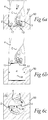
- Figs. 6a-c shows the tool assembly 1 used for drilling in a workpiece 50, wherein figs. 6a-b are side views with the workpiece in a sectional view, and fig. 6c is a top view with the tool body 4 shown in cross section.
- the tool assembly 1 is fastened to a spindle of a machine (not shown), rotating the tool body 4 about the centre axis C in a direction R while feeding the tool forward in a longitudinal feeding direction Z parallel with the centre axis C, toward the workpiece 50.
- the workpiece 50 is fed toward the tool. It is also possible to rotate the workpiece 50 instead of the tool body 4.
- the peripheral cutting edge 17 of the peripheral cutting insert 2 and a centre cutting edge 18 of the centre cutting insert 3 together drills a hole 51 with an inner diameter d in an upper surface 52 of the workpiece 50.
- the hole 51 has a centre axis M coinciding with the centre axis C of the tool body 4.
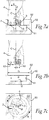
- Fig. 7a-c shows the tool assembly 1 used in a boring operation widening the hole 51 in the workpiece 50, wherein figs. 7a-b are side views with the workpiece in a sectional view, and fig. 7c is a top view with the tool body 4 shown in cross section.
- the workpiece is rotated about the axis M in the negative direction -R, while the tool assembly 1 is fixed in a non-rotating holder of a lathe, with the peripheral cutting edge 17 extending along a transverse feeding direction X, i.e. a direction perpendicular to the longitudinal feeding direction Z.
- the tool body 4 Prior to machining, the tool body 4 is displaced along the transverse feeding direction X by a distance e from the centre axis M of the hole 51.
- the tool is thereafter fed in the longitudinal feeding direction Z while rotating the workpiece in the negative direction -R about the axis M.
- the securing member 30 can be removed and the tool body 4 demounted from the coupling member 20.
- the tool body 4 may thereafter, thanks to the positioning of the force transfer means 40, easily be rotated 180° about the centre axis C and remounted to the coupling member.
- the peripheral cutting edge 17 still extends along the transverse feeding direction X, but the tool assembly 1 is now configured to be displaced in the negative feeding direction -X with respect to the workpiece 50.
- the cutting inserts 2, 3 are in the shown embodiment indexable cutting inserts which are detachably mounted in the insert seats 8, 9 of the tool body 4, using fastening means 19 in the form of screws.
- the configurations of the fastening means and of the cutting inserts may of course be varied as easily recognized by a person skilled in the art.
- the number of cutting inserts may be varied.
- the tool body may be provided with an insert seat configured to receive a cutting insert for threading applications.
- the coupling member may of course be of another type than the above described coupling member.
- the coupling member may be of HSK type, Varilock type, or taper type.
- the tool assembly may also be used in turning applications, i.e. for external machining of a rotating workpiece.
Landscapes
- Engineering & Computer Science (AREA)
- Mechanical Engineering (AREA)
- Cutting Tools, Boring Holders, And Turrets (AREA)
Abstract
Description
- The present invention relates to a tool body assembly for use in a tool assembly configured for chip-removing machining of a workpiece, to a tool assembly, and to a machine for chip-removing machining of a rotating workpiece. In particular, but not exclusively, the invention relates to a tool body assembly suitable for use in a machine such as a lathe, which machine is configured for chip-removing machining of a rotating workpiece. The tool body assembly, the tool assembly and the machine according to the invention are primarily intended for chip-removing machining of metallic workpieces.
- Tools comprising a drilling tool body equipped with indexable cutting inserts are normally used in drilling operations, wherein the tool is rotated about its centre axis and simultaneously fed along this axis toward/into a stationary workpiece, or wherein the workpiece is rotated and the tool is fixed for rotation in a holder. Such tools may sometimes also be used for other machining operations of a rotating workpiece, such as in a boring operation widening an internal diameter of a machined hole, or in a turning operation removing material from an external surface of the workpiece. Multi-purpose tools that may be used in a drilling operation as well as in subsequent boring and threading operations are also known. An example of such a multi-purpose tool is disclosed in
WO2008/088264 . The tool has a centre and a peripheral cutting insert, wherein the peripheral cutting insert is used for drilling as well as for boring. Furthermore, a cutting insert for threading is provided. - When a drilling tool is to be used for single-point machining of a rotating workpiece, the drilling tool body may be fastened to a non-rotatable holder of a lathe. The lathe is usually movable in a longitudinal feeding direction, i.e. along the centre axis of the tool body, and in a transverse feeding direction perpendicular to the centre axis. In a boring operation, the workpiece is rotated while the tool is consecutively advanced and retreated in the longitudinal feeding direction and advanced in the transverse feeding direction, so that a peripheral cutting edge of the tool actively removes material from a periphery of the hole when the tool is advanced in the longitudinal feeding direction, thereby widening the hole. By rotating the tool 180° with respect to the holder, the transverse feeding direction can be reversed, using the same peripheral cutting edge for machining.
- In a machining operation with a rotating tool, the orientation of the edges with respect to a transverse feeding direction is continuously changing and is therefore irrelevant. However, when a tool adapted for drilling is mounted in a lathe and used for single-point machining, such as in a boring operation, the alignment of the peripheral cutting edge in, or essentially in, the transverse feeding direction is crucial for the quality of the hole. Alignment of the tool when changing tools and/or reorienting the tool to reverse the transverse feeding direction can therefore be time consuming.
- It would be desirable to, in at least some aspect, facilitate mounting of a drilling tool body which is to be used for single-point machining of a rotating workpiece. In particular, it would be desirable to facilitate alignment of a peripheral cutting edge of a drilling tool which is to be used for single-point machining of a rotating workpiece with a transverse feeding direction of the tool.
- To better address these concerns, a tool body assembly according to claim 1, a tool assembly according to
claim 11 and a machine according toclaim 12 are provided. The tool body assembly according to the invention comprises: - a drilling tool body having a front end and a rear end between which a centre axis and a peripheral envelope surface extend, wherein at least one peripheral insert seat for mounting of a peripheral cutting insert and at least one centre insert seat for mounting of a centre cutting insert are provided in the front end,
- a coupling member having a first end configured for engagement with the rear end of the drilling tool body, and a second end configured to be fastened to a holder of a machine,
- at least one securing member configured to prevent axial motion of the drilling tool body with respect to the coupling member,
- torque transfer means configured to transmit torque between the coupling member and the drilling tool body, wherein the torque transfer means are positioned to allow fastening of the drilling tool body to the coupling member in one of totally two available rotational positions separated by 180°.
- The tool assembly according to the invention comprises:
- the proposed tool body assembly,
- at least one peripheral cutting insert mounted in the at least one peripheral insert seat, and
- at least one centre cutting insert mounted in the at least one centre insert seat.
- The machine for chip-removing machining of a rotating workpiece according to the invention comprises:
- the proposed tool assembly,
- a holder configured to hold the coupling member in a fixed orientation, wherein the holder is movable with respect to the workpiece at least in a longitudinal feeding direction and in a transverse feeding direction,
- The drilling tool body will in the following also be referred to as "the tool body". "A tool" is to be understood as a tool body having cutting inserts mounted in the insert seats.
- By positioning the torque transfer means so that the drilling tool body, hereinafter also referred to as the tool body, can only be fastened to the coupling member in one of two rotational positions separated by 180°, it is ensured that the cutting edges of the tool will always be oriented in one of two ways with respect to the coupling member. This facilitates using the tool body assembly in single-point machining operations such as boring and turning, in which the tool body assembly is mounted in a non-rotating holder and an active peripheral cutting edge needs to be aligned with a transverse feeding direction of the tool. In particular, it facilitates changing of tool bodies. If the machine is aligned using a tool body assembly with a first tool body so that the peripheral cutting edge extends along the transverse feeding direction, the tool body assembly may thereafter be removed from the holder, and the first tool body may be exchanged for a second tool body having the same kind of force transfer means. When the tool body assembly including the second tool body is fastened to the holder, the peripheral cutting edge of the second tool body is automatically aligned in the transverse feeding direction. Likewise, if the first tool body is removed from the coupling member, rotated 180° about the centre axis and thereafter fastened again to the coupling member, the peripheral cutting edge is automatically aligned for use in the opposite transverse feeding direction. Thus, alignment of the peripheral cutting edge of a cutting insert mounted in the tool body with a transverse feeding direction of the tool is facilitated.
- It is to be understood that the coupling member should preferably be configured to be fastened to the holder of the machine, e.g. a lathe, in a fixed orientation. The coupling member should for this purpose comprise means for positioning it in a fixed orientation with respect to the holder.
- Of course, either one of the holder of the machine and the workpiece may be movable to achieve a relative movement of the holder with respect to the workpiece.
- According to one embodiment, the rear end of the drilling tool body comprises a male engagement member extending along the centre axis, and wherein the first end of the coupling member comprises a female engagement member configured to receive the male engagement member of the drilling tool body. This configuration is preferable to achieve a desired strength of the tool body and for achieving an efficient duct system for providing liquid coolant to cutting edges at the front end of the tool. Of course, it may instead be possible to provide the tool body with a female engagement member at its rear end, and provide the first end of the coupling member with a corresponding male engagement member.
- According to one embodiment, a protruding flange is formed between the male engagement member and the front end of the drilling tool body, and the securing member is an annular securing member configured to be mounted around the flange of the drilling tool body and be securely engaged with the first end of the coupling member when the male engagement member is received in the female engagement member. In this embodiment, the securing member is configured to make contact with the flange such that axial motion of the tool body with respect to the coupling member is prevented. The securing member may e.g. be configured to be engaged with the first end of the coupling member by means of threaded engagement. This is an efficient way of securing the tool body in the axial direction.
- According to one embodiment, the torque transfer means comprise pins, and a first set of recesses configured to receive a front end of the pins are provided in the rear end of the drilling tool body and a second set of recesses configured to receive a rear end of the pins are provided in the first end of the coupling member. The pins may be formed of a different material than the tool body and the coupling member, and may thereby be tailored to have suitable mechanical properties. This kind of torque transfer means also offer a high precision and are relatively easy to provide, since the recesses can be made with a circular cross section using standard machining operations.
- According to one embodiment, the pins are fixedly fitted in one of the sets of recesses and the pins are configured to be releasably received in the other one of the sets of recesses. For example, the pins can be press fitted or shrink fitted in one of the sets of recesses. Having the pins fixedly mounted facilitates mounting of the tool body to the coupling member.
- According to one embodiment, the pins are fixedly fitted in the second set of recesses, i.e. on the first end of the coupling member. This is usually more material efficient, since the same coupling member can be used with various tool bodies.
- According to one embodiment, the torque transfer means comprise at least four pins. This improves the rigidity and strength of the torque transfer means.
- According to one embodiment, the torque transfer means comprise four pins that together form the four corners of an imaginary oblong. The imaginary oblong is preferably centred on the centre axis, i.e. all pins are located at the same radial distance from the centre axis. With this configuration of the torque transfer means, it is easy to intuitively understand which the two available rotational positions are.
- According to one embodiment, the torque transfer means comprise four pins, wherein a first pair of opposite pins are located at a first radial distance from the centre axis and wherein a second pair of opposite pins are located at a second radial distance from the centre axis, wherein the second radial distance is different from the first radial distance. This is an alternative to the oblong shape.
- According to one embodiment, the first set of recesses are formed in a peripheral rim of the flange. This facilitates engagement of the rear end of the tool body with the coupling member, since the recesses are clearly visible during mounting. Furthermore, the peripheral positioning improves the torque transfer.
- The proposed tool assembly may comprise one or more additional cutting inserts apart from the centre cutting insert and the peripheral cutting insert. For example, the tool assembly may comprise a threading, grooving, step and/or chamfer cutting insert.
- Further advantageous features and advantages of the invention will appear from the following detailed description.
- Embodiments of the invention will in the following be described by means of example with reference to the appended drawings, in which:
- Fig. 1
- is a perspective view of a tool assembly according to an embodiment,
- Fig. 2
- is an exploded perspective view of the tool assembly in
fig. 1 , - Fig. 3
- is a partially sectional side view of the tool assembly in
fig. 1 , - Fig. 4
- is a first end view of a coupling member of the tool assembly in
fig. 1 , - Fig. 5
- is a rear end view of a tool body of the tool assembly in
fig. 1 , - Figs. 6a-c
- show drilling in a stationary workpiece using the tool assembly in
fig. 1 , and - Figs. 7a-c
- show boring in a rotating workpiece using the tool assembly in
fig. 1 . - A tool assembly 1 according to an embodiment of the invention is shown in
figs. 1-3 . The tool assembly 1 is configured to be mounted in a holder of a machine (not shown) and be used on one hand in drilling operations, and on the other hand in boring and/or turning operations. The tool assembly 1 comprises a tool body assembly, aperipheral cutting insert 2, and acentre cutting insert 3, wherein atool body 4 of the tool body assembly together with the cutting inserts 2, 3 form a tool. The tool assembly is rotatable in a direction R about a centre axis C. - The
tool body 4 is a drilling tool body having afront end 5 and arear end 6 between which aperipheral envelope surface 7 extends. Aperipheral insert seat 8 for mounting of theperipheral cutting insert 2 and acentre insert seat 9 for mounting of thecentre cutting insert 3 are provided in thefront end 5 of thetool body 4. Two helical chip flutes 10 extend rearward from theinsert seats flange 11. Rearward of the protrudingflange 11, at therear end 6 of thetool body 4, amale engagement member 12 centred on and extending along the centre axis C is provided. - A
coupling member 20 to which thetool body 4 can be attached is also provided. In the shown embodiment, the coupling member has a basic shape of a coupling member used in a machine tool interface sold under the trade name Coromant Capto®. Thecoupling member 20 extends along the centre axis C from afirst end 21 to asecond end 22. Thefirst end 21 is configured to engage with therear end 6 of thetool body 4. For this purpose, thefirst end 21 of thecoupling member 20 comprises afemale engagement member 23 in the form of a central cavity, configured to receive themale engagement member 12 of thetool body 4. Thefemale engagement member 23 forms part of acentral duct 24 extending through thecoupling member 20, enabling supply of coolant to cooling channels within thetool body 4. - A
first end surface 25 of thecoupling member 20 is configured to make contact with arear contact surface 13 of theflange 11 of thetool body 4 as thetool body 4 and thecoupling member 20 are assembled. Thesurfaces figs. 4 and 5 , respectively, whereinfig. 4 shows a first end view of thecoupling member 20 andfig. 5 shows a rear end view of thetool body 4. An externally threadedsection 26 extends rearward from thefirst end surface 25. - At the
second end 22 of thecoupling member 20, a taperedhollow tri-polygon shank 29 for fastening the coupling member to a holder of a machine in a fixed orientation is provided. Theshank 29 extends along the centre axis C and is configured to transfer torque between the coupling member and the holder via a peripheral surface of theshank 29. Arecess 28 for receiving a protruding positioning member of the holder (not shown) is also provided, so that thecoupling member 20 can only be fastened to the holder in one orientation. - An annular securing
member 30 configured to prevent axial motion of thedrilling tool body 4 with respect to thecoupling member 20 is furthermore provided. The securingmember 30 is configured to be mounted around theflange 11 of thetool body 4 and be securely engaged with thefirst end 21 of thecoupling member 20 when themale engagement member 12 is received in thefemale engagement member 23. For this purpose, the securingmember 30 is internally threaded. Aninner contact surface 31 of the securingmember 30 is configured to press against afront contact surface 14 of the flange so that relative axial motion of thetool body 4 and thecoupling member 20 is prevented. - The tool body assembly further comprises torque transfer means 40 configured to transmit torque between the coupling
member 20 and thetool body 4 in an interface between thetool body 4 and thecoupling member 20. The torque transfer means 40 comprise fourcylindrical pins 41, wherein rear ends 42 of thepins 41 are fixedly fitted intorecesses 27 formed in thefirst end surface 25 of thecoupling member 20. Front ends 43 of thepins 41 are configured to be releasably received in correspondingrecesses 15 formed in therear contact surface 13 of theflange 11. Therecesses 15 are distributed around aperipheral rim 16 of theflange 11, i.e. therecesses 15 are formed in a transition between therim 16 and therear contact surface 13. - The fixed pins 41 and the
recesses 15 in theflange 11 are positioned to allow fastening of thetool body 4 to thecoupling member 20 in one of totally two available rotational positions separated by 180° about the centre axis C. In the shown embodiment, this has been accomplished by positioning thepins 41 as four corners of an imaginary oblong centred on the centre axis C, wherein the oblong has a short side with a length a1 and a long side with a length a2. In other words, thepins 41 are positioned with two different angular separations. In the shown embodiment, the pins have been positioned at 0°, 60°, 180° and 240°, i.e. with a first angular separation α1 of 60° for twopins 41 separated by the distance a1 and a second angular separation α2 of 120° for twopins 41 separated by the distance a2. The angular separations may of course be varied, but should be selected so that the two sides of the imaginary oblong can easily be distinguished for allowing intuitive mounting of thetool body 4 to thecoupling member 20. - The fixed pins 41 are positioned so that a section in a plane containing the centre axis C and the
recess 28 also cuts through two of thepins 41, positioned at opposite corners, such as shown infig. 3 . Aperipheral cutting edge 17 of theperipheral cutting insert 2 thereby extends in a perpendicular or essentially perpendicular direction to a plane of the section. -
Figs. 6a-c shows the tool assembly 1 used for drilling in aworkpiece 50, whereinfigs. 6a-b are side views with the workpiece in a sectional view, andfig. 6c is a top view with thetool body 4 shown in cross section. The tool assembly 1 is fastened to a spindle of a machine (not shown), rotating thetool body 4 about the centre axis C in a direction R while feeding the tool forward in a longitudinal feeding direction Z parallel with the centre axis C, toward theworkpiece 50. Alternatively, theworkpiece 50 is fed toward the tool. It is also possible to rotate theworkpiece 50 instead of thetool body 4. Theperipheral cutting edge 17 of theperipheral cutting insert 2 and acentre cutting edge 18 of thecentre cutting insert 3 together drills ahole 51 with an inner diameter d in anupper surface 52 of theworkpiece 50. Thehole 51 has a centre axis M coinciding with the centre axis C of thetool body 4. -
Fig. 7a-c shows the tool assembly 1 used in a boring operation widening thehole 51 in theworkpiece 50, whereinfigs. 7a-b are side views with the workpiece in a sectional view, andfig. 7c is a top view with thetool body 4 shown in cross section. In this operation, the workpiece is rotated about the axis M in the negative direction -R, while the tool assembly 1 is fixed in a non-rotating holder of a lathe, with theperipheral cutting edge 17 extending along a transverse feeding direction X, i.e. a direction perpendicular to the longitudinal feeding direction Z. Prior to machining, thetool body 4 is displaced along the transverse feeding direction X by a distance e from the centre axis M of thehole 51. The tool is thereafter fed in the longitudinal feeding direction Z while rotating the workpiece in the negative direction -R about the axis M. Thehole 51 is thereby widened to an inner diameter D=d+2e. In the boring operation, only theperipheral cutting edge 17 is active, while thecentre cutting edge 18 is inactive. - After removal of the tool assembly 1 from the holder of the lathe, the securing
member 30 can be removed and thetool body 4 demounted from thecoupling member 20. Thetool body 4 may thereafter, thanks to the positioning of the force transfer means 40, easily be rotated 180° about the centre axis C and remounted to the coupling member. When the tool assembly 1 is again attached to the holder of the lathe, theperipheral cutting edge 17 still extends along the transverse feeding direction X, but the tool assembly 1 is now configured to be displaced in the negative feeding direction -X with respect to theworkpiece 50. - The cutting inserts 2, 3 are in the shown embodiment indexable cutting inserts which are detachably mounted in the
insert seats tool body 4, using fastening means 19 in the form of screws. The configurations of the fastening means and of the cutting inserts may of course be varied as easily recognized by a person skilled in the art. Moreover, the number of cutting inserts may be varied. For example, the tool body may be provided with an insert seat configured to receive a cutting insert for threading applications. - The coupling member may of course be of another type than the above described coupling member. For example, the coupling member may be of HSK type, Varilock type, or taper type.
- The tool assembly may also be used in turning applications, i.e. for external machining of a rotating workpiece.
- The invention is of course not limited to the embodiments disclosed, but may be varied and modified within the scope of the following claims.
Claims (12)
- A tool body assembly for use in a tool assembly configured for chip-removing machining of a workpiece (50), the tool body assembly comprising:- a drilling tool body (4) having a front end (5) and a rear end (6) between which a centre axis (C) and a peripheral envelope surface (7) extend, wherein at least one peripheral insert seat (8) for mounting of a peripheral cutting insert (2) and at least one centre insert seat (9) for mounting of a centre cutting insert (3) are provided in the front end (5),- a coupling member (20) having a first end (21) configured for engagement with the rear end (6) of the drilling tool body (4), and a second end (22) configured to be fastened to a holder of a machine,- at least one securing member (30) configured to prevent axial motion of the drilling tool body (4) with respect to the coupling member (20),- torque transfer means (40) configured to transmit torque between the coupling member (20) and the drilling tool body (4), wherein the torque transfer means (40) are positioned to allow fastening of the drilling tool body (4) to the coupling member (20) in one of totally two available rotational positions separated by 180°.
- The tool body assembly according to claim 1, wherein the rear end (6) of the drilling tool body (4) comprises a male engagement member (12) extending along the centre axis (C), and wherein the first end (21) of the coupling member (20) comprises a female engagement member (23) configured to receive the male engagement member (12) of the drilling tool body (4).
- The tool body assembly according to claim 2, wherein a protruding flange (11) is formed between the male engagement member (12) and the front end (5) of the drilling tool body (4), and wherein the securing member (30) is an annular securing member configured to be mounted around the flange (11) of the drilling tool body (4) and be securely engaged with the first end (21) of the coupling member (20) when the male engagement member (12) is received in the female engagement member (23).
- The tool body assembly according to any one of the preceding claims, wherein the torque transfer means (40) comprise pins (41), and wherein a first set of recesses (15) configured to receive a front end (43) of the pins (41) are provided in the rear end (6) of the drilling tool body (4) and wherein a second set of recesses (27) configured to receive a rear end (42) of the pins (41) are provided in the first end (21) of the coupling member (20).
- The tool body assembly according to claim 4, wherein the pins (41) are fixedly fitted in one of the sets of recesses (15, 27) and wherein the pins (41) are configured to be releasably received in the other one of the sets of recesses (15, 27).
- The tool body according to claim 5, wherein the pins (41) are fixedly fitted in the second set of recesses (27).
- The tool body assembly according to any one of claims 4-6, wherein the torque transfer means (40) comprise at least four pins (41).
- The tool body assembly according to any one of claims 4-6, wherein the torque transfer means (40) comprise four pins (41) that together form the four corners of an imaginary oblong.
- The tool body assembly according to any one of claims 4-6, wherein the torque transfer means (40) comprise four pins, wherein a first pair of opposite pins are located at a first radial distance from the centre axis (C) and wherein a second pair of opposite pins are located at a second radial distance from the centre axis (C), wherein the second radial distance is different from the first radial distance.
- The tool body assembly according to any one of claims 5-9 in combination with claim 3, wherein the first set of recesses (15) are formed in a peripheral rim (16) of the flange (11).
- A tool assembly (1) for chip-removing machining, comprising:- a tool body assembly according to any one of the preceding claims,- at least one peripheral cutting insert (2) mounted in the at least one peripheral insert seat (8), and- at least one centre cutting insert (3) mounted in the at least one centre insert seat (9).
- A machine for chip-removing machining of a rotating workpiece, wherein the machine comprises:- a tool assembly (1) according to claim 11,- a holder configured to hold the coupling member (20) in a fixed orientation, wherein the holder is movable with respect to the workpiece at least in a longitudinal feeding direction (Z) and in a transverse feeding direction (X),wherein, when the tool assembly (1) is mounted to the holder in the fixed orientation, a peripheral cutting edge (17) of the at least one peripheral cutting insert (2) extends along the transverse feeding direction (X).
Priority Applications (1)
| Application Number | Priority Date | Filing Date | Title |
|---|---|---|---|
| EP17206320.8A EP3495080B1 (en) | 2017-12-11 | 2017-12-11 | A tool body assembly, a tool assembly and a machine |
Applications Claiming Priority (1)
| Application Number | Priority Date | Filing Date | Title |
|---|---|---|---|
| EP17206320.8A EP3495080B1 (en) | 2017-12-11 | 2017-12-11 | A tool body assembly, a tool assembly and a machine |
Publications (2)
| Publication Number | Publication Date |
|---|---|
| EP3495080A1 true EP3495080A1 (en) | 2019-06-12 |
| EP3495080B1 EP3495080B1 (en) | 2022-07-06 |
Family
ID=60654815
Family Applications (1)
| Application Number | Title | Priority Date | Filing Date |
|---|---|---|---|
| EP17206320.8A Active EP3495080B1 (en) | 2017-12-11 | 2017-12-11 | A tool body assembly, a tool assembly and a machine |
Country Status (1)
| Country | Link |
|---|---|
| EP (1) | EP3495080B1 (en) |
Cited By (4)
| Publication number | Priority date | Publication date | Assignee | Title |
|---|---|---|---|---|
| USD1009108S1 (en) | 2020-09-21 | 2023-12-26 | Kyocera Unimerco Tooling A/S | Drill |
| US11982184B2 (en) | 2020-11-13 | 2024-05-14 | Milwaukee Electric Tool Corporation | Core drill assembly |
| DE102024102685A1 (en) | 2023-02-09 | 2024-08-14 | Iscar Ltd. | Modular cutting tool with integral center pin and torque transmission mechanism |
| US12515259B2 (en) | 2021-04-02 | 2026-01-06 | Milwaukee Electric Tool Corporation | Core drill |
Citations (3)
| Publication number | Priority date | Publication date | Assignee | Title |
|---|---|---|---|---|
| US20050161263A1 (en) * | 2003-12-25 | 2005-07-28 | Shibuya Company, Ltd. | Core bit for use with a core drill |
| WO2008088264A1 (en) | 2007-01-17 | 2008-07-24 | Sandvik Intellectual Property Ab | A rotatable multi-operation tool for chip removing machining, and a basic body therefor |
| EP1990113A1 (en) * | 2007-05-09 | 2008-11-12 | Taegutec Ltd. | Tool assembly |
-
2017
- 2017-12-11 EP EP17206320.8A patent/EP3495080B1/en active Active
Patent Citations (3)
| Publication number | Priority date | Publication date | Assignee | Title |
|---|---|---|---|---|
| US20050161263A1 (en) * | 2003-12-25 | 2005-07-28 | Shibuya Company, Ltd. | Core bit for use with a core drill |
| WO2008088264A1 (en) | 2007-01-17 | 2008-07-24 | Sandvik Intellectual Property Ab | A rotatable multi-operation tool for chip removing machining, and a basic body therefor |
| EP1990113A1 (en) * | 2007-05-09 | 2008-11-12 | Taegutec Ltd. | Tool assembly |
Cited By (6)
| Publication number | Priority date | Publication date | Assignee | Title |
|---|---|---|---|---|
| USD1009108S1 (en) | 2020-09-21 | 2023-12-26 | Kyocera Unimerco Tooling A/S | Drill |
| US11982184B2 (en) | 2020-11-13 | 2024-05-14 | Milwaukee Electric Tool Corporation | Core drill assembly |
| US12486721B2 (en) | 2020-11-13 | 2025-12-02 | Milwaukee Electric Tool Corporation | Core drill assembly |
| US12515259B2 (en) | 2021-04-02 | 2026-01-06 | Milwaukee Electric Tool Corporation | Core drill |
| DE102024102685A1 (en) | 2023-02-09 | 2024-08-14 | Iscar Ltd. | Modular cutting tool with integral center pin and torque transmission mechanism |
| US12605771B2 (en) * | 2023-02-09 | 2026-04-21 | Iscar, Ltd. | Modular cutting tool having integral central pin and torque transfer mechanism |
Also Published As
| Publication number | Publication date |
|---|---|
| EP3495080B1 (en) | 2022-07-06 |
Similar Documents
| Publication | Publication Date | Title |
|---|---|---|
| EP2964413B1 (en) | Drilling system for deep holes | |
| CA2658202C (en) | Drilling tool and method for producing port seals | |
| EP3299102B1 (en) | Tool body in combination with a first cutting insert and a second cutting insert | |
| US8690500B2 (en) | Tool interface | |
| US8360694B2 (en) | Rotatable multi-operation tool for chip removing machining, and a basic body therefor | |
| EP3495080B1 (en) | A tool body assembly, a tool assembly and a machine | |
| CN1612789B (en) | Tools and Fixtures | |
| EP2536522B1 (en) | Tool coupling | |
| CN102649179B (en) | Tool holder and with a tool holder and the tooling system of a cutter | |
| CN101301688A (en) | Tool assembly | |
| US20110206472A1 (en) | Drilling tool and method for producing port seals | |
| US20130089385A1 (en) | Collet chuck | |
| CN101066563B (en) | Error proofing apparatus for cutting tools | |
| US7320566B2 (en) | Cutting tool including detachable cutter head | |
| EP0659511B1 (en) | Tool system | |
| CN214236308U (en) | Multifunctional tailstock clamp of lathe | |
| CN112222906B (en) | Device for quick change of tool holder adapter | |
| CN111069665B (en) | Special milling cutter and chuck for numerical control milling machine | |
| JP2008110417A (en) | Arbor, fastening method between arbor and cutting head, and cutting head exchangeable tool | |
| JP2009291858A (en) | Boring tool | |
| CN220240131U (en) | Split type module drill | |
| WO2013008768A1 (en) | Cutting tool with exchangeable cutting edges | |
| CN210908147U (en) | Integrated combined tool and machining equipment suitable for hole machining and inner hole groove machining | |
| EP3330025B1 (en) | Cutting assembly with multiple cutting tools for milling | |
| CN211192372U (en) | PCD composite cutter for stepped hole |
Legal Events
| Date | Code | Title | Description |
|---|---|---|---|
| PUAI | Public reference made under article 153(3) epc to a published international application that has entered the european phase |
Free format text: ORIGINAL CODE: 0009012 |
|
| STAA | Information on the status of an ep patent application or granted ep patent |
Free format text: STATUS: THE APPLICATION HAS BEEN PUBLISHED |
|
| AK | Designated contracting states |
Kind code of ref document: A1 Designated state(s): AL AT BE BG CH CY CZ DE DK EE ES FI FR GB GR HR HU IE IS IT LI LT LU LV MC MK MT NL NO PL PT RO RS SE SI SK SM TR |
|
| AX | Request for extension of the european patent |
Extension state: BA ME |
|
| STAA | Information on the status of an ep patent application or granted ep patent |
Free format text: STATUS: REQUEST FOR EXAMINATION WAS MADE |
|
| 17P | Request for examination filed |
Effective date: 20191212 |
|
| RBV | Designated contracting states (corrected) |
Designated state(s): AL AT BE BG CH CY CZ DE DK EE ES FI FR GB GR HR HU IE IS IT LI LT LU LV MC MK MT NL NO PL PT RO RS SE SI SK SM TR |
|
| GRAP | Despatch of communication of intention to grant a patent |
Free format text: ORIGINAL CODE: EPIDOSNIGR1 |
|
| STAA | Information on the status of an ep patent application or granted ep patent |
Free format text: STATUS: GRANT OF PATENT IS INTENDED |
|
| RIC1 | Information provided on ipc code assigned before grant |
Ipc: B23B 51/12 20060101ALI20220128BHEP Ipc: B23B 51/00 20060101ALI20220128BHEP Ipc: B23B 31/11 20060101ALI20220128BHEP Ipc: B23B 31/00 20060101AFI20220128BHEP |
|
| INTG | Intention to grant announced |
Effective date: 20220304 |
|
| GRAS | Grant fee paid |
Free format text: ORIGINAL CODE: EPIDOSNIGR3 |
|
| GRAA | (expected) grant |
Free format text: ORIGINAL CODE: 0009210 |
|
| STAA | Information on the status of an ep patent application or granted ep patent |
Free format text: STATUS: THE PATENT HAS BEEN GRANTED |
|
| AK | Designated contracting states |
Kind code of ref document: B1 Designated state(s): AL AT BE BG CH CY CZ DE DK EE ES FI FR GB GR HR HU IE IS IT LI LT LU LV MC MK MT NL NO PL PT RO RS SE SI SK SM TR |
|
| REG | Reference to a national code |
Ref country code: AT Ref legal event code: REF Ref document number: 1502507 Country of ref document: AT Kind code of ref document: T Effective date: 20220715 Ref country code: CH Ref legal event code: EP |
|
| REG | Reference to a national code |
Ref country code: DE Ref legal event code: R096 Ref document number: 602017059188 Country of ref document: DE |
|
| REG | Reference to a national code |
Ref country code: IE Ref legal event code: FG4D |
|
| REG | Reference to a national code |
Ref country code: LT Ref legal event code: MG9D |
|
| REG | Reference to a national code |
Ref country code: NL Ref legal event code: MP Effective date: 20220706 |
|
| PG25 | Lapsed in a contracting state [announced via postgrant information from national office to epo] |
Ref country code: SE Free format text: LAPSE BECAUSE OF FAILURE TO SUBMIT A TRANSLATION OF THE DESCRIPTION OR TO PAY THE FEE WITHIN THE PRESCRIBED TIME-LIMIT Effective date: 20220706 Ref country code: RS Free format text: LAPSE BECAUSE OF FAILURE TO SUBMIT A TRANSLATION OF THE DESCRIPTION OR TO PAY THE FEE WITHIN THE PRESCRIBED TIME-LIMIT Effective date: 20220706 Ref country code: PT Free format text: LAPSE BECAUSE OF FAILURE TO SUBMIT A TRANSLATION OF THE DESCRIPTION OR TO PAY THE FEE WITHIN THE PRESCRIBED TIME-LIMIT Effective date: 20221107 Ref country code: NO Free format text: LAPSE BECAUSE OF FAILURE TO SUBMIT A TRANSLATION OF THE DESCRIPTION OR TO PAY THE FEE WITHIN THE PRESCRIBED TIME-LIMIT Effective date: 20221006 Ref country code: NL Free format text: LAPSE BECAUSE OF FAILURE TO SUBMIT A TRANSLATION OF THE DESCRIPTION OR TO PAY THE FEE WITHIN THE PRESCRIBED TIME-LIMIT Effective date: 20220706 Ref country code: LV Free format text: LAPSE BECAUSE OF FAILURE TO SUBMIT A TRANSLATION OF THE DESCRIPTION OR TO PAY THE FEE WITHIN THE PRESCRIBED TIME-LIMIT Effective date: 20220706 Ref country code: LT Free format text: LAPSE BECAUSE OF FAILURE TO SUBMIT A TRANSLATION OF THE DESCRIPTION OR TO PAY THE FEE WITHIN THE PRESCRIBED TIME-LIMIT Effective date: 20220706 Ref country code: FI Free format text: LAPSE BECAUSE OF FAILURE TO SUBMIT A TRANSLATION OF THE DESCRIPTION OR TO PAY THE FEE WITHIN THE PRESCRIBED TIME-LIMIT Effective date: 20220706 Ref country code: ES Free format text: LAPSE BECAUSE OF FAILURE TO SUBMIT A TRANSLATION OF THE DESCRIPTION OR TO PAY THE FEE WITHIN THE PRESCRIBED TIME-LIMIT Effective date: 20220706 |
|
| REG | Reference to a national code |
Ref country code: AT Ref legal event code: MK05 Ref document number: 1502507 Country of ref document: AT Kind code of ref document: T Effective date: 20220706 |
|
| PG25 | Lapsed in a contracting state [announced via postgrant information from national office to epo] |
Ref country code: PL Free format text: LAPSE BECAUSE OF FAILURE TO SUBMIT A TRANSLATION OF THE DESCRIPTION OR TO PAY THE FEE WITHIN THE PRESCRIBED TIME-LIMIT Effective date: 20220706 Ref country code: IS Free format text: LAPSE BECAUSE OF FAILURE TO SUBMIT A TRANSLATION OF THE DESCRIPTION OR TO PAY THE FEE WITHIN THE PRESCRIBED TIME-LIMIT Effective date: 20221106 Ref country code: HR Free format text: LAPSE BECAUSE OF FAILURE TO SUBMIT A TRANSLATION OF THE DESCRIPTION OR TO PAY THE FEE WITHIN THE PRESCRIBED TIME-LIMIT Effective date: 20220706 Ref country code: GR Free format text: LAPSE BECAUSE OF FAILURE TO SUBMIT A TRANSLATION OF THE DESCRIPTION OR TO PAY THE FEE WITHIN THE PRESCRIBED TIME-LIMIT Effective date: 20221007 |
|
| REG | Reference to a national code |
Ref country code: DE Ref legal event code: R097 Ref document number: 602017059188 Country of ref document: DE |
|
| PG25 | Lapsed in a contracting state [announced via postgrant information from national office to epo] |
Ref country code: SM Free format text: LAPSE BECAUSE OF FAILURE TO SUBMIT A TRANSLATION OF THE DESCRIPTION OR TO PAY THE FEE WITHIN THE PRESCRIBED TIME-LIMIT Effective date: 20220706 Ref country code: RO Free format text: LAPSE BECAUSE OF FAILURE TO SUBMIT A TRANSLATION OF THE DESCRIPTION OR TO PAY THE FEE WITHIN THE PRESCRIBED TIME-LIMIT Effective date: 20220706 Ref country code: DK Free format text: LAPSE BECAUSE OF FAILURE TO SUBMIT A TRANSLATION OF THE DESCRIPTION OR TO PAY THE FEE WITHIN THE PRESCRIBED TIME-LIMIT Effective date: 20220706 Ref country code: CZ Free format text: LAPSE BECAUSE OF FAILURE TO SUBMIT A TRANSLATION OF THE DESCRIPTION OR TO PAY THE FEE WITHIN THE PRESCRIBED TIME-LIMIT Effective date: 20220706 Ref country code: AT Free format text: LAPSE BECAUSE OF FAILURE TO SUBMIT A TRANSLATION OF THE DESCRIPTION OR TO PAY THE FEE WITHIN THE PRESCRIBED TIME-LIMIT Effective date: 20220706 |
|
| PLBE | No opposition filed within time limit |
Free format text: ORIGINAL CODE: 0009261 |
|
| STAA | Information on the status of an ep patent application or granted ep patent |
Free format text: STATUS: NO OPPOSITION FILED WITHIN TIME LIMIT |
|
| PG25 | Lapsed in a contracting state [announced via postgrant information from national office to epo] |
Ref country code: SK Free format text: LAPSE BECAUSE OF FAILURE TO SUBMIT A TRANSLATION OF THE DESCRIPTION OR TO PAY THE FEE WITHIN THE PRESCRIBED TIME-LIMIT Effective date: 20220706 Ref country code: EE Free format text: LAPSE BECAUSE OF FAILURE TO SUBMIT A TRANSLATION OF THE DESCRIPTION OR TO PAY THE FEE WITHIN THE PRESCRIBED TIME-LIMIT Effective date: 20220706 |
|
| 26N | No opposition filed |
Effective date: 20230411 |
|
| PG25 | Lapsed in a contracting state [announced via postgrant information from national office to epo] |
Ref country code: AL Free format text: LAPSE BECAUSE OF FAILURE TO SUBMIT A TRANSLATION OF THE DESCRIPTION OR TO PAY THE FEE WITHIN THE PRESCRIBED TIME-LIMIT Effective date: 20220706 |
|
| P01 | Opt-out of the competence of the unified patent court (upc) registered |
Effective date: 20230603 |
|
| REG | Reference to a national code |
Ref country code: CH Ref legal event code: PL |
|
| REG | Reference to a national code |
Ref country code: BE Ref legal event code: MM Effective date: 20221231 |
|
| PG25 | Lapsed in a contracting state [announced via postgrant information from national office to epo] |
Ref country code: SI Free format text: LAPSE BECAUSE OF FAILURE TO SUBMIT A TRANSLATION OF THE DESCRIPTION OR TO PAY THE FEE WITHIN THE PRESCRIBED TIME-LIMIT Effective date: 20220706 Ref country code: LU Free format text: LAPSE BECAUSE OF NON-PAYMENT OF DUE FEES Effective date: 20221211 |
|
| PG25 | Lapsed in a contracting state [announced via postgrant information from national office to epo] |
Ref country code: LI Free format text: LAPSE BECAUSE OF NON-PAYMENT OF DUE FEES Effective date: 20221231 Ref country code: IE Free format text: LAPSE BECAUSE OF NON-PAYMENT OF DUE FEES Effective date: 20221211 Ref country code: CH Free format text: LAPSE BECAUSE OF NON-PAYMENT OF DUE FEES Effective date: 20221231 |
|
| PG25 | Lapsed in a contracting state [announced via postgrant information from national office to epo] |
Ref country code: BE Free format text: LAPSE BECAUSE OF NON-PAYMENT OF DUE FEES Effective date: 20221231 |
|
| PG25 | Lapsed in a contracting state [announced via postgrant information from national office to epo] |
Ref country code: HU Free format text: LAPSE BECAUSE OF FAILURE TO SUBMIT A TRANSLATION OF THE DESCRIPTION OR TO PAY THE FEE WITHIN THE PRESCRIBED TIME-LIMIT; INVALID AB INITIO Effective date: 20171211 |
|
| PG25 | Lapsed in a contracting state [announced via postgrant information from national office to epo] |
Ref country code: CY Free format text: LAPSE BECAUSE OF FAILURE TO SUBMIT A TRANSLATION OF THE DESCRIPTION OR TO PAY THE FEE WITHIN THE PRESCRIBED TIME-LIMIT Effective date: 20220706 |
|
| PG25 | Lapsed in a contracting state [announced via postgrant information from national office to epo] |
Ref country code: MK Free format text: LAPSE BECAUSE OF FAILURE TO SUBMIT A TRANSLATION OF THE DESCRIPTION OR TO PAY THE FEE WITHIN THE PRESCRIBED TIME-LIMIT Effective date: 20220706 |
|
| PG25 | Lapsed in a contracting state [announced via postgrant information from national office to epo] |
Ref country code: MC Free format text: LAPSE BECAUSE OF FAILURE TO SUBMIT A TRANSLATION OF THE DESCRIPTION OR TO PAY THE FEE WITHIN THE PRESCRIBED TIME-LIMIT Effective date: 20220706 |
|
| PG25 | Lapsed in a contracting state [announced via postgrant information from national office to epo] |
Ref country code: MC Free format text: LAPSE BECAUSE OF FAILURE TO SUBMIT A TRANSLATION OF THE DESCRIPTION OR TO PAY THE FEE WITHIN THE PRESCRIBED TIME-LIMIT Effective date: 20220706 |
|
| PG25 | Lapsed in a contracting state [announced via postgrant information from national office to epo] |
Ref country code: BG Free format text: LAPSE BECAUSE OF FAILURE TO SUBMIT A TRANSLATION OF THE DESCRIPTION OR TO PAY THE FEE WITHIN THE PRESCRIBED TIME-LIMIT Effective date: 20220706 |
|
| PG25 | Lapsed in a contracting state [announced via postgrant information from national office to epo] |
Ref country code: MT Free format text: LAPSE BECAUSE OF FAILURE TO SUBMIT A TRANSLATION OF THE DESCRIPTION OR TO PAY THE FEE WITHIN THE PRESCRIBED TIME-LIMIT Effective date: 20220706 |
|
| PG25 | Lapsed in a contracting state [announced via postgrant information from national office to epo] |
Ref country code: TR Free format text: LAPSE BECAUSE OF FAILURE TO SUBMIT A TRANSLATION OF THE DESCRIPTION OR TO PAY THE FEE WITHIN THE PRESCRIBED TIME-LIMIT Effective date: 20220706 |
|
| PGFP | Annual fee paid to national office [announced via postgrant information from national office to epo] |
Ref country code: DE Payment date: 20251028 Year of fee payment: 9 |
|
| PGFP | Annual fee paid to national office [announced via postgrant information from national office to epo] |
Ref country code: GB Payment date: 20251030 Year of fee payment: 9 |
|
| PGFP | Annual fee paid to national office [announced via postgrant information from national office to epo] |
Ref country code: IT Payment date: 20251121 Year of fee payment: 9 |
|
| PGFP | Annual fee paid to national office [announced via postgrant information from national office to epo] |
Ref country code: FR Payment date: 20251124 Year of fee payment: 9 |