EP3495076A1 - Aluminum alloy particle with a permanent magnet core - Google Patents
Aluminum alloy particle with a permanent magnet core Download PDFInfo
- Publication number
- EP3495076A1 EP3495076A1 EP18210679.9A EP18210679A EP3495076A1 EP 3495076 A1 EP3495076 A1 EP 3495076A1 EP 18210679 A EP18210679 A EP 18210679A EP 3495076 A1 EP3495076 A1 EP 3495076A1
- Authority
- EP
- European Patent Office
- Prior art keywords
- aluminum alloy
- component
- magnetic
- particle
- coating
- Prior art date
- Legal status (The legal status is an assumption and is not a legal conclusion. Google has not performed a legal analysis and makes no representation as to the accuracy of the status listed.)
- Granted
Links
Images


Classifications
-
- H—ELECTRICITY
- H01—ELECTRIC ELEMENTS
- H01F—MAGNETS; INDUCTANCES; TRANSFORMERS; SELECTION OF MATERIALS FOR THEIR MAGNETIC PROPERTIES
- H01F1/00—Magnets or magnetic bodies characterised by the magnetic materials therefor; Selection of materials for their magnetic properties
- H01F1/01—Magnets or magnetic bodies characterised by the magnetic materials therefor; Selection of materials for their magnetic properties of inorganic materials
- H01F1/03—Magnets or magnetic bodies characterised by the magnetic materials therefor; Selection of materials for their magnetic properties of inorganic materials characterised by their coercivity
- H01F1/032—Magnets or magnetic bodies characterised by the magnetic materials therefor; Selection of materials for their magnetic properties of inorganic materials characterised by their coercivity of hard-magnetic materials
- H01F1/04—Magnets or magnetic bodies characterised by the magnetic materials therefor; Selection of materials for their magnetic properties of inorganic materials characterised by their coercivity of hard-magnetic materials metals or alloys
- H01F1/047—Alloys characterised by their composition
- H01F1/053—Alloys characterised by their composition containing rare earth metals
-
- B—PERFORMING OPERATIONS; TRANSPORTING
- B22—CASTING; POWDER METALLURGY
- B22F—WORKING METALLIC POWDER; MANUFACTURE OF ARTICLES FROM METALLIC POWDER; MAKING METALLIC POWDER; APPARATUS OR DEVICES SPECIALLY ADAPTED FOR METALLIC POWDER
- B22F1/00—Metallic powder; Treatment of metallic powder, e.g. to facilitate working or to improve properties
- B22F1/17—Metallic particles coated with metal
-
- B—PERFORMING OPERATIONS; TRANSPORTING
- B22—CASTING; POWDER METALLURGY
- B22F—WORKING METALLIC POWDER; MANUFACTURE OF ARTICLES FROM METALLIC POWDER; MAKING METALLIC POWDER; APPARATUS OR DEVICES SPECIALLY ADAPTED FOR METALLIC POWDER
- B22F10/00—Additive manufacturing of workpieces or articles from metallic powder
- B22F10/20—Direct sintering or melting
- B22F10/28—Powder bed fusion, e.g. selective laser melting [SLM] or electron beam melting [EBM]
-
- B—PERFORMING OPERATIONS; TRANSPORTING
- B33—ADDITIVE MANUFACTURING TECHNOLOGY
- B33Y—ADDITIVE MANUFACTURING, i.e. MANUFACTURING OF THREE-DIMENSIONAL [3D] OBJECTS BY ADDITIVE DEPOSITION, ADDITIVE AGGLOMERATION OR ADDITIVE LAYERING, e.g. BY 3D PRINTING, STEREOLITHOGRAPHY OR SELECTIVE LASER SINTERING
- B33Y70/00—Materials specially adapted for additive manufacturing
- B33Y70/10—Composites of different types of material, e.g. mixtures of ceramics and polymers or mixtures of metals and biomaterials
-
- B—PERFORMING OPERATIONS; TRANSPORTING
- B33—ADDITIVE MANUFACTURING TECHNOLOGY
- B33Y—ADDITIVE MANUFACTURING, i.e. MANUFACTURING OF THREE-DIMENSIONAL [3D] OBJECTS BY ADDITIVE DEPOSITION, ADDITIVE AGGLOMERATION OR ADDITIVE LAYERING, e.g. BY 3D PRINTING, STEREOLITHOGRAPHY OR SELECTIVE LASER SINTERING
- B33Y80/00—Products made by additive manufacturing
-
- H—ELECTRICITY
- H01—ELECTRIC ELEMENTS
- H01F—MAGNETS; INDUCTANCES; TRANSFORMERS; SELECTION OF MATERIALS FOR THEIR MAGNETIC PROPERTIES
- H01F1/00—Magnets or magnetic bodies characterised by the magnetic materials therefor; Selection of materials for their magnetic properties
- H01F1/01—Magnets or magnetic bodies characterised by the magnetic materials therefor; Selection of materials for their magnetic properties of inorganic materials
- H01F1/03—Magnets or magnetic bodies characterised by the magnetic materials therefor; Selection of materials for their magnetic properties of inorganic materials characterised by their coercivity
- H01F1/032—Magnets or magnetic bodies characterised by the magnetic materials therefor; Selection of materials for their magnetic properties of inorganic materials characterised by their coercivity of hard-magnetic materials
- H01F1/04—Magnets or magnetic bodies characterised by the magnetic materials therefor; Selection of materials for their magnetic properties of inorganic materials characterised by their coercivity of hard-magnetic materials metals or alloys
- H01F1/06—Magnets or magnetic bodies characterised by the magnetic materials therefor; Selection of materials for their magnetic properties of inorganic materials characterised by their coercivity of hard-magnetic materials metals or alloys in the form of particles, e.g. powder
- H01F1/061—Magnets or magnetic bodies characterised by the magnetic materials therefor; Selection of materials for their magnetic properties of inorganic materials characterised by their coercivity of hard-magnetic materials metals or alloys in the form of particles, e.g. powder with a protective layer
-
- H—ELECTRICITY
- H01—ELECTRIC ELEMENTS
- H01F—MAGNETS; INDUCTANCES; TRANSFORMERS; SELECTION OF MATERIALS FOR THEIR MAGNETIC PROPERTIES
- H01F1/00—Magnets or magnetic bodies characterised by the magnetic materials therefor; Selection of materials for their magnetic properties
- H01F1/01—Magnets or magnetic bodies characterised by the magnetic materials therefor; Selection of materials for their magnetic properties of inorganic materials
- H01F1/03—Magnets or magnetic bodies characterised by the magnetic materials therefor; Selection of materials for their magnetic properties of inorganic materials characterised by their coercivity
- H01F1/032—Magnets or magnetic bodies characterised by the magnetic materials therefor; Selection of materials for their magnetic properties of inorganic materials characterised by their coercivity of hard-magnetic materials
- H01F1/04—Magnets or magnetic bodies characterised by the magnetic materials therefor; Selection of materials for their magnetic properties of inorganic materials characterised by their coercivity of hard-magnetic materials metals or alloys
- H01F1/06—Magnets or magnetic bodies characterised by the magnetic materials therefor; Selection of materials for their magnetic properties of inorganic materials characterised by their coercivity of hard-magnetic materials metals or alloys in the form of particles, e.g. powder
- H01F1/08—Magnets or magnetic bodies characterised by the magnetic materials therefor; Selection of materials for their magnetic properties of inorganic materials characterised by their coercivity of hard-magnetic materials metals or alloys in the form of particles, e.g. powder pressed, sintered, or bound together
- H01F1/083—Magnets or magnetic bodies characterised by the magnetic materials therefor; Selection of materials for their magnetic properties of inorganic materials characterised by their coercivity of hard-magnetic materials metals or alloys in the form of particles, e.g. powder pressed, sintered, or bound together in a bonding agent
-
- H—ELECTRICITY
- H01—ELECTRIC ELEMENTS
- H01F—MAGNETS; INDUCTANCES; TRANSFORMERS; SELECTION OF MATERIALS FOR THEIR MAGNETIC PROPERTIES
- H01F13/00—Apparatus or processes for magnetising or demagnetising
- H01F13/003—Methods and devices for magnetising permanent magnets
-
- H—ELECTRICITY
- H01—ELECTRIC ELEMENTS
- H01F—MAGNETS; INDUCTANCES; TRANSFORMERS; SELECTION OF MATERIALS FOR THEIR MAGNETIC PROPERTIES
- H01F3/00—Cores, Yokes, or armatures
- H01F3/08—Cores, Yokes, or armatures made from powder
-
- H—ELECTRICITY
- H01—ELECTRIC ELEMENTS
- H01F—MAGNETS; INDUCTANCES; TRANSFORMERS; SELECTION OF MATERIALS FOR THEIR MAGNETIC PROPERTIES
- H01F41/00—Apparatus or processes specially adapted for manufacturing or assembling magnets, inductances or transformers; Apparatus or processes specially adapted for manufacturing materials characterised by their magnetic properties
- H01F41/02—Apparatus or processes specially adapted for manufacturing or assembling magnets, inductances or transformers; Apparatus or processes specially adapted for manufacturing materials characterised by their magnetic properties for manufacturing cores, coils, or magnets
- H01F41/0253—Apparatus or processes specially adapted for manufacturing or assembling magnets, inductances or transformers; Apparatus or processes specially adapted for manufacturing materials characterised by their magnetic properties for manufacturing cores, coils, or magnets for manufacturing permanent magnets
-
- H—ELECTRICITY
- H01—ELECTRIC ELEMENTS
- H01F—MAGNETS; INDUCTANCES; TRANSFORMERS; SELECTION OF MATERIALS FOR THEIR MAGNETIC PROPERTIES
- H01F41/00—Apparatus or processes specially adapted for manufacturing or assembling magnets, inductances or transformers; Apparatus or processes specially adapted for manufacturing materials characterised by their magnetic properties
- H01F41/14—Apparatus or processes specially adapted for manufacturing or assembling magnets, inductances or transformers; Apparatus or processes specially adapted for manufacturing materials characterised by their magnetic properties for applying magnetic films to substrates
- H01F41/16—Apparatus or processes specially adapted for manufacturing or assembling magnets, inductances or transformers; Apparatus or processes specially adapted for manufacturing materials characterised by their magnetic properties for applying magnetic films to substrates the magnetic material being applied in the form of particles, e.g. by serigraphy, to form thick magnetic films or precursors therefor
-
- B—PERFORMING OPERATIONS; TRANSPORTING
- B22—CASTING; POWDER METALLURGY
- B22F—WORKING METALLIC POWDER; MANUFACTURE OF ARTICLES FROM METALLIC POWDER; MAKING METALLIC POWDER; APPARATUS OR DEVICES SPECIALLY ADAPTED FOR METALLIC POWDER
- B22F10/00—Additive manufacturing of workpieces or articles from metallic powder
- B22F10/20—Direct sintering or melting
- B22F10/25—Direct deposition of metal particles, e.g. direct metal deposition [DMD] or laser engineered net shaping [LENS]
-
- C—CHEMISTRY; METALLURGY
- C22—METALLURGY; FERROUS OR NON-FERROUS ALLOYS; TREATMENT OF ALLOYS OR NON-FERROUS METALS
- C22C—ALLOYS
- C22C2202/00—Physical properties
- C22C2202/02—Magnetic
-
- Y—GENERAL TAGGING OF NEW TECHNOLOGICAL DEVELOPMENTS; GENERAL TAGGING OF CROSS-SECTIONAL TECHNOLOGIES SPANNING OVER SEVERAL SECTIONS OF THE IPC; TECHNICAL SUBJECTS COVERED BY FORMER USPC CROSS-REFERENCE ART COLLECTIONS [XRACs] AND DIGESTS
- Y02—TECHNOLOGIES OR APPLICATIONS FOR MITIGATION OR ADAPTATION AGAINST CLIMATE CHANGE
- Y02P—CLIMATE CHANGE MITIGATION TECHNOLOGIES IN THE PRODUCTION OR PROCESSING OF GOODS
- Y02P10/00—Technologies related to metal processing
- Y02P10/25—Process efficiency
Definitions
- the resulting components can be brittle and difficult to machine.
- Adding aluminum alloys to the feedstock can improve the workability of a manufactured component, but the reflectivity of some aluminum alloys can interfere with the laser during manufacturing.
- a particle for use in a powder-based additive manufacturing process includes a magnetic core having a first magnetic permeability, and an aluminum alloy coating surrounding the magnetic core.
- the aluminum alloy coating has a second magnetic permeability lower than the first magnetic permeability.
- a three-dimensional magnetic component includes an aluminum alloy matrix, and a plurality of particles dispersed throughout the matrix.
- Each of the particles includes a magnetic core having a first magnetic permeability, and an aluminum alloy coating surrounding the magnetic core.
- the aluminum alloy coating has a second magnetic permeability lower than the first magnetic permeability.
- a method of making a three-dimensional magnetic component includes applying a layer of a feedstock to a build substrate, and fusing the layer using an energy source.
- the feedstock includes a plurality of magnetic particles having a permanent magnetic core and an aluminum alloy coating surrounding the permanent magnetic core.
- the present invention is directed to particles for use as a feedstock for manufacturing magnetic components.
- the particles include a magnetic core coated with an aluminum-silicon alloy.
- the particles can further include an optional outer silicon coating.
- the particles can be included in a feedstock used to produce a magnetic component.
- An aluminum alloy powder can be added to the feedstock to enhance an aluminum matrix surrounding the fused particles.
- the resulting components have a more robust microstructure and can be formed with more complex geometries than those produced using current manufacturing methods and materials.
- FIG. 1 is an enlarged cross-section of magnetic particle 10.
- Particle 10 includes magnetic core 12 and aluminum-silicon coating 14 surrounding core 12.
- Particle 10, as shown, also includes coating 16, although exemplary embodiments of particle 10 do not require coating 16.
- Core 12 is formed from a sintered powder of magnetic material.
- the material can be a permanent magnetic material formed from rare earth elements.
- core 12 can be formed from an alloy of samarium or neodymium.
- Other suitable permanent magnet materials, such as ceramics, ferrites, and manganese bismuth are contemplated herein.
- Coating 14 is an aluminum alloy of a composition that is considered suitable for welding added to enhance the material properties of particle 10. For example, such alloys experience less solidification cracking than other materials. Suitable alloys for coating 14 can be Al12Si, AlSi10Mg, Aluminum 356.0, or Aluminum 357.0, to name a few, non-limiting examples. Other alloys, such as a 6000 series aluminum alloy, are contemplated herein. Coating 14 has low magnetic permeability ( ⁇ ) compared to core 12, such that coating 14 does not interfere with a magnetic field generated within core 12.
- Coating 14 can be applied to core(s) 12 using a fluidized bed powder coating process, during which heated cores 12 are immersed in a container of an aluminum-silicon alloy powder, or are passed through a cloud of electrically charged powder. Coating 14 can alternatively be applied using a mechanical dry coating process, such as ball milling. Other suitable coating techniques are contemplated herein.
- Coating 16 is a silicon-based coating that can be applied to increase the silicon content of particle 10.
- a 6000 series aluminum alloy has a lower silicon content (compared to other coating 14 materials), so an embodiment using such an alloy for coating 14 can benefit from the addition of coating 16.
- Coating 16 can be applied using one of the methods described above with respect to coating 14. Alternatively, coating 16 can be applied using a chemical vapor deposition (CVD) process. Coatings 14 and/or 16 can, but do not always, coat the entire surface of core 12/coating 14. The extent to which each coating 14 and/or 16 covers the underlying surface will depend on, for example, surface imperfections or the coating process used.
- Particle 10 can have a spherical or near-spherical shape in order to optimize particle packing when forming a component.
- Particle 10 can have a diameter (d) ranging from 15 ⁇ m to 150 ⁇ m.
- the diameter can range from 40 ⁇ m to 45 ⁇ m in an exemplary embodiment.
- the diameter of particle 10 depends on such factors as the number and thickness of coatings applied over core 12, or the build parameters for the desired component.
- FIG. 2 is a magnified, three-dimensional cross-section showing a portion of magnetic component 18, formed as an aluminum metal matrix composite.
- particles 10 are contained within matrix 20.
- Matrix 20 is an aluminum matrix that can be formed by adding a supplemental aluminum powder material to the feedstock containing particles 10. It is also considered that the supplemental aluminum powder can be introduced into component 18 separately, but concurrent with particles 10.
- the supplemental powder material can be formed from an aluminum alloy, such as the aluminum-silicon alloys used to form coating 14. Other suitable aluminum alloys are contemplated herein.
- the density (p) of component 18 (the number or particles 10 per cubic volume) can be tailored depending on the requirements of component 18. Density can range from, for example, 25% to 74%, depending on factors such as particle distribution and size, as well as the magnetic material used and the magnetic field requirements of component 18. For example, if component 18 needs only to be weakly magnetic, it can be made to be less dense than components for other applications. In an exemplary embodiment, particles 10 can be of uniform size and distribution. In other embodiments, however, particles 10 can be arranged in a less ordered fashion, and/or can vary in size, depending on the desired mechanical properties or the manufacturing process used.
- Component 18 can be formed using a powder-based, directed energy deposition process, using a feedstock of particles 10 and the supplemental aluminum alloy powder. The feedstock is deposited as a thin layer onto a build substrate, and a laser (or other energy source) fuses the layer. The process is repeated to form component 18.
- Component 18 can be formed to have various geometries, and can include straight or curved sides. For example, a cross-sectional shape of component 10 can be rectangular or crescent shaped, as is shown in FIGS. 3 and 4 , respectively. Other cross-sectional shapes, such as a circle, ellipse, star, or polygon are contemplated herein. Component 18 can undergo post-manufacturing machining to smooth edges, create surface enhancements, etc. Finally, component 18 can be magnetized using an electric current. Component 18 can be incorporated into, for example, a permanent magnetic generator.
- the disclosed particles can be used to form components having improved mechanical properties, and can allow for the manufacture of components having complex geometries.
- the disclosed components can be used in a variety of applications, including aerospace, automotive, and other transportation industries.
- a particle for use in a powder-based additive manufacturing process includes a magnetic core having a first magnetic permeability, and an aluminum alloy coating surrounding the magnetic core.
- the aluminum alloy coating has a second magnetic permeability lower than the first magnetic permeability.
- the particle of the preceding paragraph can optionally include, additionally and/or alternatively, any one or more of the following features, configurations and/or additional components:
- the above particle can further include a silicon-based coating surrounding the aluminum alloy coating.
- the magnetic particle can have a spherical or near-spherical shape.
- a particle diameter can range from 15 ⁇ m to 150 ⁇ m.
- a particle diameter can range from 40 ⁇ m to 45 ⁇ m.
- the magnetic core can be formed from a permanent magnetic material.
- the permanent magnetic material can include a rare earth element.
- the aluminum alloy coating can include a material selected from the group consisting of Al12Si, AlSi10Mg, C356, C357, and combinations thereof.
- a three-dimensional magnetic component includes an aluminum alloy matrix, and a plurality of particles dispersed throughout the matrix.
- Each of the particles includes a magnetic core having a first magnetic permeability, and an aluminum alloy coating surrounding the magnetic core.
- the aluminum alloy coating has a second magnetic permeability lower than the first magnetic permeability.
- a density of the particles within the matrix can range from 25% to 74%.
- the aluminum alloy matrix and the aluminum alloy coating can be formed from the same material.
- Any of the above components can further include a silicon-based coating surrounding the aluminum alloy coating.
- a cross-sectional shape of the component can include a straight portion.
- a cross-sectional shape of the component can include a curved portion.
- a method of making a three-dimensional magnetic component includes applying a layer of a feedstock to a build substrate, and fusing the layer using an energy source.
- the feedstock includes a plurality of magnetic particles having a permanent magnetic core and an aluminum alloy coating surrounding the permanent magnetic core.
- the above method can further include repeating the steps of applying the layer and fusing the layer to form the three-dimensional component.
- Any of the above methods can further include machining the three-dimensional component.
- Any of the above methods can further include magnetizing the three-dimensional component using an electric current.
- the feedstock can further include an aluminum alloy powder.
- each of the particles can further include a silicon-based coating surrounding the aluminum alloy coating.
Landscapes
- Engineering & Computer Science (AREA)
- Power Engineering (AREA)
- Manufacturing & Machinery (AREA)
- Chemical & Material Sciences (AREA)
- Materials Engineering (AREA)
- Physics & Mathematics (AREA)
- Plasma & Fusion (AREA)
- Ceramic Engineering (AREA)
- Civil Engineering (AREA)
- Composite Materials (AREA)
- Structural Engineering (AREA)
- Powder Metallurgy (AREA)
Abstract
Description
- Many directed energy deposition processes use metallic powders/particles as the feedstock material. In these processes, a thin layer of powder is distributed across a build platform and subjected to an energy input from a laser (or other energy source) to fuse the layer. The process is repeated until the desired component is formed. Manufactured components are often subjected to post-manufacturing processes like machining to further refine the component.
- When permanent magnetic materials are used in a feedstock, the resulting components can be brittle and difficult to machine. Adding aluminum alloys to the feedstock can improve the workability of a manufactured component, but the reflectivity of some aluminum alloys can interfere with the laser during manufacturing.
- A particle for use in a powder-based additive manufacturing process includes a magnetic core having a first magnetic permeability, and an aluminum alloy coating surrounding the magnetic core. The aluminum alloy coating has a second magnetic permeability lower than the first magnetic permeability.
- A three-dimensional magnetic component includes an aluminum alloy matrix, and a plurality of particles dispersed throughout the matrix. Each of the particles includes a magnetic core having a first magnetic permeability, and an aluminum alloy coating surrounding the magnetic core. The aluminum alloy coating has a second magnetic permeability lower than the first magnetic permeability.
- A method of making a three-dimensional magnetic component includes applying a layer of a feedstock to a build substrate, and fusing the layer using an energy source. The feedstock includes a plurality of magnetic particles having a permanent magnetic core and an aluminum alloy coating surrounding the permanent magnetic core.
-
-
FIG. 1 is a cross-section of a particle suitable for use in a powder-based additive manufacturing process. -
FIG. 2 is a magnified cross-section of a portion of a magnetic component. -
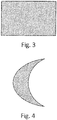
FIG. 3 is a cross-section of a magnetic component. -
FIG. 4 is a cross-section of an alternative magnetic component. - The present invention is directed to particles for use as a feedstock for manufacturing magnetic components. The particles include a magnetic core coated with an aluminum-silicon alloy. The particles can further include an optional outer silicon coating. The particles can be included in a feedstock used to produce a magnetic component. An aluminum alloy powder can be added to the feedstock to enhance an aluminum matrix surrounding the fused particles. The resulting components have a more robust microstructure and can be formed with more complex geometries than those produced using current manufacturing methods and materials.
-
FIG. 1 is an enlarged cross-section ofmagnetic particle 10.Particle 10 includesmagnetic core 12 and aluminum-silicon coating 14 surroundingcore 12.Particle 10, as shown, also includes coating 16, although exemplary embodiments ofparticle 10 do not require coating 16.Core 12 is formed from a sintered powder of magnetic material. The material can be a permanent magnetic material formed from rare earth elements. For example,core 12 can be formed from an alloy of samarium or neodymium. Other suitable permanent magnet materials, such as ceramics, ferrites, and manganese bismuth are contemplated herein. -
Coating 14 is an aluminum alloy of a composition that is considered suitable for welding added to enhance the material properties ofparticle 10. For example, such alloys experience less solidification cracking than other materials. Suitable alloys forcoating 14 can be Al12Si, AlSi10Mg, Aluminum 356.0, or Aluminum 357.0, to name a few, non-limiting examples. Other alloys, such as a 6000 series aluminum alloy, are contemplated herein.Coating 14 has low magnetic permeability (µ) compared tocore 12, such thatcoating 14 does not interfere with a magnetic field generated withincore 12. -
Coating 14 can be applied to core(s) 12 using a fluidized bed powder coating process, during whichheated cores 12 are immersed in a container of an aluminum-silicon alloy powder, or are passed through a cloud of electrically charged powder.Coating 14 can alternatively be applied using a mechanical dry coating process, such as ball milling. Other suitable coating techniques are contemplated herein. -
Coating 16 is a silicon-based coating that can be applied to increase the silicon content ofparticle 10. For example, a 6000 series aluminum alloy has a lower silicon content (compared to other coating 14 materials), so an embodiment using such an alloy forcoating 14 can benefit from the addition of coating 16.Coating 16 can be applied using one of the methods described above with respect to coating 14. Alternatively,coating 16 can be applied using a chemical vapor deposition (CVD) process.Coatings 14 and/or 16 can, but do not always, coat the entire surface ofcore 12/coating 14. The extent to which eachcoating 14 and/or 16 covers the underlying surface will depend on, for example, surface imperfections or the coating process used. -
Particle 10 can have a spherical or near-spherical shape in order to optimize particle packing when forming a component.Particle 10 can have a diameter (d) ranging from 15 µm to 150 µm. The diameter can range from 40 µm to 45 µm in an exemplary embodiment. The diameter ofparticle 10 depends on such factors as the number and thickness of coatings applied overcore 12, or the build parameters for the desired component. -
FIG. 2 is a magnified, three-dimensional cross-section showing a portion ofmagnetic component 18, formed as an aluminum metal matrix composite. As can be seen inFIG. 2 ,particles 10 are contained withinmatrix 20.Matrix 20 is an aluminum matrix that can be formed by adding a supplemental aluminum powder material to thefeedstock containing particles 10. It is also considered that the supplemental aluminum powder can be introduced intocomponent 18 separately, but concurrent withparticles 10. The supplemental powder material can be formed from an aluminum alloy, such as the aluminum-silicon alloys used to formcoating 14. Other suitable aluminum alloys are contemplated herein. - The density (p) of component 18 (the number or
particles 10 per cubic volume) can be tailored depending on the requirements ofcomponent 18. Density can range from, for example, 25% to 74%, depending on factors such as particle distribution and size, as well as the magnetic material used and the magnetic field requirements ofcomponent 18. For example, ifcomponent 18 needs only to be weakly magnetic, it can be made to be less dense than components for other applications. In an exemplary embodiment,particles 10 can be of uniform size and distribution. In other embodiments, however,particles 10 can be arranged in a less ordered fashion, and/or can vary in size, depending on the desired mechanical properties or the manufacturing process used. -
Component 18 can be formed using a powder-based, directed energy deposition process, using a feedstock ofparticles 10 and the supplemental aluminum alloy powder. The feedstock is deposited as a thin layer onto a build substrate, and a laser (or other energy source) fuses the layer. The process is repeated to formcomponent 18.Component 18 can be formed to have various geometries, and can include straight or curved sides. For example, a cross-sectional shape ofcomponent 10 can be rectangular or crescent shaped, as is shown inFIGS. 3 and 4 , respectively. Other cross-sectional shapes, such as a circle, ellipse, star, or polygon are contemplated herein.Component 18 can undergo post-manufacturing machining to smooth edges, create surface enhancements, etc. Finally,component 18 can be magnetized using an electric current.Component 18 can be incorporated into, for example, a permanent magnetic generator. - The disclosed particles can be used to form components having improved mechanical properties, and can allow for the manufacture of components having complex geometries. The disclosed components can be used in a variety of applications, including aerospace, automotive, and other transportation industries.
- The following are non-exclusive descriptions of possible embodiments of the present invention.
- A particle for use in a powder-based additive manufacturing process includes a magnetic core having a first magnetic permeability, and an aluminum alloy coating surrounding the magnetic core. The aluminum alloy coating has a second magnetic permeability lower than the first magnetic permeability.
- The particle of the preceding paragraph can optionally include, additionally and/or alternatively, any one or more of the following features, configurations and/or additional components:
- The above particle can further include a silicon-based coating surrounding the aluminum alloy coating.
- In any of the above particles, the magnetic particle can have a spherical or near-spherical shape.
- In any of the above particles, a particle diameter can range from 15 µm to 150 µm.
- In any of the above particles, a particle diameter can range from 40 µm to 45 µm.
- In any of the above particles, the magnetic core can be formed from a permanent magnetic material.
- In any of the above particles, the permanent magnetic material can include a rare earth element.
- In any of the above particles, the aluminum alloy coating can include a material selected from the group consisting of Al12Si, AlSi10Mg, C356, C357, and combinations thereof.
- A three-dimensional magnetic component includes an aluminum alloy matrix, and a plurality of particles dispersed throughout the matrix. Each of the particles includes a magnetic core having a first magnetic permeability, and an aluminum alloy coating surrounding the magnetic core. The aluminum alloy coating has a second magnetic permeability lower than the first magnetic permeability.
- In the above component, a density of the particles within the matrix can range from 25% to 74%.
- In any of the above components, the aluminum alloy matrix and the aluminum alloy coating can be formed from the same material.
- Any of the above components can further include a silicon-based coating surrounding the aluminum alloy coating.
- In any of the above components, a cross-sectional shape of the component can include a straight portion.
- In any of the above components, a cross-sectional shape of the component can include a curved portion.
- A method of making a three-dimensional magnetic component includes applying a layer of a feedstock to a build substrate, and fusing the layer using an energy source. The feedstock includes a plurality of magnetic particles having a permanent magnetic core and an aluminum alloy coating surrounding the permanent magnetic core.
- The above method can further include repeating the steps of applying the layer and fusing the layer to form the three-dimensional component.
- Any of the above methods can further include machining the three-dimensional component.
- Any of the above methods can further include magnetizing the three-dimensional component using an electric current.
- In any of the above methods, the feedstock can further include an aluminum alloy powder.
- In any of the above methods, each of the particles can further include a silicon-based coating surrounding the aluminum alloy coating.
- While the invention has been described with reference to an exemplary embodiment(s), it will be understood by those skilled in the art that various changes may be made and equivalents may be substituted for elements thereof without departing from the scope of the invention. In addition, many modifications may be made to adapt a particular situation or material to the teachings of the invention without departing from the essential scope thereof. Therefore, it is intended that the invention not be limited to the particular embodiment(s) disclosed, but that the invention will include all embodiments falling within the scope of the appended claims.
Claims (15)
- A particle (10) for use in a powder-based additive manufacturing process comprising:a magnetic core (12) having a first magnetic permeability; andan aluminum alloy coating (14) surrounding the magnetic core (12), the aluminum alloy coating (14) having a second magnetic permeability lower than the first magnetic permeability.
- The particle of claim 1 and further comprising: a silicon-based coating (16) surrounding the aluminum alloy coating.
- The particle of claim 1, wherein the magnetic particle (10) has a spherical or near-spherical shape.
- The particle of claim 3, wherein a particle diameter ranges from 15 µm to 150 µm, and preferably wherein a particle diameter ranges from 40 µm to 45 µm.
- The particle of any preceding claim, wherein the magnetic core (12) is formed from a permanent magnetic material, and preferablywherein the permanent magnetic material comprises a rare earth element.
- The particle of any preceding claim, wherein the aluminum alloy coating (14) comprises a material selected from the group consisting of Al12Si, AlSi10Mg, C356, C357, and combinations thereof.
- A three-dimensional magnetic component comprising:an aluminum alloy matrix; anda plurality of particles (10) dispersed throughout the matrix, each of the particles comprising:a magnetic core (12) having a first magnetic permeability; andan aluminum alloy coating (14) surrounding the magnetic core (12), the aluminum alloy coating (14) having a second magnetic permeability lower than the first magnetic permeability.
- The component of claim 7, wherein a density of the particles within the matrix ranges from 25% to 74%.
- The component of claim 7 or 8, wherein the aluminum alloy matrix and the aluminum alloy coating are formed from the same material.
- The component of claim 7, 8 or 9 and further comprising: a silicon-based coating surrounding the aluminum alloy coating.
- The component of claim 7, 8, 9 or 10 wherein a cross-sectional shape of the component has a straight portion, or wherein a cross-sectional shape of the component has a curved portion.
- A method of making a three-dimensional magnetic component, the method comprising:applying a layer of a feedstock to a build substrate, the feedstock comprising a plurality of particles (10), each of the particles (10) comprising a permanent magnetic core (12) and an aluminum alloy coating (14) surrounding the permanent magnetic core (12); andfusing the layer using an energy source.
- The method of claim 12 and further comprising: repeating the steps of applying the layer and fusing the layer to form the three-dimensional component, and preferablyfurther comprising: machining the three-dimensional component, and/orfurther comprising: magnetizing the three-dimensional component using an electric current.
- The method of claim 12 or 13, wherein the feedstock further includes an aluminum alloy powder.
- The method of claim 12, 13 or 14, wherein each of the particles (10) further comprises a silicon-based coating surrounding the aluminum alloy coating (14).
Applications Claiming Priority (1)
| Application Number | Priority Date | Filing Date | Title |
|---|---|---|---|
| US15/837,770 US20190180896A1 (en) | 2017-12-11 | 2017-12-11 | Aluminum alloy particle with a permanent magnet core |
Publications (2)
| Publication Number | Publication Date |
|---|---|
| EP3495076A1 true EP3495076A1 (en) | 2019-06-12 |
| EP3495076B1 EP3495076B1 (en) | 2021-03-24 |
Family
ID=64650226
Family Applications (1)
| Application Number | Title | Priority Date | Filing Date |
|---|---|---|---|
| EP18210679.9A Active EP3495076B1 (en) | 2017-12-11 | 2018-12-06 | Aluminum alloy particle with a permanent magnet core |
Country Status (2)
| Country | Link |
|---|---|
| US (1) | US20190180896A1 (en) |
| EP (1) | EP3495076B1 (en) |
Citations (2)
| Publication number | Priority date | Publication date | Assignee | Title |
|---|---|---|---|---|
| EP0056257A1 (en) * | 1981-01-10 | 1982-07-21 | Hitachi Maxell Ltd. | Method for production of metal magnetic particles |
| JP2000046073A (en) * | 1998-07-28 | 2000-02-15 | Mitsubishi Electric Corp | Magnetic powder for magnetic particle type electromagnetic coupling device and method for producing the same |
-
2017
- 2017-12-11 US US15/837,770 patent/US20190180896A1/en not_active Abandoned
-
2018
- 2018-12-06 EP EP18210679.9A patent/EP3495076B1/en active Active
Patent Citations (2)
| Publication number | Priority date | Publication date | Assignee | Title |
|---|---|---|---|---|
| EP0056257A1 (en) * | 1981-01-10 | 1982-07-21 | Hitachi Maxell Ltd. | Method for production of metal magnetic particles |
| JP2000046073A (en) * | 1998-07-28 | 2000-02-15 | Mitsubishi Electric Corp | Magnetic powder for magnetic particle type electromagnetic coupling device and method for producing the same |
Also Published As
| Publication number | Publication date |
|---|---|
| EP3495076B1 (en) | 2021-03-24 |
| US20190180896A1 (en) | 2019-06-13 |
Similar Documents
| Publication | Publication Date | Title |
|---|---|---|
| JP7499380B2 (en) | motor | |
| EP3260223A1 (en) | Structured powder particles for feedstock improvement for laser based additive manufacturing | |
| US11180841B2 (en) | Structures utilizing a structured magnetic material and methods for making | |
| WO1990002604A1 (en) | Moldable microcapsule with high percentage solid and method of manufacture | |
| Khoshnevis et al. | Metallic part fabrication using selective inhibition sintering (SIS) | |
| US12199469B2 (en) | Material with directional microstructure | |
| JP2016162764A (en) | Magnetic powder mixed resin material | |
| EP3495076B1 (en) | Aluminum alloy particle with a permanent magnet core | |
| JP5304908B2 (en) | Manufacturing method of dust core | |
| US20250316410A1 (en) | Reduced Common Mode Voltage Pulse Width Modulation Switching Scheme with Capacitor Voltage Balancing for a Multilevel Power Converter | |
| Gwak et al. | Optimization of laser‐powder bed fusion processed Fe–4.5 Si alloy via response surface methodology | |
| CN113796001B (en) | Magnetic sheet stack, method for manufacturing magnetic sheet stack and motor | |
| JP2009290024A (en) | Method for manufacturing pressed powder magnetic core | |
| US20190006098A1 (en) | Near net shape manufacturing of magnets | |
| JP4818722B2 (en) | Manufacturing method of NdFeB-based sintered magnet and mold for manufacturing NdFeB-based sintered magnet | |
| CN113454739B (en) | Method for producing self-magnetizing net-shape permanent magnet by additive manufacturing | |
| JP2008294469A (en) | METHOD OF MANUFACTURING NdFeB-BASED SINTERED MAGNET, AND MOLD FOR MANUFACTURING NdFeB-BASED SINTERED MAGNET | |
| WO2018186006A1 (en) | Compressed powder magnetic core and magnetic core powder, and production method therefor | |
| Jiang et al. | Study on the microstructure and wear/corrosion resistance of WC-10Co4Cr coating deposited by high velocity oxy-fuel | |
| Suen | Electrical Steel Fabricated by Binder Jet Printing | |
| JP2007129093A (en) | Soft magnetic material and dust core produced using the same | |
| CN121620850A (en) | Manufacturing method, rotating electrical machine, and electromagnetic steel sheet | |
| CN116206849A (en) | Additive manufacturing of ND-FE-B magnets with insulating layer | |
| CN116598112A (en) | Dual-phase soft magnetic particle combinations, components and methods of manufacture | |
| GB2557186A (en) | Nanoparticle coating method |
Legal Events
| Date | Code | Title | Description |
|---|---|---|---|
| PUAI | Public reference made under article 153(3) epc to a published international application that has entered the european phase |
Free format text: ORIGINAL CODE: 0009012 |
|
| STAA | Information on the status of an ep patent application or granted ep patent |
Free format text: STATUS: THE APPLICATION HAS BEEN PUBLISHED |
|
| AK | Designated contracting states |
Kind code of ref document: A1 Designated state(s): AL AT BE BG CH CY CZ DE DK EE ES FI FR GB GR HR HU IE IS IT LI LT LU LV MC MK MT NL NO PL PT RO RS SE SI SK SM TR |
|
| AX | Request for extension of the european patent |
Extension state: BA ME |
|
| STAA | Information on the status of an ep patent application or granted ep patent |
Free format text: STATUS: REQUEST FOR EXAMINATION WAS MADE |
|
| 17P | Request for examination filed |
Effective date: 20191211 |
|
| RBV | Designated contracting states (corrected) |
Designated state(s): AL AT BE BG CH CY CZ DE DK EE ES FI FR GB GR HR HU IE IS IT LI LT LU LV MC MK MT NL NO PL PT RO RS SE SI SK SM TR |
|
| STAA | Information on the status of an ep patent application or granted ep patent |
Free format text: STATUS: EXAMINATION IS IN PROGRESS |
|
| 17Q | First examination report despatched |
Effective date: 20200415 |
|
| RIC1 | Information provided on ipc code assigned before grant |
Ipc: B22F 1/02 20060101AFI20200901BHEP Ipc: B22F 3/105 20060101ALI20200901BHEP Ipc: H01F 1/06 20060101ALI20200901BHEP Ipc: B33Y 70/00 20200101ALI20200901BHEP Ipc: H01F 1/08 20060101ALI20200901BHEP Ipc: B33Y 80/00 20150101ALI20200901BHEP Ipc: B29C 64/153 20170101ALI20200901BHEP Ipc: H01F 1/053 20060101ALI20200901BHEP Ipc: H01F 41/02 20060101ALI20200901BHEP |
|
| GRAP | Despatch of communication of intention to grant a patent |
Free format text: ORIGINAL CODE: EPIDOSNIGR1 |
|
| STAA | Information on the status of an ep patent application or granted ep patent |
Free format text: STATUS: GRANT OF PATENT IS INTENDED |
|
| INTG | Intention to grant announced |
Effective date: 20201021 |
|
| GRAS | Grant fee paid |
Free format text: ORIGINAL CODE: EPIDOSNIGR3 |
|
| GRAA | (expected) grant |
Free format text: ORIGINAL CODE: 0009210 |
|
| STAA | Information on the status of an ep patent application or granted ep patent |
Free format text: STATUS: THE PATENT HAS BEEN GRANTED |
|
| AK | Designated contracting states |
Kind code of ref document: B1 Designated state(s): AL AT BE BG CH CY CZ DE DK EE ES FI FR GB GR HR HU IE IS IT LI LT LU LV MC MK MT NL NO PL PT RO RS SE SI SK SM TR |
|
| REG | Reference to a national code |
Ref country code: GB Ref legal event code: FG4D |
|
| REG | Reference to a national code |
Ref country code: CH Ref legal event code: EP |
|
| REG | Reference to a national code |
Ref country code: IE Ref legal event code: FG4D |
|
| REG | Reference to a national code |
Ref country code: AT Ref legal event code: REF Ref document number: 1373981 Country of ref document: AT Kind code of ref document: T Effective date: 20210415 Ref country code: DE Ref legal event code: R096 Ref document number: 602018014329 Country of ref document: DE |
|
| REG | Reference to a national code |
Ref country code: LT Ref legal event code: MG9D |
|
| PG25 | Lapsed in a contracting state [announced via postgrant information from national office to epo] |
Ref country code: NO Free format text: LAPSE BECAUSE OF FAILURE TO SUBMIT A TRANSLATION OF THE DESCRIPTION OR TO PAY THE FEE WITHIN THE PRESCRIBED TIME-LIMIT Effective date: 20210624 Ref country code: BG Free format text: LAPSE BECAUSE OF FAILURE TO SUBMIT A TRANSLATION OF THE DESCRIPTION OR TO PAY THE FEE WITHIN THE PRESCRIBED TIME-LIMIT Effective date: 20210624 Ref country code: HR Free format text: LAPSE BECAUSE OF FAILURE TO SUBMIT A TRANSLATION OF THE DESCRIPTION OR TO PAY THE FEE WITHIN THE PRESCRIBED TIME-LIMIT Effective date: 20210324 Ref country code: FI Free format text: LAPSE BECAUSE OF FAILURE TO SUBMIT A TRANSLATION OF THE DESCRIPTION OR TO PAY THE FEE WITHIN THE PRESCRIBED TIME-LIMIT Effective date: 20210324 Ref country code: GR Free format text: LAPSE BECAUSE OF FAILURE TO SUBMIT A TRANSLATION OF THE DESCRIPTION OR TO PAY THE FEE WITHIN THE PRESCRIBED TIME-LIMIT Effective date: 20210625 |
|
| PG25 | Lapsed in a contracting state [announced via postgrant information from national office to epo] |
Ref country code: SE Free format text: LAPSE BECAUSE OF FAILURE TO SUBMIT A TRANSLATION OF THE DESCRIPTION OR TO PAY THE FEE WITHIN THE PRESCRIBED TIME-LIMIT Effective date: 20210324 Ref country code: LV Free format text: LAPSE BECAUSE OF FAILURE TO SUBMIT A TRANSLATION OF THE DESCRIPTION OR TO PAY THE FEE WITHIN THE PRESCRIBED TIME-LIMIT Effective date: 20210324 Ref country code: RS Free format text: LAPSE BECAUSE OF FAILURE TO SUBMIT A TRANSLATION OF THE DESCRIPTION OR TO PAY THE FEE WITHIN THE PRESCRIBED TIME-LIMIT Effective date: 20210324 |
|
| REG | Reference to a national code |
Ref country code: NL Ref legal event code: MP Effective date: 20210324 |
|
| REG | Reference to a national code |
Ref country code: AT Ref legal event code: MK05 Ref document number: 1373981 Country of ref document: AT Kind code of ref document: T Effective date: 20210324 |
|
| PG25 | Lapsed in a contracting state [announced via postgrant information from national office to epo] |
Ref country code: NL Free format text: LAPSE BECAUSE OF FAILURE TO SUBMIT A TRANSLATION OF THE DESCRIPTION OR TO PAY THE FEE WITHIN THE PRESCRIBED TIME-LIMIT Effective date: 20210324 |
|
| PG25 | Lapsed in a contracting state [announced via postgrant information from national office to epo] |
Ref country code: AT Free format text: LAPSE BECAUSE OF FAILURE TO SUBMIT A TRANSLATION OF THE DESCRIPTION OR TO PAY THE FEE WITHIN THE PRESCRIBED TIME-LIMIT Effective date: 20210324 Ref country code: SM Free format text: LAPSE BECAUSE OF FAILURE TO SUBMIT A TRANSLATION OF THE DESCRIPTION OR TO PAY THE FEE WITHIN THE PRESCRIBED TIME-LIMIT Effective date: 20210324 Ref country code: LT Free format text: LAPSE BECAUSE OF FAILURE TO SUBMIT A TRANSLATION OF THE DESCRIPTION OR TO PAY THE FEE WITHIN THE PRESCRIBED TIME-LIMIT Effective date: 20210324 Ref country code: CZ Free format text: LAPSE BECAUSE OF FAILURE TO SUBMIT A TRANSLATION OF THE DESCRIPTION OR TO PAY THE FEE WITHIN THE PRESCRIBED TIME-LIMIT Effective date: 20210324 Ref country code: EE Free format text: LAPSE BECAUSE OF FAILURE TO SUBMIT A TRANSLATION OF THE DESCRIPTION OR TO PAY THE FEE WITHIN THE PRESCRIBED TIME-LIMIT Effective date: 20210324 |
|
| REG | Reference to a national code |
Ref country code: DE Ref legal event code: R079 Ref document number: 602018014329 Country of ref document: DE Free format text: PREVIOUS MAIN CLASS: B22F0001020000 Ipc: B22F0001000000 |
|
| PG25 | Lapsed in a contracting state [announced via postgrant information from national office to epo] |
Ref country code: IS Free format text: LAPSE BECAUSE OF FAILURE TO SUBMIT A TRANSLATION OF THE DESCRIPTION OR TO PAY THE FEE WITHIN THE PRESCRIBED TIME-LIMIT Effective date: 20210724 Ref country code: PL Free format text: LAPSE BECAUSE OF FAILURE TO SUBMIT A TRANSLATION OF THE DESCRIPTION OR TO PAY THE FEE WITHIN THE PRESCRIBED TIME-LIMIT Effective date: 20210324 Ref country code: PT Free format text: LAPSE BECAUSE OF FAILURE TO SUBMIT A TRANSLATION OF THE DESCRIPTION OR TO PAY THE FEE WITHIN THE PRESCRIBED TIME-LIMIT Effective date: 20210726 Ref country code: SK Free format text: LAPSE BECAUSE OF FAILURE TO SUBMIT A TRANSLATION OF THE DESCRIPTION OR TO PAY THE FEE WITHIN THE PRESCRIBED TIME-LIMIT Effective date: 20210324 Ref country code: RO Free format text: LAPSE BECAUSE OF FAILURE TO SUBMIT A TRANSLATION OF THE DESCRIPTION OR TO PAY THE FEE WITHIN THE PRESCRIBED TIME-LIMIT Effective date: 20210324 |
|
| REG | Reference to a national code |
Ref country code: DE Ref legal event code: R097 Ref document number: 602018014329 Country of ref document: DE |
|
| PG25 | Lapsed in a contracting state [announced via postgrant information from national office to epo] |
Ref country code: ES Free format text: LAPSE BECAUSE OF FAILURE TO SUBMIT A TRANSLATION OF THE DESCRIPTION OR TO PAY THE FEE WITHIN THE PRESCRIBED TIME-LIMIT Effective date: 20210324 Ref country code: DK Free format text: LAPSE BECAUSE OF FAILURE TO SUBMIT A TRANSLATION OF THE DESCRIPTION OR TO PAY THE FEE WITHIN THE PRESCRIBED TIME-LIMIT Effective date: 20210324 Ref country code: AL Free format text: LAPSE BECAUSE OF FAILURE TO SUBMIT A TRANSLATION OF THE DESCRIPTION OR TO PAY THE FEE WITHIN THE PRESCRIBED TIME-LIMIT Effective date: 20210324 |
|
| PLBE | No opposition filed within time limit |
Free format text: ORIGINAL CODE: 0009261 |
|
| STAA | Information on the status of an ep patent application or granted ep patent |
Free format text: STATUS: NO OPPOSITION FILED WITHIN TIME LIMIT |
|
| PG25 | Lapsed in a contracting state [announced via postgrant information from national office to epo] |
Ref country code: SI Free format text: LAPSE BECAUSE OF FAILURE TO SUBMIT A TRANSLATION OF THE DESCRIPTION OR TO PAY THE FEE WITHIN THE PRESCRIBED TIME-LIMIT Effective date: 20210324 |
|
| 26N | No opposition filed |
Effective date: 20220104 |
|
| PG25 | Lapsed in a contracting state [announced via postgrant information from national office to epo] |
Ref country code: IS Free format text: LAPSE BECAUSE OF FAILURE TO SUBMIT A TRANSLATION OF THE DESCRIPTION OR TO PAY THE FEE WITHIN THE PRESCRIBED TIME-LIMIT Effective date: 20210724 |
|
| PG25 | Lapsed in a contracting state [announced via postgrant information from national office to epo] |
Ref country code: MC Free format text: LAPSE BECAUSE OF FAILURE TO SUBMIT A TRANSLATION OF THE DESCRIPTION OR TO PAY THE FEE WITHIN THE PRESCRIBED TIME-LIMIT Effective date: 20210324 |
|
| REG | Reference to a national code |
Ref country code: CH Ref legal event code: PL |
|
| REG | Reference to a national code |
Ref country code: BE Ref legal event code: MM Effective date: 20211231 |
|
| PG25 | Lapsed in a contracting state [announced via postgrant information from national office to epo] |
Ref country code: LU Free format text: LAPSE BECAUSE OF NON-PAYMENT OF DUE FEES Effective date: 20211206 Ref country code: IE Free format text: LAPSE BECAUSE OF NON-PAYMENT OF DUE FEES Effective date: 20211206 |
|
| PG25 | Lapsed in a contracting state [announced via postgrant information from national office to epo] |
Ref country code: BE Free format text: LAPSE BECAUSE OF NON-PAYMENT OF DUE FEES Effective date: 20211231 |
|
| PG25 | Lapsed in a contracting state [announced via postgrant information from national office to epo] |
Ref country code: LI Free format text: LAPSE BECAUSE OF NON-PAYMENT OF DUE FEES Effective date: 20211231 Ref country code: CH Free format text: LAPSE BECAUSE OF NON-PAYMENT OF DUE FEES Effective date: 20211231 |
|
| PG25 | Lapsed in a contracting state [announced via postgrant information from national office to epo] |
Ref country code: IT Free format text: LAPSE BECAUSE OF FAILURE TO SUBMIT A TRANSLATION OF THE DESCRIPTION OR TO PAY THE FEE WITHIN THE PRESCRIBED TIME-LIMIT Effective date: 20210324 |
|
| P01 | Opt-out of the competence of the unified patent court (upc) registered |
Effective date: 20230522 |
|
| PG25 | Lapsed in a contracting state [announced via postgrant information from national office to epo] |
Ref country code: CY Free format text: LAPSE BECAUSE OF FAILURE TO SUBMIT A TRANSLATION OF THE DESCRIPTION OR TO PAY THE FEE WITHIN THE PRESCRIBED TIME-LIMIT Effective date: 20210324 |
|
| PG25 | Lapsed in a contracting state [announced via postgrant information from national office to epo] |
Ref country code: HU Free format text: LAPSE BECAUSE OF FAILURE TO SUBMIT A TRANSLATION OF THE DESCRIPTION OR TO PAY THE FEE WITHIN THE PRESCRIBED TIME-LIMIT; INVALID AB INITIO Effective date: 20181206 |
|
| PG25 | Lapsed in a contracting state [announced via postgrant information from national office to epo] |
Ref country code: MK Free format text: LAPSE BECAUSE OF FAILURE TO SUBMIT A TRANSLATION OF THE DESCRIPTION OR TO PAY THE FEE WITHIN THE PRESCRIBED TIME-LIMIT Effective date: 20210324 |
|
| PG25 | Lapsed in a contracting state [announced via postgrant information from national office to epo] |
Ref country code: MT Free format text: LAPSE BECAUSE OF FAILURE TO SUBMIT A TRANSLATION OF THE DESCRIPTION OR TO PAY THE FEE WITHIN THE PRESCRIBED TIME-LIMIT Effective date: 20210324 |
|
| PG25 | Lapsed in a contracting state [announced via postgrant information from national office to epo] |
Ref country code: TR Free format text: LAPSE BECAUSE OF FAILURE TO SUBMIT A TRANSLATION OF THE DESCRIPTION OR TO PAY THE FEE WITHIN THE PRESCRIBED TIME-LIMIT Effective date: 20210324 |
|
| PGFP | Annual fee paid to national office [announced via postgrant information from national office to epo] |
Ref country code: DE Payment date: 20251126 Year of fee payment: 8 |
|
| PGFP | Annual fee paid to national office [announced via postgrant information from national office to epo] |
Ref country code: GB Payment date: 20251119 Year of fee payment: 8 |
|
| PGFP | Annual fee paid to national office [announced via postgrant information from national office to epo] |
Ref country code: FR Payment date: 20251119 Year of fee payment: 8 |