EP3495029B1 - Modular extraction tower - Google Patents
Modular extraction tower Download PDFInfo
- Publication number
- EP3495029B1 EP3495029B1 EP16911721.5A EP16911721A EP3495029B1 EP 3495029 B1 EP3495029 B1 EP 3495029B1 EP 16911721 A EP16911721 A EP 16911721A EP 3495029 B1 EP3495029 B1 EP 3495029B1
- Authority
- EP
- European Patent Office
- Prior art keywords
- column
- module
- support
- modules
- coupled
- Prior art date
- Legal status (The legal status is an assumption and is not a legal conclusion. Google has not performed a legal analysis and makes no representation as to the accuracy of the status listed.)
- Active
Links
Images




Classifications
-
- B—PERFORMING OPERATIONS; TRANSPORTING
- B01—PHYSICAL OR CHEMICAL PROCESSES OR APPARATUS IN GENERAL
- B01D—SEPARATION
- B01D11/00—Solvent extraction
- B01D11/04—Solvent extraction of solutions which are liquid
- B01D11/0426—Counter-current multistage extraction towers in a vertical or sloping position
- B01D11/043—Counter-current multistage extraction towers in a vertical or sloping position with stationary contacting elements, sieve plates or loose contacting elements
-
- B—PERFORMING OPERATIONS; TRANSPORTING
- B01—PHYSICAL OR CHEMICAL PROCESSES OR APPARATUS IN GENERAL
- B01D—SEPARATION
- B01D11/00—Solvent extraction
- B01D11/04—Solvent extraction of solutions which are liquid
-
- B—PERFORMING OPERATIONS; TRANSPORTING
- B01—PHYSICAL OR CHEMICAL PROCESSES OR APPARATUS IN GENERAL
- B01D—SEPARATION
- B01D11/00—Solvent extraction
- B01D11/04—Solvent extraction of solutions which are liquid
- B01D11/0426—Counter-current multistage extraction towers in a vertical or sloping position
Definitions
- the present invention relates to a modular extraction column.
- An extraction column is used in a variety of chemical plants, as major equipment in an extraction process.
- the extraction column performs extraction by allowing a heavy phase of higher density to be input into a top head thereof to flow downwards while allowing a light phase of lower density to be input into a bottom head thereof, such that the two phases continuously come into countercurrent contact.
- Such extraction columns are fabricated in a variety of diameters and heights according to the properties of fluid in processes. Inner structures having a variety of shapes may be added to increase the contact area between fluids as required.
- Korean Patent No. 10-1522771 (patented on May 26, 2015 ) disclosed a vertical liquid-liquid separation apparatus based on the principle of a mixer-settler apparatus.
- the disclosed apparatus has superior acid/base resistance, with parts thereof being able to be easily operated.
- a typical extraction column as disclosed in the prior-art document has an integrated structure, in which the height of the column is determined using a specific standard, such as height of transfer unit (HTU) and number of transfer unit (NTU).
- HTU height of transfer unit
- NTU number of transfer unit
- the present invention has been made keeping in mind the above problems occurring in the related art, and the present invention is intended to propose a modular extraction column that can be easily fabricated and constructed, and after construction, allows for easy maintenance, such as replacement of a damaged structural part and removal of contaminants.
- the modular extraction column facilitates the assembly and construction thereof, since the modular extraction column includes the end blocks and the body block consisting of the column modules.
- the inner structure is provided the shape of a cartridge for each column module and the cover is provided in the open area of the column module. It is therefore easy attach or detach the inner structure to or from the column module, thereby advantageously facilitating maintenance, such as replacement of a damaged portion of the inner structure or removal of contaminants.
- the body block 20 is a multi-stage structure, with both ends thereof being coupled to the flanges 110 of the end blocks 10 in a surface contact manner.
- the body block 20 includes column modules 210 and covers 220.
- the body block 20 is formed by stacking the column modules 210 having a predetermined length on one another, instead of having an integrated structure.
- each column module 210 includes a first module flange 212 and a second module flange 213.
- An accommodating portion 211 having a predetermined area is formed within the column module 210.
- the column module 210 has an open area 214 in one side. The open area 214 is able to communicate with the accommodating portion 211 within the column module 210.
- the length of the column module 210 may be adjusted considering the ease of manufacturing, fabrication, and maintenance according to the space of construction.
- the first module flange 212 and the second module flange 213 are provided coaxially on the opposite ends of the column module 210 to face away from each other.
- the first module flange 212 and the second module flange 213 may be arranged to abut against one or both of the flanges 110 of the end blocks 10 or the second module flange 213 and the first module flange 212 of the adjacent other column modules 210 to be coupled thereto in extended areas.
- the dimensions, shape, and size of the first module flange 212 are the same as those of the second module flange 213 and, furthermore, the flange 110, such that the column module 210 can be disposed without being restricted in the orientation thereof.
- the end blocks 10 and the body block 20 can be coupled to each other using the flanges.
- the end blocks 10 and the body block 20 may be stacked on and coupled to each other via gaskets 40.
- the gaskets 40 are provided in connecting portions between the flanges 110 of the end block 10 and the first module flange(s) 212 and the second module flange(s) 213 of the body block 20, thereby preventing leakage in the connecting portions.
- FIGS. 5A to 5E are perspective assembled views schematically illustrating examples of the inner structure 310 according to the exemplary embodiment of the present invention.
- the internal structure 310 has the shape of a cartridge that is introduced through the open area 214 and is seated in the accommodating portion 211 adjacent to the open area 214.
- the internal structure 310 is accommodated in the accommodating portion(s) 211 of the body block(s) 20 and functions to distribute fluid, thereby increasing the contact area between fluids.
- the structural body 320 may be formed by stacking a plurality of structural sections having the same shape on one another in the top-bottom direction to distribute a fluid in order to increase the contact area between fluids.
- the structural body 320 may be fabricated as one of a structure including perforated plates 321, a structure including sieve trays 322, or a structure including baffle trays 323.
- a second embodiment of the inner structure 310 may include the support 330 and packing 340.
- the second embodiment of the inner structure 310 may further include a packing holding film 350.
- the support 330 may include a plurality of support plates 332, the edges of which are coupled to each other to form a rectangular horizontal cross-section, such that a hollow inner area is defined within the support plates 332.
- the packing 340 may be accommodated in the hollow inner area and may be coupled to the support 330.
- the packing holding film 350 may be a structure disposed on one or both sides of the support 330.
- the packing holding film 350 may allow fluids to pass therethrough while supporting packing 340 such that the packing 340 such is not drained by flows of fluid.
- the packing holding film 350 may a mesh structure having a predetermined size, this is not intended to be limiting.
- the first embodiment and the second embodiment of the inner structure 310 may be determined suitably according to process characteristics.
- the modular extraction column 1 disclosed with reference to FIGS. 1 to 5E is not limited to the specific length or shape but is only provided for a better understanding of the present invention to those skilled in the art to which the present invention belongs.
- modular extraction column 10 end block 110: flange 20: body block 210: module 211: accommodating portion 212: first module flange 213: second module flange 214: open area 220: cover 310: cartridge 321: perforated plate 322: sieve tray 323: baffle tray 331: support leg 332: support plate 340: packing 350: packing holding film 40: gasket
Landscapes
- Chemical & Material Sciences (AREA)
- Chemical Kinetics & Catalysis (AREA)
- Extraction Or Liquid Replacement (AREA)
- Treatment Of Liquids With Adsorbents In General (AREA)
- Physical Or Chemical Processes And Apparatus (AREA)
Description
- The present invention relates to a modular extraction column.
- An extraction column is used in a variety of chemical plants, as major equipment in an extraction process. The extraction column performs extraction by allowing a heavy phase of higher density to be input into a top head thereof to flow downwards while allowing a light phase of lower density to be input into a bottom head thereof, such that the two phases continuously come into countercurrent contact. Such extraction columns are fabricated in a variety of diameters and heights according to the properties of fluid in processes. Inner structures having a variety of shapes may be added to increase the contact area between fluids as required.
- As a prior-art document related to extraction column,
Korean Patent No. 10-1522771 (patented on May 26, 2015 - A typical extraction column as disclosed in the prior-art document has an integrated structure, in which the height of the column is determined using a specific standard, such as height of transfer unit (HTU) and number of transfer unit (NTU). Once the extraction column is constructed, it is difficult to disassemble the extraction column into pieces. It is therefore difficult to change the inner structure of the extraction column, replace a damaged structural part of the extraction column, or remove internal contaminants when considering process operations of the extraction column.
-
Korean Patent No. 10-1522771 (May 26, 2015 US 6 875 406 B1 (April 5, 2005 );US 1 749 266 A (March 4, 1930 );CN 201 643 778 U (November 24, 2010 );DE 37 27 481 A1 (March 2, 1989 );EP 2 796 190 A1 (October 29, 2014 ) . - Accordingly, the present invention has been made keeping in mind the above problems occurring in the related art, and the present invention is intended to propose a modular extraction column that can be easily fabricated and constructed, and after construction, allows for easy maintenance, such as replacement of a damaged structural part and removal of contaminants.
- In order to achieve the above object, according to one aspect of the present invention, a modular extraction column includes the features of
independent claim 1. - According to the present invention, the modular extraction column facilitates the assembly and construction thereof, since the modular extraction column includes the end blocks and the body block consisting of the column modules.
- In addition, according to the present invention, after the construction of the modular extraction column, it is possible to easily change the inner structure or the volume of the extraction column by changing the number of the column modules of the body block, which is advantageous.
- Furthermore, according to the present invention, the inner structure is provided the shape of a cartridge for each column module and the cover is provided in the open area of the column module. It is therefore easy attach or detach the inner structure to or from the column module, thereby advantageously facilitating maintenance, such as replacement of a damaged portion of the inner structure or removal of contaminants.
- In addition, according to the present invention, the cross-section of the modular extraction column in the direction perpendicular to the longitudinal direction is quadrangular (more particularly, rectangular) instead of being curved, thereby advantageously facilitating fabrication.
- The effects of the present invention are not limited to the above-described effects but the other effects will be apparent to those skilled in the art to which the present invention belongs from the specification and the accompanying drawings.
-
-
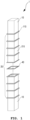
FIG. 1 is an assembly view schematically illustrating a modular extraction column according to an exemplary embodiment of the present invention; -
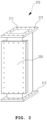
FIG. 2 is a perspective view illustrating a column module according to the exemplary embodiment of the present invention; -
FIG. 3A is a front elevation view illustrating the column module shown inFIG. 2 ; -
FIGS. 3B and 3C are cross-sectional views taken along lines A-A' and B-B' inFIG. 3A ; -
FIGS. 4A and 4B are front elevation views illustrating the column module and the cover according to the exemplary embodiment of the present invention; and -
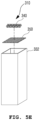
FIGS. 5A to 5E are perspective assembled views schematically illustrating examples of the inner structure according to the exemplary embodiment of the present invention. - Descriptions of specific structures and functions disclosed in the following embodiments of the present invention are only provided to render exemplary embodiments according to the concept of the present invention. The embodiments according to the concept of the present invention may be implemented in a variety of forms. In addition, it is to be understood that the present description is not intended to limit the present invention to those exemplary embodiments. On the contrary, the present invention is intended to cover not only the exemplary embodiments, but also various alternatives, modifications, equivalents, and substitution, that may be included within scope of the present invention, as defined by the appended claims.
- Hereinafter, the present invention will be described in detail with reference to the drawings. Herein, the same reference numerals will be used throughout the drawings to refer to the components having substantially the same functions.
-
FIG. 1 is an assembly view schematically illustrating a modular extraction column according to an exemplary embodiment of the present invention,FIG. 2 is a perspective view illustrating a column module according to the exemplary embodiment of the present invention,FIG. 3A is a front elevation view illustrating the column module shown inFIG. 2 , andFIGS. 3B and 3C are cross-sectional views taken along lines A-A' and B-B' inFIG. 3A . As illustrated inFIGS. 1 to 3C , themodular extraction column 1 includesend blocks 10, abody block 20, and inner structures. - The
end blocks 10 are disposed on both ends of themodular extraction column 1. Each of theend blocks 10 has a flange on one side, and is coupled to thebody block 20. - The
body block 20 is a multi-stage structure, with both ends thereof being coupled to theflanges 110 of theend blocks 10 in a surface contact manner. Thebody block 20 includescolumn modules 210 and covers 220. Thebody block 20 is formed by stacking thecolumn modules 210 having a predetermined length on one another, instead of having an integrated structure. - As illustrated in
FIGS. 2 ,3A to 3C , eachcolumn module 210 includes afirst module flange 212 and asecond module flange 213. Anaccommodating portion 211 having a predetermined area is formed within thecolumn module 210. In addition, thecolumn module 210 has anopen area 214 in one side. Theopen area 214 is able to communicate with theaccommodating portion 211 within thecolumn module 210. - The length of the
column module 210 may be adjusted considering the ease of manufacturing, fabrication, and maintenance according to the space of construction. - The
modular extraction column 1 according to the present embodiment as described above advantageously facilitates the assembly and construction thereof, since themodular extraction column 1 includes theend blocks 10 and thebody block 20 consisting of thecolumn modules 210. - In addition, after the construction of the modular extraction column, it is possible to easily change the inner structure or the volume of the extraction column by changing the number of the
column modules 210 of thebody block 20, which is advantageous. -
FIGS. 4A and 4B are front elevation views illustrating thecolumn module 210 and thecover 220 according to the exemplary embodiment of the present invention. As illustrated inFIGS. 4A and 4B , thecolumn module 210 further includes thecover 220. Thecover 220 has a shape and size covering theopen area 214 formed in one side of thecolumn module 210, and can be detachably coupled to the side of thecolumn module 210 to open and close theopen area 214. - The
cover 220 is detachably coupled to one side of thecolumn module 210, such that a coupling portion thereof forms a flange. Thecover 220 is coupled to thecolumn module 210 using bolts. Thecover 220 may further include agasket 40 to prevent leakage in the connecting portion between thecolumn module 210 and thecover 220. - Since the
column module 210 according to the present invention has thecover 220, it is possible to easily attach or detach aninner structure 310 to or from eachcolumn module 210 through theopen area 214. This advantageously facilitates maintenance, such as replacement of a damaged portion of theinner structure 310 or removal of contaminants. - The
first module flange 212 and thesecond module flange 213 are provided coaxially on the opposite ends of thecolumn module 210 to face away from each other. Thefirst module flange 212 and thesecond module flange 213 may be arranged to abut against one or both of theflanges 110 of the end blocks 10 or thesecond module flange 213 and thefirst module flange 212 of the adjacentother column modules 210 to be coupled thereto in extended areas. In this case, the dimensions, shape, and size of thefirst module flange 212 are the same as those of thesecond module flange 213 and, furthermore, theflange 110, such that thecolumn module 210 can be disposed without being restricted in the orientation thereof. Shortly, the end blocks 10 and thebody block 20 can be coupled to each other using the flanges. - The end blocks 10 and the
body block 20 may communicate with each other in the longitudinal direction while having quadrangular (more particularly, rectangular) cross-sections in the direction perpendicular to the longitudinal direction. In addition, theaccommodating portion 211 of thebody block 20 has a quadrangular (more particularly, rectangular) cross-section in the direction perpendicular to the longitudinal direction. - The end blocks 10 and the
body block 20 according to the embodiment of the present invention as described above have quadrangular (more particularly, rectangular) cross-sections in the direction perpendicular to the longitudinal direction. Since the quadrangular cross-section does not provide a curved surface, fabrication-involved operations, such as cutting or welding, are facilitated. - The end blocks 10 and the
body block 20 may be stacked on and coupled to each other viagaskets 40. Thegaskets 40 are provided in connecting portions between theflanges 110 of theend block 10 and the first module flange(s) 212 and the second module flange(s) 213 of thebody block 20, thereby preventing leakage in the connecting portions. -
FIGS. 5A to 5E are perspective assembled views schematically illustrating examples of theinner structure 310 according to the exemplary embodiment of the present invention. As illustrated inFIGS. 5A to 5E , theinternal structure 310 has the shape of a cartridge that is introduced through theopen area 214 and is seated in theaccommodating portion 211 adjacent to theopen area 214. Theinternal structure 310 is accommodated in the accommodating portion(s) 211 of the body block(s) 20 and functions to distribute fluid, thereby increasing the contact area between fluids. - A first embodiment of the
inner structure 310 includes a structural body 320 and a support 330. Theinner structure 310 is provided in eachcolumn module 210 of themodular extraction column 1. Theinner structure 310 may be fabricated separately from thecolumn module 210 to be coupled to the latter in order to increase the contact area between fluids. - In addition, the
inner structure 310 may be fabricated with an outer size that does not form a gap between theinner structure 310 and the inner surface of thecolumn module 210. Due to the quadrangular cross-sections, the modular extraction column according to the embodiment of the present invention can be easily fabricated, constructed, and assembled without leaving a gap between theinner structure 310 and thecolumn module 210, differently from common extraction column having circular cross-sections. Consequently, the modular extraction column according to the embodiment of the present invention is able to have higher efficiency. - The structural body 320 may be formed by stacking a plurality of structural sections having the same shape on one another in the top-bottom direction to distribute a fluid in order to increase the contact area between fluids. The structural body 320 may be fabricated as one of a structure including
perforated plates 321, a structure including sieve trays 322, or a structure includingbaffle trays 323. - The support 330 serves to support the structural body 320. When the structural body 320 is assembled by stacking the plurality of pieces on one another, the support 330 may be implemented as
support legs 331 orsupport plates 332. Thesupport legs 331 are coupled to the corners of the structural body 320 to support and fix the structural body 320. Thesupport plates 332 may be provided as two ormore support plates 332 to hold and fix the structural body 320. More specifically, thesupport plates 332 may be provided as a plurality of plates such that the edges of the plates are abutted against each other to form a rectangular horizontal cross-section. Alternatively, thesupport plates 332 may be implemented as a pair of right and left plates forming partitions, by which the structural body 320 is held and fixed. - The structural body 320 and the support 330 may be fabricated in a size that allows the structural body 320 and the support 330 to be disposed within the
accommodating portion 211 of thecolumn module 210. The structural body 320 and the support 330 may be coupled to each other using one, selected from among welding, rivets, bolts, and spline fitting, according to different process characteristics and fabrication convenience. - A second embodiment of the
inner structure 310 may include the support 330 and packing 340. In addition, the second embodiment of theinner structure 310 may further include apacking holding film 350. The support 330 may include a plurality ofsupport plates 332, the edges of which are coupled to each other to form a rectangular horizontal cross-section, such that a hollow inner area is defined within thesupport plates 332. The packing 340 may be accommodated in the hollow inner area and may be coupled to the support 330. - The
packing holding film 350 may be a structure disposed on one or both sides of the support 330. Thepacking holding film 350 may allow fluids to pass therethrough while supporting packing 340 such that the packing 340 such is not drained by flows of fluid. Although thepacking holding film 350 may a mesh structure having a predetermined size, this is not intended to be limiting. - The first embodiment and the second embodiment of the
inner structure 310 may be determined suitably according to process characteristics. - The
modular extraction column 1 disclosed with reference toFIGS. 1 to 5E is not limited to the specific length or shape but is only provided for a better understanding of the present invention to those skilled in the art to which the present invention belongs. - Although the exemplary embodiments of the present invention have been described for illustrative purposes, those skilled in the art will appreciate that various modifications, additions and substitutions are possible, without departing from the scope of the present invention as disclosed in the accompanying claims.
-
1: modular extraction column 10: end block 110: flange 20: body block 210: module 211: accommodating portion 212: first module flange 213: second module flange 214: open area 220: cover 310: cartridge 321: perforated plate 322: sieve tray 323: baffle tray 331: support leg 332: support plate 340: packing 350: packing holding film 40: gasket
Claims (7)
- A modular extraction column (1) comprising:end blocks (10) respectively having a flange (110) on one side;a body block (20) comprising a plurality of column modules (210) stacked on each other, the plurality of column modules (210) being coupled to the flanges (110) of the end blocks (10) in a surface contact manner, each of the plurality of column modules (210) comprising a first module flange (212) and a second module flange (213) provided on opposite ends and an accommodating portion (211) provided in an inner portion to have a predetermined area, wherein the plurality of column modules (210) are coupled to each other such that the first module flange (212) of one column module (210) among the plurality of column modules faces the second module flange (213) of an adjacent column module (210) among the plurality of column modules; andan inner structure (310) received in the accommodating portions (211) of the plurality of column modules (210) to distribute a fluid,characterized in that each of the plurality of column modules (210) have a quadrangular cross-section in a direction perpendicular to a longitudinal direction thereof and the end blocks (10) and the body block (20) communicate with each other, the accommodating portion (211) of each of the plurality of column modules (210) having a quadrangular cross-section in a direction perpendicular to a longitudinal direction thereof,wherein each of the plurality of column modules (2100 further comprises a cover (220) disposed adjacent to an open area (214) formed in one side of the each column module (210), the cover (220) being detachably coupled to a predetermined portion of the each column module (210) to open and close the open area (214),wherein the inner structure (310) comprises a cartridge (310) introduced through the open area (214) and seated in the accommodating portion (211) communicating with the open area (214).
- The modular extraction column (1) according to claim 1, wherein the end blocks (10) and the body block (20) are coupled to and stacked on each other such that the flanges (110) of the end blocks (10) are coupled to the first module flange (212) of a predetermined column module (210) among the plurality of column modules and the second module flange (213) of the opposite column module (210) among the plurality of column modules.
- The modular extraction column (10) according to claim 1, wherein the inner structure (310)comprises:a structural body formed of a plurality of structural sections having a predetermined shape and stacked in a top-bottom direction; anda support fixedly supporting the structural body.
- The modular extraction column (1) according to claim 3, wherein the structural body comprises one selected from the group consisting of perforated plates (321), sieve trays (322), and baffle trays (323).
- The modular extraction column according to claim 3, wherein the support comprises:support legs (331) coupled to corners of the structural body to support and fix the structural body; ortwo or more support plates (332) holding and fixing the structural body,wherein the structural body and the support are coupled to each other using one selected from the group consisting of welding, rivets, bolts, and spline fitting.
- The modular extraction column (1) according to claim 1, wherein the inner structure (310) comprises:a support having a quadrangular horizontal cross-section and a hollow inner area; andpacking accommodated in the hollow inner area.
- The modular extraction column (1) according to claim 6, wherein the inner structure (310) further comprises one or two packing holding films disposed on one or both sides of the support, the packing holding films allowing fluids to pass therethrough.
Applications Claiming Priority (2)
| Application Number | Priority Date | Filing Date | Title |
|---|---|---|---|
| KR1020160099947A KR101777228B1 (en) | 2016-08-05 | 2016-08-05 | Module type extraction column |
| PCT/KR2016/013022 WO2018026060A1 (en) | 2016-08-05 | 2016-11-11 | Modular extraction tower |
Publications (3)
| Publication Number | Publication Date |
|---|---|
| EP3495029A1 EP3495029A1 (en) | 2019-06-12 |
| EP3495029A4 EP3495029A4 (en) | 2020-05-27 |
| EP3495029B1 true EP3495029B1 (en) | 2024-07-03 |
Family
ID=60036650
Family Applications (1)
| Application Number | Title | Priority Date | Filing Date |
|---|---|---|---|
| EP16911721.5A Active EP3495029B1 (en) | 2016-08-05 | 2016-11-11 | Modular extraction tower |
Country Status (5)
| Country | Link |
|---|---|
| US (1) | US20190168132A1 (en) |
| EP (1) | EP3495029B1 (en) |
| JP (1) | JP6850339B2 (en) |
| KR (1) | KR101777228B1 (en) |
| WO (1) | WO2018026060A1 (en) |
Family Cites Families (12)
| Publication number | Priority date | Publication date | Assignee | Title |
|---|---|---|---|---|
| US1749266A (en) * | 1928-01-09 | 1930-03-04 | Sontag Walter | Baffling device |
| US2850362A (en) | 1955-03-29 | 1958-09-02 | Hoffmann La Roche | Extractor |
| NL292044A (en) * | 1963-03-22 | |||
| DE3727481A1 (en) * | 1986-05-03 | 1989-03-02 | Karlsruhe Wiederaufarbeit | Electrolytic pipe mixer-settler |
| DE19847115C1 (en) * | 1998-10-13 | 2000-05-04 | Basf Ag | Counterflow stripping tube |
| US6569390B1 (en) * | 2000-05-04 | 2003-05-27 | Uop Llc | Liquid-liquid extraction trays |
| CN201643778U (en) * | 2010-02-11 | 2010-11-24 | 山西翔宇化工有限公司 | Non-stirred extraction tower |
| US8981133B2 (en) * | 2011-06-07 | 2015-03-17 | Lyondell Chemical Technology, L.P. | Alkylene oxide separation systems, methods, and apparatuses |
| JP5720583B2 (en) * | 2012-01-13 | 2015-05-20 | 信越化学工業株式会社 | Liquid-liquid extraction apparatus, multistage liquid-liquid extraction apparatus using the same, and multistage continuous extraction apparatus for rare earth elements |
| CN202724746U (en) * | 2012-08-20 | 2013-02-13 | 南京师范大学 | Liquid-liquid extraction tower with multistage counterflow variable diameters |
| EP2796190B1 (en) * | 2013-04-26 | 2017-08-23 | Buss-SMS-Canzler GmbH | System consisting of a cover for a reactor/mixer and a discharge screw connection block |
| DE102013226428A1 (en) * | 2013-12-18 | 2015-06-18 | Basf Se | Extraction column and method of extracting a component from a fluid |
-
2016
- 2016-08-05 KR KR1020160099947A patent/KR101777228B1/en active Active
- 2016-11-11 WO PCT/KR2016/013022 patent/WO2018026060A1/en not_active Ceased
- 2016-11-11 EP EP16911721.5A patent/EP3495029B1/en active Active
- 2016-11-11 JP JP2019503444A patent/JP6850339B2/en active Active
-
2019
- 2019-02-05 US US16/268,020 patent/US20190168132A1/en not_active Abandoned
Also Published As
| Publication number | Publication date |
|---|---|
| US20190168132A1 (en) | 2019-06-06 |
| EP3495029A4 (en) | 2020-05-27 |
| JP6850339B2 (en) | 2021-03-31 |
| WO2018026060A1 (en) | 2018-02-08 |
| EP3495029A1 (en) | 2019-06-12 |
| KR101777228B1 (en) | 2017-09-26 |
| JP2019520978A (en) | 2019-07-25 |
Similar Documents
| Publication | Publication Date | Title |
|---|---|---|
| US8475659B2 (en) | Strainers for emergency core cooling systems—ECCS | |
| WO1994015693A1 (en) | Filtration cassette article, and filter comprising same | |
| US9643288B2 (en) | Heat exchange reactor using thin plate provided with flow path therein and method of manufacturing the same | |
| CN104888517A (en) | Adjustable frame assembly, method for assembling a filter device and filter device | |
| US11975275B2 (en) | Method and apparatus for filtering fluid in nuclear power generation | |
| US20180169557A1 (en) | 3d deodorizing filter | |
| US8182685B2 (en) | Effluent filter cartridge with progressive filtration | |
| KR20250022028A (en) | Dielectric liquid immersion cooling vessel | |
| CN101523146A (en) | Reduced vibration tube bundle device having slotted baffles | |
| CN110013708B (en) | Gas-liquid separation device | |
| JP2015113983A (en) | Heat exchanger | |
| KR101648025B1 (en) | Heat exchanger with baffle and spacing plate and that the manufacturing method | |
| US20190168132A1 (en) | Modular Extraction Column | |
| CN107708831A (en) | Liquid filter and the sedimeter for having used the liquid filter | |
| WO2018213563A1 (en) | Filter media retainer and underdrain system having a filter media retainer | |
| EP2322268B1 (en) | Immersion type membrane separator device | |
| TW423984B (en) | Filter units suitable for exchangeable insertion in the housing of a filter system | |
| JP6117330B1 (en) | Panel device and assembly method thereof | |
| US3979298A (en) | Fluid separating apparatus | |
| JP2002519168A (en) | Multiple filter housing with filter element locking device | |
| KR101550245B1 (en) | Plate-type heat exchanger reactor and method for producing the same | |
| CN111924268A (en) | Flange circulation tray | |
| CN214437509U (en) | With baffle air filter and air conditioning system | |
| EP2843157B1 (en) | A modular staging system with a trolley | |
| US10197346B2 (en) | Method for cleaning plate heat exchanger and plate heat exchanger |
Legal Events
| Date | Code | Title | Description |
|---|---|---|---|
| STAA | Information on the status of an ep patent application or granted ep patent |
Free format text: STATUS: THE INTERNATIONAL PUBLICATION HAS BEEN MADE |
|
| PUAI | Public reference made under article 153(3) epc to a published international application that has entered the european phase |
Free format text: ORIGINAL CODE: 0009012 |
|
| STAA | Information on the status of an ep patent application or granted ep patent |
Free format text: STATUS: REQUEST FOR EXAMINATION WAS MADE |
|
| 17P | Request for examination filed |
Effective date: 20190225 |
|
| AK | Designated contracting states |
Kind code of ref document: A1 Designated state(s): AL AT BE BG CH CY CZ DE DK EE ES FI FR GB GR HR HU IE IS IT LI LT LU LV MC MK MT NL NO PL PT RO RS SE SI SK SM TR |
|
| AX | Request for extension of the european patent |
Extension state: BA ME |
|
| DAV | Request for validation of the european patent (deleted) | ||
| DAX | Request for extension of the european patent (deleted) | ||
| RIN1 | Information on inventor provided before grant (corrected) |
Inventor name: LEE, BYUNGKUK Inventor name: BAE, YOUNGMOON Inventor name: MIN, JUNSANG Inventor name: YANG, SEUNGCHUL Inventor name: KWAK, DONGYONG |
|
| A4 | Supplementary search report drawn up and despatched |
Effective date: 20200423 |
|
| RIC1 | Information provided on ipc code assigned before grant |
Ipc: B01D 11/04 20060101AFI20200417BHEP |
|
| STAA | Information on the status of an ep patent application or granted ep patent |
Free format text: STATUS: EXAMINATION IS IN PROGRESS |
|
| 17Q | First examination report despatched |
Effective date: 20220407 |
|
| GRAP | Despatch of communication of intention to grant a patent |
Free format text: ORIGINAL CODE: EPIDOSNIGR1 |
|
| STAA | Information on the status of an ep patent application or granted ep patent |
Free format text: STATUS: GRANT OF PATENT IS INTENDED |
|
| INTG | Intention to grant announced |
Effective date: 20240125 |
|
| GRAS | Grant fee paid |
Free format text: ORIGINAL CODE: EPIDOSNIGR3 |
|
| GRAA | (expected) grant |
Free format text: ORIGINAL CODE: 0009210 |
|
| STAA | Information on the status of an ep patent application or granted ep patent |
Free format text: STATUS: THE PATENT HAS BEEN GRANTED |
|
| AK | Designated contracting states |
Kind code of ref document: B1 Designated state(s): AL AT BE BG CH CY CZ DE DK EE ES FI FR GB GR HR HU IE IS IT LI LT LU LV MC MK MT NL NO PL PT RO RS SE SI SK SM TR |
|
| REG | Reference to a national code |
Ref country code: CH Ref legal event code: EP |
|
| REG | Reference to a national code |
Ref country code: DE Ref legal event code: R096 Ref document number: 602016088282 Country of ref document: DE |
|
| REG | Reference to a national code |
Ref country code: LT Ref legal event code: MG9D |
|
| REG | Reference to a national code |
Ref country code: NL Ref legal event code: MP Effective date: 20240703 |
|
| PG25 | Lapsed in a contracting state [announced via postgrant information from national office to epo] |
Ref country code: PT Free format text: LAPSE BECAUSE OF FAILURE TO SUBMIT A TRANSLATION OF THE DESCRIPTION OR TO PAY THE FEE WITHIN THE PRESCRIBED TIME-LIMIT Effective date: 20241104 |
|
| REG | Reference to a national code |
Ref country code: AT Ref legal event code: MK05 Ref document number: 1699224 Country of ref document: AT Kind code of ref document: T Effective date: 20240703 |
|
| PG25 | Lapsed in a contracting state [announced via postgrant information from national office to epo] |
Ref country code: NL Free format text: LAPSE BECAUSE OF FAILURE TO SUBMIT A TRANSLATION OF THE DESCRIPTION OR TO PAY THE FEE WITHIN THE PRESCRIBED TIME-LIMIT Effective date: 20240703 |
|
| PG25 | Lapsed in a contracting state [announced via postgrant information from national office to epo] |
Ref country code: PT Free format text: LAPSE BECAUSE OF FAILURE TO SUBMIT A TRANSLATION OF THE DESCRIPTION OR TO PAY THE FEE WITHIN THE PRESCRIBED TIME-LIMIT Effective date: 20241104 Ref country code: NL Free format text: LAPSE BECAUSE OF FAILURE TO SUBMIT A TRANSLATION OF THE DESCRIPTION OR TO PAY THE FEE WITHIN THE PRESCRIBED TIME-LIMIT Effective date: 20240703 |
|
| PG25 | Lapsed in a contracting state [announced via postgrant information from national office to epo] |
Ref country code: NO Free format text: LAPSE BECAUSE OF FAILURE TO SUBMIT A TRANSLATION OF THE DESCRIPTION OR TO PAY THE FEE WITHIN THE PRESCRIBED TIME-LIMIT Effective date: 20241003 |
|
| PG25 | Lapsed in a contracting state [announced via postgrant information from national office to epo] |
Ref country code: GR Free format text: LAPSE BECAUSE OF FAILURE TO SUBMIT A TRANSLATION OF THE DESCRIPTION OR TO PAY THE FEE WITHIN THE PRESCRIBED TIME-LIMIT Effective date: 20241004 Ref country code: FI Free format text: LAPSE BECAUSE OF FAILURE TO SUBMIT A TRANSLATION OF THE DESCRIPTION OR TO PAY THE FEE WITHIN THE PRESCRIBED TIME-LIMIT Effective date: 20240703 Ref country code: PL Free format text: LAPSE BECAUSE OF FAILURE TO SUBMIT A TRANSLATION OF THE DESCRIPTION OR TO PAY THE FEE WITHIN THE PRESCRIBED TIME-LIMIT Effective date: 20240703 |
|
| PG25 | Lapsed in a contracting state [announced via postgrant information from national office to epo] |
Ref country code: BG Free format text: LAPSE BECAUSE OF FAILURE TO SUBMIT A TRANSLATION OF THE DESCRIPTION OR TO PAY THE FEE WITHIN THE PRESCRIBED TIME-LIMIT Effective date: 20240703 |
|
| PG25 | Lapsed in a contracting state [announced via postgrant information from national office to epo] |
Ref country code: LV Free format text: LAPSE BECAUSE OF FAILURE TO SUBMIT A TRANSLATION OF THE DESCRIPTION OR TO PAY THE FEE WITHIN THE PRESCRIBED TIME-LIMIT Effective date: 20240703 |
|
| PG25 | Lapsed in a contracting state [announced via postgrant information from national office to epo] |
Ref country code: AT Free format text: LAPSE BECAUSE OF FAILURE TO SUBMIT A TRANSLATION OF THE DESCRIPTION OR TO PAY THE FEE WITHIN THE PRESCRIBED TIME-LIMIT Effective date: 20240703 Ref country code: IS Free format text: LAPSE BECAUSE OF FAILURE TO SUBMIT A TRANSLATION OF THE DESCRIPTION OR TO PAY THE FEE WITHIN THE PRESCRIBED TIME-LIMIT Effective date: 20241103 |
|
| PG25 | Lapsed in a contracting state [announced via postgrant information from national office to epo] |
Ref country code: CZ Free format text: LAPSE BECAUSE OF FAILURE TO SUBMIT A TRANSLATION OF THE DESCRIPTION OR TO PAY THE FEE WITHIN THE PRESCRIBED TIME-LIMIT Effective date: 20240703 Ref country code: HR Free format text: LAPSE BECAUSE OF FAILURE TO SUBMIT A TRANSLATION OF THE DESCRIPTION OR TO PAY THE FEE WITHIN THE PRESCRIBED TIME-LIMIT Effective date: 20240703 |
|
| PG25 | Lapsed in a contracting state [announced via postgrant information from national office to epo] |
Ref country code: ES Free format text: LAPSE BECAUSE OF FAILURE TO SUBMIT A TRANSLATION OF THE DESCRIPTION OR TO PAY THE FEE WITHIN THE PRESCRIBED TIME-LIMIT Effective date: 20240703 Ref country code: RS Free format text: LAPSE BECAUSE OF FAILURE TO SUBMIT A TRANSLATION OF THE DESCRIPTION OR TO PAY THE FEE WITHIN THE PRESCRIBED TIME-LIMIT Effective date: 20241003 |
|
| PG25 | Lapsed in a contracting state [announced via postgrant information from national office to epo] |
Ref country code: RS Free format text: LAPSE BECAUSE OF FAILURE TO SUBMIT A TRANSLATION OF THE DESCRIPTION OR TO PAY THE FEE WITHIN THE PRESCRIBED TIME-LIMIT Effective date: 20241003 Ref country code: PL Free format text: LAPSE BECAUSE OF FAILURE TO SUBMIT A TRANSLATION OF THE DESCRIPTION OR TO PAY THE FEE WITHIN THE PRESCRIBED TIME-LIMIT Effective date: 20240703 Ref country code: NO Free format text: LAPSE BECAUSE OF FAILURE TO SUBMIT A TRANSLATION OF THE DESCRIPTION OR TO PAY THE FEE WITHIN THE PRESCRIBED TIME-LIMIT Effective date: 20241003 Ref country code: LV Free format text: LAPSE BECAUSE OF FAILURE TO SUBMIT A TRANSLATION OF THE DESCRIPTION OR TO PAY THE FEE WITHIN THE PRESCRIBED TIME-LIMIT Effective date: 20240703 Ref country code: IS Free format text: LAPSE BECAUSE OF FAILURE TO SUBMIT A TRANSLATION OF THE DESCRIPTION OR TO PAY THE FEE WITHIN THE PRESCRIBED TIME-LIMIT Effective date: 20241103 Ref country code: HR Free format text: LAPSE BECAUSE OF FAILURE TO SUBMIT A TRANSLATION OF THE DESCRIPTION OR TO PAY THE FEE WITHIN THE PRESCRIBED TIME-LIMIT Effective date: 20240703 Ref country code: GR Free format text: LAPSE BECAUSE OF FAILURE TO SUBMIT A TRANSLATION OF THE DESCRIPTION OR TO PAY THE FEE WITHIN THE PRESCRIBED TIME-LIMIT Effective date: 20241004 Ref country code: FI Free format text: LAPSE BECAUSE OF FAILURE TO SUBMIT A TRANSLATION OF THE DESCRIPTION OR TO PAY THE FEE WITHIN THE PRESCRIBED TIME-LIMIT Effective date: 20240703 Ref country code: ES Free format text: LAPSE BECAUSE OF FAILURE TO SUBMIT A TRANSLATION OF THE DESCRIPTION OR TO PAY THE FEE WITHIN THE PRESCRIBED TIME-LIMIT Effective date: 20240703 Ref country code: CZ Free format text: LAPSE BECAUSE OF FAILURE TO SUBMIT A TRANSLATION OF THE DESCRIPTION OR TO PAY THE FEE WITHIN THE PRESCRIBED TIME-LIMIT Effective date: 20240703 Ref country code: BG Free format text: LAPSE BECAUSE OF FAILURE TO SUBMIT A TRANSLATION OF THE DESCRIPTION OR TO PAY THE FEE WITHIN THE PRESCRIBED TIME-LIMIT Effective date: 20240703 Ref country code: AT Free format text: LAPSE BECAUSE OF FAILURE TO SUBMIT A TRANSLATION OF THE DESCRIPTION OR TO PAY THE FEE WITHIN THE PRESCRIBED TIME-LIMIT Effective date: 20240703 |
|
| REG | Reference to a national code |
Ref country code: DE Ref legal event code: R097 Ref document number: 602016088282 Country of ref document: DE |
|
| PG25 | Lapsed in a contracting state [announced via postgrant information from national office to epo] |
Ref country code: RO Free format text: LAPSE BECAUSE OF FAILURE TO SUBMIT A TRANSLATION OF THE DESCRIPTION OR TO PAY THE FEE WITHIN THE PRESCRIBED TIME-LIMIT Effective date: 20240703 Ref country code: DK Free format text: LAPSE BECAUSE OF FAILURE TO SUBMIT A TRANSLATION OF THE DESCRIPTION OR TO PAY THE FEE WITHIN THE PRESCRIBED TIME-LIMIT Effective date: 20240703 Ref country code: SM Free format text: LAPSE BECAUSE OF FAILURE TO SUBMIT A TRANSLATION OF THE DESCRIPTION OR TO PAY THE FEE WITHIN THE PRESCRIBED TIME-LIMIT Effective date: 20240703 |
|
| PG25 | Lapsed in a contracting state [announced via postgrant information from national office to epo] |
Ref country code: EE Free format text: LAPSE BECAUSE OF FAILURE TO SUBMIT A TRANSLATION OF THE DESCRIPTION OR TO PAY THE FEE WITHIN THE PRESCRIBED TIME-LIMIT Effective date: 20240703 |
|
| PG25 | Lapsed in a contracting state [announced via postgrant information from national office to epo] |
Ref country code: IT Free format text: LAPSE BECAUSE OF FAILURE TO SUBMIT A TRANSLATION OF THE DESCRIPTION OR TO PAY THE FEE WITHIN THE PRESCRIBED TIME-LIMIT Effective date: 20240703 Ref country code: SK Free format text: LAPSE BECAUSE OF FAILURE TO SUBMIT A TRANSLATION OF THE DESCRIPTION OR TO PAY THE FEE WITHIN THE PRESCRIBED TIME-LIMIT Effective date: 20240703 |
|
| PLBE | No opposition filed within time limit |
Free format text: ORIGINAL CODE: 0009261 |
|
| STAA | Information on the status of an ep patent application or granted ep patent |
Free format text: STATUS: NO OPPOSITION FILED WITHIN TIME LIMIT |
|
| 26N | No opposition filed |
Effective date: 20250404 |
|
| REG | Reference to a national code |
Ref country code: CH Ref legal event code: PL |
|
| PG25 | Lapsed in a contracting state [announced via postgrant information from national office to epo] |
Ref country code: MC Free format text: LAPSE BECAUSE OF FAILURE TO SUBMIT A TRANSLATION OF THE DESCRIPTION OR TO PAY THE FEE WITHIN THE PRESCRIBED TIME-LIMIT Effective date: 20240703 |
|
| PG25 | Lapsed in a contracting state [announced via postgrant information from national office to epo] |
Ref country code: LU Free format text: LAPSE BECAUSE OF NON-PAYMENT OF DUE FEES Effective date: 20241111 |
|
| REG | Reference to a national code |
Ref country code: CH Ref legal event code: PL |
|
| PG25 | Lapsed in a contracting state [announced via postgrant information from national office to epo] |
Ref country code: CH Free format text: LAPSE BECAUSE OF NON-PAYMENT OF DUE FEES Effective date: 20241130 |
|
| REG | Reference to a national code |
Ref country code: BE Ref legal event code: MM Effective date: 20241130 |
|
| PG25 | Lapsed in a contracting state [announced via postgrant information from national office to epo] |
Ref country code: SE Free format text: LAPSE BECAUSE OF FAILURE TO SUBMIT A TRANSLATION OF THE DESCRIPTION OR TO PAY THE FEE WITHIN THE PRESCRIBED TIME-LIMIT Effective date: 20240703 |
|
| PG25 | Lapsed in a contracting state [announced via postgrant information from national office to epo] |
Ref country code: BE Free format text: LAPSE BECAUSE OF NON-PAYMENT OF DUE FEES Effective date: 20241130 |
|
| PG25 | Lapsed in a contracting state [announced via postgrant information from national office to epo] |
Ref country code: IE Free format text: LAPSE BECAUSE OF NON-PAYMENT OF DUE FEES Effective date: 20241111 |
|
| PGFP | Annual fee paid to national office [announced via postgrant information from national office to epo] |
Ref country code: DE Payment date: 20251126 Year of fee payment: 10 |
|
| PGFP | Annual fee paid to national office [announced via postgrant information from national office to epo] |
Ref country code: GB Payment date: 20251120 Year of fee payment: 10 |
|
| PGFP | Annual fee paid to national office [announced via postgrant information from national office to epo] |
Ref country code: FR Payment date: 20251124 Year of fee payment: 10 |
|
| PG25 | Lapsed in a contracting state [announced via postgrant information from national office to epo] |
Ref country code: HU Free format text: LAPSE BECAUSE OF FAILURE TO SUBMIT A TRANSLATION OF THE DESCRIPTION OR TO PAY THE FEE WITHIN THE PRESCRIBED TIME-LIMIT; INVALID AB INITIO Effective date: 20161111 |
|
| PG25 | Lapsed in a contracting state [announced via postgrant information from national office to epo] |
Ref country code: CY Free format text: LAPSE BECAUSE OF FAILURE TO SUBMIT A TRANSLATION OF THE DESCRIPTION OR TO PAY THE FEE WITHIN THE PRESCRIBED TIME-LIMIT; INVALID AB INITIO Effective date: 20161111 |