EP3494354B1 - Firearm comprising an electronic system - Google Patents
Firearm comprising an electronic system Download PDFInfo
- Publication number
- EP3494354B1 EP3494354B1 EP17764442.4A EP17764442A EP3494354B1 EP 3494354 B1 EP3494354 B1 EP 3494354B1 EP 17764442 A EP17764442 A EP 17764442A EP 3494354 B1 EP3494354 B1 EP 3494354B1
- Authority
- EP
- European Patent Office
- Prior art keywords
- sensor device
- firearm
- movable part
- mobile sensor
- firing
- Prior art date
- Legal status (The legal status is an assumption and is not a legal conclusion. Google has not performed a legal analysis and makes no representation as to the accuracy of the status listed.)
- Active
Links
Images





Classifications
-
- F—MECHANICAL ENGINEERING; LIGHTING; HEATING; WEAPONS; BLASTING
- F41—WEAPONS
- F41A—FUNCTIONAL FEATURES OR DETAILS COMMON TO BOTH SMALLARMS AND ORDNANCE, e.g. CANNONS; MOUNTINGS FOR SMALLARMS OR ORDNANCE
- F41A19/00—Firing or trigger mechanisms; Cocking mechanisms
- F41A19/01—Counting means indicating the number of shots fired
Definitions
- the present invention relates to a firearm comprising an electronic system suitable to detect the shot-fired event.
- said firearm is a gun.
- said firearm is an automatic firearm or semi-automatic firearm.
- inertial devices for example provided with accelerometers, suitable to detect the accelerations suffered by the firearm; preferably, these inertial devices, are suitable to detect the acceleration action on the firearm due to the recoil, thereby identifying the shot event.
- inertial systems have the drawback of not being particularly precise.
- inertial systems are activated even when the firearm is subject to different accelerations from those resulting from a shot, like accelerations due to a fall of the firearm to the ground or a shaking thereof.
- inertial systems may be subject to a plurality of further drawbacks that affect the detection modes thereof, up to the non-recognition of the shot fired: for example, inertial systems are such as to detect different levels of acceleration as the firearm features vary, for example due to the addition or removal of a mass thereto; likewise, inertial systems are influenced by the manner in which the firearm is gripped or shouldered; moreover, inertial systems have the possibility that the detection systems are fixed in a more or less loose manner, thus having mechanical impedance variations between the firearm and the sensor.
- the object of the present invention is to provide a firearm comprising an electronic system suitable to detect in a deterministic manner the shot-fired event; specifically, the object of the present invention is to have a firearm suitable to detect the shot-fired event in a precise and reliable manner; i.e., the firearm object of the present invention is intended to detect the shot-fired event obviating the possibility that the detection is influenced by any external agents.
- reference numeral 1 indicates a firearm as a whole.
- firearm 1 is a gun.
- said firearm 1 is an automatic firearm or a semi-automatic firearm.
- Firearm 1 comprises a fixed part 2, for example grippable by a user.
- fixed part 2 indicates all those parts of firearm 1, such as the body, the stock, the grip, the forend, which do not perform relative movements during the firing operations.
- firearm 1 comprises movable parts 3 which, however, perform predefined guided movements during a firing cycle.
- movable parts 3 identifies all those components that are involved in the firing cycle, i.e. all those components that perform translational, rotation, rotational-translation, tilting movements and the like such as to entail the firing or, movements induced by the shot event.
- the movable parts 3 from a starting position move up to be disposed in a firing position, in which the ammunition is triggered in an explosion chamber; subsequently, on firing, the movable parts move up to be disposed in a return position (typically, this movement is a reaction to the firing action and, therefore, takes place at high speed): for example, during such movements, the cartridge case of the ammunition fired is extracted and expelled and a new ammunition is inserted in the explosion chamber.
- some movable parts conclude the firing cycle in such a manner that said return position corresponds with the starting position.
- the firing position and the starting position coincide, while the return position is an intermediate position between them.
- some movable parts conclude the firing cycle in a different position than the starting position, in other words the return position does not correspond with the starting position.
- the return position in which this is located as a result of firing does not necessarily correspond to the starting position in which it was at the beginning of the firing cycle.
- the movable parts 3 comprise a hammer 32.
- the movable parts 3 comprise a connection lever 33 of hammer 32 to trigger 30, the latter in turn comprised between the movable parts 3.
- the movable parts 3 comprise a return lever 34 of hammer 32, in turn comprised between the movable parts 3.
- the entire firing cycle has a cycle time T.
- the movable parts 3 start from a starting position to go into a firing position in which the ammunition is triggered and are moved out of the explosion of reaction in the combustion chamber, in the return position.
- the movable parts 3 at the beginning of cycle are already in a firing position, they are moved out of the explosion reaction in the explosion chamber, in the return position, and again subsequently they perform an advancement to return to the starting position of the cycle.
- a retraction time T2 is identified, which is the timing in which the movable part 3 is induced by the firing action to be disposed in a return position starting from the firing position.
- an advancement time T1 is also identified, i.e. the timing in which the movable part 3 from the starting position is disposed in the firing position, or the timing in which the movable part 3 from the return position is disposed in the firing position (where such a distinction is due to the type of firearm and movable part under examination).
- the cycle time T is identifiable as the sum of the retraction time T2 and the advancement time T1.
- Firearm 1 object of the present invention comprises an electronic system 4 suitable to detect the shot-fired event.
- the electronic system 4 is suitable to discriminate the shot-fired event from other events that have occurred to firearm 1, such as a bump.
- the electronic system 4 is suitable to detect the shot-fired event distinguishing it from a "fake” shot.
- the electronic system 4 is suitable to detect the shot-fired event distinguishing it from a manual movement of the movable parts (for example due to the fact that the firearm has "cycled", i.e. has been manually moved along a firing cycle, in other words due to the fact that the firearm has performed a "racking").
- the electronic system 4, as widely described hereinafter is immune from the possibility that it may be conditioned in its detection by any actions external to the firearm, such as a shaking or a fall thereof.
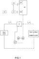
- the electronic system 4 comprises a management unit 41 for managing and processing the detected data.
- the electronic system 4 may comprise a battery 45 for powering the various components included therein.
- the electronic system 4 comprises data transmission and/or reception means 47 operatively connected with the management unit 41 and suitable to send the shot-fired information.
- the management unit 41 is also accessible from the outside, for example suitable to receive predetermined information or commands.
- the electronic system 4 comprises a memory 48 operatively connected to the management unit 41 suitable to be used by the management unit 41 to store information or access information stored therein.
- the electronic system 4 comprises a fixed sensor device 42 integral with the fixed part 2 of the firearm and a mobile sensor device 43 housed on board said mobile parts 3.
- the fixed sensor device 42 is housed on the fixed part 2 of the firearm.
- the fixed sensor device 42 and the mobile sensor device 43 are suitable to mutually influence each other according to their mutual position.
- the two devices are designed to mutually influence each other as a function of their mutual position.
- the fixed sensor device 42 and the mobile sensor device 43 are mutually magnetically sensitive with each other.
- the mobile sensor device 43 is characterized by a magnetic field and the fixed sensor device 42 is suitable to be influenced by such a magnetic field.
- the fixed sensor device 42 and the mobile sensor device 43 are positioned in respective positions such that they are facing each other.
- the mobile sensor device 43 is housed on at least one movable part 3 suitable to perform a plurality of predefined guided movements, while the fixed sensor device 42 is located in the vicinity of the mobile sensor device 43 housed on the fixed parts 2 that house said movable parts 43, for example housed in a wall 200 comprised between the fixed parts 2.
- the mobile sensor device 43 is an element of a ferromagnetic material; preferably, the mobile sensor device 43 is a permanent magnet.
- the fixed sensor device 42 comprises a magnetically sensitive element.
- the fixed sensor device 42 comprises two magnetically sensitive elements, mutually spaced apart.
- the two magnetically sensitive elements are spaced from each other, thereby defining a distance D.
- the two magnetically sensitive elements are arranged axially spaced along an axis parallel to the movement direction of the movable part 3 on which the mobile sensor device 43 is housed.
- the magnetically sensitive element is magnetically sensitive by Hall effect.
- the magnetically sensitive element comprises an electrical circuit suitable to detect the change of magnetic field induced by the movement of the mobile sensor device.
- the management unit 41 is operatively connected to the fixed sensor device 42 and is suitable to detect a movement time Tm as a function of the position of the mobile sensor device 43.
- the management unit 41 is suitable to receive and evaluate any information relating to the magnetic field variation detected by the fixed sensor device 42 as a function of the position of the mobile sensor device 43.
- the movement time Tm refers to the position of the mobile sensor device 43 during the retraction time T2.
- the movement time Tm is a fraction of the retraction time T2.
- the movement time Tm is linked to a portion of the movement, i.e. a fraction of the change in position, of the movable part 3 on which the mobile sensor device 43 is housed on board.
- such a movement time Tm corresponds with the entire retraction time T2.
- the movement time Tm is linked to the whole movement, i.e. the entire variation of position of the movable part 3 on which the mobile sensor device 43 is housed on board. In such an embodiment, therefore, the complete return movement of the movable part of interest is evaluated.
- the management unit 41 is suitable to determine the time that elapses between one magnetic field variation and the other. That is to say, from the magnetic field variation, the management unit 41 is suitable to evaluate the time of a predefined movement of a movable part 3. Preferably, the management unit 41 is suitable to detect the speed with which the magnetic field varies as a function of the position of the mobile sensor device 43 and how this influences the fixed sensor device 42.
- the management unit 41 is suitable to compare the value of the movement time Tm detected with a predetermined threshold value Ts.
- a predetermined threshold value Ts is a function of the features of firearm 1; more in particular, such a predetermined threshold value Ts is a function of the features of the at least one movable part 43 which houses the mobile sensor device 43 (and therefore the movement that this carries out).
- the predetermined threshold value Ts is stored to memory 48.
- the management unit 41 detects the shot-fired event when the value of the movement time Tm detected is lower than the threshold value Ts.
- information about the cycle time T and/or on the advancement time T1 and/or the retraction time T2 are storable, and/or information about the shot-fired event are storable.
- the management unit 41 detects the movement time Tm value, compares it with the threshold value Ts and when the movement time Tm is greater than the threshold value Ts, the racking is detected instead of the shot. Also such information is then stored to memory 48, or is sent by the data transmission and/or reception means 47.
- the mobile sensor device 43 is housed on hammer 32, or on the hammer return lever 34.
- the threshold value Ts of this embodiment is substantially about 10 milliseconds.
- the mobile sensor device 43 is housed on the connection lever 33 of hammer 32 to trigger 30.
- the threshold value Ts of this embodiment is substantially about 0.4 milliseconds.
- the management unit 41 is therefore suitable to evaluate the speed of the movements of the sensorized movable part 3, in particular a fraction of its movements performed between the firing position and the return position, so as to discriminate the movement induced by the firing, and thus characterized by high speed and therefore short timing, with respect to other movements, such as those that induce the manual movement, or manually performed by the user, which is slower.
- the movement time Tm is evaluated in relation to the speed with which the mobile sensor device 43 influences the respective fixed sensor devices 42.
- the at least one movable part on which the mobile sensor device 43 is housed is the connection lever between trigger 30 and hammer 32, which therefore performs a complex movement, and consists of several distinct movements: for example, in a first moment it is controlled in pressure by the trigger to execute the firing ( fig. 5b and 5b' ); while once the firing has been executed, the connection lever is induced in a vertical movement by the firing action ( fig. 5c and 5c' ). In particular, this movement is also due to the fact that the movement in the retraction of the breechblock in the firing event is so fast that the shooter keeps the trigger pressed, thereby leading to the necessary vertical movement of the connection lever.
- the fixed sensor device 42 is suitable to be influenced by the height variation of said connection lever. That is, the movement time is the time within which the lever moves in height from the first position to the second position.
- the fixed sensor device 42 comprises a plurality of magnetically sensitive elements comprising a first fixed sensor device 421 and a second fixed sensor device 422, preferably spaced from each other in vertical by a vertical distance Dv along a vertical axis V-V, transverse but not necessarily perpendicular to the firing axis X-X.
- the movement time Tm in this embodiment is, therefore, the time necessary for the mobile sensor device 43 for influencing the first fixed sensor device 421 and then the second fixed sensor device 422 passing alongside them.
- Said vertical distance Dv is about 3 mm.
- the firearm object of the present invention solves the typical problems of the prior art by comprising an electronic system suitable to detect exclusively the firing event.
- the firearm discriminates the reasons for which a movable part thereof has made a certain movement, identifying when this is moved due to the firing event of for other reasons.
- the electronic system is error-proof, irrefutably identifying the shot-fired event, unlike some prior art solutions.
- a further advantageous aspect lies in that the electronic system is implementable on the firearm in different embodiments and modes without affecting the operation thereof.
- the electronic system is also implementable to discriminate other events undergone by the firearm, but always a function of the relative displacement of the movable parts.
Landscapes
- Engineering & Computer Science (AREA)
- General Engineering & Computer Science (AREA)
- Aiming, Guidance, Guns With A Light Source, Armor, Camouflage, And Targets (AREA)
Description
- The present invention relates to a firearm comprising an electronic system suitable to detect the shot-fired event. Preferably, said firearm is a gun. Preferably, said firearm is an automatic firearm or semi-automatic firearm.
- In the prior art are known various solutions of firearms comprising electronic systems or on which electronic systems are mounted that are designed to detect the shot-fired event; preferably, such electronic systems are suitable to share the detected information and/or are suitable to store this information to keep track of the fired shots.
- In such a context, are known electronic systems provided with inertial devices, for example provided with accelerometers, suitable to detect the accelerations suffered by the firearm; preferably, these inertial devices, are suitable to detect the acceleration action on the firearm due to the recoil, thereby identifying the shot event.
- In these electronic systems, however, inertial systems have the drawback of not being particularly precise. For example, in fact, inertial systems are activated even when the firearm is subject to different accelerations from those resulting from a shot, like accelerations due to a fall of the firearm to the ground or a shaking thereof. In addition, inertial systems may be subject to a plurality of further drawbacks that affect the detection modes thereof, up to the non-recognition of the shot fired: for example, inertial systems are such as to detect different levels of acceleration as the firearm features vary, for example due to the addition or removal of a mass thereto; likewise, inertial systems are influenced by the manner in which the firearm is gripped or shouldered; moreover, inertial systems have the possibility that the detection systems are fixed in a more or less loose manner, thus having mechanical impedance variations between the firearm and the sensor.
- Furthermore, there are systems known from the prior art that detect the relative movements of firearm components by means of magnetic sensors. Examples of such systems can be found in
EP 1 300 648 A1DD 282 977 A5 EP 2 151 658 A1 . - The object of the present invention is to provide a firearm comprising an electronic system suitable to detect in a deterministic manner the shot-fired event; specifically, the object of the present invention is to have a firearm suitable to detect the shot-fired event in a precise and reliable manner; i.e., the firearm object of the present invention is intended to detect the shot-fired event obviating the possibility that the detection is influenced by any external agents.
- This object is achieved by a firearm according to
claim 1. Further advantages and embodiments of the firearm object of the present invention will become apparent from the dependent claims, forming the appended set of claims. - Moreover, the features and the advantages of the firearm will appear more clearly from the following description, made by way of an indicative and nonlimiting example according to the accompanying figures, in which:
-
figure 1 shows a block diagram exemplifying the operation of an electronic system included in the firearm object of the present invention according to a preferred embodiment; -
figures 2a ,2b and2c show three schematised side views of an exemplary firearm not forming part of the present invention, said firearm comprising at least one movable part comprising a shutter housing a mobile sensor device; the at least one movable part is in a starting position, in a return position and back in a starting position, respectively, wherein in this example, the starting position corresponds to the firing position; -
figures 3a, 3b and 3c show three schematised side views of a first embodiment of the firearm according to the present invention comprising at least one movable part comprising a hammer housing a mobile sensor device; the at least one movable part is in a starting position, in a firing position and in a return position, respectively, wherein in this embodiment, the starting position corresponds to the firing position; -
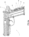
figures 4a ,4b and4c show three schematised side views of a second embodiment of the firearm according to the present invention comprising at least one movable part comprising a hammer return lever housing a mobile sensor device; the at least one movable part is in a starting position, in a firing position and in a return position, respectively, wherein in this embodiment, the starting position corresponds to the firing position; -
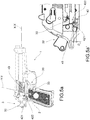
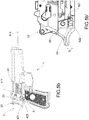
figures 5a ,5b and5c show three schematised side views of a third embodiment of the firearm according to the present invention comprising at least one movable part comprising a connection lever between trigger and hammer housing a mobile sensor device; the at least one movable part is in a starting position, in a firing position and in a return position, respectively, wherein in this embodiment, the return position differs from both the starting position and the firing position; -
figures 5a', 5b' and 5c' show three schematised enlarged side views offigures 5a ,5b and5c , respectively. - With reference to the accompanying figures,
reference numeral 1 indicates a firearm as a whole. - Preferably,
firearm 1 is a gun. - Preferably, said
firearm 1 is an automatic firearm or a semi-automatic firearm. -
Firearm 1 comprises afixed part 2, for example grippable by a user. In other words, fixedpart 2 indicates all those parts offirearm 1, such as the body, the stock, the grip, the forend, which do not perform relative movements during the firing operations. - In fact,
firearm 1 comprisesmovable parts 3 which, however, perform predefined guided movements during a firing cycle. Preferably,movable parts 3 identifies all those components that are involved in the firing cycle, i.e. all those components that perform translational, rotation, rotational-translation, tilting movements and the like such as to entail the firing or, movements induced by the shot event. - Preferably, in fact, the
movable parts 3 from a starting position move up to be disposed in a firing position, in which the ammunition is triggered in an explosion chamber; subsequently, on firing, the movable parts move up to be disposed in a return position (typically, this movement is a reaction to the firing action and, therefore, takes place at high speed): for example, during such movements, the cartridge case of the ammunition fired is extracted and expelled and a new ammunition is inserted in the explosion chamber. - In some preferred embodiments of the firearm, some movable parts conclude the firing cycle in such a manner that said return position corresponds with the starting position.
- In addition, in some embodiments, the firing position and the starting position coincide, while the return position is an intermediate position between them.
- In other preferred embodiments of the firearm, on the other hand, some movable parts conclude the firing cycle in a different position than the starting position, in other words the return position does not correspond with the starting position.
- That is to say that depending on the type of firearm, and depending on the type of movable part taken into consideration, the return position in which this is located as a result of firing does not necessarily correspond to the starting position in which it was at the beginning of the firing cycle.
- According to a first embodiment of the invention, the
movable parts 3 comprise ahammer 32. - According to a second embodiment of the invention, the
movable parts 3 comprise aconnection lever 33 ofhammer 32 to trigger 30, the latter in turn comprised between themovable parts 3. - According to a third embodiment of the invention, the
movable parts 3 comprise areturn lever 34 ofhammer 32, in turn comprised between themovable parts 3. - According to the invention, the entire firing cycle has a cycle time T.
- During an entire firing cycle, the
movable parts 3 start from a starting position to go into a firing position in which the ammunition is triggered and are moved out of the explosion of reaction in the combustion chamber, in the return position. However, in some embodiments, themovable parts 3 at the beginning of cycle are already in a firing position, they are moved out of the explosion reaction in the explosion chamber, in the return position, and again subsequently they perform an advancement to return to the starting position of the cycle. - In each cycle time T, therefore, a retraction time T2 is identified, which is the timing in which the
movable part 3 is induced by the firing action to be disposed in a return position starting from the firing position. - In addition, in the cycle time T, an advancement time T1 is also identified, i.e. the timing in which the
movable part 3 from the starting position is disposed in the firing position, or the timing in which themovable part 3 from the return position is disposed in the firing position (where such a distinction is due to the type of firearm and movable part under examination). - In other words, the cycle time T is identifiable as the sum of the retraction time T2 and the advancement time T1.
-
Firearm 1 object of the present invention comprises anelectronic system 4 suitable to detect the shot-fired event. Preferably, theelectronic system 4 is suitable to discriminate the shot-fired event from other events that have occurred tofirearm 1, such as a bump. In addition, theelectronic system 4 is suitable to detect the shot-fired event distinguishing it from a "fake" shot. In addition, theelectronic system 4 is suitable to detect the shot-fired event distinguishing it from a manual movement of the movable parts (for example due to the fact that the firearm has "cycled", i.e. has been manually moved along a firing cycle, in other words due to the fact that the firearm has performed a "racking"). Preferably, theelectronic system 4, as widely described hereinafter, is immune from the possibility that it may be conditioned in its detection by any actions external to the firearm, such as a shaking or a fall thereof. - According to the invention, the
electronic system 4 comprises amanagement unit 41 for managing and processing the detected data. - In addition, the
electronic system 4 may comprise abattery 45 for powering the various components included therein. - In addition, in a preferred embodiment, the
electronic system 4 comprises data transmission and/or reception means 47 operatively connected with themanagement unit 41 and suitable to send the shot-fired information. Preferably, by such data transmission and/or reception means 47, themanagement unit 41 is also accessible from the outside, for example suitable to receive predetermined information or commands. - In a preferred embodiment, moreover, the
electronic system 4 comprises amemory 48 operatively connected to themanagement unit 41 suitable to be used by themanagement unit 41 to store information or access information stored therein. - According to the invention, the
electronic system 4 comprises afixed sensor device 42 integral with thefixed part 2 of the firearm and amobile sensor device 43 housed on board saidmobile parts 3. Preferably, thefixed sensor device 42 is housed on thefixed part 2 of the firearm. - According to the invention, the
fixed sensor device 42 and themobile sensor device 43 are suitable to mutually influence each other according to their mutual position. In other words, between thefixed sensor device 42 and themobile sensor device 43 there is no physical contact, however the two devices are designed to mutually influence each other as a function of their mutual position. According to the invention, thefixed sensor device 42 and themobile sensor device 43 are mutually magnetically sensitive with each other. - Preferably, for example, the
mobile sensor device 43 is characterized by a magnetic field and thefixed sensor device 42 is suitable to be influenced by such a magnetic field. - In a preferred embodiment, the
fixed sensor device 42 and themobile sensor device 43 are positioned in respective positions such that they are facing each other. In other words, themobile sensor device 43 is housed on at least onemovable part 3 suitable to perform a plurality of predefined guided movements, while thefixed sensor device 42 is located in the vicinity of themobile sensor device 43 housed on thefixed parts 2 that house saidmovable parts 43, for example housed in a wall 200 comprised between thefixed parts 2. - According to the invention, the
mobile sensor device 43 is an element of a ferromagnetic material; preferably, themobile sensor device 43 is a permanent magnet. - According to the invention, the
fixed sensor device 42 comprises a magnetically sensitive element. - Preferably, the
fixed sensor device 42 comprises two magnetically sensitive elements, mutually spaced apart. For example, the two magnetically sensitive elements are spaced from each other, thereby defining a distance D. Preferably, the two magnetically sensitive elements are arranged axially spaced along an axis parallel to the movement direction of themovable part 3 on which themobile sensor device 43 is housed. - According to a preferred embodiment, the magnetically sensitive element is magnetically sensitive by Hall effect. Preferably, the magnetically sensitive element comprises an electrical circuit suitable to detect the change of magnetic field induced by the movement of the mobile sensor device.
- According to the invention, the
management unit 41 is operatively connected to the fixedsensor device 42 and is suitable to detect a movement time Tm as a function of the position of themobile sensor device 43. In other words, themanagement unit 41 is suitable to receive and evaluate any information relating to the magnetic field variation detected by the fixedsensor device 42 as a function of the position of themobile sensor device 43. - According to the invention, the movement time Tm refers to the position of the
mobile sensor device 43 during the retraction time T2. - In other words, the movement time Tm is a fraction of the retraction time T2. In these embodiments, the movement time Tm is linked to a portion of the movement, i.e. a fraction of the change in position, of the
movable part 3 on which themobile sensor device 43 is housed on board. - In some preferred embodiments, such a movement time Tm corresponds with the entire retraction time T2. In such embodiments, the movement time Tm is linked to the whole movement, i.e. the entire variation of position of the
movable part 3 on which themobile sensor device 43 is housed on board. In such an embodiment, therefore, the complete return movement of the movable part of interest is evaluated. - In a preferred embodiment, the
management unit 41 is suitable to determine the time that elapses between one magnetic field variation and the other. That is to say, from the magnetic field variation, themanagement unit 41 is suitable to evaluate the time of a predefined movement of amovable part 3. Preferably, themanagement unit 41 is suitable to detect the speed with which the magnetic field varies as a function of the position of themobile sensor device 43 and how this influences the fixedsensor device 42. - According to the invention, the
management unit 41 is suitable to compare the value of the movement time Tm detected with a predetermined threshold value Ts. For example, such a predetermined threshold value Ts is a function of the features offirearm 1; more in particular, such a predetermined threshold value Ts is a function of the features of the at least onemovable part 43 which houses the mobile sensor device 43 (and therefore the movement that this carries out). Preferably, the predetermined threshold value Ts is stored tomemory 48. - According to the invention, the
management unit 41 detects the shot-fired event when the value of the movement time Tm detected is lower than the threshold value Ts. - In a preferred embodiment, in addition to the threshold value Ts, information about the cycle time T and/or on the advancement time T1 and/or the retraction time T2 are storable, and/or information about the shot-fired event are storable.
- In further embodiment variants, other events are also recognisable by means of the
electronic system 4. - For example, by means of the electronic system it is also recognizable when the firearm is manually "cycled". In fact, whenever a movement time Tm higher than the threshold value Ts is detected, it means that the movable part in question has been moved manually, i.e. cycled irrespective of the shot-fired event.
- In other words, the
management unit 41 detects the movement time Tm value, compares it with the threshold value Ts and when the movement time Tm is greater than the threshold value Ts, the racking is detected instead of the shot. Also such information is then stored tomemory 48, or is sent by the data transmission and/or reception means 47. - According to one embodiment of the invention, the
mobile sensor device 43 is housed onhammer 32, or on thehammer return lever 34. Preferably, the threshold value Ts of this embodiment is substantially about 10 milliseconds. - According to another embodiment of the invention, the
mobile sensor device 43 is housed on theconnection lever 33 ofhammer 32 to trigger 30. Preferably, the threshold value Ts of this embodiment is substantially about 0.4 milliseconds. - In other words, in each of the above embodiments, the
management unit 41 is therefore suitable to evaluate the speed of the movements of the sensorizedmovable part 3, in particular a fraction of its movements performed between the firing position and the return position, so as to discriminate the movement induced by the firing, and thus characterized by high speed and therefore short timing, with respect to other movements, such as those that induce the manual movement, or manually performed by the user, which is slower. - In some preferred embodiments, which provide a plurality of magnetically sensitive elements in the fixed
sensor device 42, preferably a firstfixed sensor device 421 and a secondfixed sensor device 422, the movement time Tm is evaluated in relation to the speed with which themobile sensor device 43 influences the respective fixedsensor devices 42. - In some embodiments of the invention, such as that shown in
figure 5 , the at least one movable part on which themobile sensor device 43 is housed is the connection lever betweentrigger 30 andhammer 32, which therefore performs a complex movement, and consists of several distinct movements: for example, in a first moment it is controlled in pressure by the trigger to execute the firing (fig. 5b and 5b' ); while once the firing has been executed, the connection lever is induced in a vertical movement by the firing action (fig. 5c and 5c' ). In particular, this movement is also due to the fact that the movement in the retraction of the breechblock in the firing event is so fast that the shooter keeps the trigger pressed, thereby leading to the necessary vertical movement of the connection lever. - In other words, the fixed
sensor device 42 is suitable to be influenced by the height variation of said connection lever. That is, the movement time is the time within which the lever moves in height from the first position to the second position. - Preferably, also in this embodiment, the fixed
sensor device 42 comprises a plurality of magnetically sensitive elements comprising a firstfixed sensor device 421 and a secondfixed sensor device 422, preferably spaced from each other in vertical by a vertical distance Dv along a vertical axis V-V, transverse but not necessarily perpendicular to the firing axis X-X. The movement time Tm in this embodiment is, therefore, the time necessary for themobile sensor device 43 for influencing the firstfixed sensor device 421 and then the secondfixed sensor device 422 passing alongside them. Said vertical distance Dv is about 3 mm. - Innovatively, the firearm object of the present invention solves the typical problems of the prior art by comprising an electronic system suitable to detect exclusively the firing event.
- Advantageously, the firearm discriminates the reasons for which a movable part thereof has made a certain movement, identifying when this is moved due to the firing event of for other reasons.
- Moreover, advantageously no external agent affects the manner in which the electronic system operates. Advantageously, therefore, the electronic system is error-proof, irrefutably identifying the shot-fired event, unlike some prior art solutions.
- A further advantageous aspect lies in that the electronic system is implementable on the firearm in different embodiments and modes without affecting the operation thereof.
- Advantageously, the electronic system is also implementable to discriminate other events undergone by the firearm, but always a function of the relative displacement of the movable parts.
- It is clear that a man skilled in the art may make changes to the firearm described above in order to meet incidental needs, all falling within the scope of protection defined in the following claims.
Claims (12)
- Firearm (1) comprising:- a fixed part (2) for example grippable by a user;- at least one movable part (3) that performs a predefined guided movement during the firing cycle having a cycle time (T), wherein the firing cycle comprises a retraction time (T2) in which the movable part (3) is induced by the firing action to be disposed in a return position starting from a firing position, and an advancement time (T1) in which the movable part (3) starting from a starting position is disposed in a firing position or wherein the movable part (3) starting from a return position is disposed in a firing position;- an electronic system (4) suitable to detect the shot fired event, comprising:wherein the fixed sensor device (42) and the mobile sensor device (43) are mutually magnetically sensitive so as to influence each other according to their mutual position, the mobile sensor device being an element made of a ferromagnetic material, preferably a permanent magnet, and the fixed sensor device (42) comprising a magnetically sensitive element (421);i) a management unit (41);ii) a fixed sensor device (42) integral with the fixed part (2) of the firearm, preferably housed on the fixed part (2);iii) a mobile sensor device (43) housed on board said movable part (3);
wherein said movable part (3) comprises a hammer (32) and said mobile sensor device (43) is housed on the hammer (32), or said movable part (3) comprises a hammer (32) and a return lever (34) connected to the hammer (32) and said mobile sensor device (43) is housed on the return lever (34), or said movable part (3) comprises a connection lever (33) connecting the hammer (32) to the trigger (30) and said mobile sensor device (43) is housed on the connection lever (33);
wherein the management unit (41) is operatively connected to the fixed sensor device (42) and is suitable to detect a movement time (Tm) as a function of the position of the mobile sensor device (43) during the retraction time (T2) ;
wherein the management unit (41) is suitable to detect the shot-fired event upon the correspondence of movement time value (Tm) lower than a predefined threshold value (Ts), wherein the maximum value of the movement time value (Tm) is equal to the retraction time (T2). - Firearm (1) according to claim 1, wherein the return position corresponds with the starting position.
- Firearm (1) according to any of the preceding claims, wherein the fixed sensor device (42) is positioned in the fixed part (2) preferably on a wall (200) that delimits said fixed part and is facing the at least one movable part (3) that carries the mobile sensor device (43) on board.
- Firearm (1) according to anyone of the previous claims, wherein the fixed sensor device (42) comprises two magnetically sensitive elements (421), mutually spaced apart.
- Firearm (1) according to anyone of the previous claims, wherein the magnetically sensitive element (421) comprises an electrical circuit suitable to detect the change of magnetic field induced by the movement of the mobile sensor device (43).
- Firearm (1) according to any of the preceding claims, wherein the electronic system (4) comprises data transmission and/or reception means (47) operatively connected with the management unit (41) suitable to send the shot-fired information.
- Firearm (1) according to any of the preceding claims, wherein the electronic system (4) comprises a memory (48) operatively connected to the management unit (41), wherein the memory (48) is able to store the information of the threshold value (Ts) and/or of the cycle time information (T) and/or of the advancement time (T1) and/or of the retraction time (T2) and/or of the shot-fired event and/or the weapon cycled event.
- Firearm (1) according to any of the preceding claims, wherein the electronic system (4) comprises a battery (45) for the power supply of the management unit (41) and/or of fixed sensor device (42) and/or of data transmission and/or of reception means (47) and/or of the memory (48).
- Firearm (1) according to anyone of the previous claims, wherein the mobile sensor device (43) is housed on the hammer (32) or on the return lever (34), the threshold value (Ts) is substantially about 10 milliseconds.
- Firearm (1) according to anyone of the previous claims, wherein the mobile sensor device (43) is housed on said connection lever (33) the threshold value (Ts) is substantially about 0.4 milliseconds.
- Firearm (1) according to any of the preceding claims, wherein said firearm (1) is an automatic or semi-automatic weapon.
- Firearm (1) according to any of the previous claims, wherein said firearm (1) is a gun.
Applications Claiming Priority (2)
| Application Number | Priority Date | Filing Date | Title |
|---|---|---|---|
| IT102016000081312A IT201600081312A1 (en) | 2016-08-02 | 2016-08-02 | FIREARMS INCLUDING AN ELECTRONIC SYSTEM |
| PCT/IB2017/054576 WO2018025132A1 (en) | 2016-08-02 | 2017-07-27 | Firearm comprising an electronic system |
Publications (2)
| Publication Number | Publication Date |
|---|---|
| EP3494354A1 EP3494354A1 (en) | 2019-06-12 |
| EP3494354B1 true EP3494354B1 (en) | 2020-08-05 |
Family
ID=58670115
Family Applications (1)
| Application Number | Title | Priority Date | Filing Date |
|---|---|---|---|
| EP17764442.4A Active EP3494354B1 (en) | 2016-08-02 | 2017-07-27 | Firearm comprising an electronic system |
Country Status (3)
| Country | Link |
|---|---|
| EP (1) | EP3494354B1 (en) |
| IT (1) | IT201600081312A1 (en) |
| WO (1) | WO2018025132A1 (en) |
Family Cites Families (5)
| Publication number | Priority date | Publication date | Assignee | Title |
|---|---|---|---|---|
| DD282977A5 (en) * | 1989-05-02 | 1990-09-26 | Thaelmann Fahrzeug Jagdwaffen | DEVICE FOR FEEDBACK CAPTURE, ESPECIALLY FOR SPORTS WEAR |
| DE4203585C2 (en) * | 1992-02-07 | 1996-04-25 | Heckler & Koch Gmbh | Device for determining the state of wear of a firearm |
| DE10148677A1 (en) * | 2001-10-02 | 2003-04-24 | Gaston Glock | Gun with a device for determining the number of shots |
| ES2472704T3 (en) * | 2007-05-30 | 2014-07-02 | Ra�L Delgado Acarreta | Device to control ammo consumption in real time |
| DE102011100101A1 (en) * | 2011-04-29 | 2012-10-31 | Rheinmetall Waffe Munition Gmbh | shot counter |
-
2016
- 2016-08-02 IT IT102016000081312A patent/IT201600081312A1/en unknown
-
2017
- 2017-07-27 WO PCT/IB2017/054576 patent/WO2018025132A1/en not_active Ceased
- 2017-07-27 EP EP17764442.4A patent/EP3494354B1/en active Active
Non-Patent Citations (1)
| Title |
|---|
| None * |
Also Published As
| Publication number | Publication date |
|---|---|
| IT201600081312A1 (en) | 2018-02-02 |
| WO2018025132A1 (en) | 2018-02-08 |
| EP3494354A1 (en) | 2019-06-12 |
Similar Documents
| Publication | Publication Date | Title |
|---|---|---|
| US8387295B2 (en) | Handgun | |
| US10866048B2 (en) | Device for counting live shots, blank shots and dry shots | |
| US8109023B2 (en) | Shot counter | |
| EP3295110B1 (en) | Firearm comprising a magazine detection group | |
| US10900732B2 (en) | Electromagnetic firing system for firearm with firing event tracking | |
| US10001335B2 (en) | Trigger assembly of a precision guided firearm | |
| US11473866B1 (en) | Electromechanical sear and methods of operating a gun using the same | |
| US9303937B2 (en) | Counting device | |
| US6643968B2 (en) | Pistol with a device for determining the number of shots | |
| US12385708B2 (en) | Safety for firearm electromagnetic firing system | |
| US7661217B2 (en) | Shot counter | |
| SG139629A1 (en) | Device for detecting and counting shots fired by an automatic or semi- automatic fire arm, and fire arm equipped with such a device | |
| WO2022226454A1 (en) | Electromechanical trigger and methods of operating a gun using the same | |
| EP3295112B1 (en) | Gun comprising an electronic device | |
| WO2018025132A1 (en) | Firearm comprising an electronic system | |
| WO2022238997A1 (en) | A firearm trigger control device | |
| KR101976581B1 (en) | Trigger mechanism using double magnet of the firearms link and method of operating the same | |
| EP4392730B1 (en) | Device, system and method of detecting and counting shots | |
| US12372319B1 (en) | Fire control mechanism | |
| WO2023091110A1 (en) | Hammer tracking mechanism in firearms | |
| EP4500102A1 (en) | Safety for firearm electromagnetic firing system | |
| TR202016579A2 (en) | A shot-sensing damping mechanism |
Legal Events
| Date | Code | Title | Description |
|---|---|---|---|
| STAA | Information on the status of an ep patent application or granted ep patent |
Free format text: STATUS: UNKNOWN |
|
| STAA | Information on the status of an ep patent application or granted ep patent |
Free format text: STATUS: THE INTERNATIONAL PUBLICATION HAS BEEN MADE |
|
| TPAC | Observations filed by third parties |
Free format text: ORIGINAL CODE: EPIDOSNTIPA |
|
| PUAI | Public reference made under article 153(3) epc to a published international application that has entered the european phase |
Free format text: ORIGINAL CODE: 0009012 |
|
| STAA | Information on the status of an ep patent application or granted ep patent |
Free format text: STATUS: REQUEST FOR EXAMINATION WAS MADE |
|
| 17P | Request for examination filed |
Effective date: 20190130 |
|
| AK | Designated contracting states |
Kind code of ref document: A1 Designated state(s): AL AT BE BG CH CY CZ DE DK EE ES FI FR GB GR HR HU IE IS IT LI LT LU LV MC MK MT NL NO PL PT RO RS SE SI SK SM TR |
|
| AX | Request for extension of the european patent |
Extension state: BA ME |
|
| DAV | Request for validation of the european patent (deleted) | ||
| DAX | Request for extension of the european patent (deleted) | ||
| GRAP | Despatch of communication of intention to grant a patent |
Free format text: ORIGINAL CODE: EPIDOSNIGR1 |
|
| STAA | Information on the status of an ep patent application or granted ep patent |
Free format text: STATUS: GRANT OF PATENT IS INTENDED |
|
| INTG | Intention to grant announced |
Effective date: 20200319 |
|
| GRAS | Grant fee paid |
Free format text: ORIGINAL CODE: EPIDOSNIGR3 |
|
| GRAA | (expected) grant |
Free format text: ORIGINAL CODE: 0009210 |
|
| STAA | Information on the status of an ep patent application or granted ep patent |
Free format text: STATUS: THE PATENT HAS BEEN GRANTED |
|
| AK | Designated contracting states |
Kind code of ref document: B1 Designated state(s): AL AT BE BG CH CY CZ DE DK EE ES FI FR GB GR HR HU IE IS IT LI LT LU LV MC MK MT NL NO PL PT RO RS SE SI SK SM TR |
|
| REG | Reference to a national code |
Ref country code: GB Ref legal event code: FG4D |
|
| REG | Reference to a national code |
Ref country code: CH Ref legal event code: EP |
|
| REG | Reference to a national code |
Ref country code: AT Ref legal event code: REF Ref document number: 1299315 Country of ref document: AT Kind code of ref document: T Effective date: 20200815 |
|
| REG | Reference to a national code |
Ref country code: IE Ref legal event code: FG4D |
|
| REG | Reference to a national code |
Ref country code: DE Ref legal event code: R096 Ref document number: 602017021192 Country of ref document: DE |
|
| REG | Reference to a national code |
Ref country code: LT Ref legal event code: MG4D |
|
| REG | Reference to a national code |
Ref country code: NL Ref legal event code: MP Effective date: 20200805 |
|
| REG | Reference to a national code |
Ref country code: AT Ref legal event code: MK05 Ref document number: 1299315 Country of ref document: AT Kind code of ref document: T Effective date: 20200805 |
|
| PG25 | Lapsed in a contracting state [announced via postgrant information from national office to epo] |
Ref country code: PT Free format text: LAPSE BECAUSE OF FAILURE TO SUBMIT A TRANSLATION OF THE DESCRIPTION OR TO PAY THE FEE WITHIN THE PRESCRIBED TIME-LIMIT Effective date: 20201207 Ref country code: GR Free format text: LAPSE BECAUSE OF FAILURE TO SUBMIT A TRANSLATION OF THE DESCRIPTION OR TO PAY THE FEE WITHIN THE PRESCRIBED TIME-LIMIT Effective date: 20201106 Ref country code: NO Free format text: LAPSE BECAUSE OF FAILURE TO SUBMIT A TRANSLATION OF THE DESCRIPTION OR TO PAY THE FEE WITHIN THE PRESCRIBED TIME-LIMIT Effective date: 20201105 Ref country code: SE Free format text: LAPSE BECAUSE OF FAILURE TO SUBMIT A TRANSLATION OF THE DESCRIPTION OR TO PAY THE FEE WITHIN THE PRESCRIBED TIME-LIMIT Effective date: 20200805 Ref country code: FI Free format text: LAPSE BECAUSE OF FAILURE TO SUBMIT A TRANSLATION OF THE DESCRIPTION OR TO PAY THE FEE WITHIN THE PRESCRIBED TIME-LIMIT Effective date: 20200805 Ref country code: HR Free format text: LAPSE BECAUSE OF FAILURE TO SUBMIT A TRANSLATION OF THE DESCRIPTION OR TO PAY THE FEE WITHIN THE PRESCRIBED TIME-LIMIT Effective date: 20200805 Ref country code: AT Free format text: LAPSE BECAUSE OF FAILURE TO SUBMIT A TRANSLATION OF THE DESCRIPTION OR TO PAY THE FEE WITHIN THE PRESCRIBED TIME-LIMIT Effective date: 20200805 Ref country code: BG Free format text: LAPSE BECAUSE OF FAILURE TO SUBMIT A TRANSLATION OF THE DESCRIPTION OR TO PAY THE FEE WITHIN THE PRESCRIBED TIME-LIMIT Effective date: 20201105 Ref country code: ES Free format text: LAPSE BECAUSE OF FAILURE TO SUBMIT A TRANSLATION OF THE DESCRIPTION OR TO PAY THE FEE WITHIN THE PRESCRIBED TIME-LIMIT Effective date: 20200805 Ref country code: LT Free format text: LAPSE BECAUSE OF FAILURE TO SUBMIT A TRANSLATION OF THE DESCRIPTION OR TO PAY THE FEE WITHIN THE PRESCRIBED TIME-LIMIT Effective date: 20200805 |
|
| PG25 | Lapsed in a contracting state [announced via postgrant information from national office to epo] |
Ref country code: PL Free format text: LAPSE BECAUSE OF FAILURE TO SUBMIT A TRANSLATION OF THE DESCRIPTION OR TO PAY THE FEE WITHIN THE PRESCRIBED TIME-LIMIT Effective date: 20200805 Ref country code: RS Free format text: LAPSE BECAUSE OF FAILURE TO SUBMIT A TRANSLATION OF THE DESCRIPTION OR TO PAY THE FEE WITHIN THE PRESCRIBED TIME-LIMIT Effective date: 20200805 Ref country code: LV Free format text: LAPSE BECAUSE OF FAILURE TO SUBMIT A TRANSLATION OF THE DESCRIPTION OR TO PAY THE FEE WITHIN THE PRESCRIBED TIME-LIMIT Effective date: 20200805 Ref country code: NL Free format text: LAPSE BECAUSE OF FAILURE TO SUBMIT A TRANSLATION OF THE DESCRIPTION OR TO PAY THE FEE WITHIN THE PRESCRIBED TIME-LIMIT Effective date: 20200805 Ref country code: IS Free format text: LAPSE BECAUSE OF FAILURE TO SUBMIT A TRANSLATION OF THE DESCRIPTION OR TO PAY THE FEE WITHIN THE PRESCRIBED TIME-LIMIT Effective date: 20201205 |
|
| PG25 | Lapsed in a contracting state [announced via postgrant information from national office to epo] |
Ref country code: DK Free format text: LAPSE BECAUSE OF FAILURE TO SUBMIT A TRANSLATION OF THE DESCRIPTION OR TO PAY THE FEE WITHIN THE PRESCRIBED TIME-LIMIT Effective date: 20200805 Ref country code: CZ Free format text: LAPSE BECAUSE OF FAILURE TO SUBMIT A TRANSLATION OF THE DESCRIPTION OR TO PAY THE FEE WITHIN THE PRESCRIBED TIME-LIMIT Effective date: 20200805 Ref country code: RO Free format text: LAPSE BECAUSE OF FAILURE TO SUBMIT A TRANSLATION OF THE DESCRIPTION OR TO PAY THE FEE WITHIN THE PRESCRIBED TIME-LIMIT Effective date: 20200805 Ref country code: SM Free format text: LAPSE BECAUSE OF FAILURE TO SUBMIT A TRANSLATION OF THE DESCRIPTION OR TO PAY THE FEE WITHIN THE PRESCRIBED TIME-LIMIT Effective date: 20200805 Ref country code: EE Free format text: LAPSE BECAUSE OF FAILURE TO SUBMIT A TRANSLATION OF THE DESCRIPTION OR TO PAY THE FEE WITHIN THE PRESCRIBED TIME-LIMIT Effective date: 20200805 |
|
| REG | Reference to a national code |
Ref country code: DE Ref legal event code: R097 Ref document number: 602017021192 Country of ref document: DE |
|
| PG25 | Lapsed in a contracting state [announced via postgrant information from national office to epo] |
Ref country code: AL Free format text: LAPSE BECAUSE OF FAILURE TO SUBMIT A TRANSLATION OF THE DESCRIPTION OR TO PAY THE FEE WITHIN THE PRESCRIBED TIME-LIMIT Effective date: 20200805 |
|
| PLBE | No opposition filed within time limit |
Free format text: ORIGINAL CODE: 0009261 |
|
| STAA | Information on the status of an ep patent application or granted ep patent |
Free format text: STATUS: NO OPPOSITION FILED WITHIN TIME LIMIT |
|
| PG25 | Lapsed in a contracting state [announced via postgrant information from national office to epo] |
Ref country code: SK Free format text: LAPSE BECAUSE OF FAILURE TO SUBMIT A TRANSLATION OF THE DESCRIPTION OR TO PAY THE FEE WITHIN THE PRESCRIBED TIME-LIMIT Effective date: 20200805 |
|
| 26N | No opposition filed |
Effective date: 20210507 |
|
| PG25 | Lapsed in a contracting state [announced via postgrant information from national office to epo] |
Ref country code: SI Free format text: LAPSE BECAUSE OF FAILURE TO SUBMIT A TRANSLATION OF THE DESCRIPTION OR TO PAY THE FEE WITHIN THE PRESCRIBED TIME-LIMIT Effective date: 20200805 |
|
| REG | Reference to a national code |
Ref country code: CH Ref legal event code: PL |
|
| GBPC | Gb: european patent ceased through non-payment of renewal fee |
Effective date: 20210727 |
|
| PG25 | Lapsed in a contracting state [announced via postgrant information from national office to epo] |
Ref country code: MC Free format text: LAPSE BECAUSE OF FAILURE TO SUBMIT A TRANSLATION OF THE DESCRIPTION OR TO PAY THE FEE WITHIN THE PRESCRIBED TIME-LIMIT Effective date: 20200805 |
|
| PG25 | Lapsed in a contracting state [announced via postgrant information from national office to epo] |
Ref country code: LI Free format text: LAPSE BECAUSE OF NON-PAYMENT OF DUE FEES Effective date: 20210731 Ref country code: GB Free format text: LAPSE BECAUSE OF NON-PAYMENT OF DUE FEES Effective date: 20210727 Ref country code: CH Free format text: LAPSE BECAUSE OF NON-PAYMENT OF DUE FEES Effective date: 20210731 |
|
| PG25 | Lapsed in a contracting state [announced via postgrant information from national office to epo] |
Ref country code: LU Free format text: LAPSE BECAUSE OF NON-PAYMENT OF DUE FEES Effective date: 20210727 Ref country code: FR Free format text: LAPSE BECAUSE OF NON-PAYMENT OF DUE FEES Effective date: 20210731 |
|
| PG25 | Lapsed in a contracting state [announced via postgrant information from national office to epo] |
Ref country code: IE Free format text: LAPSE BECAUSE OF NON-PAYMENT OF DUE FEES Effective date: 20210727 |
|
| P01 | Opt-out of the competence of the unified patent court (upc) registered |
Effective date: 20230522 |
|
| PG25 | Lapsed in a contracting state [announced via postgrant information from national office to epo] |
Ref country code: CY Free format text: LAPSE BECAUSE OF FAILURE TO SUBMIT A TRANSLATION OF THE DESCRIPTION OR TO PAY THE FEE WITHIN THE PRESCRIBED TIME-LIMIT Effective date: 20200805 |
|
| PG25 | Lapsed in a contracting state [announced via postgrant information from national office to epo] |
Ref country code: HU Free format text: LAPSE BECAUSE OF FAILURE TO SUBMIT A TRANSLATION OF THE DESCRIPTION OR TO PAY THE FEE WITHIN THE PRESCRIBED TIME-LIMIT; INVALID AB INITIO Effective date: 20170727 |
|
| PG25 | Lapsed in a contracting state [announced via postgrant information from national office to epo] |
Ref country code: MK Free format text: LAPSE BECAUSE OF FAILURE TO SUBMIT A TRANSLATION OF THE DESCRIPTION OR TO PAY THE FEE WITHIN THE PRESCRIBED TIME-LIMIT Effective date: 20200805 |
|
| PG25 | Lapsed in a contracting state [announced via postgrant information from national office to epo] |
Ref country code: MT Free format text: LAPSE BECAUSE OF FAILURE TO SUBMIT A TRANSLATION OF THE DESCRIPTION OR TO PAY THE FEE WITHIN THE PRESCRIBED TIME-LIMIT Effective date: 20200805 |
|
| PGFP | Annual fee paid to national office [announced via postgrant information from national office to epo] |
Ref country code: DE Payment date: 20250725 Year of fee payment: 9 |
|
| PGFP | Annual fee paid to national office [announced via postgrant information from national office to epo] |
Ref country code: IT Payment date: 20250624 Year of fee payment: 9 |
|
| PGFP | Annual fee paid to national office [announced via postgrant information from national office to epo] |
Ref country code: BE Payment date: 20250721 Year of fee payment: 9 |
|
| PG25 | Lapsed in a contracting state [announced via postgrant information from national office to epo] |
Ref country code: TR Free format text: LAPSE BECAUSE OF FAILURE TO SUBMIT A TRANSLATION OF THE DESCRIPTION OR TO PAY THE FEE WITHIN THE PRESCRIBED TIME-LIMIT Effective date: 20200805 |