EP3494057B1 - Containers with adhesively attached chimes - Google Patents
Containers with adhesively attached chimes Download PDFInfo
- Publication number
- EP3494057B1 EP3494057B1 EP17764432.5A EP17764432A EP3494057B1 EP 3494057 B1 EP3494057 B1 EP 3494057B1 EP 17764432 A EP17764432 A EP 17764432A EP 3494057 B1 EP3494057 B1 EP 3494057B1
- Authority
- EP
- European Patent Office
- Prior art keywords
- container
- inner hub
- central projection
- central
- chime
- Prior art date
- Legal status (The legal status is an assumption and is not a legal conclusion. Google has not performed a legal analysis and makes no representation as to the accuracy of the status listed.)
- Active
Links
Images


Classifications
-
- B—PERFORMING OPERATIONS; TRANSPORTING
- B65—CONVEYING; PACKING; STORING; HANDLING THIN OR FILAMENTARY MATERIAL
- B65D—CONTAINERS FOR STORAGE OR TRANSPORT OF ARTICLES OR MATERIALS, e.g. BAGS, BARRELS, BOTTLES, BOXES, CANS, CARTONS, CRATES, DRUMS, JARS, TANKS, HOPPERS, FORWARDING CONTAINERS; ACCESSORIES, CLOSURES, OR FITTINGS THEREFOR; PACKAGING ELEMENTS; PACKAGES
- B65D23/00—Details of bottles or jars not otherwise provided for
- B65D23/001—Supporting means fixed to the container
-
- B—PERFORMING OPERATIONS; TRANSPORTING
- B65—CONVEYING; PACKING; STORING; HANDLING THIN OR FILAMENTARY MATERIAL
- B65D—CONTAINERS FOR STORAGE OR TRANSPORT OF ARTICLES OR MATERIALS, e.g. BAGS, BARRELS, BOTTLES, BOXES, CANS, CARTONS, CRATES, DRUMS, JARS, TANKS, HOPPERS, FORWARDING CONTAINERS; ACCESSORIES, CLOSURES, OR FITTINGS THEREFOR; PACKAGING ELEMENTS; PACKAGES
- B65D25/00—Details of other kinds or types of rigid or semi-rigid containers
- B65D25/20—External fittings
- B65D25/24—External fittings for spacing bases of containers from supporting surfaces, e.g. legs
-
- B—PERFORMING OPERATIONS; TRANSPORTING
- B65—CONVEYING; PACKING; STORING; HANDLING THIN OR FILAMENTARY MATERIAL
- B65D—CONTAINERS FOR STORAGE OR TRANSPORT OF ARTICLES OR MATERIALS, e.g. BAGS, BARRELS, BOTTLES, BOXES, CANS, CARTONS, CRATES, DRUMS, JARS, TANKS, HOPPERS, FORWARDING CONTAINERS; ACCESSORIES, CLOSURES, OR FITTINGS THEREFOR; PACKAGING ELEMENTS; PACKAGES
- B65D11/00—Containers having bodies formed by interconnecting or uniting two or more rigid, or substantially rigid, components made wholly or mainly of plastics material
- B65D11/02—Containers having bodies formed by interconnecting or uniting two or more rigid, or substantially rigid, components made wholly or mainly of plastics material of curved cross-section
- B65D11/06—Drums or barrels
- B65D11/08—Arrangements of filling or discharging apertures
-
- B—PERFORMING OPERATIONS; TRANSPORTING
- B67—OPENING, CLOSING OR CLEANING BOTTLES, JARS OR SIMILAR CONTAINERS; LIQUID HANDLING
- B67D—DISPENSING, DELIVERING OR TRANSFERRING LIQUIDS, NOT OTHERWISE PROVIDED FOR
- B67D1/00—Apparatus or devices for dispensing beverages on draught
- B67D1/08—Details
- B67D1/0889—Supports
- B67D1/0891—Supports for the beverage container
-
- B—PERFORMING OPERATIONS; TRANSPORTING
- B65—CONVEYING; PACKING; STORING; HANDLING THIN OR FILAMENTARY MATERIAL
- B65D—CONTAINERS FOR STORAGE OR TRANSPORT OF ARTICLES OR MATERIALS, e.g. BAGS, BARRELS, BOTTLES, BOXES, CANS, CARTONS, CRATES, DRUMS, JARS, TANKS, HOPPERS, FORWARDING CONTAINERS; ACCESSORIES, CLOSURES, OR FITTINGS THEREFOR; PACKAGING ELEMENTS; PACKAGES
- B65D2231/00—Means for facilitating the complete expelling of the contents
- B65D2231/005—Means for facilitating the complete expelling of the contents the container being rigid
- B65D2231/007—Funnels or the like
- B65D2231/008—Funnels or the like integral with the container wall
Definitions
- This invention relates to containers, particularly kegs, which are suitable for holding beverages such as beer or fruit juices as well as other liquids.
- Kegs for holding beverages such as beer are increasingly being manufactured of plastics. They are cheaper to manufacture and transport compared with traditional metal kegs, and they can be recycled without having to be returned over long distances for re-filling.
- Such kegs include a main container which is formed by blow moulding, and at least one injection moulded chime secured to the top end, or both the top and bottom ends, of the container. See WO 2008/098 935-A1 .
- a bottom chime is secured to the container using a hot melt adhesive as the primary means of attachment.
- a hot melt adhesive as the primary means of attachment.
- the present invention seeks to provide a new and inventive form of attachment which retains the advantages of adhesive fixing but which enables a larger quantity of liquid to be withdrawn under a wider range of conditions leaving a smaller residual volume.
- the present invention proposes a container assembly including a container and a chime fixed to each other by means of an adhesive; the container having:
- the invention also provides a container assembly including a container and a chime fixed to each other by means of an adhesive, in which an end of the container has a central projection and the chime has an inner hub with a central opening having the same internal profile as the outer profile of the central projection to locate the inner hub against lateral movement without fixation between the inner hub and the central projection.
- the invention also provides a container assembly including a container and a chime fixed to each other by means of an adhesive, in which an end of the container has a central projection and the chime has an inner hub with a central opening having a plurality of slots which radiate outwardly from the central projection and the plurality of slots define a plurality of flexible inwardly-directed fingers which locate the inner hub against lateral movement without fixation between the inner hub and the central projection.
- a known form of keg for holding beverages such as beer includes a container 1 which is formed from plastics by blow moulding.
- An injection moulded top chime 2 is fixed to the top end of the container and an injection moulded bottom chime 3 fixed to the opposite end.
- the container 1 has a cylindrical side wall 4, a top wall 5 formed with a central neck 6 containing a valve fitting 7 provided with a dip tube 8.
- the dip tube terminates at the lowest part of a bottom wall 9 which is of plain rounded shape.
- the bottom chime 3 is fixed to the bottom wall of the container using a hot melt adhesive as the primary means of attachment.
- the adhesive can soften.
- the container 1 can then become tilted over within the bottom chime 3, as shown in Fig. 2 , so that the container no longer stands upright.
- the dip tube 8 which is used to withdraw the contents of the keg, is no longer at the lowest part of the container and a small residual volume of liquid may remain in the keg.
- the bottom wall 9 of the container 1 is formed with a circular central projection or boss 10 which defines an internal well 11 inside the container (see Fig. 5 ).
- the bottom chime 3 has an inner hub 12 with a central opening 13 and a plurality of legs 14 which extend outwardly from the inner hub.
- An outer skirt 15 fits over the side wall 4 of the container, with a bottom rim 16 upon which the container stands, and an inner rim 17 which is joined to the outer ends of the legs 14.
- the central opening 13 of the inner hub 12 has the same internal profile as the outer profile of the central projection 10.
- the central opening 13 receives the central projection 10, without fixation or interference, to locate the inner hub against lateral movement.
- the bottom chime 3 is fixed to the bottom end of the container using a hot melt adhesive as the primary means of attachment which is applied to areas 20 of the bottom chime adjacent to the inner rim 17 of the outer skirt 12 and spaced from the central projection 10.
- the bottom end of the dip tube 8 extends into the internal well 11 formed by central projection 10, which acts as a kind of sump.
- the lateral location provided by the central projection 10 thus prevents the container 1 from tilting over within the bottom chime 3 and, even if no tilting has occurred, enables a greater quantity of liquid to be withdrawn via the dip tube 8 with little or no residual volume remaining, e.g. if the container is not stood on a level surface.
- the central opening 13 may be modified as shown in Fig. 6 .
- the central opening 13 incorporates a plurality of slots 21 which radiate outwardly from the central projection 10, so that the slots define a plurality of flexible inwardly-directed fingers 22 which again locate the inner hub against lateral movement without fixation or interference.
- the bottom wall 9 of the container may deform the fingers 22 in a downward direction to maintain a slight upward pressure on the bottom wall 9, thus ensuring that the central projection 10 is always properly located within the central opening 13.
- the modified container retains the advantages of adhesive fixation whilst ensuring that the keg remains stable and upright under all conditions.
- the modification also enables a greater volume of liquid to be withdrawn under a wider range of conditions leaving a smaller residual volume.
Landscapes
- Engineering & Computer Science (AREA)
- Mechanical Engineering (AREA)
- Packages (AREA)
- Tubes (AREA)
- Details Of Rigid Or Semi-Rigid Containers (AREA)
Description
- This invention relates to containers, particularly kegs, which are suitable for holding beverages such as beer or fruit juices as well as other liquids.
- Kegs for holding beverages such as beer are increasingly being manufactured of plastics. They are cheaper to manufacture and transport compared with traditional metal kegs, and they can be recycled without having to be returned over long distances for re-filling. Such kegs include a main container which is formed by blow moulding, and at least one injection moulded chime secured to the top end, or both the top and bottom ends, of the container. See
WO 2008/098 935-A1 . - In a known form of container a bottom chime is secured to the container using a hot melt adhesive as the primary means of attachment. (See
WO 2009/024 940-A1 .) This fixing method is quick and inexpensive, and the points of attachment can be distributed over a substantial area rather than being concentrated in a small region of the bottom wall. As a result, the kegs are better able to withstand rough handling without detachment of the chimes. The use of a hot melt adhesive is also compatible with current re-cycling methods. - It has been found that in a small number of cases, when the kegs have been stored under certain conditions, the container can become tilted over within the bottom chime so that the container no longer stands upright. This means that the dip tube which is used to withdraw the contents of the keg is no longer at the lowest part of the container and a small residual volume of liquid may remain in the keg.
- The present invention seeks to provide a new and inventive form of attachment which retains the advantages of adhesive fixing but which enables a larger quantity of liquid to be withdrawn under a wider range of conditions leaving a smaller residual volume.
- The present invention proposes a container assembly including a container and a chime fixed to each other by means of an adhesive;
the container having: - a peripheral side wall,
- a top wall formed with a central neck containing a valve fitting provided with a dip tube which extends into the container, and
- a bottom wall formed with a central projection, said central projection defining an internal well inside the container;
- an inner hub with a central opening,
- a plurality of legs extending outwardly from the inner hub, and
- an outer skirt joined to outer ends of the plurality of legs;
- The invention also provides a container assembly including a container and a chime fixed to each other by means of an adhesive, in which an end of the container has a central projection and the chime has an inner hub with a central opening having the same internal profile as the outer profile of the central projection to locate the inner hub against lateral movement without fixation between the inner hub and the central projection.
- The invention also provides a container assembly including a container and a chime fixed to each other by means of an adhesive, in which an end of the container has a central projection and the chime has an inner hub with a central opening having a plurality of slots which radiate outwardly from the central projection and the plurality of slots define a plurality of flexible inwardly-directed fingers which locate the inner hub against lateral movement without fixation between the inner hub and the central projection.
- The following description and the accompanying drawings referred to therein are included by way of non-limiting example in order to illustrate how the invention may be put into practice. In the drawings:
-
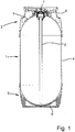
Figure 1 is a vertical section through a known keg as stood on a level surface; -
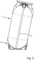
Figure 2 is a vertical section through the same keg which has been subject to heating under certain conditions; -
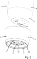
Figure 3 is an exploded general view of a modified bottom part of the keg; -
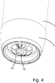
Figure 4 is a general view of the modified bottom part in the assembled keg; -
Figure 5 is a vertical section through the modified bottom part of the assembled keg; and -
Figure 6 is a general view of the bottom part of the assembled keg which incorporates a further modification. - Referring firstly to
Fig. 1 , a known form of keg for holding beverages such as beer includes acontainer 1 which is formed from plastics by blow moulding. An injection mouldedtop chime 2 is fixed to the top end of the container and an injection mouldedbottom chime 3 fixed to the opposite end. Thecontainer 1 has acylindrical side wall 4, atop wall 5 formed with acentral neck 6 containing a valve fitting 7 provided with adip tube 8. The dip tube terminates at the lowest part of abottom wall 9 which is of plain rounded shape. Thebottom chime 3 is fixed to the bottom wall of the container using a hot melt adhesive as the primary means of attachment. - Sometimes, for example if the kegs are stored at elevated temperatures when the kegs are tightly wrapped on a pallet, the adhesive can soften. The
container 1 can then become tilted over within thebottom chime 3, as shown inFig. 2 , so that the container no longer stands upright. This means that thedip tube 8, which is used to withdraw the contents of the keg, is no longer at the lowest part of the container and a small residual volume of liquid may remain in the keg. - In the modified keg shown in
Fig. 3 , during blow moulding thebottom wall 9 of thecontainer 1 is formed with a circular central projection orboss 10 which defines aninternal well 11 inside the container (seeFig. 5 ). Thebottom chime 3 has aninner hub 12 with acentral opening 13 and a plurality oflegs 14 which extend outwardly from the inner hub. Anouter skirt 15 fits over theside wall 4 of the container, with abottom rim 16 upon which the container stands, and aninner rim 17 which is joined to the outer ends of thelegs 14. Thecentral opening 13 of theinner hub 12 has the same internal profile as the outer profile of thecentral projection 10. When thebottom chime 3 is received on the bottom of thecontainer 1 as shown inFig. 4 , thecentral opening 13 receives thecentral projection 10, without fixation or interference, to locate the inner hub against lateral movement. Referring toFig. 5 , thebottom chime 3 is fixed to the bottom end of the container using a hot melt adhesive as the primary means of attachment which is applied toareas 20 of the bottom chime adjacent to theinner rim 17 of theouter skirt 12 and spaced from thecentral projection 10. As can also be seen inFig. 5 , the bottom end of thedip tube 8 extends into theinternal well 11 formed bycentral projection 10, which acts as a kind of sump. The lateral location provided by thecentral projection 10 thus prevents thecontainer 1 from tilting over within thebottom chime 3 and, even if no tilting has occurred, enables a greater quantity of liquid to be withdrawn via thedip tube 8 with little or no residual volume remaining, e.g. if the container is not stood on a level surface. - Due to manufacturing tolerances, or variations in pressure within the container, there may be axial variations between the positions of the
central projection 10 and theinner hub 12. In order to accommodate these variations and ensure that thecentral projection 10 is always fully located within the inner hub, thecentral opening 13 may be modified as shown inFig. 6 . Thecentral opening 13 incorporates a plurality ofslots 21 which radiate outwardly from thecentral projection 10, so that the slots define a plurality of flexible inwardly-directedfingers 22 which again locate the inner hub against lateral movement without fixation or interference. During assembly and adhesive fixation of thechime 3, thebottom wall 9 of the container may deform thefingers 22 in a downward direction to maintain a slight upward pressure on thebottom wall 9, thus ensuring that thecentral projection 10 is always properly located within thecentral opening 13. - It will be appreciated that the modified container retains the advantages of adhesive fixation whilst ensuring that the keg remains stable and upright under all conditions. The modification also enables a greater volume of liquid to be withdrawn under a wider range of conditions leaving a smaller residual volume.
the chime having:
Claims (3)
- A container assembly including a container (1) and a chime (2) fixed to each other;
the container having:- a peripheral side wall (4),- a top wall (5) formed with a central neck (6) containing a valve fitting (7) provided with a dip tube (8) which extends into the container, and- a bottom wall formed with a central projection (10), said central projection defining an internal well (11) inside the container;and
the chime having:- an inner hub (12) with a central opening (13),- a plurality of legs (14) extending outwardly from the inner hub, and- an outer skirt (15) joined to outer ends of the plurality of legs;in which the central opening (13) of the inner hub (12) receives the central projection (10) to locate the inner hub against lateral movement characterised in that- there is no fixation between the inner hub and the central projection;- the container (1) and the chime (2) are fixed to each other by means of an adhesive; and- a bottom end of the dip tube (8) extends into the internal well (11) of the central projection. - A container assembly according to Claim 1 in which the central opening (13) of the inner hub has the same internal profile as the outer profile of the central projection (10) to locate the inner hub against lateral movement without fixation between the inner hub and the central projection.
- A container assembly according to Claim 1 in which the central opening (13) of the inner hub incorporates a plurality of slots (21) which radiate outwardly from the central projection (10) and the plurality of slots define a plurality of flexible inwardly-directed fingers (22) which locate the inner hub against lateral movement without fixation between the inner hub and the central projection.
Applications Claiming Priority (2)
| Application Number | Priority Date | Filing Date | Title |
|---|---|---|---|
| GB1613495.9A GB2552712A (en) | 2016-08-05 | 2016-08-05 | Containers with adhesively attached chimes |
| PCT/GB2017/052243 WO2018025032A1 (en) | 2016-08-05 | 2017-08-02 | Containers with adhesively attached chimes |
Publications (2)
| Publication Number | Publication Date |
|---|---|
| EP3494057A1 EP3494057A1 (en) | 2019-06-12 |
| EP3494057B1 true EP3494057B1 (en) | 2020-11-04 |
Family
ID=59811690
Family Applications (1)
| Application Number | Title | Priority Date | Filing Date |
|---|---|---|---|
| EP17764432.5A Active EP3494057B1 (en) | 2016-08-05 | 2017-08-02 | Containers with adhesively attached chimes |
Country Status (6)
| Country | Link |
|---|---|
| US (1) | US20190177041A1 (en) |
| EP (1) | EP3494057B1 (en) |
| CN (1) | CN109890713A (en) |
| GB (1) | GB2552712A (en) |
| RU (1) | RU2019105728A (en) |
| WO (1) | WO2018025032A1 (en) |
Families Citing this family (2)
| Publication number | Priority date | Publication date | Assignee | Title |
|---|---|---|---|---|
| CH713614A1 (en) * | 2017-03-23 | 2018-09-28 | Alpla Werke Alwin Lehner Gmbh & Co Kg | Stand collar for an internal pressure-resistant plastic container, in particular for a plastic aerosol container, and equipped with a stand cuff aerosol container. |
| SE544653C2 (en) * | 2020-07-08 | 2022-10-04 | Aarke Ab | Beverage bottle and method for joining thereof |
Family Cites Families (8)
| Publication number | Priority date | Publication date | Assignee | Title |
|---|---|---|---|---|
| NL7305209A (en) * | 1972-04-17 | 1973-10-19 | ||
| JPS603071Y2 (en) * | 1981-03-05 | 1985-01-28 | サッポロビール株式会社 | Synthetic resin bottle |
| FR2816599B1 (en) * | 2000-11-10 | 2003-03-14 | Denis Delbarre | WAS LIQUID WITH PRESSURE CURING MEANS |
| EP2114780B1 (en) * | 2007-02-12 | 2013-04-03 | Anheuser-Busch InBev S.A. | Keg assembly and chime for being fixed to the bottom of a keg |
| GB2446393A (en) * | 2007-02-12 | 2008-08-13 | Inbev Sa | A Plastic Lower Chime and Keg Assembly for Beverage Kegs |
| GB2446392A (en) * | 2007-02-12 | 2008-08-13 | Inbev Sa | A Plastic Upper Chime and Keg Assembly for Beverage Kegs |
| US20090050598A1 (en) * | 2007-08-20 | 2009-02-26 | Chow-Chi Huang | Supportable pressurizable container and base cup therefor |
| US8439223B2 (en) * | 2007-08-20 | 2013-05-14 | The Procter & Gamble Company | Base cup for a supportable pressurizable container |
-
2016
- 2016-08-05 GB GB1613495.9A patent/GB2552712A/en not_active Withdrawn
-
2017
- 2017-08-02 EP EP17764432.5A patent/EP3494057B1/en active Active
- 2017-08-02 RU RU2019105728A patent/RU2019105728A/en not_active Application Discontinuation
- 2017-08-02 CN CN201780053216.6A patent/CN109890713A/en not_active Withdrawn
- 2017-08-02 US US16/323,064 patent/US20190177041A1/en not_active Abandoned
- 2017-08-02 WO PCT/GB2017/052243 patent/WO2018025032A1/en not_active Ceased
Non-Patent Citations (1)
| Title |
|---|
| None * |
Also Published As
| Publication number | Publication date |
|---|---|
| US20190177041A1 (en) | 2019-06-13 |
| WO2018025032A1 (en) | 2018-02-08 |
| RU2019105728A (en) | 2020-09-07 |
| EP3494057A1 (en) | 2019-06-12 |
| GB2552712A (en) | 2018-02-07 |
| CN109890713A (en) | 2019-06-14 |
Similar Documents
| Publication | Publication Date | Title |
|---|---|---|
| AU2010239438B2 (en) | Plastic beer keg | |
| EP2640646B1 (en) | Stackable container with a top chime | |
| US20200062443A1 (en) | Bottom Chime and Beverage Keg | |
| EP3494057B1 (en) | Containers with adhesively attached chimes | |
| US20110204062A1 (en) | Pressure vessel | |
| EP3386877B1 (en) | Container | |
| KR101420546B1 (en) | Disposable container with fitting attachment | |
| EP3318623A1 (en) | Pressure relief valve assembly for containers for fluids, and container provided with such valve assembly | |
| RU2783092C1 (en) | Chim for plastic keg | |
| US20250050362A1 (en) | Container with inset neck and discreet pump assembly | |
| WO2016180989A1 (en) | Pressure vessel | |
| RU97707U1 (en) | CAPACITY MANUFACTURED BY EXTRUSION OR INJECTION-BLASTING TECHNOLOGY (OPTIONS) |
Legal Events
| Date | Code | Title | Description |
|---|---|---|---|
| STAA | Information on the status of an ep patent application or granted ep patent |
Free format text: STATUS: UNKNOWN |
|
| STAA | Information on the status of an ep patent application or granted ep patent |
Free format text: STATUS: THE INTERNATIONAL PUBLICATION HAS BEEN MADE |
|
| PUAI | Public reference made under article 153(3) epc to a published international application that has entered the european phase |
Free format text: ORIGINAL CODE: 0009012 |
|
| STAA | Information on the status of an ep patent application or granted ep patent |
Free format text: STATUS: REQUEST FOR EXAMINATION WAS MADE |
|
| 17P | Request for examination filed |
Effective date: 20190220 |
|
| AK | Designated contracting states |
Kind code of ref document: A1 Designated state(s): AL AT BE BG CH CY CZ DE DK EE ES FI FR GB GR HR HU IE IS IT LI LT LU LV MC MK MT NL NO PL PT RO RS SE SI SK SM TR |
|
| AX | Request for extension of the european patent |
Extension state: BA ME |
|
| DAV | Request for validation of the european patent (deleted) | ||
| DAX | Request for extension of the european patent (deleted) | ||
| GRAP | Despatch of communication of intention to grant a patent |
Free format text: ORIGINAL CODE: EPIDOSNIGR1 |
|
| STAA | Information on the status of an ep patent application or granted ep patent |
Free format text: STATUS: GRANT OF PATENT IS INTENDED |
|
| INTG | Intention to grant announced |
Effective date: 20200609 |
|
| GRAS | Grant fee paid |
Free format text: ORIGINAL CODE: EPIDOSNIGR3 |
|
| GRAA | (expected) grant |
Free format text: ORIGINAL CODE: 0009210 |
|
| STAA | Information on the status of an ep patent application or granted ep patent |
Free format text: STATUS: THE PATENT HAS BEEN GRANTED |
|
| AK | Designated contracting states |
Kind code of ref document: B1 Designated state(s): AL AT BE BG CH CY CZ DE DK EE ES FI FR GB GR HR HU IE IS IT LI LT LU LV MC MK MT NL NO PL PT RO RS SE SI SK SM TR |
|
| REG | Reference to a national code |
Ref country code: GB Ref legal event code: FG4D |
|
| REG | Reference to a national code |
Ref country code: CH Ref legal event code: EP |
|
| REG | Reference to a national code |
Ref country code: AT Ref legal event code: REF Ref document number: 1330548 Country of ref document: AT Kind code of ref document: T Effective date: 20201115 |
|
| REG | Reference to a national code |
Ref country code: IE Ref legal event code: FG4D |
|
| REG | Reference to a national code |
Ref country code: DE Ref legal event code: R096 Ref document number: 602017026912 Country of ref document: DE |
|
| REG | Reference to a national code |
Ref country code: NL Ref legal event code: MP Effective date: 20201104 |
|
| REG | Reference to a national code |
Ref country code: AT Ref legal event code: MK05 Ref document number: 1330548 Country of ref document: AT Kind code of ref document: T Effective date: 20201104 |
|
| PG25 | Lapsed in a contracting state [announced via postgrant information from national office to epo] |
Ref country code: FI Free format text: LAPSE BECAUSE OF FAILURE TO SUBMIT A TRANSLATION OF THE DESCRIPTION OR TO PAY THE FEE WITHIN THE PRESCRIBED TIME-LIMIT Effective date: 20201104 Ref country code: GR Free format text: LAPSE BECAUSE OF FAILURE TO SUBMIT A TRANSLATION OF THE DESCRIPTION OR TO PAY THE FEE WITHIN THE PRESCRIBED TIME-LIMIT Effective date: 20210205 Ref country code: PT Free format text: LAPSE BECAUSE OF FAILURE TO SUBMIT A TRANSLATION OF THE DESCRIPTION OR TO PAY THE FEE WITHIN THE PRESCRIBED TIME-LIMIT Effective date: 20210304 Ref country code: RS Free format text: LAPSE BECAUSE OF FAILURE TO SUBMIT A TRANSLATION OF THE DESCRIPTION OR TO PAY THE FEE WITHIN THE PRESCRIBED TIME-LIMIT Effective date: 20201104 Ref country code: NO Free format text: LAPSE BECAUSE OF FAILURE TO SUBMIT A TRANSLATION OF THE DESCRIPTION OR TO PAY THE FEE WITHIN THE PRESCRIBED TIME-LIMIT Effective date: 20210204 |
|
| PG25 | Lapsed in a contracting state [announced via postgrant information from national office to epo] |
Ref country code: ES Free format text: LAPSE BECAUSE OF FAILURE TO SUBMIT A TRANSLATION OF THE DESCRIPTION OR TO PAY THE FEE WITHIN THE PRESCRIBED TIME-LIMIT Effective date: 20201104 Ref country code: AT Free format text: LAPSE BECAUSE OF FAILURE TO SUBMIT A TRANSLATION OF THE DESCRIPTION OR TO PAY THE FEE WITHIN THE PRESCRIBED TIME-LIMIT Effective date: 20201104 Ref country code: BG Free format text: LAPSE BECAUSE OF FAILURE TO SUBMIT A TRANSLATION OF THE DESCRIPTION OR TO PAY THE FEE WITHIN THE PRESCRIBED TIME-LIMIT Effective date: 20210204 Ref country code: PL Free format text: LAPSE BECAUSE OF FAILURE TO SUBMIT A TRANSLATION OF THE DESCRIPTION OR TO PAY THE FEE WITHIN THE PRESCRIBED TIME-LIMIT Effective date: 20201104 Ref country code: IS Free format text: LAPSE BECAUSE OF FAILURE TO SUBMIT A TRANSLATION OF THE DESCRIPTION OR TO PAY THE FEE WITHIN THE PRESCRIBED TIME-LIMIT Effective date: 20210304 Ref country code: LV Free format text: LAPSE BECAUSE OF FAILURE TO SUBMIT A TRANSLATION OF THE DESCRIPTION OR TO PAY THE FEE WITHIN THE PRESCRIBED TIME-LIMIT Effective date: 20201104 Ref country code: SE Free format text: LAPSE BECAUSE OF FAILURE TO SUBMIT A TRANSLATION OF THE DESCRIPTION OR TO PAY THE FEE WITHIN THE PRESCRIBED TIME-LIMIT Effective date: 20201104 |
|
| REG | Reference to a national code |
Ref country code: LT Ref legal event code: MG9D |
|
| PG25 | Lapsed in a contracting state [announced via postgrant information from national office to epo] |
Ref country code: HR Free format text: LAPSE BECAUSE OF FAILURE TO SUBMIT A TRANSLATION OF THE DESCRIPTION OR TO PAY THE FEE WITHIN THE PRESCRIBED TIME-LIMIT Effective date: 20201104 |
|
| PG25 | Lapsed in a contracting state [announced via postgrant information from national office to epo] |
Ref country code: SK Free format text: LAPSE BECAUSE OF FAILURE TO SUBMIT A TRANSLATION OF THE DESCRIPTION OR TO PAY THE FEE WITHIN THE PRESCRIBED TIME-LIMIT Effective date: 20201104 Ref country code: RO Free format text: LAPSE BECAUSE OF FAILURE TO SUBMIT A TRANSLATION OF THE DESCRIPTION OR TO PAY THE FEE WITHIN THE PRESCRIBED TIME-LIMIT Effective date: 20201104 Ref country code: SM Free format text: LAPSE BECAUSE OF FAILURE TO SUBMIT A TRANSLATION OF THE DESCRIPTION OR TO PAY THE FEE WITHIN THE PRESCRIBED TIME-LIMIT Effective date: 20201104 Ref country code: EE Free format text: LAPSE BECAUSE OF FAILURE TO SUBMIT A TRANSLATION OF THE DESCRIPTION OR TO PAY THE FEE WITHIN THE PRESCRIBED TIME-LIMIT Effective date: 20201104 Ref country code: CZ Free format text: LAPSE BECAUSE OF FAILURE TO SUBMIT A TRANSLATION OF THE DESCRIPTION OR TO PAY THE FEE WITHIN THE PRESCRIBED TIME-LIMIT Effective date: 20201104 Ref country code: LT Free format text: LAPSE BECAUSE OF FAILURE TO SUBMIT A TRANSLATION OF THE DESCRIPTION OR TO PAY THE FEE WITHIN THE PRESCRIBED TIME-LIMIT Effective date: 20201104 |
|
| REG | Reference to a national code |
Ref country code: DE Ref legal event code: R097 Ref document number: 602017026912 Country of ref document: DE |
|
| PG25 | Lapsed in a contracting state [announced via postgrant information from national office to epo] |
Ref country code: DK Free format text: LAPSE BECAUSE OF FAILURE TO SUBMIT A TRANSLATION OF THE DESCRIPTION OR TO PAY THE FEE WITHIN THE PRESCRIBED TIME-LIMIT Effective date: 20201104 |
|
| PLBE | No opposition filed within time limit |
Free format text: ORIGINAL CODE: 0009261 |
|
| STAA | Information on the status of an ep patent application or granted ep patent |
Free format text: STATUS: NO OPPOSITION FILED WITHIN TIME LIMIT |
|
| 26N | No opposition filed |
Effective date: 20210805 |
|
| PG25 | Lapsed in a contracting state [announced via postgrant information from national office to epo] |
Ref country code: NL Free format text: LAPSE BECAUSE OF FAILURE TO SUBMIT A TRANSLATION OF THE DESCRIPTION OR TO PAY THE FEE WITHIN THE PRESCRIBED TIME-LIMIT Effective date: 20201104 Ref country code: AL Free format text: LAPSE BECAUSE OF FAILURE TO SUBMIT A TRANSLATION OF THE DESCRIPTION OR TO PAY THE FEE WITHIN THE PRESCRIBED TIME-LIMIT Effective date: 20201104 |
|
| PGFP | Annual fee paid to national office [announced via postgrant information from national office to epo] |
Ref country code: FR Payment date: 20210810 Year of fee payment: 5 |
|
| PG25 | Lapsed in a contracting state [announced via postgrant information from national office to epo] |
Ref country code: SI Free format text: LAPSE BECAUSE OF FAILURE TO SUBMIT A TRANSLATION OF THE DESCRIPTION OR TO PAY THE FEE WITHIN THE PRESCRIBED TIME-LIMIT Effective date: 20201104 |
|
| PGFP | Annual fee paid to national office [announced via postgrant information from national office to epo] |
Ref country code: DE Payment date: 20210818 Year of fee payment: 5 Ref country code: BE Payment date: 20210812 Year of fee payment: 5 |
|
| REG | Reference to a national code |
Ref country code: CH Ref legal event code: PL |
|
| PG25 | Lapsed in a contracting state [announced via postgrant information from national office to epo] |
Ref country code: MC Free format text: LAPSE BECAUSE OF FAILURE TO SUBMIT A TRANSLATION OF THE DESCRIPTION OR TO PAY THE FEE WITHIN THE PRESCRIBED TIME-LIMIT Effective date: 20201104 |
|
| PG25 | Lapsed in a contracting state [announced via postgrant information from national office to epo] |
Ref country code: LI Free format text: LAPSE BECAUSE OF NON-PAYMENT OF DUE FEES Effective date: 20210831 Ref country code: CH Free format text: LAPSE BECAUSE OF NON-PAYMENT OF DUE FEES Effective date: 20210831 |
|
| PG25 | Lapsed in a contracting state [announced via postgrant information from national office to epo] |
Ref country code: IS Free format text: LAPSE BECAUSE OF FAILURE TO SUBMIT A TRANSLATION OF THE DESCRIPTION OR TO PAY THE FEE WITHIN THE PRESCRIBED TIME-LIMIT Effective date: 20210304 Ref country code: LU Free format text: LAPSE BECAUSE OF NON-PAYMENT OF DUE FEES Effective date: 20210802 |
|
| PG25 | Lapsed in a contracting state [announced via postgrant information from national office to epo] |
Ref country code: IE Free format text: LAPSE BECAUSE OF NON-PAYMENT OF DUE FEES Effective date: 20210802 |
|
| REG | Reference to a national code |
Ref country code: DE Ref legal event code: R119 Ref document number: 602017026912 Country of ref document: DE |
|
| REG | Reference to a national code |
Ref country code: BE Ref legal event code: MM Effective date: 20220831 |
|
| PG25 | Lapsed in a contracting state [announced via postgrant information from national office to epo] |
Ref country code: CY Free format text: LAPSE BECAUSE OF FAILURE TO SUBMIT A TRANSLATION OF THE DESCRIPTION OR TO PAY THE FEE WITHIN THE PRESCRIBED TIME-LIMIT Effective date: 20201104 |
|
| PG25 | Lapsed in a contracting state [announced via postgrant information from national office to epo] |
Ref country code: HU Free format text: LAPSE BECAUSE OF FAILURE TO SUBMIT A TRANSLATION OF THE DESCRIPTION OR TO PAY THE FEE WITHIN THE PRESCRIBED TIME-LIMIT; INVALID AB INITIO Effective date: 20170802 Ref country code: FR Free format text: LAPSE BECAUSE OF NON-PAYMENT OF DUE FEES Effective date: 20220831 Ref country code: DE Free format text: LAPSE BECAUSE OF NON-PAYMENT OF DUE FEES Effective date: 20230301 |
|
| PG25 | Lapsed in a contracting state [announced via postgrant information from national office to epo] |
Ref country code: BE Free format text: LAPSE BECAUSE OF NON-PAYMENT OF DUE FEES Effective date: 20220831 |
|
| PG25 | Lapsed in a contracting state [announced via postgrant information from national office to epo] |
Ref country code: MK Free format text: LAPSE BECAUSE OF FAILURE TO SUBMIT A TRANSLATION OF THE DESCRIPTION OR TO PAY THE FEE WITHIN THE PRESCRIBED TIME-LIMIT Effective date: 20201104 |
|
| PG25 | Lapsed in a contracting state [announced via postgrant information from national office to epo] |
Ref country code: TR Free format text: LAPSE BECAUSE OF FAILURE TO SUBMIT A TRANSLATION OF THE DESCRIPTION OR TO PAY THE FEE WITHIN THE PRESCRIBED TIME-LIMIT Effective date: 20201104 |
|
| PG25 | Lapsed in a contracting state [announced via postgrant information from national office to epo] |
Ref country code: MT Free format text: LAPSE BECAUSE OF FAILURE TO SUBMIT A TRANSLATION OF THE DESCRIPTION OR TO PAY THE FEE WITHIN THE PRESCRIBED TIME-LIMIT Effective date: 20201104 |
|
| PGFP | Annual fee paid to national office [announced via postgrant information from national office to epo] |
Ref country code: IT Payment date: 20250827 Year of fee payment: 9 |
|
| PGFP | Annual fee paid to national office [announced via postgrant information from national office to epo] |
Ref country code: GB Payment date: 20250926 Year of fee payment: 9 |