EP3494032B1 - Track system for a work vehicle - Google Patents
Track system for a work vehicle Download PDFInfo
- Publication number
- EP3494032B1 EP3494032B1 EP17748461.5A EP17748461A EP3494032B1 EP 3494032 B1 EP3494032 B1 EP 3494032B1 EP 17748461 A EP17748461 A EP 17748461A EP 3494032 B1 EP3494032 B1 EP 3494032B1
- Authority
- EP
- European Patent Office
- Prior art keywords
- roller
- track
- rockers
- wheels
- rocker
- Prior art date
- Legal status (The legal status is an assumption and is not a legal conclusion. Google has not performed a legal analysis and makes no representation as to the accuracy of the status listed.)
- Active
Links
Images


Classifications
-
- B—PERFORMING OPERATIONS; TRANSPORTING
- B62—LAND VEHICLES FOR TRAVELLING OTHERWISE THAN ON RAILS
- B62D—MOTOR VEHICLES; TRAILERS
- B62D55/00—Endless track vehicles
- B62D55/08—Endless track units; Parts thereof
- B62D55/104—Suspension devices for wheels, rollers, bogies or frames
- B62D55/108—Suspension devices for wheels, rollers, bogies or frames with mechanical springs, e.g. torsion bars
-
- B—PERFORMING OPERATIONS; TRANSPORTING
- B62—LAND VEHICLES FOR TRAVELLING OTHERWISE THAN ON RAILS
- B62D—MOTOR VEHICLES; TRAILERS
- B62D55/00—Endless track vehicles
- B62D55/06—Endless track vehicles with tracks without ground wheels
- B62D55/065—Multi-track vehicles, i.e. more than two tracks
-
- B—PERFORMING OPERATIONS; TRANSPORTING
- B62—LAND VEHICLES FOR TRAVELLING OTHERWISE THAN ON RAILS
- B62D—MOTOR VEHICLES; TRAILERS
- B62D55/00—Endless track vehicles
- B62D55/08—Endless track units; Parts thereof
- B62D55/084—Endless-track units or carriages mounted separably, adjustably or extensibly on vehicles, e.g. portable track units
-
- B—PERFORMING OPERATIONS; TRANSPORTING
- B62—LAND VEHICLES FOR TRAVELLING OTHERWISE THAN ON RAILS
- B62D—MOTOR VEHICLES; TRAILERS
- B62D55/00—Endless track vehicles
- B62D55/08—Endless track units; Parts thereof
- B62D55/104—Suspension devices for wheels, rollers, bogies or frames
- B62D55/108—Suspension devices for wheels, rollers, bogies or frames with mechanical springs, e.g. torsion bars
- B62D55/1086—Rubber springs
Definitions
- the present invention relates to a track system for a tracked work vehicle, such as a construction equipment vehicle or a military tracked vehicle or an agricultural vehicle, e.g. a combined harvester or the like.
- a tracked work vehicle such as a construction equipment vehicle or a military tracked vehicle or an agricultural vehicle, e.g. a combined harvester or the like.
- a tracked work vehicle is provided with a suspension in order to increase adhesion and traction performances on soft grounds, such as grounds affected by a relatively high degree of humidity or grounds having a relatively high quantity of sand.
- a rubber tracked vehicle is preferred to satisfy the need for a relatively high speed on paved streets, e.g. during a travel of the work vehicle to and from a construction site or a cultivated field. Furthermore, a rubber track tends to be relatively less expensive than other tracks.
- the suspension is normally an undercarriage suspension and provides the highest traction performances when the track adheres the ground.
- the surface layer of the ground is not uniform and bodies made of a hard material are found on or immediately below the surface of the ground, such as rocks, spare metallic construction materials such as tubes or the like.
- DE578902 discloses a tracked system for a work vehicle, in which the stiffness and kinematic compliance is provided on the stiffness side , this solution does not provide a reduced excessive wear out of insufficient constrained rollers.
- intermediate rocker is connected to the undercarriage beam via the first and the second rockers.
- the elastic or visco-elastic connection is a bushing.
- At least one roller wheel comprises a first and a second wheel, and a shaft to connect first and second wheels, the shaft being pivotally attached to a relevant rocker.
- an existing tracked vehicle is retrofittable or can be provided with a linkage according to the present invention during a periodic maintenance.
- Figure 1 refers, as a whole, to a work vehicle 1 comprising a frame 2 and at least two rubber tracked, preferably four, track systems 3 attached to frame 2.
- Frame 2 can be a rigid frame and in this case the vehicle may be provided with steering wheels (not shown); or a hinged frame having a front part 4, a rear part 5 hinged to front part 4 about axis A and a steering unit (not shown), preferably a hydraulic steering unit comprising linear actuators, to control the relative angular position of front part 4 with respect to rear part 5 about axis A.
- a steering unit preferably a hydraulic steering unit comprising linear actuators
- Each track system 3 comprises a rubber track 6, a drive wheel 7 extending from a differential (not shown) for driving track 6 and an undercarriage 8 pivoting with respect to frame 2.
- Undercarriage 8 comprises a front idler wheel 9, a rear idler wheel 10 about which track 6 is wrapped, roller wheels 11, 12, 13 for guiding track 6, all of which are supported by an undercarriage beam 14, which extends fore-and-aft, and to which wheels 11, 12, 9 and 10 are coupled.
- the "front idler wheel,” “rear idler wheel,” “roller wheel” are singular terms, a plurality of wheels may be provided at each relative position in side-to-side orientation, such as in this embodiment.
- at least wheels 11, 12, 13, 9 and 10 are twin wheels, i.e. each wheel comprises two wheels coupled side-to-side.
- undercarriage beam 14 is connected to frame 2 in order to tilt in a plane parallel to axis A and oriented fore-and-aft when vehicle 1 travels along a straight path.
- Preferably undercarriage beam 14 is hinged to frame 2 in order to tilt for a maximum of 15 degrees with respect to a neutral position shown in figure 1 .
- drive wheel 7 is fixed to frame 2.
- Each track system 3 further comprises a tilting linkage 15 to connect roller wheels 11, 12, 13 to undercarriage beam 14 in order to provide one or more degrees of freedom to such rollers with respect to beam 14.
- linkage 15 comprises a rigid rocker 20, 21, 22 connected to a respective roller wheel 11, 12, 13.
- Rigid rockers 20, 22 are respectively adjacent to idler 9 and idler 10 and hinged to beam 14.
- Rocker 21 is longitudinally placed between rockers 20, 22 and is connected to beam 14 via rockers 20, 22. Therefore intermediate rocker 21 is floating with respect to beam 14.
- track system 3 comprises at least one elastic or visco-elastic connection 23 to connect rockers 20, 22 to rocker 21 in such a way that an upwards motion of a leading roller, e.g. roller wheel 11 during climbing an obstacle 24, applies a downwards action on both trailing rollers 12 and 13, such action being transmitted through the elastic or visco-elastic connections 23.
- a leading roller e.g. roller wheel 11 during climbing an obstacle 24
- tracks system 3 comprises at least one elastic or visco-elastic connection 23 to connect rockers 20, 22 to rocker 21 in such a way that an upwards motion of a leading roller, e.g. roller wheel 11 during climbing an obstacle 24, applies a downwards action on both trailing rollers 12 and 13, such action being transmitted through the elastic or visco-elastic connections 23.
- Such functioning is obtained via the floating connection of intermediate rocker 21 to beam 14, which is operated only via rockers 20, 22.
- the distance and relative position of each hinge and center of roller wheels 11, 12, 13 within linkage 15 provides a different distribution of forces
- connection can be either passive, i.e. including a spring and a damper that are pre-set during assembly or by the user before a specific mission of vehicle 1, or active, i.e. including actuators to change the spring modulus or stiffness and/or the damping of the connection when vehicle 1 is working.
- connection is visco-elastic and comprises inserts, e.g. a pack of discs, or bushings of a rubber material possibly reinforced either by particles or fibres or by one or more woven or non-woven layers. Rubber inserts or bushings are loaded to transfer the target action by either compression or shear or a combination of the two.
- inserts e.g. a pack of discs, or bushings of a rubber material possibly reinforced either by particles or fibres or by one or more woven or non-woven layers. Rubber inserts or bushings are loaded to transfer the target action by either compression or shear or a combination of the two.
- each rocker 20, 22 comprises a first end portion 25 carrying a relative roller 11, 13 and a second end portion 26 projecting on an opposite side of the first end portion with respect to a hinge 27 for connection of the rocker to undercarriage beam 14.
- Rockers 20, 22 are specular with respect to intermediate rocker 21 ( figure 2 ) so that rollers 11, 13 are opposite to respective hinge 27 with respect to intermediate rocker 21.
- Intermediate rocker 21 is preferably symmetrical with respect to a plan comprising the axis of roller 12 but other configurations are possible.
- connections 23 apply the respective loads on points that are symmetrical with respect to the plane comprising the axis of roller 12.
- rockers 20, 21, 22 are located below the undercarriage beam 14 and hinges 27 for connection with rockers 20, 22 are defined by stirrups 28 extending from beam 14 towards the ground opposite to driving wheel 7. Furthermore, rockers 20, 21, 22 are hinged one to the other. To do so, first and second end portions 25, 26 of rockers 20, 22 define an angle between 90° and 180° and hinge 27 is located in a vertex portion 29 of rockers 20, 22 formed between first and second end portions 25, 26.
- the elastic or visco-elastic connection 23 is located below undercarriage beam 14 and comprises a rubber bushing mounted in hinge 31 for connection between two adjacent rockers 20, 21, 22.
- the shape of rockers 20, 21, 22 and the position of hinges 27 and 31 is such to provide a kinematically fixed configuration when loaded on a geometric plane.
- the rubber bushing 23 were substituted by a rigid body, rollers 11, 12, 13 and rockers 20, 21, 22 could not move one with respect to the other.
- the provision of rubber bushings 23 in hinges 31 and optionally also in hinges 27 provides, by means of compression of the bushings depending on the obstacles encountered by track 6, relatives degrees of freedom between rockers 20, 21, 22 and, accordingly, between rollers 11, 12, 13.
- Such configuration therefore provides kinematic liability only in view of the fact that rubber bushings 23 are deformable. This results in a relatively stiff configuration of the suspension, i.e. the combination of tilting supports and elastic or visco-elastic connection.
- rollers 11, 12, 13 comprise a first and a second wheel 60, 61 rigidly connected one to the other by a shaft 62.
- Each shaft 62 is pivotably attached to first end portion 25 of the relative rocker 20, 22 or to rocker 21, preferably in the plane of symmetry, in order to provide a rotational degree of freedom about an axis A that is co-planar to a mid-plane of track 6 and/or of shaft 62.
- pivoting axis of shaft 62 is defined by a pin (not shown), in particular a screwable pin, attached in a dedicated seat within first end portion 25.
- Shaft 62 is attached to the pin.
- a resilient element acts on shaft 62.
- resilient element is housed at least in part or wholly within first end portion 25.
- the resilient element comprises rubber bushings, or a pack of rubber discs or the like and is coaxial to shaft 62.
- elastic or visco-elastic connection 23 is designed such that, when travelling on a paved street, at least front idler wheel 9, preferably also idler wheel 10, are lifted from the paved surface. Without a prejudice to the stability of the work vehicle, this decreases wear on rubber track 6.
- rockers connected one to the other by elastic or visco-elastic connections provides the combined effect of increasing effectiveness to overcome obstacles and, at the same time, reduce the wear of the track.
- a controlled compliance of the rollers is such to avoid tension peaks within the track when the ground is rough or non-homogeneous.
- the linkage 15 is such to provide that both trailing rollers 12, 13 a load that presses track 6 down when leading roller 11 climbs obstacle 24.
- Connections 23 located below undercarriage beam 14 provide the lowest possible impact on undercarriage beam.
- track 6 can be arranged along a triangular path, as shown e.g. in figure 1 , or along other paths. This may increase or reduce the number of idler wheels with respect to the embodiments discussed in the preceding paragraphs.
- two rollers may be attached to a single intermediate rocker such as e.g. a walking beam, in order to rigidly tilt one with respect to the other when track 6 runs on an obstacle 23.
- a single intermediate rocker such as e.g. a walking beam
- connection 23 is a rubber block, preferably a reinforced rubber block, defining a deformable spacer between adjacent rockers 20, 21, 22 according to the sketch of figure 2 .
- the rubber block is compressed when adjacent rockers rotate in opposite angular directions.
- the rubber block shall have suitable dimensions.
- the rubber block is located below undercarriage beam 14 and is preferably carried by the relevant rockers 20, 21, 22. Conveniently the rubber block is interference fitted between second end portions 26 an intermediate rocker 21 in order to provide, after mounting, a tensioning action on track 6.
- the rubber block is preferably attached to one of the adjacent rockers and abuts without being attached to the other of the adjacent rockers.
- connection 23 be a link comprising a single elastic or visco-elastic element, in particular a linear single elastic or visco-elastic element or damper.
- connection 23 comprises a rubber block compressed by rockers 20, 22.
Landscapes
- Engineering & Computer Science (AREA)
- Chemical & Material Sciences (AREA)
- Combustion & Propulsion (AREA)
- Transportation (AREA)
- Mechanical Engineering (AREA)
- Body Structure For Vehicles (AREA)
- Tires In General (AREA)
- Vehicle Body Suspensions (AREA)
Description
- The present invention relates to a track system for a tracked work vehicle, such as a construction equipment vehicle or a military tracked vehicle or an agricultural vehicle, e.g. a combined harvester or the like.
- A tracked work vehicle is provided with a suspension in order to increase adhesion and traction performances on soft grounds, such as grounds affected by a relatively high degree of humidity or grounds having a relatively high quantity of sand.
- A rubber tracked vehicle is preferred to satisfy the need for a relatively high speed on paved streets, e.g. during a travel of the work vehicle to and from a construction site or a cultivated field. Furthermore, a rubber track tends to be relatively less expensive than other tracks.
- The suspension is normally an undercarriage suspension and provides the highest traction performances when the track adheres the ground. Sometimes the surface layer of the ground is not uniform and bodies made of a hard material are found on or immediately below the surface of the ground, such as rocks, spare metallic construction materials such as tubes or the like.
DE578902 discloses a tracked system for a work vehicle, in which the stiffness and kinematic compliance is provided on the stiffness side , this solution does not provide a reduced excessive wear out of insufficient constrained rollers. - When encountering such an obstacle, it is important to find a compromise between stiffness and kinematic compliance for the design of the track-supporting idlers, rollers and structure of the suspension. Otherwise the track, in particular the rubber track, may undergo excessive wear. In particular it is important that the rollers are sufficiently constrained to provide proper support to the track when the ground is uniformly soft and are mobile enough to retract only in the near surroundings of a hard body on the ground surface. In both instances the scope is to keep or improve traction performances and, at the same time, lower the wear of the track.
- The scope of the present invention is achieved by a rubber tracked work vehicle according to claim 1.
- According to a preferred embodiment, intermediate rocker is connected to the undercarriage beam via the first and the second rockers.
- According to another preferred embodiment the elastic or visco-elastic connection is a bushing.
- According to another preferred embodiment at least one roller wheel comprises a first and a second wheel, and a shaft to connect first and second wheels, the shaft being pivotally attached to a relevant rocker.
- According to the invention, an existing tracked vehicle is retrofittable or can be provided with a linkage according to the present invention during a periodic maintenance.
- Additional features of the invention are disclosed in the description and the dependent claims.
- For a better understanding of the present invention, the latter will further be disclosed with reference to the accompanying figures in which:
-
Figure 1 shows a work vehicle that can be equipped with the present invention; -
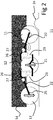
Figure 2 is a sketch of a linkage for the vehicle offigure 1 ; -
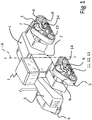
Figure 3 is a bottom enlarged perspective view of an embodiment of the linkage offigure 2 . Some elements are cancelled for clarity's sake; and -
Figure 4 is a lateral enlarged perspective view offigure 3 . -
Figure 1 refers, as a whole, to a work vehicle 1 comprising aframe 2 and at least two rubber tracked, preferably four,track systems 3 attached toframe 2. -
Frame 2 can be a rigid frame and in this case the vehicle may be provided with steering wheels (not shown); or a hinged frame having afront part 4, a rear part 5 hinged tofront part 4 about axis A and a steering unit (not shown), preferably a hydraulic steering unit comprising linear actuators, to control the relative angular position offront part 4 with respect to rear part 5 about axis A. - Each
track system 3 comprises arubber track 6, adrive wheel 7 extending from a differential (not shown) fordriving track 6 and anundercarriage 8 pivoting with respect toframe 2. Undercarriage 8 comprises afront idler wheel 9, arear idler wheel 10 about whichtrack 6 is wrapped,roller wheels track 6, all of which are supported by anundercarriage beam 14, which extends fore-and-aft, and to whichwheels rubber track 6, at leastwheels - In
particular undercarriage beam 14 is connected toframe 2 in order to tilt in a plane parallel to axis A and oriented fore-and-aft when vehicle 1 travels along a straight path. Preferablyundercarriage beam 14 is hinged toframe 2 in order to tilt for a maximum of 15 degrees with respect to a neutral position shown infigure 1 . Instead drivewheel 7 is fixed toframe 2. - Each
track system 3 further comprises a tiltinglinkage 15 to connectroller wheels beam 14 in order to provide one or more degrees of freedom to such rollers with respect tobeam 14. In particular,linkage 15 comprises arigid rocker respective roller wheel Rigid rockers idler 9 andidler 10 and hinged tobeam 14. Rocker 21 is longitudinally placed betweenrockers beam 14 viarockers intermediate rocker 21 is floating with respect tobeam 14. - In addition,
track system 3 comprises at least one elastic or visco-elastic connection 23 to connectrockers e.g. roller wheel 11 during climbing anobstacle 24, applies a downwards action on bothtrailing rollers elastic connections 23. Such functioning is obtained via the floating connection ofintermediate rocker 21 tobeam 14, which is operated only viarockers roller wheels linkage 15 provides a different distribution of forces on rollers. - Preferably, the position of
roller wheels track 6 is such to increase the tension of the track after mounting of the latter aboutdrive wheel 7 andidler wheels - Preferably, the connection is visco-elastic and comprises inserts, e.g. a pack of discs, or bushings of a rubber material possibly reinforced either by particles or fibres or by one or more woven or non-woven layers. Rubber inserts or bushings are loaded to transfer the target action by either compression or shear or a combination of the two.
- According to the functional sketch of
figure 2 , eachrocker first end portion 25 carrying arelative roller second end portion 26 projecting on an opposite side of the first end portion with respect to ahinge 27 for connection of the rocker toundercarriage beam 14.Rockers figure 2 ) so thatrollers respective hinge 27 with respect tointermediate rocker 21.Intermediate rocker 21 is preferably symmetrical with respect to a plan comprising the axis ofroller 12 but other configurations are possible. According to thepresent embodiment connections 23 apply the respective loads on points that are symmetrical with respect to the plane comprising the axis ofroller 12. - When
roller 12 is leading roller,obstacle 24 liftsintermediate rocker 21 and this causes bothrockers respective trailing rollers - According to a preferred embodiment of the invention (
figure 3 ),rockers undercarriage beam 14 and hinges 27 for connection withrockers stirrups 28 extending frombeam 14 towards the ground opposite to drivingwheel 7. Furthermore,rockers second end portions rockers hinge 27 is located in avertex portion 29 ofrockers second end portions - Furthermore the elastic or visco-
elastic connection 23 is located belowundercarriage beam 14 and comprises a rubber bushing mounted inhinge 31 for connection between twoadjacent rockers rockers hinges rubber bushing 23 were substituted by a rigid body,rollers rockers rubber bushings 23 inhinges 31 and optionally also inhinges 27 provides, by means of compression of the bushings depending on the obstacles encountered bytrack 6, relatives degrees of freedom betweenrockers rollers rubber bushings 23 are deformable. This results in a relatively stiff configuration of the suspension, i.e. the combination of tilting supports and elastic or visco-elastic connection. - As a further feature shown in the drawings,
rollers second wheel shaft 62. Eachshaft 62 is pivotably attached tofirst end portion 25 of therelative rocker rocker 21, preferably in the plane of symmetry, in order to provide a rotational degree of freedom about an axis A that is co-planar to a mid-plane oftrack 6 and/or ofshaft 62. - Preferably (
figure 4 ), pivoting axis ofshaft 62 is defined by a pin (not shown), in particular a screwable pin, attached in a dedicated seat withinfirst end portion 25.Shaft 62 is attached to the pin. In order to restore a neutral position, i.e. a position whereinshaft 62 is substantially parallel to axes ofdrive wheel 7 andidler wheels shaft 62. Preferably resilient element is housed at least in part or wholly withinfirst end portion 25. According to one embodiment, the resilient element comprises rubber bushings, or a pack of rubber discs or the like and is coaxial toshaft 62. - It is preferable that elastic or visco-
elastic connection 23 is designed such that, when travelling on a paved street, at least frontidler wheel 9, preferably alsoidler wheel 10, are lifted from the paved surface. Without a prejudice to the stability of the work vehicle, this decreases wear onrubber track 6. - The advantages of an undercarriage suspension according to the present invention are the following.
- The provision of rockers connected one to the other by elastic or visco-elastic connections provides the combined effect of increasing effectiveness to overcome obstacles and, at the same time, reduce the wear of the track. Indeed a controlled compliance of the rollers is such to avoid tension peaks within the track when the ground is rough or non-homogeneous. This is in particular true where the
linkage 15 is such to provide that both trailingrollers 12, 13 a load that pressestrack 6 down when leadingroller 11 climbsobstacle 24. -
Connections 23 located belowundercarriage beam 14 provide the lowest possible impact on undercarriage beam. - It is clear that changes and variations are applicable to the work vehicle according to the present invention without departing from the scope of protection as defined in the attached claims.
- For example,
track 6 can be arranged along a triangular path, as shown e.g. infigure 1 , or along other paths. This may increase or reduce the number of idler wheels with respect to the embodiments discussed in the preceding paragraphs. - When at least three rollers are provided to guide
track 6, two rollers may be attached to a single intermediate rocker such as e.g. a walking beam, in order to rigidly tilt one with respect to the other whentrack 6 runs on anobstacle 23. - It is possible to retrofit existing work vehicles with a kit comprising at least the
undercarriage beam 14,rockers connection 23. - According to a further not shown
embodiment connection 23 is a rubber block, preferably a reinforced rubber block, defining a deformable spacer betweenadjacent rockers figure 2 . The rubber block is compressed when adjacent rockers rotate in opposite angular directions. In order to provide proper absorption and/or load resistance, the rubber block shall have suitable dimensions. - The rubber block is located below
undercarriage beam 14 and is preferably carried by therelevant rockers second end portions 26 anintermediate rocker 21 in order to provide, after mounting, a tensioning action ontrack 6. The rubber block is preferably attached to one of the adjacent rockers and abuts without being attached to the other of the adjacent rockers. - It is possible that
connection 23 be a link comprising a single elastic or visco-elastic element, in particular a linear single elastic or visco-elastic element or damper. - As an alternative,
connection 23 comprises a rubber block compressed byrockers
Claims (8)
- A tracked system for a work vehicle comprising a suspension (3) having a driving wheel (7), an undercarriage beam (14) hinged to a frame (2) of the vehicle, at least one idler wheel (9), at least a first, a second and a third roller wheels (11, 12, 13) attached to the undercarriage beam (14) and a rubber track (6) wound about at least driving wheel (7), idler wheel (9), roller wheels (11, 12, 13), characterized by comprising a tilting linkage (15) having a first and a second rocker (20, 22) to attach first and third roller wheels (11, 13) to the undercarriage beam (14) and an intermediate rocker (21) to attach the second roller (12) to the first and third rollers (11, 13) so that first and second roller wheels (11, 12) are movable one with respect to the other at least in certain working conditions, and an elastic or visco-elastic connection (23) to connect intermediate rocker (21) to first and second rockers (20, 22) such that the intermediate rocker (21) is longitudinally placed between the rockers (20, 22) and is connected to the beam (14) via the rockers (20, 22) such that the intermediate rocker (21) is floating with respect to the beam (14) and such that a load applied to one roller wheel (11) transfers to both other rollers (12, 13) through the connection (23) to increase the pressure uniformity of the track on the ground.
- Track system according to either claim 1, wherein the connection (23) is a bushing parallel with a hinge (27) between the intermediate rocker (21) and at least one of the first and second rockers (20, 22).
- Track system according to any of the preceding claims, wherein the connection (23) is located below the undercarriage beam (14).
- Track system according to any of the preceding claims, wherein the linkage (15) is symmetric with respect to a plane comprising the axis of the second roller wheel (12).
- Track system according to any of the preceding claims, wherein at least one roller wheel comprises a first and a second wheels (60, 61), and a shaft (62) to connect first and second wheels (60, 61), the shaft being pivotally attached to a relevant rocker (20, 22).
- Track system according to claim 5, wherein a neutral position of the shaft (62) is resiliently restored such that the shaft is substantially parallel to axes of the idler wheel and/or the driving wheel (9, 7).
- Method of retrofitting a work vehicle with a track system (3) according to any of the preceding claims.
- Method according to claim 7, wherein the roller wheels (11, 12, 13) are twin wheels.
Applications Claiming Priority (2)
| Application Number | Priority Date | Filing Date | Title |
|---|---|---|---|
| IT102016000081211A IT201600081211A1 (en) | 2016-08-02 | 2016-08-02 | TRACK SYSTEM FOR WORKING VEHICLE |
| PCT/EP2017/069512 WO2018024766A2 (en) | 2016-08-02 | 2017-08-02 | Track system for a work vehicle |
Publications (2)
| Publication Number | Publication Date |
|---|---|
| EP3494032A2 EP3494032A2 (en) | 2019-06-12 |
| EP3494032B1 true EP3494032B1 (en) | 2020-10-07 |
Family
ID=58638913
Family Applications (1)
| Application Number | Title | Priority Date | Filing Date |
|---|---|---|---|
| EP17748461.5A Active EP3494032B1 (en) | 2016-08-02 | 2017-08-02 | Track system for a work vehicle |
Country Status (4)
| Country | Link |
|---|---|
| EP (1) | EP3494032B1 (en) |
| CN (1) | CN109562798B (en) |
| IT (1) | IT201600081211A1 (en) |
| WO (1) | WO2018024766A2 (en) |
Families Citing this family (7)
| Publication number | Priority date | Publication date | Assignee | Title |
|---|---|---|---|---|
| IT201800002954A1 (en) * | 2018-02-22 | 2019-08-22 | Cnh Ind Italia Spa | SUSPENSION SYSTEM FOR A TRACKED TRANSMISSION |
| IT201800003244A1 (en) * | 2018-03-02 | 2019-09-02 | Prinoth Spa | TRACKED VEHICLE FOR THE PREPARATION OF SKI SLOPES |
| US11618515B2 (en) | 2019-04-09 | 2023-04-04 | Cnh Industrial America Llc | Suspension system for a track-driven work vehicle with tandem rear idler/roller |
| US11753093B2 (en) | 2019-04-09 | 2023-09-12 | Cnh Industrial America Llc | Suspension system for a track-driven work vehicle with pivoting roller wheel assemblies |
| CN113101587B (en) * | 2020-12-21 | 2022-04-15 | 沃优集团有限公司 | Security protection inspection robot |
| CN113117121B (en) * | 2021-05-19 | 2023-04-25 | 长江师范学院 | Crawler-type wheel traveling system and environment disinfection dolly thereof |
| CN114537543B (en) * | 2022-04-26 | 2022-06-28 | 成都航空职业技术学院 | All-terrain walking robot |
Family Cites Families (17)
| Publication number | Priority date | Publication date | Assignee | Title |
|---|---|---|---|---|
| GB191512796A (en) * | 1915-09-07 | 1916-05-25 | Caterpillar Tractors Ltd | Improvements in and relating to Vehicles having Endless Self-laying Tracks. |
| DE578902C (en) * | 1932-02-28 | 1933-06-19 | Joseph Vollmer | Support roller arrangement for caterpillar vehicles |
| US2427006A (en) * | 1944-06-21 | 1947-09-09 | Harry A Konx | Vehicle suspension |
| GB844768A (en) * | 1955-10-10 | 1960-08-17 | Johann Wilhelm Ludowici | Improvements in or relating to endless track units for vehicles |
| BR8009129A (en) * | 1980-11-19 | 1983-03-01 | Caterpillar Tractor Co | ROLLER RETREAD DEVICE - INTERMEDIATE WHEEL |
| JP2570884B2 (en) * | 1990-03-27 | 1997-01-16 | 井関農機株式会社 | Crawler body height control device |
| US5340205A (en) * | 1992-11-13 | 1994-08-23 | Deere & Company | Suspension system for a tracked vehicle |
| CN2395949Y (en) * | 1999-09-30 | 2000-09-13 | 中国一拖集团有限公司 | Bogie suspender for caterpillar tractor |
| DE10160918B4 (en) * | 2001-12-07 | 2009-03-05 | Kässbohrer Geländefahrzeug AG | Chain drive for a tracked vehicle |
| CN201777086U (en) * | 2010-07-07 | 2011-03-30 | 浙江天瑞汽车零部件有限公司 | Automobile swinging arm |
| CN201999097U (en) * | 2010-09-12 | 2011-10-05 | 湖南省农友机械集团有限公司 | Crawler belt running device with height adjustable chassis |
| CN103596834B (en) * | 2011-04-13 | 2017-12-01 | Bpg动力有限公司 | Suspension components for personal tracked vehicles |
| CN202481171U (en) * | 2012-03-21 | 2012-10-10 | 湖南农业大学 | Travelling device for deformable track chassis |
| CN103832522B (en) * | 2012-11-21 | 2016-06-08 | 光阳工业股份有限公司 | motorcycle engine hanger structure |
| CN103935412B (en) * | 2014-04-29 | 2016-08-17 | 中国人民解放军63908部队 | Modularization rubber belt track is taken turns |
| CN103935413B (en) * | 2014-04-29 | 2016-08-31 | 中国人民解放军63908部队 | There are the damping modularity heavy burden wheels of three grades of equalizing type of suspensions |
| CN104691636B (en) * | 2015-04-01 | 2016-01-06 | 湖南农业大学 | A kind of crawler belt for crawler type farmland operation vehicle gets over ridge deformation device |
-
2016
- 2016-08-02 IT IT102016000081211A patent/IT201600081211A1/en unknown
-
2017
- 2017-08-02 EP EP17748461.5A patent/EP3494032B1/en active Active
- 2017-08-02 WO PCT/EP2017/069512 patent/WO2018024766A2/en not_active Ceased
- 2017-08-02 CN CN201780048578.6A patent/CN109562798B/en not_active Expired - Fee Related
Non-Patent Citations (1)
| Title |
|---|
| None * |
Also Published As
| Publication number | Publication date |
|---|---|
| WO2018024766A3 (en) | 2018-03-15 |
| EP3494032A2 (en) | 2019-06-12 |
| WO2018024766A2 (en) | 2018-02-08 |
| CN109562798A (en) | 2019-04-02 |
| IT201600081211A1 (en) | 2018-02-02 |
| CN109562798B (en) | 2022-06-21 |
Similar Documents
| Publication | Publication Date | Title |
|---|---|---|
| EP3494032A2 (en) | Track system for a work vehicle | |
| US10773760B2 (en) | Suspension and lock-out systems for a partially tracked vehicle | |
| EP1506112B1 (en) | A suspension system for a tracked vehicle | |
| CA2878283C (en) | Suspension and lock-out systems for a tracked vehicle | |
| CA2832180C (en) | Track suspension | |
| EP3494033B1 (en) | Track system for a work vehicle | |
| US8083242B2 (en) | Multi-pivot vehicle suspension | |
| EP3494034B1 (en) | Track system for a work vehicle | |
| US11554822B2 (en) | Endless track system suspension | |
| EP3551483B1 (en) | A wheel axle for a combine harvester | |
| US5505274A (en) | Suspension structure for a continuous track machine | |
| US11878749B2 (en) | Tandem walking beam suspension system for a track-mounted vehicle | |
| US6892838B2 (en) | Stabilizer bar for independently suspended beam structure | |
| US20230365207A1 (en) | Multi-feature track system with enhanced performance | |
| US11618515B2 (en) | Suspension system for a track-driven work vehicle with tandem rear idler/roller | |
| WO2025129327A1 (en) | Track assembly with a torque-limiting arm | |
| BR112019002134B1 (en) | TRACK SYSTEM FOR A WORK VEHICLE AND METHOD FOR REBUILDING A WORK VEHICLE WITH A TRACK SYSTEM |
Legal Events
| Date | Code | Title | Description |
|---|---|---|---|
| STAA | Information on the status of an ep patent application or granted ep patent |
Free format text: STATUS: UNKNOWN |
|
| STAA | Information on the status of an ep patent application or granted ep patent |
Free format text: STATUS: THE INTERNATIONAL PUBLICATION HAS BEEN MADE |
|
| PUAI | Public reference made under article 153(3) epc to a published international application that has entered the european phase |
Free format text: ORIGINAL CODE: 0009012 |
|
| STAA | Information on the status of an ep patent application or granted ep patent |
Free format text: STATUS: REQUEST FOR EXAMINATION WAS MADE |
|
| 17P | Request for examination filed |
Effective date: 20190304 |
|
| AK | Designated contracting states |
Kind code of ref document: A2 Designated state(s): AL AT BE BG CH CY CZ DE DK EE ES FI FR GB GR HR HU IE IS IT LI LT LU LV MC MK MT NL NO PL PT RO RS SE SI SK SM TR |
|
| AX | Request for extension of the european patent |
Extension state: BA ME |
|
| DAV | Request for validation of the european patent (deleted) | ||
| DAX | Request for extension of the european patent (deleted) | ||
| GRAP | Despatch of communication of intention to grant a patent |
Free format text: ORIGINAL CODE: EPIDOSNIGR1 |
|
| STAA | Information on the status of an ep patent application or granted ep patent |
Free format text: STATUS: GRANT OF PATENT IS INTENDED |
|
| INTG | Intention to grant announced |
Effective date: 20200326 |
|
| GRAS | Grant fee paid |
Free format text: ORIGINAL CODE: EPIDOSNIGR3 |
|
| GRAA | (expected) grant |
Free format text: ORIGINAL CODE: 0009210 |
|
| STAA | Information on the status of an ep patent application or granted ep patent |
Free format text: STATUS: THE PATENT HAS BEEN GRANTED |
|
| AK | Designated contracting states |
Kind code of ref document: B1 Designated state(s): AL AT BE BG CH CY CZ DE DK EE ES FI FR GB GR HR HU IE IS IT LI LT LU LV MC MK MT NL NO PL PT RO RS SE SI SK SM TR |
|
| REG | Reference to a national code |
Ref country code: GB Ref legal event code: FG4D |
|
| REG | Reference to a national code |
Ref country code: CH Ref legal event code: EP Ref country code: AT Ref legal event code: REF Ref document number: 1320914 Country of ref document: AT Kind code of ref document: T Effective date: 20201015 |
|
| REG | Reference to a national code |
Ref country code: IE Ref legal event code: FG4D |
|
| REG | Reference to a national code |
Ref country code: DE Ref legal event code: R096 Ref document number: 602017025055 Country of ref document: DE |
|
| GRAT | Correction requested after decision to grant or after decision to maintain patent in amended form |
Free format text: ORIGINAL CODE: EPIDOSNCDEC |
|
| RAP2 | Party data changed (patent owner data changed or rights of a patent transferred) |
Owner name: CNH INDUSTRIAL ITALIA S.P.A. |
|
| REG | Reference to a national code |
Ref country code: NL Ref legal event code: MP Effective date: 20201007 |
|
| REG | Reference to a national code |
Ref country code: AT Ref legal event code: MK05 Ref document number: 1320914 Country of ref document: AT Kind code of ref document: T Effective date: 20201007 |
|
| PG25 | Lapsed in a contracting state [announced via postgrant information from national office to epo] |
Ref country code: GR Free format text: LAPSE BECAUSE OF FAILURE TO SUBMIT A TRANSLATION OF THE DESCRIPTION OR TO PAY THE FEE WITHIN THE PRESCRIBED TIME-LIMIT Effective date: 20210108 Ref country code: FI Free format text: LAPSE BECAUSE OF FAILURE TO SUBMIT A TRANSLATION OF THE DESCRIPTION OR TO PAY THE FEE WITHIN THE PRESCRIBED TIME-LIMIT Effective date: 20201007 Ref country code: PT Free format text: LAPSE BECAUSE OF FAILURE TO SUBMIT A TRANSLATION OF THE DESCRIPTION OR TO PAY THE FEE WITHIN THE PRESCRIBED TIME-LIMIT Effective date: 20210208 Ref country code: RS Free format text: LAPSE BECAUSE OF FAILURE TO SUBMIT A TRANSLATION OF THE DESCRIPTION OR TO PAY THE FEE WITHIN THE PRESCRIBED TIME-LIMIT Effective date: 20201007 Ref country code: NO Free format text: LAPSE BECAUSE OF FAILURE TO SUBMIT A TRANSLATION OF THE DESCRIPTION OR TO PAY THE FEE WITHIN THE PRESCRIBED TIME-LIMIT Effective date: 20210107 |
|
| REG | Reference to a national code |
Ref country code: LT Ref legal event code: MG4D |
|
| PG25 | Lapsed in a contracting state [announced via postgrant information from national office to epo] |
Ref country code: AT Free format text: LAPSE BECAUSE OF FAILURE TO SUBMIT A TRANSLATION OF THE DESCRIPTION OR TO PAY THE FEE WITHIN THE PRESCRIBED TIME-LIMIT Effective date: 20201007 Ref country code: ES Free format text: LAPSE BECAUSE OF FAILURE TO SUBMIT A TRANSLATION OF THE DESCRIPTION OR TO PAY THE FEE WITHIN THE PRESCRIBED TIME-LIMIT Effective date: 20201007 Ref country code: BG Free format text: LAPSE BECAUSE OF FAILURE TO SUBMIT A TRANSLATION OF THE DESCRIPTION OR TO PAY THE FEE WITHIN THE PRESCRIBED TIME-LIMIT Effective date: 20210107 Ref country code: LV Free format text: LAPSE BECAUSE OF FAILURE TO SUBMIT A TRANSLATION OF THE DESCRIPTION OR TO PAY THE FEE WITHIN THE PRESCRIBED TIME-LIMIT Effective date: 20201007 Ref country code: IS Free format text: LAPSE BECAUSE OF FAILURE TO SUBMIT A TRANSLATION OF THE DESCRIPTION OR TO PAY THE FEE WITHIN THE PRESCRIBED TIME-LIMIT Effective date: 20210207 Ref country code: PL Free format text: LAPSE BECAUSE OF FAILURE TO SUBMIT A TRANSLATION OF THE DESCRIPTION OR TO PAY THE FEE WITHIN THE PRESCRIBED TIME-LIMIT Effective date: 20201007 Ref country code: SE Free format text: LAPSE BECAUSE OF FAILURE TO SUBMIT A TRANSLATION OF THE DESCRIPTION OR TO PAY THE FEE WITHIN THE PRESCRIBED TIME-LIMIT Effective date: 20201007 |
|
| REG | Reference to a national code |
Ref country code: DE Ref legal event code: R082 Ref document number: 602017025055 Country of ref document: DE Representative=s name: KROHER STROBEL RECHTS- UND PATENTANWAELTE PART, DE |
|
| PG25 | Lapsed in a contracting state [announced via postgrant information from national office to epo] |
Ref country code: HR Free format text: LAPSE BECAUSE OF FAILURE TO SUBMIT A TRANSLATION OF THE DESCRIPTION OR TO PAY THE FEE WITHIN THE PRESCRIBED TIME-LIMIT Effective date: 20201007 Ref country code: NL Free format text: LAPSE BECAUSE OF FAILURE TO SUBMIT A TRANSLATION OF THE DESCRIPTION OR TO PAY THE FEE WITHIN THE PRESCRIBED TIME-LIMIT Effective date: 20201007 |
|
| REG | Reference to a national code |
Ref country code: DE Ref legal event code: R097 Ref document number: 602017025055 Country of ref document: DE |
|
| PG25 | Lapsed in a contracting state [announced via postgrant information from national office to epo] |
Ref country code: RO Free format text: LAPSE BECAUSE OF FAILURE TO SUBMIT A TRANSLATION OF THE DESCRIPTION OR TO PAY THE FEE WITHIN THE PRESCRIBED TIME-LIMIT Effective date: 20201007 Ref country code: SK Free format text: LAPSE BECAUSE OF FAILURE TO SUBMIT A TRANSLATION OF THE DESCRIPTION OR TO PAY THE FEE WITHIN THE PRESCRIBED TIME-LIMIT Effective date: 20201007 Ref country code: SM Free format text: LAPSE BECAUSE OF FAILURE TO SUBMIT A TRANSLATION OF THE DESCRIPTION OR TO PAY THE FEE WITHIN THE PRESCRIBED TIME-LIMIT Effective date: 20201007 Ref country code: EE Free format text: LAPSE BECAUSE OF FAILURE TO SUBMIT A TRANSLATION OF THE DESCRIPTION OR TO PAY THE FEE WITHIN THE PRESCRIBED TIME-LIMIT Effective date: 20201007 Ref country code: CZ Free format text: LAPSE BECAUSE OF FAILURE TO SUBMIT A TRANSLATION OF THE DESCRIPTION OR TO PAY THE FEE WITHIN THE PRESCRIBED TIME-LIMIT Effective date: 20201007 Ref country code: LT Free format text: LAPSE BECAUSE OF FAILURE TO SUBMIT A TRANSLATION OF THE DESCRIPTION OR TO PAY THE FEE WITHIN THE PRESCRIBED TIME-LIMIT Effective date: 20201007 |
|
| PLBE | No opposition filed within time limit |
Free format text: ORIGINAL CODE: 0009261 |
|
| STAA | Information on the status of an ep patent application or granted ep patent |
Free format text: STATUS: NO OPPOSITION FILED WITHIN TIME LIMIT |
|
| PG25 | Lapsed in a contracting state [announced via postgrant information from national office to epo] |
Ref country code: DK Free format text: LAPSE BECAUSE OF FAILURE TO SUBMIT A TRANSLATION OF THE DESCRIPTION OR TO PAY THE FEE WITHIN THE PRESCRIBED TIME-LIMIT Effective date: 20201007 |
|
| 26N | No opposition filed |
Effective date: 20210708 |
|
| PG25 | Lapsed in a contracting state [announced via postgrant information from national office to epo] |
Ref country code: AL Free format text: LAPSE BECAUSE OF FAILURE TO SUBMIT A TRANSLATION OF THE DESCRIPTION OR TO PAY THE FEE WITHIN THE PRESCRIBED TIME-LIMIT Effective date: 20201007 Ref country code: IT Free format text: LAPSE BECAUSE OF FAILURE TO SUBMIT A TRANSLATION OF THE DESCRIPTION OR TO PAY THE FEE WITHIN THE PRESCRIBED TIME-LIMIT Effective date: 20201007 |
|
| PG25 | Lapsed in a contracting state [announced via postgrant information from national office to epo] |
Ref country code: SI Free format text: LAPSE BECAUSE OF FAILURE TO SUBMIT A TRANSLATION OF THE DESCRIPTION OR TO PAY THE FEE WITHIN THE PRESCRIBED TIME-LIMIT Effective date: 20201007 |
|
| REG | Reference to a national code |
Ref country code: CH Ref legal event code: PL |
|
| PG25 | Lapsed in a contracting state [announced via postgrant information from national office to epo] |
Ref country code: MC Free format text: LAPSE BECAUSE OF FAILURE TO SUBMIT A TRANSLATION OF THE DESCRIPTION OR TO PAY THE FEE WITHIN THE PRESCRIBED TIME-LIMIT Effective date: 20201007 |
|
| REG | Reference to a national code |
Ref country code: BE Ref legal event code: MM Effective date: 20210831 |
|
| GBPC | Gb: european patent ceased through non-payment of renewal fee |
Effective date: 20210802 |
|
| PG25 | Lapsed in a contracting state [announced via postgrant information from national office to epo] |
Ref country code: LI Free format text: LAPSE BECAUSE OF NON-PAYMENT OF DUE FEES Effective date: 20210831 Ref country code: CH Free format text: LAPSE BECAUSE OF NON-PAYMENT OF DUE FEES Effective date: 20210831 |
|
| PG25 | Lapsed in a contracting state [announced via postgrant information from national office to epo] |
Ref country code: IS Free format text: LAPSE BECAUSE OF FAILURE TO SUBMIT A TRANSLATION OF THE DESCRIPTION OR TO PAY THE FEE WITHIN THE PRESCRIBED TIME-LIMIT Effective date: 20210207 Ref country code: LU Free format text: LAPSE BECAUSE OF NON-PAYMENT OF DUE FEES Effective date: 20210802 |
|
| PG25 | Lapsed in a contracting state [announced via postgrant information from national office to epo] |
Ref country code: IE Free format text: LAPSE BECAUSE OF NON-PAYMENT OF DUE FEES Effective date: 20210802 Ref country code: GB Free format text: LAPSE BECAUSE OF NON-PAYMENT OF DUE FEES Effective date: 20210802 Ref country code: BE Free format text: LAPSE BECAUSE OF NON-PAYMENT OF DUE FEES Effective date: 20210831 |
|
| PG25 | Lapsed in a contracting state [announced via postgrant information from national office to epo] |
Ref country code: CY Free format text: LAPSE BECAUSE OF FAILURE TO SUBMIT A TRANSLATION OF THE DESCRIPTION OR TO PAY THE FEE WITHIN THE PRESCRIBED TIME-LIMIT Effective date: 20201007 |
|
| PG25 | Lapsed in a contracting state [announced via postgrant information from national office to epo] |
Ref country code: HU Free format text: LAPSE BECAUSE OF FAILURE TO SUBMIT A TRANSLATION OF THE DESCRIPTION OR TO PAY THE FEE WITHIN THE PRESCRIBED TIME-LIMIT; INVALID AB INITIO Effective date: 20170802 |
|
| PG25 | Lapsed in a contracting state [announced via postgrant information from national office to epo] |
Ref country code: MK Free format text: LAPSE BECAUSE OF FAILURE TO SUBMIT A TRANSLATION OF THE DESCRIPTION OR TO PAY THE FEE WITHIN THE PRESCRIBED TIME-LIMIT Effective date: 20201007 |
|
| PG25 | Lapsed in a contracting state [announced via postgrant information from national office to epo] |
Ref country code: MT Free format text: LAPSE BECAUSE OF FAILURE TO SUBMIT A TRANSLATION OF THE DESCRIPTION OR TO PAY THE FEE WITHIN THE PRESCRIBED TIME-LIMIT Effective date: 20201007 |
|
| PGFP | Annual fee paid to national office [announced via postgrant information from national office to epo] |
Ref country code: DE Payment date: 20250827 Year of fee payment: 9 |
|
| PGFP | Annual fee paid to national office [announced via postgrant information from national office to epo] |
Ref country code: FR Payment date: 20250825 Year of fee payment: 9 |
|
| PG25 | Lapsed in a contracting state [announced via postgrant information from national office to epo] |
Ref country code: TR Free format text: LAPSE BECAUSE OF FAILURE TO SUBMIT A TRANSLATION OF THE DESCRIPTION OR TO PAY THE FEE WITHIN THE PRESCRIBED TIME-LIMIT Effective date: 20201007 |