EP3494013B1 - Seat belt retractor with load limiting stop mechanism - Google Patents
Seat belt retractor with load limiting stop mechanism Download PDFInfo
- Publication number
- EP3494013B1 EP3494013B1 EP17754780.9A EP17754780A EP3494013B1 EP 3494013 B1 EP3494013 B1 EP 3494013B1 EP 17754780 A EP17754780 A EP 17754780A EP 3494013 B1 EP3494013 B1 EP 3494013B1
- Authority
- EP
- European Patent Office
- Prior art keywords
- spool
- actuation
- count
- webbing
- seat belt
- Prior art date
- Legal status (The legal status is an assumption and is not a legal conclusion. Google has not performed a legal analysis and makes no representation as to the accuracy of the status listed.)
- Active
Links
Images




Classifications
-
- B—PERFORMING OPERATIONS; TRANSPORTING
- B60—VEHICLES IN GENERAL
- B60R—VEHICLES, VEHICLE FITTINGS, OR VEHICLE PARTS, NOT OTHERWISE PROVIDED FOR
- B60R22/00—Safety belts or body harnesses in vehicles
- B60R22/34—Belt retractors, e.g. reels
- B60R22/36—Belt retractors, e.g. reels self-locking in an emergency
- B60R22/38—Belt retractors, e.g. reels self-locking in an emergency responsive only to belt movement
-
- B—PERFORMING OPERATIONS; TRANSPORTING
- B60—VEHICLES IN GENERAL
- B60R—VEHICLES, VEHICLE FITTINGS, OR VEHICLE PARTS, NOT OTHERWISE PROVIDED FOR
- B60R22/00—Safety belts or body harnesses in vehicles
- B60R22/34—Belt retractors, e.g. reels
- B60R22/341—Belt retractors, e.g. reels comprising energy-absorbing means
- B60R22/3413—Belt retractors, e.g. reels comprising energy-absorbing means operating between belt reel and retractor frame
-
- B—PERFORMING OPERATIONS; TRANSPORTING
- B60—VEHICLES IN GENERAL
- B60R—VEHICLES, VEHICLE FITTINGS, OR VEHICLE PARTS, NOT OTHERWISE PROVIDED FOR
- B60R22/00—Safety belts or body harnesses in vehicles
- B60R22/34—Belt retractors, e.g. reels
- B60R22/36—Belt retractors, e.g. reels self-locking in an emergency
- B60R22/405—Belt retractors, e.g. reels self-locking in an emergency responsive to belt movement and vehicle movement
-
- B—PERFORMING OPERATIONS; TRANSPORTING
- B60—VEHICLES IN GENERAL
- B60R—VEHICLES, VEHICLE FITTINGS, OR VEHICLE PARTS, NOT OTHERWISE PROVIDED FOR
- B60R22/00—Safety belts or body harnesses in vehicles
- B60R22/34—Belt retractors, e.g. reels
- B60R22/46—Reels with means to tension the belt in an emergency by forced winding up
- B60R22/4628—Reels with means to tension the belt in an emergency by forced winding up characterised by fluid actuators, e.g. pyrotechnic gas generators
- B60R22/4633—Linear actuators, e.g. comprising a piston moving along reel axis and rotating along its own axis
-
- B—PERFORMING OPERATIONS; TRANSPORTING
- B60—VEHICLES IN GENERAL
- B60R—VEHICLES, VEHICLE FITTINGS, OR VEHICLE PARTS, NOT OTHERWISE PROVIDED FOR
- B60R22/00—Safety belts or body harnesses in vehicles
- B60R22/28—Safety belts or body harnesses in vehicles incorporating energy-absorbing devices
- B60R2022/286—Safety belts or body harnesses in vehicles incorporating energy-absorbing devices using deformation of material
- B60R2022/287—Safety belts or body harnesses in vehicles incorporating energy-absorbing devices using deformation of material of torsion rods or tubes
-
- B—PERFORMING OPERATIONS; TRANSPORTING
- B60—VEHICLES IN GENERAL
- B60R—VEHICLES, VEHICLE FITTINGS, OR VEHICLE PARTS, NOT OTHERWISE PROVIDED FOR
- B60R22/00—Safety belts or body harnesses in vehicles
- B60R22/34—Belt retractors, e.g. reels
- B60R22/36—Belt retractors, e.g. reels self-locking in an emergency
- B60R22/38—Belt retractors, e.g. reels self-locking in an emergency responsive only to belt movement
- B60R2022/385—Belt retractors, e.g. reels self-locking in an emergency responsive only to belt movement with adjustable sensitivity
-
- B—PERFORMING OPERATIONS; TRANSPORTING
- B60—VEHICLES IN GENERAL
- B60R—VEHICLES, VEHICLE FITTINGS, OR VEHICLE PARTS, NOT OTHERWISE PROVIDED FOR
- B60R22/00—Safety belts or body harnesses in vehicles
- B60R22/34—Belt retractors, e.g. reels
- B60R22/46—Reels with means to tension the belt in an emergency by forced winding up
- B60R22/4628—Reels with means to tension the belt in an emergency by forced winding up characterised by fluid actuators, e.g. pyrotechnic gas generators
- B60R2022/4642—Reels with means to tension the belt in an emergency by forced winding up characterised by fluid actuators, e.g. pyrotechnic gas generators the gas directly propelling a flexible driving means, e.g. a plurality of successive masses, in a tubular chamber
- B60R2022/4647—Reels with means to tension the belt in an emergency by forced winding up characterised by fluid actuators, e.g. pyrotechnic gas generators the gas directly propelling a flexible driving means, e.g. a plurality of successive masses, in a tubular chamber the driving means being a belt, a chain or the like
Definitions
- the present invention relates to a seat belt retractor with both pretensioning capability and load limiting capability and, more particularly, to a seat belt retractor with a pretensioner and with load limiting capability that begins with actuation of the pretensioner and ends after a predetermined number of rotations of the retractor spool following actuation of the pretensioner.
- Seat belt retractors typically have a spool on which seat belt webbing is wound and from which webbing may be unwound, for example, when a vehicle occupant extends the seat belt webbing around the occupant's body. In response to a vehicle crash condition, the spool is locked against unwinding so that the seat belt webbing will restrain the vehicle occupant in a vehicle seat.
- pretensioners have been added to seat belt retractors.
- torsion bars have been added to seat belt retractors.
- WO 2015/199050 A1 describes a seat belt retractor comprising a rotatable spool on which seat belt webbing is wound, the spool being rotatable in a webbing withdrawal direction and an opposite webbing retraction direction; together with a pretensioner actuatable to rotate the spool in the webbing retraction direction; and with a load-limiting system to limit a load applied to a vehicle occupant by the seat belt webbing.
- the load-limiting system includes a torsion bar mounted such that the torsion bar is twisted when a load in excess of a predetermined load is applied to the spool in the webbing withdrawal direction by the seat belt webbing.
- a stop assembly is actuatable to limit rotation of the spool in the webbing withdrawal direction to a predetermined number of rotations while the torsion bar is being twisted, the stop assembly being actuated upon actuation of the pretensioner.
- the present invention is directed to a seat belt retractor with both pretensioning capability and load limiting capability and, more particularly, to a seat belt retractor with a pretensioner and with load limiting capability that begins with actuation of the pretensioner and ends after a predetermined number of rotations of the retractor spool following actuation of the pretensioner.
- a seat belt retractor comprises a rotatable spool on which seat belt webbing is wound.
- the spool is rotatable in a webbing withdrawal direction and an opposite webbing retraction direction.
- the seat belt retractor also comprises a pretensioner actuatable to rotate the spool in the webbing retraction direction and a load-limiting system to limit a load applied to a vehicle occupant by the seat belt webbing.
- the load-limiting system includes a torsion bar mounted such that the torsion bar is twisted when a load in excess of a predetermined load is applied to the spool in the webbing withdrawal direction by the seat belt webbing.
- the load-limiting system also includes a stop assembly actuatable to limit rotation of the spool in the webbing withdrawal direction to a predetermined number of rotations while the torsion bar is being twisted.
- the stop assembly is actuated upon actuation of the pretensioner.
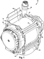
- Figs. 1 to 9 illustrate a seat belt retractor 10, in accordance with an example of the present invention.
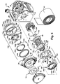
- the seat belt retractor 10 comprises a frame 12, a spool 14 ( Fig. 5 ), a rewind spring 16 ( Fig. 5 ), an inertia locking system 18 ( Fig. 3 ), a pretensioner 20, and a load limiting system 22 ( Fig. 5 ).
- the inertia locking system 18 and the pretensioner 20 are connected to the spool 14 through a torsion bar 150 that is a component of the load limiting system 22.
- the frame 12 is formed of metal or another strong and relatively rigid material.
- the frame 12 includes two side walls 24 and 26, which are laterally spaced apart from one another.
- the side walls 24 and 26 are joined by a base wall 28 to form a U-shaped structure.
- a supplemental frame member 32 Secured to the side wall 26, on a surface 30 of the side wall 26 presented away from the side wall 24, is a supplemental frame member 32, which is also formed of metal or another strong and relatively rigid material.
- An outer peripheral portion 33 of the supplemental frame member 32 contacts the side wall 26.
- a bowl-shaped major portion 34 of the supplemental frame member 32 which is formed in one piece with the outer peripheral portion 33, is spaced away from the side wall 26 and receives other components of the seat belt retractor 10, as will become apparent.
- two cross-braces or brace members 36 extend from one side wall 24 to the other side wall 26 at locations opposite the base wall 28 and are securely attached to both side walls.
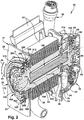
- the spool 14 is mounted in the frame 12 for rotation relative to the frame. As can be seen in Fig. 2 , the spool 14 extends from one side wall 24 of the frame 12 to the other side wall 26 and is spaced apart from the base wall 28. A first end portion 38 of the spool 14 is rotatably supported in or on the side wall 24. A second end portion 40 of the spool 14, which is spaced apart from the first end portion 38 along the length of the spool, is rotatably supported in or on the side wall 26.
- the rotatable support or mounting of the spool 14 in the frame 12 permits a length of seat belt webbing 42 to be wound on and unwound from the spool.
- the spool 14 is rotatable in a webbing withdrawal direction 44 and an opposite webbing retraction direction 46.
- the rewind spring 16 is attached to the first end portion 38 of the spool 14 so as to bias the spool in the webbing retraction direction 46.
- a radially inner end portion 48 of the rewind spring 16 is attached to the first end portion 38 of the spool 14.
- An opposite radially outer end portion 50 of the rewind spring 16 is attached to a housing 52, which is secured by fasteners 54 to the side wall 24 of the frame 12.
- the inertia locking system 18 is disposed adjacent the side wall 26 and supplemental frame member 32 of the frame 12 and adjacent the second end portion 40 of the spool 14.
- the inertia locking system 18 comprises an inertia sensor 60, a lock-up lever 62, an inertia disc 64, a locking pawl 66, and a spool disc 68.
- the inertia sensor 60 ( Fig. 3 ) includes a sensor housing 70, which may be formed of plastic, secured to the supplemental frame member 32.
- a weight support 72 which may also be formed of plastic and which is shaped generally like a cup or bowl.
- the weight support 72 receives an inertia weight 74, which is formed of steel and which is in the shape of a ball.
- a sensor lever 76 which may be formed of plastic, is pivotally mounted at one end on the weight support 72.
- the sensor lever 76 rests on the inertia weight 74.
- Ribs 78 project upwardly, as viewed in Fig. 3 , from a surface of the sensor lever 76 presented away from the inertia weight 74.
- the lock-up lever 62 is pivotally mounted adjacent one end 80 on a pin 82 that projects from the sensor housing 70.
- the opposite end 84 of the lock-up lever 62 rests on the upstanding ribs 78 of the sensor lever 76. Movement of the inertia weight 74 in and relative to the weight support 72 will cause the sensor lever 76 to pivot about its end that is mounted on the weight support. Such pivoting of the sensor lever 76 will cause upward movement of the ribs 78 and consequent upward pivoting of the lock-up lever 62 about the pin 82. Movement of the inertia weight 74 in and relative to the weight support 72 may result from deceleration of a vehicle (not shown) in which the retractor 10 is mounted.
- the inertia disc 64 is connected to the spool 14 through the spool disc 68 and the load limiting system 22, including the torsion bar 150. Under normal circumstances, the inertia disc 64 rotates with the spool 14. The inertia disc 64 can, however, rotate relative to the spool 14 in a vehicle crash condition, as will be explained below.
- Ratchet teeth 88 project radially outward from the outer periphery of the inertia disc 64.
- the ratchet teeth 88 are normally spaced away or apart from the end 84 of the lock-up lever 62. Upon sufficient upward pivoting of the end 84 of the lock-up lever 62, however, the end 84 will come into contact with and engage the ratchet teeth 88.
- the ratchet teeth 88 have faces that are sloped such that the ratchet teeth can pass by the end 84 of the lock-up lever 62 if the inertia disc rotates in the webbing retraction direction 46.
- the engagement of the end 84 of the lock-up lever 62 with the ratchet teeth 88 will, however, prevent the inertia disc 64 from rotating in the webbing withdrawal direction 44.
- the inertia disc 64 is mounted on the spool disc 68 and, more particularly, on a shaft portion 90 of the spool disc, which projects in a direction axially away from the remainder of the spool disc 68.
- the spool disc 68 is mounted on a second end portion 180 of the torsion bar 150.
- splines 165 project radially outwardly from the torsion bar 150 and engage grooves 94 formed in a radially inner surface of the spool disc 68. The spool disc 68 will thus always rotate together with the second end portion 180 of the torsion bar 150.
- the locking pawl 66 is pivotally mounted at one end on the spool disc 68. At the other end of the locking pawl 66 are a plurality of locking teeth 96. The locking teeth 96 are positioned adjacent the radially outer periphery of the spool disc 68. A lock pawl spring 98 biases the locking pawl 66 to pivot in a radially inward direction away from the radially outer periphery of the spool disc 68.
- the spool disc 68 and the inertia disc 64 have interfitting portions 100 and 102, respectively, which are contoured and dimensioned such that the interfitting portion 100 of the spool disc 68 fits into the interfitting portion 102 of the inertia disc when the inertia disc is mounted on the shaft portion 90 of the spool disc.
- the interfitting portion 102 of the inertia disc 64 generally resembles a sector of a circle.
- the interfitting portion 100 of the spool disc 68 also generally resembles a sector of a circle, but with a smaller central angle and a shorter arc than the interfitting portion 102.
- the interfitting portion 100 thus is able to move through a limited range of rotational movement relative to the interfitting portion 102.
- the interfitting portion 100 of the spool disc 68 is positioned relative to the interfitting portion 102 of the inertia disc 64 in the orientations shown in Fig. 3 . This relative positioning of the interfitting portions 100 and 102 is maintained during normal rotation of the spool disc 68 and the inertia disc 64 with the spool 14.
- the inertia disc spring 104 when subjected to the pressure of the locking pawl 66, will tend to be compressed and will resist such compression with a spring force that will urge the locking pawl to pivot relative to the spool disc 68 so that the locking teeth 96 of the locking pawl move outward of the radially outer periphery of the spool disc.
- the locking teeth 96 Upon sufficient outward movement, the locking teeth 96 will engage frame teeth 106 that project radially inward about a central opening 108 in the supplemental frame member 32. Almost immediately after the locking teeth 96 engage the frame teeth 106, the interfitting portion 100 of the spool disc 68 will reach the end of its possible movement or travel in a counter-clockwise direction, as viewed in Fig. 3 , relative to the interfitting portion 102 of the inertia disc 64, and rotational movement of the spool disc 68 and the inertia disc 64 in the webbing withdrawal direction 44 will be blocked.
- the effect on the spool 14 will depend on the event that caused the foregoing rotational movement to be blocked. If, for example, the vehicle (not shown) in which the retractor 10 is mounted is involved in a low speed collision that results in forward movement of a vehicle occupant and consequent loading of the seat belt webbing 42, or if a vehicle occupant simply moves too quickly and thereby applies a load on the seat belt webbing, neither the pretensioner 20 nor the load limiting system 22 will be actuated.
- Rotational movement of the spool 14 in the webbing withdrawal direction 44 will be blocked due to the connection, which is described below, between the torsion bar 150 and the spool. If, on the other hand, the vehicle (not shown) in which the retractor 10 is mounted is involved in a higher speed collision in which loads on the vehicle and/or a vehicle occupant exceed one or more predetermined thresholds, the pretensioner 20 and/or the load limiting system 22 will be actuated, and rotational movement of the spool 14 will be affected as described below.
- the pretensioner 20 If the loads on the vehicle and/or a vehicle occupant exceed or are anticipated to exceed one or more predetermined thresholds, the pretensioner 20 will be actuated.
- the pretensioner 20 operates to remove slack from the seat belt webbing 42 wound on the spool 14 and also to pull the seat belt webbing close to and against a vehicle occupant (not shown).
- Actuation of the pretensioner 20 may be in response to a signal from a crash sensor (not shown), such as an accelerometer, mounted on a forward part of a vehicle (not shown) indicating a vehicle crash condition, a signal from a forward-looking radar unit or camera (not shown) mounted in a vehicle indicating an impending and likely unavoidable vehicle crash condition, a load applied to the seat belt webbing by the body of a vehicle occupant, or any other suitable indicator of an actual or anticipated vehicle crash condition.
- a crash sensor such as an accelerometer, mounted on a forward part of a vehicle (not shown) indicating a vehicle crash condition
- a signal from a forward-looking radar unit or camera mounted in a vehicle indicating an impending and likely unavoidable vehicle crash condition
- a load applied to the seat belt webbing by the body of a vehicle occupant or any other suitable indicator of an actual or anticipated vehicle crash condition.
- the pretensioner 20 may have any one of many different designs and constructions that are commercially available. As shown in Fig. 4 , however, the pretensioner 20 is an assembly that comprises a vaned turbine wheel 110, a tube 112, a micro gas generator 114, and an elongated flexible member or snake 116 received in the tube.
- the turbine wheel 110 is formed of a metal, such as steel, or another strong, relatively rigid material.
- the turbine wheel 110 is either formed in one piece with or fixed or immovably connected to the spool disc 68 so that the turbine wheel and the spool disc rotate together. As shown in Fig.
- the turbine wheel 110 includes a plurality of radially outwardly projecting turbine blades or vanes 120 arrayed around the radially outer periphery of a hub portion 122 of the turbine wheel. Adjacent to and along one side of each of the vanes 120 is a radially outwardly projecting rim 124 that has a greater radial extent than the vanes. Grooves 126 are formed in a radially inner surface of the hub portion 122 of the turbine wheel 110 and receive splines 128 formed on a radial outer surface of the spool disc 68. The turbine wheel 110 will thus always rotate together with the spool disc 68, which, in turn, always rotates together with the second end portion 180 of the torsion bar 150.
- the tube 112 is formed of a metal, such as steel, or another material capable of withstanding high gas pressures.
- the tube 112 has a first end portion 130 located adjacent the vanes 120 of the turbine wheel 110 and the supplemental frame member 32 and spaced away from the base wall 28 of the frame 12.
- the tube 112 has an opposite second end portion 132 located adjacent the base wall 28 of the frame 12 and the supplemental frame member 32 and spaced apart from the first end portion 130 across the diameter of the turbine wheel 110.
- Mounted in the second end portion 132 of the tube 112 is the micro gas generator 114.
- the elongated flexible member or snake 116 has one end 134 located in the first end portion 130 of the tube 112 and an opposite second end 136 located near to, but spaced away from the second end portion 132 of the tube 112 and the micro gas generator 114.
- the snake 116 is formed of a material that is flexible, resists being compressed, and can be dug into by the blades or vanes 120 of the turbine wheel 110.
- One such material is nylon 6.
- the elongated flexible member or snake 116 may be one continuous piece of material or several separate pieces arranged in end-to-end abutting relationship.
- the snake 116 has an outer diameter dimensioned to fit closely within the tube 112 to help reduce the possibility of gas generated by the micro gas generator 114 passing along the tube between the inner surface of the tube and the snake.
- An optional supplemental plug or sealing element 138 may be positioned at the second end 136 of the snake 116 between the micro gas generator 114 and the snake to help further prevent gas from passing along passing along the tube 112 between the inner surface of the tube and the snake.
- the tube 112 may have any outer shape or configuration as may required, for example, to facilitate packaging the retractor 10 in a particular vehicle (not shown), provided that the elongated flexible member or snake 116 can follow the shape or configuration to move through the tube from adjacent the second end potion 132 to the first end portion 130.
- an electrical signal is sent to the micro gas generator 114.
- the signal causes the micro gas generator 114 to ignite and to produce or generate gas under pressure.
- the gas from the micro gas generator 114 pushes on the adjacent second end 136 of the elongated flexible member or snake 116, either directly or through the supplemental plug or sealing element 138.
- the elongated flexible member or snake 116 travels lengthwise along the tube 112 and out of the first end portion 130 of the tube, where the snake contacts one of the vanes 120 of the turbine wheel 110.
- the elongated flexible member or snake 116 pushes the vane 120 on the turbine wheel 110, which causes the turbine wheel to rotate in the webbing retraction direction 46.
- the next vane 120 on the turbine wheel contacts the elongated flexible member or snake 116, digs into the outer surface of the elongated flexible member or snake, and is pushed along by the snake, which causes further rotation of the turbine wheel in the webbing retraction direction 46.
- Rotation of the turbine wheel 110 is transmitted to the spool 14 via the spool disc 68, the second end portion 180 of the torsion bar 150, and the remainder of the load limiting system 22 and thereby causes the spool 14 to rotate in the webbing retraction direction 46 to wind up the seat belt webbing 42 on the spool.
- the winding rotation of the spool 14 effectively reduces or eliminates slack in the seat belt webbing 42 wound on the spool and also pulls the seat belt webbing closely and tightly against a vehicle occupant (not shown).
- the snake As the elongated flexible member or snake 116 moves with the turbine wheel 110, the snake is no longer constrained by the tube 112 but is nonetheless contained by the rim 124 of the turbine wheel 110 and the bowl-shaped major portion 34 of the supplemental frame member 32.
- the end 134 and the adjacent portion of the snake pass out of contact with the vanes 120 and are pushed into a curved recess 140 formed in a plastic holder 142 that fits inside the bowl-shaped major portion 34 of the supplemental frame member 32.
- the load limiting system 22 comprises the torsion bar 150 and a stop assembly 152 that limits twisting of the torsion bar and that consequently limits rotation of the spool 14 while the torsion bar is being twisted.
- the stop assembly 152 comprises a hub member 154, an inertia member 156 releasably connected to the hub member, actuation pawls 158a and 158b pivotally mounted on the hub member, leaf springs 160a and 160b resiliently biasing the actuation pawls 158a and 158b in a radially outward direction relative to the hub member, first and second count rings 162 and 163, a count actuation member 164, and a locking mechanism 166.
- the torsion bar 150 is coaxial with the spool 14 and extends lengthwise in an axially extending bore 170 formed in and along a centerline or central longitudinal axis 172 of the spool. More specifically, the bore 170 extends longitudinally within the spool 14 and entirely through the second end portion 40 of the spool 14, terminating in an open end 174 at an end surface of the spool. The bore 170 does not, however, extend entirely through the first end portion 38 of the spool 14, but rather terminates in a closed end 176 adjacent the first end portion 38 of the spool and at about the point where the spool passes through the side wall 24 of the frame 12.
- the torsion bar 150 is an elongated, generally cylindrical member with an enlarged first end portion 178 and an enlarged second end portion 180.
- the first end portion 178 includes outwardly extending splines 182 that engage grooves (not shown) formed adjacent the closed end 176 of the bore 170 in a surface 184 of the spool 14 that defines the bore.
- the second end portion 180 of the torsion bar 150 projects beyond the open end 174 of the bore 170 and the side wall 26 of the frame 12.
- the second end portion 180 of the torsion bar 150 includes outwardly extending splines 165 that engage grooves 94 formed in a radially inner surface of the spool disc 68. Because of the engagement between the splines 182 of the torsion bar 150 and the grooves (not shown) in the surface 184 of the spool 14 and because of the engagement of the splines 165 of the torsion bar and the grooves 94 of the spool disc 68, the spool disc will rotate with the spool unless the torsion bar is being twisted.
- the turbine wheel 110 and the inertia disc 64, both of which are mounted on and connected with the spool disc 68, will likewise rotate with the spool 14.
- the torsion bar 150 is formed of a material that will maintain an unflexed condition throughout a predetermined range of torque loads applied to the torsion bar. If a torque load exceeding a predetermined torque threshold is applied to the torsion bar 150, however, the torsion bar will begin to twist.
- the seat belt webbing 42 may apply a torque load exceeding the predetermined torque threshold to the torsion bar through the spool 14 and the first end portion 178 of the torsion bar.
- the torsion bar 150 With the torque load exceeding the predetermined torque threshold being applied to the torsion bar 150, the torsion bar will begin to twist, with the first end portion 178 rotating relative to the second end portion 180, thereby permitting the spool 14 to rotate with the first end portion 178 in the webbing withdrawal direction 44 and also permitting the seat belt webbing 42 to unwind or pay out from the spool.
- the stop assembly 152 of the load limiting system 22 are configured and dimensioned to permit the foregoing objectives to be achieved by limiting the extent to which the torsion bar 150 is able to twist.
- the stop assembly 152 when actuated, permits a predetermined amount of relative rotation between the first end portion 178 of the torsion bar 150 and the second end portion 180.
- the stop assembly 152 will permit a predetermined amount of relative rotation between the spool 14, together with the first end portion 178 of the torsion bar 150, which is connected to the spool, and the frame 12.
- the stop assembly 152 limits the foregoing relative rotation by being connected to the first end portion 38 of the spool 14 and to the side wall 24 of the frame 12.
- the spool 14 extends between the side walls 24 and 26 of the frame 12.
- the spool 14 is generally cylindrical in shape and generally symmetrical about its central longitudinal axis 172.
- the first end portion 38 of the spool 14 is spaced apart from the second end portion 40 of the spool by a cylindrical belt-receiving portion 190 of the spool on which the seat belt webbing 42 is wound.
- the second end portion 40 of the spool 14 has a larger outer diameter than the belt-receiving portion 190 to help retain the seat belt webbing 42 on the belt-receiving portion.
- the belt-receiving portion 190 of the spool 14 and the first end portion 38 of the spool is an outwardly projecting annular flange portion 192 of the spool that also helps retain the seat belt webbing 42 on the belt-receiving portion.
- the seat belt webbing 42 is thus wound on the belt-receiving portion 190 of the spool 14 between the flange portion 192 and the second end portion 40 of the spool.
- the flange portion 192 of the spool 14 is located between the side walls 24 and 26 of the frame 12, but is closely adjacent the side wall 24.
- the first end portion 38 of the spool 14 extends through the side wall 24 of the frame 12.
- the first end portion 38 of the spool 14 has a large diameter outer circumferential surface 194 adjacent the flange portion 192 of the spool 14 and a smaller diameter outer circumferential surface 196 that is spaced apart from the flange portion 192 by the length of the large diameter outer circumferential surface 194.
- a slot 197 is formed in the smaller diameter outer circumferential surface 196, which receives the radially inner end portion 48 of the rewind spring 16.
- the stop assembly 152 is mounted around the large diameter outer circumferential surface 194. More specifically, the annular locking mechanism 166, which has a central opening 167, surrounds the large diameter outer circumferential surface 194 adjacent the side wall 24 of the spool.
- the count actuation member 164 which is annular or ring-like in shape, is disposed around the large diameter outer circumferential surface 194 at a location axially farther away from the side wall 24 than the second count ring 163 and radially within the first count ring 162.
- the hub member 154 and the inertia member 156 which are also annular or ring-like in shape, are smaller in diameter than the count actuation member 164 and fit radially within the count actuation member.
- rectangular notches 198 are formed in the large diameter outer circumferential surface 194 of the spool adjacent the smaller diameter outer circumferential surface 196.
- Two of the notches 198 which are diametrically opposite one another, receive two rectangular tabs 200 ( Fig. 6 ) that project radially inward at diametrically opposed locations from an inner circumferential surface 202 of the hub member 154 and that fit closely within the notches.
- the remaining two notches 198 which are also diametrically opposite one another, are formed with radially outwardly projecting tabs 199.
- These two notches 198 receive two resilient spring fingers 201 (only one of which is shown in Fig.
- the hub member 154 is thus fixed or attached to the first end portion 38 of the spool 14 so as to rotate with the first end portion and also so as to be held against axial movement or movement along the central longitudinal axis 172 relative to the first end portion of the spool.
- the inner circumferential surface 202 of the hub member 154 is an inner circumferential surface of a wall 206, which extends axially or along the central longitudinal axis 172.
- a rim 204 On the outer circumference of the wall 206 and the hub member 154 is a rim 204, which projects outward or radially relative to the central longitudinal axis 172.
- the outwardly projecting rim 204 and the axially extending wall 206 of the hub member 154 form features that permit the actuation pawls 158a and 158b and the leaf springs 160a and 160b to be mounted on the hub member 154, as will be described below.
- the rim 204 and the wall 206 also form features that engage features on the inertia member 156 to connect or engage the hub member 154 to or with the inertia member 156, as will also be described below.
- actuation pawls 158a and 158b To help mount the actuation pawls 158a and 158b on the hub member 154, two mounting holes 208a, b (only one of which is shown in Fig. 6 ) are formed in the rim 204 at diametrically opposite positions. Adjacent to each of the mounting holes 208a, b, a socket 210a, b and a fan-shaped tab slot 212a, b are formed in the axially extending wall 206. Each of the actuation pawls 158a and 158b has an enlarged cylindrical shoulder 214a, b at one end and contoured tip 216a, b at its opposite end.
- a post 218a, b projects from each shoulder 214a, b in a direction approximately perpendicular to the length of each actuation pawl 158a, b.
- a fan-shaped tab 219a, b projects from each shoulder 214a, b in a radial direction.
- the actuation pawl In order to mount each actuation pawl 158a, b on the hub member 154, the actuation pawl is positioned relative to the hub member such that the shoulder 214a, b is aligned with its corresponding socket 210a, b, the post 218a, b is aligned with its corresponding mounting hole 208a, b, and the fan-shaped tab 219a, b is aligned with the corresponding fan-shaped tab slot 212a, b.
- each shoulder 214a, b into its corresponding socket 210a, b, each post 218a, b into its corresponding mounting hole 208a, b, and each fan-shaped tab 219a, b into its corresponding fan-shaped tab slot 212a, b mounts each actuation pawl 158a, b on the hub member 154. Subsequently pivoting the each actuation pawl 158a, b relative to the hub member 154 causes the fan-shaped tabs 219a, b to move into slots (not shown) in the hub member so that the actuation pawl is held in place on the hub member against axial movement or movement along the central longitudinal axis 172.
- each of the leaf springs 160a and 160b has a U-shaped hook 220a, b at one end and a contoured tip 222a, b at its opposite end. Adjacent each U-shaped hook 220a, b is a short, flexible mounting finger 224a, b that is spaced axially from and projects at a small angle radially outward from the remainder of each leaf spring 160a, b.
- each leaf spring 160a, b is positioned relative to the hub member such that the U-shaped hook 220a, b is aligned with its corresponding spring socket 226a, b. Moving each U-shaped hook 220a, b into its corresponding spring socket 226a, b mounts each leaf spring 160a, b on the hub member 154. At the same time, each mounting finger 224a, b is moved under a corresponding clip 228a, b that projects axially from the rim 204 so that the leaf spring is held in place on the hub member 154 against axial movement or movement along the central longitudinal axis 172.
- the contoured tips 222a, b of the leaf springs engage and resiliently press against the actuation pawls 158a, b so that their respective contoured tips 216a, b are biased in outward directions or radially relative to the central longitudinal axis 172.
- features that engage features on the inertia member 156 to connect or engage the hub member 154 to or with the inertia member 156 are features that engage features on the inertia member 156 to connect or engage the hub member 154 to or with the inertia member 156.
- two slotted guides 230a, b are formed at diametrically opposite positions in the wall 206.
- two latch members 232a, b project axially away from the rim 204 at diametrically opposite positions.
- Each ramp 234a, b has a moderately sloped surface 236a, b, an opposed sharply sloped surface 238a, b, and a flat radially innermost surface 237a, b, which is interposed between the moderately sloped surface and the sharply sloped surface.
- the inertia member 156 includes a wall 240 that extends axially or along the central longitudinal axis 172.
- the wall 240 has two different heights or axial extents. A first, radially outer, greater height or axial extent terminates in an end surface 242. A second, radially inner, lesser height or axial extent terminates in an end surface 244, which effectively provides a step or ledge adjacent an inner circumference of the wall 240.
- Two gaps or windows 246a, b are formed in the wall 240 at diametrically opposite locations around the circumference of the inertia member 156.
- each of the hooks 248a, b Adjacent each of the hooks 248a, b are two tabs 252a, b and 254a, b, which also project from the radially inner circumferential surface 250 of the wall 240 in an inward direction or radially inward relative to the central longitudinal axis 172.
- Each tab 252a, b is located between its corresponding hook 248a, b and its corresponding tab 254a, b.
- Each tab 252a, b is also spaced apart around the radially inner circumferential surface 250 from its corresponding tab 254a, b.
- Each tab 254a, b has an axially extending wedge member 258a, b.
- the wall 240 of the inertia member 156 has an inner diameter that is larger than the outer diameters of the rim 204 and the wall 206 of the hub member 154.
- the inertia member 156 may thus be positioned so as to surround the hub member 154. To so position the inertia member 156 relative to the hub member 154, however, the radially inwardly projecting hooks 248a, b and tabs 252a, b and 254a, b must be positioned to as to interfit with the slotted guides 230a, b and the ramps 234a, b.
- the tabs 252a, b and 254a, b must be positioned on opposite sides of the slotted guides 230a, b so that the slotted guide 230a is disposed between the tabs 252a and 254a and the slotted guide 230b is disposed between the tabs 252b and 254b.
- the hook 248a is positioned between the slotted guide 230a and the ramp 234a
- the hook 248b is positioned between the slotted guide 230b and the ramp 234b.
- the wall 240 of the inertia member is also positioned relative to the actuation pawls 158a, b such that the wall blocks or prevents the actuation pawls from pivoting in a radially outward direction under the bias of the leaf springs 160a, b.
- the latch members 232a, b snap over the wall 240 at its radially inner, lesser height or axial extent so as to engage the end surface 244.
- the inertia member 156 normally moves or rotates together with the hub member 154, and thus with the spool 14, the inertia member may move or rotate relative to the hub member.
- the pretensioner 20 is actuated, the spool 14 will be abruptly moved or rotated or accelerated in the webbing retraction direction 46. If the spool 14 is abruptly moved or rotated or accelerated in the webbing retraction direction 46, the inertia member 156 will tend to lag the rotational movement of the hub member 154 and thus will rotate relative to the hub member.
- each hook 248a, b of the inertia member will travel along the moderately sloped surface 236a, b of the corresponding ramp 234a, b of the hub member, across the flat radially innermost surface 237a, b of the ramp, and down over the opposed sharply sloped surface 238a, b of the ramp.
- each tab 254a, b of the inertia member 156 will move into the slot 231a, b of the corresponding slotted guide 230a, b and travel along the slot until the wedge member 258a, b of the tab 254a, b is wedged or frictionally engaged with the slotted guide.
- the limited amount of relative rotation that has been permitted between the hub member 154 and the inertial member 156 is sufficient to cause the windows 246a, b in the wall 240 of the inertia member to rotate into alignment with the tips 216a, b of the actuation pawls 158a, b mounted on the hub member, as can be seen in Fig. 8 .
- the leaf springs 160a, b are then able to bias the tips 216a, b of the actuation pawls 158a, b radially outward through the windows 246a, b into engagement with the count actuation member 164.
- the count actuation member 164 includes a wall 260, which extends axially or along the central longitudinal axis 172, and a rim 262, which projects outward or radially relative to wall 260 and the central longitudinal axis 172.
- a radially inner circumferential surface 264 of the wall 260 and the count actuation member 164 are a plurality of teeth 266, which project radially inward in an array arranged around the entire circumference of the inner circumferential surface 264.
- Each tooth 266 includes a moderately sloped surface 268, an opposed sharply sloped surface 270, and a flat radially innermost surface 272, which is interposed between the moderately sloped surface and the sharply sloped surface.
- the tips 216a, b of the actuation pawls 158a, b are able to move along the moderately sloped surfaces 268 of the teeth 266 of the count actuation member 164 and also along the flat radially innermost surfaces 272 of the teeth in the webbing retraction direction 46 so the spool 14 and the hub member 154 are free to rotate relative to the count actuation member 164 in the webbing retraction direction 46.
- the hub member 154, the inertia member 156, the actuation pawls 158a, b, and the leaf springs 160a, b comprise an actuation mechanism for actuating the counting process and a counting mechanism that comprises the count actuation member 164, the first and second count rings 162 and 163, and the locking mechanism 166.
- the outwardly projecting rim 262 contacts or engages a corresponding annular surface (not shown) on the interior of the housing 52.
- the contact or engagement between the rim 262 and the annular surface (not shown) of the housing 52 will hold the count actuation member 164 against axial movement or movement along the central longitudinal axis 172 in a direction away from the frame 12 because the housing 52 is secured by the fasteners 54 to the side wall 24 of the frame 12.
- the count actuation member 164 is held against axial movement or movement along the central longitudinal axis 172 in a direction toward the frame 12 by engagement with other elements of the retractor 10, as will be explained below.
- Optional tabs 274 may be formed on the outer circumference of the wall 260 adjacent the rim 262 to engage corresponding slots or notches (not shown) in the housing 52 to help position the count actuation member 164 in a desired rotational orientation.
- the tabs 274 are frangible so that they will break away from the count actuation member 164 when the count actuation member begins to rotate.
- the first count ring 162 Projecting from the outer circumference of the wall 260 adjacent the rim 262 on a side of the rim presented way from the housing 52 is a count actuation tab 276, which is shown in Fig. 6 out of its ordinary rotational position relative to the first and second count rings 162 and 163, in particular, for purposes of illustration only.
- the count actuation tab 276 is positioned to engage the first count ring 162.
- the first count ring 162 includes a wall 280, which extends axially or along the central longitudinal axis 172, and a rim 282, which projects outward or radially relative to wall 280 and the central longitudinal axis 172.
- the rim 282 contacts or engages a corresponding annular surface (not shown) on the interior of the housing 52.
- the contact or engagement between the rim 282 and the annular surface (not shown) of the housing 52 will hold the first count ring 162 against axial movement or movement along the central longitudinal axis 172 in a direction away from the frame 12 because the housing 52 is secured by the fasteners 54 to the side wall 24 of the frame 12.
- the first count ring 162 is held against axial movement or movement along the central longitudinal axis 172 in a direction toward the frame 12 by engagement with other elements of the retractor 10, as will be explained below.
- the wall 280 of the first count ring 162 has a radially inner circumferential surface 284. Projecting radially inwardly from the radially inner circumferential surface 284 is a first counting tab 286.
- the first counting tab 286 projects radially inwardly to an extent sufficient to ensure that the count actuation tab 276 of the count actuation member 164 will engage the first counting tab 286.
- the count actuation tab 276 is positioned adjacent the first counting tab 286 on a side of the first counting tab such that the count actuation tab 276 is free to rotate in the webbing withdrawal direction 44 relative to the first counting tab 286 through an arc of approximately 320° before the count actuation tab will contact, strike or engage with the first counting tab 286.
- the count actuation tab 276 contacts, strikes or engages with the first counting tab 286 while rotating in the webbing withdrawal direction 44, the count actuation tab 276 will begin to push, drive or rotate the first counting tab 286 and thus the first count ring 162 in the webbing withdrawal direction 44.
- the first counting tab 286 of the first count ring 162 is positioned to engage the second count ring 163.
- the second count ring 163 includes a wall 288, which extends axially or along the central longitudinal axis 172, an outer rim 290, which projects outward or radially relative to wall 288 and the central longitudinal axis 172, and an inner rim 292, which projects inward or radially relative to wall 288 and the central longitudinal axis 172.
- the outer rim 290 of the second count ring 163 contacts or engages a corresponding annular surface (not shown) on the interior of the housing 52.
- the contact or engagement between the outer rim 290 and the annular surface (not shown) of the housing 52 will hold the second count ring 163 against axial movement or movement along the central longitudinal axis 172 in a direction away from the frame 12 because the housing 52 is secured by the fasteners 54 to the side wall 24 of the frame 12.
- Optional tabs 293 may be formed on a radially outer circumferential surface 294 of the wall 288 adjacent the outer rim 290 to engage corresponding slots or notches (not shown) in the housing 52 to help position the second count ring 163 in a desired rotational orientation.
- the tabs 293 are frangible so that they will break away from the second count ring 163 when the second count ring begins to rotate.
- the outer rim 290 is also in contact with an axially innermost end of the wall 280 of the first count ring 162 and thereby holds the first count ring against axial movement or movement along the central longitudinal axis 172 in a direction toward the frame 12.
- the inner rim 292 of the second count ring 163 is in contact with an axially innermost end of the wall 260 of the count actuation member 164 and thereby holds the count actuation member against axial movement or movement along the central longitudinal axis 172 in a direction toward the frame 12.
- the second count ring 163 is held against axial movement or movement along the central longitudinal axis 172 in a direction toward the frame 12 by engagement with other elements of the retractor 10, as will be explained below.
- a second counting tab 296 projects outwardly or radially relative to the central longitudinal axis 172 from the radially outer circumferential surface 294 of the wall 288.
- the second counting tab 296 projects radially outwardly to an extent sufficient to ensure that the first counting tab 286 of the first count ring 162 will engage the second counting tab 296.
- the first counting tab 286 is positioned adjacent the second counting tab 296 on a side of the second counting tab such that the first counting tab 286 is free to rotate in the webbing withdrawal direction 44 relative to the second counting tab 296 through an arc of approximately 320° before the first counting tab 286 will contact, strike or engage with the second counting tab 296.
- the first counting tab 286 When the first counting tab 286 contacts, strikes or engages with the second counting tab 296 while rotating in the webbing withdrawal direction 44, the first counting tab 286 will begin to push, drive or rotate the second counting tab 296 and thus the second count ring 163 in the webbing withdrawal direction 44.
- the wall 288 of the second count ring 163 also has a radially inner circumferential surface 298. Projecting radially outwardly from the radially inner circumferential surface 298 is a third counting tab 300.
- the third counting tab 300 projects radially inwardly to an extent sufficient to ensure that the third counting tab will engage the locking mechanism 166.
- the locking mechanism 166 includes a cage 302, a locking hub 304, three rollers 306, and three rivets 308.
- the cage 302, which is annular or ring-like in shape, may be formed of a plastic material.
- the cage 302 engages the rollers 306 and the locking hub 304, as will be explained below, and can cause the rollers to move relative to the locking hub.
- the rivets 308 secure the locking hub 304 to the side wall 24 of the frame 12.
- the cage 302 includes a short wall 310, which extends axially or along the central longitudinal axis 172, and a rim 312, which projects outward or radially relative to wall 310 and the central longitudinal axis 172.
- the rim 312 of the cage 302 is in contact with an axially innermost end of the wall 288 of the second count ring 163 and thereby holds the second count ring against axial movement or movement along the central longitudinal axis 172 in a direction toward the frame 12.
- the rim 312 of the cage 302 is in contact with the locking hub 304, which, in turn, is in contact with the side wall 24 of the frame 12 and thereby holds the count actuation member against axial movement or movement along the central longitudinal axis 172 in a direction toward the frame.
- the wall 310 of the cage 302 has a radially outer circumferential surface 314. Projecting radially outwardly from the radially outer circumferential surface 314 is a lock actuation tab 316.
- the lock actuation tab 316 projects radially outwardly to an extent sufficient to ensure that the third counting tab 300 of the second count ring 163 will engage the lock actuation tab 316.
- the third counting tab 300 is positioned adjacent the lock actuation tab 316 on a side of the lock actuation tab such that the third counting tab 300 is free to rotate in the webbing withdrawal direction 44 relative to the lock actuation tab 316 through an arc of approximately 260° before the third counting tab 300 will contact, strike or engage with the lock actuation tab 316.
- the third counting tab 300 contacts, strikes or engages with the lock actuation tab 316 while rotating in the webbing withdrawal direction 44, the third counting tab 300 will begin to push, drive or rotate the lock actuation tab 316 and thus the cage 302 in the webbing withdrawal direction 44.
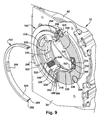
- the wall 310 of the cage 302 also has a radially inner circumferential surface 318. Projecting axially from the wall 310 as extensions of the radially inner circumferential surface 318 are three, circumferentially spaced apart pushing posts 320 and three circumferentially spaced apart positioning posts 322, only two of which is shown in Figs. 5 and 9 .
- the pushing posts 320 and the positioning posts 322 project in a direction toward the side wall 24 of the frame 12.
- Each positioning post 322 is located adjacent a corresponding pushing post 320 and is spaced circumferentially away from the corresponding pushing post 320 by a distance approximately equal to the diameter of each of the rollers 306.
- Each roller 306 is captured between a pushing post 320 and its corresponding positioning post 322.
- each pushing post 320 At the distal end of each pushing post 320 is a small hook or clip 324, only one of which is shown in Figs. 5 and 9 .
- the three clips 324 snap over the edge of the locking hub 304 to secure or attach the cage 302 to the locking hub in an axial direction or along the central longitudinal axis 172. The three clips 324 still permit the cage 302 to move circumferentially or rotate relative to the locking hub 304.
- the pushing posts 320 will push each of the rollers 306 through a short distance or arc in the webbing withdrawal direction.
- the three rollers 306 are cylindrical in shape and have outer circumferential surfaces formed with axially extending splines or ribs 328. In addition to being captured between the pushing posts 320 and the positioning posts 322 of the cage 302, the rollers 306 are retained within the locking hub 304.
- the locking hub 304 is formed of a strong and relatively rigid material, such as steel, and has a central opening 167.
- the locking hub 304 may be formed as a single piece of material or, as shown, may be formed as multiple pieces, such as multiple stamped metal plates that are stacked on one another.
- the surface of the locking hub 304 that defines the central opening 167 includes three spool-engaging surface portions 330 and three ramp surface portions 332, which alternate with the spool-engaging surface portions around the central opening.
- the three spool-engaging surface portions 330 are arcuate in shape and fit closely around the large diameter outer circumferential surface 194 of the first end portion 38 of the spool 14.
- Each of the three ramp surface portions 332 includes a roller resting surface portion 334 and an adjacent roller locking surface portion 336.
- the rollers 306 may be positioned in contact with the roller resting surface portions 334 without also contacting the large diameter outer circumferential surface 194 of the first end portion 38 of the spool 14.
- the cage 302 In normal operation of the retractor 10, the cage 302 is positioned relative to the locking hub 304 such that the rollers 306 are positioned and maintained against the roller resting surface portions 334 and free from contact with the large diameter outer circumferential surface 194 of the first end portion 38 of the spool 14.
- the spool 14 is thus free to rotate relative to the locking mechanism in either the webbing withdrawal direction 44 or the webbing retraction direction 46.
- the third counting tab 300 begins to push, drive or rotate the lock actuation tab 316 and thus the cage 302 in the webbing withdrawal direction 44, however, the pushing posts 320 will push each of the rollers 306 away from its corresponding roller resting surface portion 334 and along the adjacent roller locking surface portion 336.
- Each roller locking surface portion 336 is inclined in a radial direction so as to be closer to the large diameter outer circumferential surface 194 of the first end portion 38 of the spool 14 as the distance from the roller resting surface portion 334 increases.
- the rollers 306 move along the roller locking surfaces portions 336 away from the roller resting surface portions 334, the rollers will be forced into contact with the large diameter outer circumferential surface 194 of the first end portion 38 of the spool 14 and the splines 328 on the rollers will dig into the large diameter outer circumferential surface 194 of the first end portion 38 of the spool 14.
- a vehicle occupant when the retractor 10 is installed in a vehicle (not shown), a vehicle occupant (not shown) will grasp a buckle tongue (not shown) that is attached to the seat belt webbing 42 wound on the spool 14 of the retractor and will pull the buckle tongue and the webbing away from the retractor in order to don the seat belt by drawing the seat belt webbing across the occupant's body and connecting the buckle tongue to a buckle (not shown).
- the webbing unwinds from the spool 14 and rotates the spool in the webbing withdrawal direction 44.
- the load applied to the seat belt webbing 42 by the occupant's body may produce higher speed and higher acceleration withdrawal movements of the seat belt webbing 42 and higher acceleration rotational movements of the spool 14. If such higher acceleration movements of the spool 14 exceed a predetermined low spool acceleration threshold, the spool movements will cause the spool disc 68 to accelerate relative to the inertia disc 64, thereby resulting in rotation of the inertia disc to lag rotation of the spool disc and effectively resulting in relative rotation between the spool disc and the inertia disc.
- the locking teeth 96 of the locking pawl 66 will then pivot into contact with the frame teeth 106 in the supplemental frame member 32 and prevent further rotation of the spool disc 68 and the spool 14 in the webbing withdrawal direction 44.
- rotational movement of the spool in the webbing withdrawal direction 44 will be blocked as described above.
- the inertia weight 74 may move in and relative to the weight support 72, thereby causing the sensor lever 76 to pivot and produce upward pivoting of the lock-up lever 62 into engagement with the ratchet teeth 88 of the inertia disc 64.
- Engagement between the lock-up lever 62 and the ratchet teeth 88 of the inertia disc 64 will prevent the inertia disc 64 from rotating with the spool disc 68 and thereby cause relative rotation between the inertia disc and the spool disc if there is any rotation of the spool 14 in the webbing withdrawal direction 44.
- the locking teeth 96 of the locking pawl 66 will then pivot into contact with the frame teeth 106 in the supplemental frame member 32 and prevent further rotation of the spool disc 68 and the spool 14 in the webbing withdrawal direction 44.
- Such movement of the inertia weight 74 in and relative to the weight support 72 will occur if the vehicle deceleration exceeds a predetermined low vehicle deceleration threshold.
- a predetermined high vehicle deceleration threshold Provided such vehicle deceleration does not exceed a predetermined high vehicle deceleration threshold, and provided also that other conditions do not result in actuation of the pretensioner 20 and the load limiting system 22, rotational movement of the spool in the webbing withdrawal direction 44 will be blocked as described above.
- the pretensioner 20 and the load limiting system 22 may be actuated.
- the pretensioner 20 may be actuated in response to a vehicle sensor (not shown), such as an accelerometer mounted in a forward location in the vehicle, detecting a rapid deceleration of the vehicle, such as a deceleration exceeding the predetermined high vehicle deceleration threshold, indicating the actual occurrence of a serious vehicle crash condition.
- the pretensioner 20 may alternatively or additionally be actuated in response to a vehicle sensor (not shown), such as a forward-looking radar unit or a forward-looking camera, detecting an anticipated and potentially unavoidable serious vehicle crash condition.
- the pretensioner 20 may alternatively or additionally be actuated in response to a vehicle sensor (not shown), such as a camera or a capacitive sensor directed toward or located adjacent to the vehicle occupant, detecting movement of the vehicle occupant indicating the actual occurrence of a serious vehicle crash condition. Any desired system or mechanism may be used to determine whether and when to actuate the pretensioner 20, provided the pretensioner is anticipated to be actuated in sufficient time to assist or help in protecting the vehicle occupant.
- a vehicle sensor not shown
- Any desired system or mechanism may be used to determine whether and when to actuate the pretensioner 20, provided the pretensioner is anticipated to be actuated in sufficient time to assist or help in protecting the vehicle occupant.
- the pretensioner 20 When actuated, the pretensioner 20 operates to remove slack from the seat belt webbing 42 wound on the spool 14 and also to pull the seat belt webbing close to and against a vehicle occupant (not shown). Actuation of the pretensioner 20 starts with actuation of the micro gas generator 114.
- the micro gas generator 114 may be actuated by an electrical signal sent from a sensor or by an electrical signal resulting from an electrical circuit being completed by a sensor. Although the micro gas generator 114 is shown as electrically actuated, the micro gas generator may be mechanically actuated.
- the micro gas generator 114 When actuated, the micro gas generator 114 produces or generates gas, which pushes the elongated flexible member or snake 116 against the vanes 120 of the turbine wheel 110, thereby rotating the turbine wheel 110 in the webbing retraction direction 46.
- Rotation of the turbine wheel 110 is transmitted to the spool 14 via the spool disc 68, the end portion 180 of the torsion bar 150, and the remainder of the load limiting system 22 and thereby causes the spool 14 to rotate in the webbing retraction direction 46 to wind up the seat belt webbing 42 on the spool.
- Such winding rotation of the spool 14 effectively reduces or eliminates slack in the seat belt webbing 42 wound on the spool and also pulls the seat belt webbing closely and tightly against the vehicle occupant (not shown).
- Actuation of the pretensioner 20 actuates the load limiting system 22 by producing abrupt and high acceleration of the spool 14 in the webbing retraction direction 46.
- the high acceleration of the spool 14 in the webbing retraction direction 46 causes relative rotation between the hub member 154 and the inertia member 156. With such relative rotational movement between the hub member 154 and the inertia member 156, the windows 246a, b in the wall 240 of the inertia member to rotate into alignment with the tips 216a, b of the actuation pawls 158a, b mounted on the hub member.
- the leaf springs 160a, b then bias the tips 216a, b of the actuation pawls 158a, b radially outward through the window 246a, b into engagement with the teeth 266 of the count actuation member 164.
- the hub member 154 and the inertia member 156 cannot rotate relative to the count actuation member 164 in the webbing withdrawal direction 44.
- the vehicle (not shown) in which the retractor 10 is mounted is subjected to a serious crash condition during or after actuation of the pretensioner 20, the vehicle occupant (not shown) will move against the seat belt webbing 42, which extends across the body of the vehicle occupant. Such movement of the body of the vehicle occupant, after operation of the pretensioner is completed, will impose a load on the seat belt webbing 42 and cause acceleration of the spool 14 of the retractor 10 in the webbing withdrawal direction 44.
- the stop assembly 152 With such rotation of the first end portion 178 of the torsion bar 150 relative to the second end portion 180 and with the actuation pawls 158a, b engaging the count actuation member 164 due to actuation of the pretensioner 20, the stop assembly 152 will both "count” and limit the number of rotations of the first end portion 178 of the torsion bar 150 relative to the second end portion 180 of the torsion bar and thus limit twisting of the torsion bar. Specifically, rotation of the spool 14 in the webbing withdrawal direction 44 under the foregoing circumstances will cause the hub member 154, the inertia member 156, and the count actuation member 164 to rotate in the webbing withdrawal direction 44.
- Rotation of the count actuation member 164 will produce movement of the count actuation tab 276 through an arc of 320° into contact with the first counting tab 286 on the first count ring 162.
- the count actuation tab 276 will push the first counting tab 286 and the first count ring 162 through an additional arc of 320° into contact with the second counting tab 296 on the second count ring 163.
- the count actuation tab 276 will push the first counting tab 286, the first count ring 162, the second counting tab 296, and the second count ring 163 through an additional arc of 260° until the third counting tab 300 on the second count ring 163 contacts, strikes or engages with the lock actuation tab 316 on the cage 302 of the locking mechanism 166.
- the retractor 10 is described as including two count rings 162 and 163, the retractor may include a greater or lesser number of count rings.
- the retractor 10 may also include no count rings at all.
- the count actuation member 164 and the first count ring 162 are described as being rotatable through arcs of 320° and while the second count ring 163 is described as being rotatable through an arc of 260°, the actuation member 164 and the first and second count rings 162 and 163 may be rotatable through smaller arcs or, potentially, slightly greater arcs.
- Adjusting the arcs through which the actuation member 164 and the first and second count rings 162 and 163 are rotatable may be accomplished by changing the arcuate lengths of the count actuation tab 276 and/or the first, second and/or third counting tabs 286, 296, and 300 (or, in other words, the lengths the count actuation tab 276 and/or the first, second and/or third counting tabs 286, 296, and 300 about the circumferences of the actuation member 164 and the first and second count rings 162 and 163).
- Adjusting the arcs through which the actuation member 164 and the first and second count rings 162 and 163 are rotatable may also or alternatively be accomplished by adjusting the starting positions of the actuation member 164, the first count ring 162, the second count ring 163 and/or the cage 302 and thus the count actuation tab 276, the first counting tab 286, the second counting tab 296, the third counting tab 300, and/or the lock actuation tab 316 relative to one another.
- Actuation of the load limiting system 22 and, more particularly, actuation of relative rotational movement of the count actuation member 164, the first and second count rings 162 and 163, and the locking mechanism 166 is described above as both (a) occurring or being initiated on or upon the circumstance or occasion or occurrence of actuation of the pretensioner and (b) occurring as a result of or being effected or caused by actuation of the pretensioner 20.
- actuation of the load limiting system 22 and, specifically, actuation of relative rotational movement of the count actuation member 164, the first and second count rings 162 and 163, and the locking mechanism 166 is described above as being caused by relative rotation between the hub member 154 and the inertia member 156 resulting from acceleration of the spool 14 by the pretensioner. Nonetheless, the load limiting system 22 might be actuated upon the actuation of the pretensioner 20 without also be actuated by the actuation of the pretensioner.
- the electrical signal that actuates the micro gas generator 114 could also be used to actuate an electromechanical linkage to produce relative movement between the hub member 154 and the inertia member 156, thereby resulting in the load limiting system being actuated by the same input as the pretensioner without also being actuated as a result of actuation of the pretensioner.
- the load limiting system 22 may be actuated by actuation of the pretensioner 20.
- the pretensioner 20 rather than have the pretensioner 20 cause relative rotation between the hub member 154 and the inertia member 156 through high acceleration rotation of the spool 14, movement of the elongated flexible member or snake 116 of the pretension could be used, directly or indirectly, to shift the position of the hub member 154 and/or the inertia member 156 and thereby to allow the actuation pawls 158a, b to engage the count actuation member 164 so as to actuate the load limiting system 22.
Landscapes
- Engineering & Computer Science (AREA)
- Mechanical Engineering (AREA)
- Automotive Seat Belt Assembly (AREA)
Description
- The present invention relates to a seat belt retractor with both pretensioning capability and load limiting capability and, more particularly, to a seat belt retractor with a pretensioner and with load limiting capability that begins with actuation of the pretensioner and ends after a predetermined number of rotations of the retractor spool following actuation of the pretensioner.
- Seat belt retractors typically have a spool on which seat belt webbing is wound and from which webbing may be unwound, for example, when a vehicle occupant extends the seat belt webbing around the occupant's body. In response to a vehicle crash condition, the spool is locked against unwinding so that the seat belt webbing will restrain the vehicle occupant in a vehicle seat. To enhance the performance of seat belt retractors over a range of occupant sizes or weights and over a range of vehicle crash conditions, pretensioners have been added to seat belt retractors. Similarly, torsion bars have been added to seat belt retractors.
-
WO 2015/199050 A1 describes a seat belt retractor comprising a rotatable spool on which seat belt webbing is wound, the spool being rotatable in a webbing withdrawal direction and an opposite webbing retraction direction; together with a pretensioner actuatable to rotate the spool in the webbing retraction direction; and with a load-limiting system to limit a load applied to a vehicle occupant by the seat belt webbing. The load-limiting system includes a torsion bar mounted such that the torsion bar is twisted when a load in excess of a predetermined load is applied to the spool in the webbing withdrawal direction by the seat belt webbing. A stop assembly is actuatable to limit rotation of the spool in the webbing withdrawal direction to a predetermined number of rotations while the torsion bar is being twisted, the stop assembly being actuated upon actuation of the pretensioner. - The present invention is directed to a seat belt retractor with both pretensioning capability and load limiting capability and, more particularly, to a seat belt retractor with a pretensioner and with load limiting capability that begins with actuation of the pretensioner and ends after a predetermined number of rotations of the retractor spool following actuation of the pretensioner.
- In accordance with an embodiment of the present invention, a seat belt retractor comprises a rotatable spool on which seat belt webbing is wound. The spool is rotatable in a webbing withdrawal direction and an opposite webbing retraction direction. The seat belt retractor also comprises a pretensioner actuatable to rotate the spool in the webbing retraction direction and a load-limiting system to limit a load applied to a vehicle occupant by the seat belt webbing. The load-limiting system includes a torsion bar mounted such that the torsion bar is twisted when a load in excess of a predetermined load is applied to the spool in the webbing withdrawal direction by the seat belt webbing. The load-limiting system also includes a stop assembly actuatable to limit rotation of the spool in the webbing withdrawal direction to a predetermined number of rotations while the torsion bar is being twisted. The stop assembly is actuated upon actuation of the pretensioner.
- The foregoing and other features and advantages of the present invention will become apparent to one skilled in the art upon consideration of the following description of the invention and the accompanying drawings, in which:
-
Fig. 1 is a perspective view of a seat belt retractor in accordance with an embodiment of the present invention; -
Fig. 2 is a sectional view of the seat belt retractor ofFig. 1 ; -
Fig. 3 is an exploded view of one side of the seat belt retractor ofFig. 1 ; -
Fig. 4 is a sectional view through the side of the seat belt retractor shown inFig. 3 ; -
Fig. 5 is an exploded view of the opposite side of the seat belt retractor ofFig. 1 ; -
Fig. 6 is an enlarged view of certain components shown inFig. 5 ; -
Fig. 7 is a view of certain components ofFig. 5 in a first relative orientation; -
Fig. 8 is a view of the components ofFig. 7 in a second relative orientation; and -
Fig. 9 is a sectional view through the side of the seat belt retractor shown inFig. 5 . -
Figs. 1 to 9 illustrate aseat belt retractor 10, in accordance with an example of the present invention. Theseat belt retractor 10 comprises aframe 12, a spool 14 (Fig. 5 ), a rewind spring 16 (Fig. 5 ), an inertia locking system 18 (Fig. 3 ), apretensioner 20, and a load limiting system 22 (Fig. 5 ). As will be explained in greater detail below, theinertia locking system 18 and thepretensioner 20 are connected to thespool 14 through atorsion bar 150 that is a component of theload limiting system 22. - The
frame 12 is formed of metal or another strong and relatively rigid material. Theframe 12 includes twoside walls side walls base wall 28 to form a U-shaped structure. Secured to theside wall 26, on asurface 30 of theside wall 26 presented away from theside wall 24, is asupplemental frame member 32, which is also formed of metal or another strong and relatively rigid material. An outerperipheral portion 33 of thesupplemental frame member 32 contacts theside wall 26. A bowl-shapedmajor portion 34 of thesupplemental frame member 32, which is formed in one piece with the outerperipheral portion 33, is spaced away from theside wall 26 and receives other components of theseat belt retractor 10, as will become apparent. To help ensure that theframe 12 maintains its intended shape during a crash condition of a vehicle (not shown) in which theretractor 10 is installed or mounted, two cross-braces orbrace members 36 extend from oneside wall 24 to theother side wall 26 at locations opposite thebase wall 28 and are securely attached to both side walls. - The
spool 14 is mounted in theframe 12 for rotation relative to the frame. As can be seen inFig. 2 , thespool 14 extends from oneside wall 24 of theframe 12 to theother side wall 26 and is spaced apart from thebase wall 28. Afirst end portion 38 of thespool 14 is rotatably supported in or on theside wall 24. Asecond end portion 40 of thespool 14, which is spaced apart from thefirst end portion 38 along the length of the spool, is rotatably supported in or on theside wall 26. The rotatable support or mounting of thespool 14 in theframe 12 permits a length ofseat belt webbing 42 to be wound on and unwound from the spool. More particularly, thespool 14 is rotatable in awebbing withdrawal direction 44 and an oppositewebbing retraction direction 46. Therewind spring 16 is attached to thefirst end portion 38 of thespool 14 so as to bias the spool in thewebbing retraction direction 46. Specifically, a radiallyinner end portion 48 of therewind spring 16 is attached to thefirst end portion 38 of thespool 14. An opposite radiallyouter end portion 50 of therewind spring 16 is attached to ahousing 52, which is secured byfasteners 54 to theside wall 24 of theframe 12. - The
inertia locking system 18 is disposed adjacent theside wall 26 andsupplemental frame member 32 of theframe 12 and adjacent thesecond end portion 40 of thespool 14. Theinertia locking system 18 comprises aninertia sensor 60, a lock-up lever 62, aninertia disc 64, alocking pawl 66, and aspool disc 68. - The inertia sensor 60 (
Fig. 3 ) includes asensor housing 70, which may be formed of plastic, secured to thesupplemental frame member 32. Mounted on thesensor housing 70 is aweight support 72, which may also be formed of plastic and which is shaped generally like a cup or bowl. Theweight support 72 receives aninertia weight 74, which is formed of steel and which is in the shape of a ball. Asensor lever 76, which may be formed of plastic, is pivotally mounted at one end on theweight support 72. Thesensor lever 76 rests on theinertia weight 74.Ribs 78 project upwardly, as viewed inFig. 3 , from a surface of thesensor lever 76 presented away from theinertia weight 74. The lock-up lever 62 is pivotally mounted adjacent oneend 80 on apin 82 that projects from thesensor housing 70. Theopposite end 84 of the lock-up lever 62 rests on theupstanding ribs 78 of thesensor lever 76. Movement of theinertia weight 74 in and relative to theweight support 72 will cause thesensor lever 76 to pivot about its end that is mounted on the weight support. Such pivoting of thesensor lever 76 will cause upward movement of theribs 78 and consequent upward pivoting of the lock-up lever 62 about thepin 82. Movement of theinertia weight 74 in and relative to theweight support 72 may result from deceleration of a vehicle (not shown) in which theretractor 10 is mounted. - The
inertia disc 64 is connected to thespool 14 through thespool disc 68 and theload limiting system 22, including thetorsion bar 150. Under normal circumstances, theinertia disc 64 rotates with thespool 14. Theinertia disc 64 can, however, rotate relative to thespool 14 in a vehicle crash condition, as will be explained below. Ratchetteeth 88 project radially outward from the outer periphery of theinertia disc 64. Theratchet teeth 88 are normally spaced away or apart from theend 84 of the lock-uplever 62. Upon sufficient upward pivoting of theend 84 of the lock-uplever 62, however, theend 84 will come into contact with and engage theratchet teeth 88. Theratchet teeth 88 have faces that are sloped such that the ratchet teeth can pass by theend 84 of the lock-uplever 62 if the inertia disc rotates in thewebbing retraction direction 46. The engagement of theend 84 of the lock-uplever 62 with theratchet teeth 88 will, however, prevent theinertia disc 64 from rotating in thewebbing withdrawal direction 44. - As can be seen in
Fig. 2 , theinertia disc 64 is mounted on thespool disc 68 and, more particularly, on ashaft portion 90 of the spool disc, which projects in a direction axially away from the remainder of thespool disc 68. Thespool disc 68 is mounted on asecond end portion 180 of thetorsion bar 150. As can be seen inFig. 4 ,splines 165 project radially outwardly from thetorsion bar 150 and engagegrooves 94 formed in a radially inner surface of thespool disc 68. Thespool disc 68 will thus always rotate together with thesecond end portion 180 of thetorsion bar 150. - The locking
pawl 66 is pivotally mounted at one end on thespool disc 68. At the other end of the lockingpawl 66 are a plurality of lockingteeth 96. The lockingteeth 96 are positioned adjacent the radially outer periphery of thespool disc 68. Alock pawl spring 98 biases the lockingpawl 66 to pivot in a radially inward direction away from the radially outer periphery of thespool disc 68. - The
spool disc 68 and theinertia disc 64 have interfittingportions interfitting portion 100 of thespool disc 68 fits into theinterfitting portion 102 of the inertia disc when the inertia disc is mounted on theshaft portion 90 of the spool disc. Theinterfitting portion 102 of theinertia disc 64 generally resembles a sector of a circle. Theinterfitting portion 100 of thespool disc 68 also generally resembles a sector of a circle, but with a smaller central angle and a shorter arc than theinterfitting portion 102. Theinterfitting portion 100 thus is able to move through a limited range of rotational movement relative to theinterfitting portion 102. - In normal operation of the
retractor 10, theinterfitting portion 100 of thespool disc 68 is positioned relative to theinterfitting portion 102 of theinertia disc 64 in the orientations shown inFig. 3 . This relative positioning of theinterfitting portions spool disc 68 and theinertia disc 64 with thespool 14. If, however, rotation of theinertia disc 64 is restrained by, for example, the lock-uplever 62 or if thespool disc 68 is accelerated relative to the inertia disc by, for example, rapid withdrawal of theseat belt webbing 42 and consequent acceleration of thespool 14, theinterfitting portion 100 of the spool disc will tend to move in a counter-clockwise direction, as viewed inFig. 3 , relative to theinterfitting portion 102 of theinertia disc 64. As a result of such relative movement, the lockingpawl 66 will press against one end of aninertia disc spring 104, which is a coil spring carried by theinertia disc 64. Theinertia disc spring 104, when subjected to the pressure of the lockingpawl 66, will tend to be compressed and will resist such compression with a spring force that will urge the locking pawl to pivot relative to thespool disc 68 so that the lockingteeth 96 of the locking pawl move outward of the radially outer periphery of the spool disc. - Upon sufficient outward movement, the locking
teeth 96 will engageframe teeth 106 that project radially inward about acentral opening 108 in thesupplemental frame member 32. Almost immediately after the lockingteeth 96 engage theframe teeth 106, theinterfitting portion 100 of thespool disc 68 will reach the end of its possible movement or travel in a counter-clockwise direction, as viewed inFig. 3 , relative to theinterfitting portion 102 of theinertia disc 64, and rotational movement of thespool disc 68 and theinertia disc 64 in thewebbing withdrawal direction 44 will be blocked. Further, as a result of the inter-engagement between thegrooves 94 in thespool disc 68 and thesplines 165 on thetorsion bar 150, rotation of theend portion 180 of thetorsion bar 150 in thewebbing withdrawal direction 44 will also be blocked. - If rotational movement in the
webbing withdrawal direction 44 of theinertia disc 64, thespool disc 68, and thesecond end portion 180 of thetorsion bar 150 is blocked due to operation of theinertia locking system 18, the effect on thespool 14 will depend on the event that caused the foregoing rotational movement to be blocked. If, for example, the vehicle (not shown) in which theretractor 10 is mounted is involved in a low speed collision that results in forward movement of a vehicle occupant and consequent loading of theseat belt webbing 42, or if a vehicle occupant simply moves too quickly and thereby applies a load on the seat belt webbing, neither thepretensioner 20 nor theload limiting system 22 will be actuated. Rotational movement of thespool 14 in thewebbing withdrawal direction 44 will be blocked due to the connection, which is described below, between thetorsion bar 150 and the spool. If, on the other hand, the vehicle (not shown) in which theretractor 10 is mounted is involved in a higher speed collision in which loads on the vehicle and/or a vehicle occupant exceed one or more predetermined thresholds, thepretensioner 20 and/or theload limiting system 22 will be actuated, and rotational movement of thespool 14 will be affected as described below. - If the loads on the vehicle and/or a vehicle occupant exceed or are anticipated to exceed one or more predetermined thresholds, the
pretensioner 20 will be actuated. Thepretensioner 20 operates to remove slack from theseat belt webbing 42 wound on thespool 14 and also to pull the seat belt webbing close to and against a vehicle occupant (not shown). Actuation of thepretensioner 20 may be in response to a signal from a crash sensor (not shown), such as an accelerometer, mounted on a forward part of a vehicle (not shown) indicating a vehicle crash condition, a signal from a forward-looking radar unit or camera (not shown) mounted in a vehicle indicating an impending and likely unavoidable vehicle crash condition, a load applied to the seat belt webbing by the body of a vehicle occupant, or any other suitable indicator of an actual or anticipated vehicle crash condition. - The
pretensioner 20 may have any one of many different designs and constructions that are commercially available. As shown inFig. 4 , however, thepretensioner 20 is an assembly that comprises avaned turbine wheel 110, atube 112, amicro gas generator 114, and an elongated flexible member orsnake 116 received in the tube. Theturbine wheel 110 is formed of a metal, such as steel, or another strong, relatively rigid material. Theturbine wheel 110 is either formed in one piece with or fixed or immovably connected to thespool disc 68 so that the turbine wheel and the spool disc rotate together. As shown inFig. 4 , theturbine wheel 110 includes a plurality of radially outwardly projecting turbine blades orvanes 120 arrayed around the radially outer periphery of ahub portion 122 of the turbine wheel. Adjacent to and along one side of each of thevanes 120 is a radially outwardly projectingrim 124 that has a greater radial extent than the vanes.Grooves 126 are formed in a radially inner surface of thehub portion 122 of theturbine wheel 110 and receivesplines 128 formed on a radial outer surface of thespool disc 68. Theturbine wheel 110 will thus always rotate together with thespool disc 68, which, in turn, always rotates together with thesecond end portion 180 of thetorsion bar 150. - The
tube 112 is formed of a metal, such as steel, or another material capable of withstanding high gas pressures. Thetube 112 has afirst end portion 130 located adjacent thevanes 120 of theturbine wheel 110 and thesupplemental frame member 32 and spaced away from thebase wall 28 of theframe 12. Thetube 112 has an oppositesecond end portion 132 located adjacent thebase wall 28 of theframe 12 and thesupplemental frame member 32 and spaced apart from thefirst end portion 130 across the diameter of theturbine wheel 110. Mounted in thesecond end portion 132 of thetube 112 is themicro gas generator 114. - The elongated flexible member or
snake 116 has oneend 134 located in thefirst end portion 130 of thetube 112 and an oppositesecond end 136 located near to, but spaced away from thesecond end portion 132 of thetube 112 and themicro gas generator 114. Thesnake 116 is formed of a material that is flexible, resists being compressed, and can be dug into by the blades orvanes 120 of theturbine wheel 110. One such material is nylon 6. The elongated flexible member orsnake 116 may be one continuous piece of material or several separate pieces arranged in end-to-end abutting relationship. Thesnake 116 has an outer diameter dimensioned to fit closely within thetube 112 to help reduce the possibility of gas generated by themicro gas generator 114 passing along the tube between the inner surface of the tube and the snake. An optional supplemental plug or sealingelement 138 may be positioned at thesecond end 136 of thesnake 116 between themicro gas generator 114 and the snake to help further prevent gas from passing along passing along thetube 112 between the inner surface of the tube and the snake. Between themicro gas generator 114 and theturbine wheel 110, thetube 112 may have any outer shape or configuration as may required, for example, to facilitate packaging theretractor 10 in a particular vehicle (not shown), provided that the elongated flexible member orsnake 116 can follow the shape or configuration to move through the tube from adjacent thesecond end potion 132 to thefirst end portion 130. - When the
pretensioner 20 is actuated, an electrical signal is sent to themicro gas generator 114. The signal causes themicro gas generator 114 to ignite and to produce or generate gas under pressure. The gas from themicro gas generator 114 pushes on the adjacentsecond end 136 of the elongated flexible member orsnake 116, either directly or through the supplemental plug or sealingelement 138. In response to the gas pressure, the elongated flexible member orsnake 116 travels lengthwise along thetube 112 and out of thefirst end portion 130 of the tube, where the snake contacts one of thevanes 120 of theturbine wheel 110. The elongated flexible member orsnake 116 pushes thevane 120 on theturbine wheel 110, which causes the turbine wheel to rotate in thewebbing retraction direction 46. As theturbine wheel 110 rotates, thenext vane 120 on the turbine wheel contacts the elongated flexible member orsnake 116, digs into the outer surface of the elongated flexible member or snake, and is pushed along by the snake, which causes further rotation of the turbine wheel in thewebbing retraction direction 46. Rotation of theturbine wheel 110 is transmitted to thespool 14 via thespool disc 68, thesecond end portion 180 of thetorsion bar 150, and the remainder of theload limiting system 22 and thereby causes thespool 14 to rotate in thewebbing retraction direction 46 to wind up theseat belt webbing 42 on the spool. The winding rotation of thespool 14 effectively reduces or eliminates slack in theseat belt webbing 42 wound on the spool and also pulls the seat belt webbing closely and tightly against a vehicle occupant (not shown). - As the elongated flexible member or
snake 116 moves with theturbine wheel 110, the snake is no longer constrained by thetube 112 but is nonetheless contained by therim 124 of theturbine wheel 110 and the bowl-shapedmajor portion 34 of thesupplemental frame member 32. After the elongated flexible member orsnake 116 has moved approximately 180° around theturbine wheel 110, theend 134 and the adjacent portion of the snake pass out of contact with thevanes 120 and are pushed into acurved recess 140 formed in aplastic holder 142 that fits inside the bowl-shapedmajor portion 34 of thesupplemental frame member 32. - Actuation of the
pretensioner 20 actuates theload limiting system 22, as will be explained below. Theload limiting system 22 comprises thetorsion bar 150 and astop assembly 152 that limits twisting of the torsion bar and that consequently limits rotation of thespool 14 while the torsion bar is being twisted. Thestop assembly 152 comprises ahub member 154, aninertia member 156 releasably connected to the hub member, actuation pawls 158a and 158b pivotally mounted on the hub member,leaf springs count actuation member 164, and alocking mechanism 166. - As can best be seen in
Fig. 2 , thetorsion bar 150 is coaxial with thespool 14 and extends lengthwise in anaxially extending bore 170 formed in and along a centerline or centrallongitudinal axis 172 of the spool. More specifically, thebore 170 extends longitudinally within thespool 14 and entirely through thesecond end portion 40 of thespool 14, terminating in anopen end 174 at an end surface of the spool. Thebore 170 does not, however, extend entirely through thefirst end portion 38 of thespool 14, but rather terminates in aclosed end 176 adjacent thefirst end portion 38 of the spool and at about the point where the spool passes through theside wall 24 of theframe 12. Thetorsion bar 150 is an elongated, generally cylindrical member with an enlargedfirst end portion 178 and an enlargedsecond end portion 180. Thefirst end portion 178 includes outwardly extendingsplines 182 that engage grooves (not shown) formed adjacent theclosed end 176 of thebore 170 in asurface 184 of thespool 14 that defines the bore. Thesecond end portion 180 of thetorsion bar 150 projects beyond theopen end 174 of thebore 170 and theside wall 26 of theframe 12. - As previously described, the
second end portion 180 of thetorsion bar 150 includes outwardly extendingsplines 165 that engagegrooves 94 formed in a radially inner surface of thespool disc 68. Because of the engagement between thesplines 182 of thetorsion bar 150 and the grooves (not shown) in thesurface 184 of thespool 14 and because of the engagement of thesplines 165 of the torsion bar and thegrooves 94 of thespool disc 68, the spool disc will rotate with the spool unless the torsion bar is being twisted. Theturbine wheel 110 and theinertia disc 64, both of which are mounted on and connected with thespool disc 68, will likewise rotate with thespool 14. - The
torsion bar 150 is formed of a material that will maintain an unflexed condition throughout a predetermined range of torque loads applied to the torsion bar. If a torque load exceeding a predetermined torque threshold is applied to thetorsion bar 150, however, the torsion bar will begin to twist. For example, if rotational movement in thewebbing withdrawal direction 44 of theinertia disc 64, thespool disc 68, and thesecond end portion 180 of thetorsion bar 150 is blocked due to operation of theinertia locking system 18, and if the vehicle (not shown) in which theretractor 10 is mounted is involved in a higher speed collision in which loads on the vehicle and/or a vehicle occupant exceed one or more predetermined thresholds, theseat belt webbing 42 may apply a torque load exceeding the predetermined torque threshold to the torsion bar through thespool 14 and thefirst end portion 178 of the torsion bar. With the torque load exceeding the predetermined torque threshold being applied to thetorsion bar 150, the torsion bar will begin to twist, with thefirst end portion 178 rotating relative to thesecond end portion 180, thereby permitting thespool 14 to rotate with thefirst end portion 178 in thewebbing withdrawal direction 44 and also permitting theseat belt webbing 42 to unwind or pay out from the spool. - In the design of a seat belt system for any given vehicle, it may be desirable to limit either or both the loads applied to a vehicle occupant by the seat belt system in a crash condition and the webbing payout in a crash condition, and it may also be desirable to avoid having a torsion bar, such as the
torsion bar 150, twist until it fractures or fails. The components of thestop assembly 152 of theload limiting system 22 are configured and dimensioned to permit the foregoing objectives to be achieved by limiting the extent to which thetorsion bar 150 is able to twist. Thestop assembly 152, when actuated, permits a predetermined amount of relative rotation between thefirst end portion 178 of thetorsion bar 150 and thesecond end portion 180. More particularly, when rotational movement in thewebbing withdrawal direction 44 of theinertia disc 64, thespool disc 68, and thesecond end portion 180 of thetorsion bar 150, is blocked due to the lockingteeth 96 on the lockingpawl 66 of theinertia locking system 18 engaging theframe teeth 106 of thesupplemental frame member 32, thestop assembly 152 will permit a predetermined amount of relative rotation between thespool 14, together with thefirst end portion 178 of thetorsion bar 150, which is connected to the spool, and theframe 12. Thestop assembly 152 limits the foregoing relative rotation by being connected to thefirst end portion 38 of thespool 14 and to theside wall 24 of theframe 12. - As previously described, the
spool 14 extends between theside walls frame 12. Thespool 14 is generally cylindrical in shape and generally symmetrical about its centrallongitudinal axis 172. Thefirst end portion 38 of thespool 14 is spaced apart from thesecond end portion 40 of the spool by a cylindrical belt-receivingportion 190 of the spool on which theseat belt webbing 42 is wound. Thesecond end portion 40 of thespool 14 has a larger outer diameter than the belt-receivingportion 190 to help retain theseat belt webbing 42 on the belt-receiving portion. Between the belt-receivingportion 190 of thespool 14 and thefirst end portion 38 of the spool is an outwardly projectingannular flange portion 192 of the spool that also helps retain theseat belt webbing 42 on the belt-receiving portion. Theseat belt webbing 42 is thus wound on the belt-receivingportion 190 of thespool 14 between theflange portion 192 and thesecond end portion 40 of the spool. Theflange portion 192 of thespool 14 is located between theside walls frame 12, but is closely adjacent theside wall 24. Thefirst end portion 38 of thespool 14 extends through theside wall 24 of theframe 12. - The
first end portion 38 of thespool 14 has a large diameter outercircumferential surface 194 adjacent theflange portion 192 of thespool 14 and a smaller diameter outercircumferential surface 196 that is spaced apart from theflange portion 192 by the length of the large diameter outercircumferential surface 194. Aslot 197 is formed in the smaller diameter outercircumferential surface 196, which receives the radiallyinner end portion 48 of therewind spring 16. Thestop assembly 152 is mounted around the large diameter outercircumferential surface 194. More specifically, theannular locking mechanism 166, which has acentral opening 167, surrounds the large diameter outercircumferential surface 194 adjacent theside wall 24 of the spool. The first and second count rings 162 and 163, which are annular or ring-like in shape, are disposed around the large diameter outercircumferential surface 194 at locations partially overlapping thelocking mechanism 166 and partially axially farther away from theside wall 24 than thelocking mechanism 166. Thecount actuation member 164, which is annular or ring-like in shape, is disposed around the large diameter outercircumferential surface 194 at a location axially farther away from theside wall 24 than thesecond count ring 163 and radially within thefirst count ring 162. Thehub member 154 and theinertia member 156, which are also annular or ring-like in shape, are smaller in diameter than thecount actuation member 164 and fit radially within the count actuation member. - To connect the
stop assembly 152 to thefirst end portion 38 of thespool 14, four equally spaced apart,rectangular notches 198 are formed in the large diameter outercircumferential surface 194 of the spool adjacent the smaller diameter outercircumferential surface 196. Two of thenotches 198, which are diametrically opposite one another, receive two rectangular tabs 200 (Fig. 6 ) that project radially inward at diametrically opposed locations from an innercircumferential surface 202 of thehub member 154 and that fit closely within the notches. The remaining twonotches 198, which are also diametrically opposite one another, are formed with radially outwardly projectingtabs 199. These twonotches 198 receive two resilient spring fingers 201 (only one of which is shown inFig. 6 ) that also project radially inward at diametrically opposed locations from the innercircumferential surface 202 of thehub member 154. Because thespring fingers 201 are resilient, they can flex to move past the projectingtabs 199 and then snap back underneath thetabs 199. Thehub member 154 is thus fixed or attached to thefirst end portion 38 of thespool 14 so as to rotate with the first end portion and also so as to be held against axial movement or movement along the centrallongitudinal axis 172 relative to the first end portion of the spool. - The inner
circumferential surface 202 of thehub member 154 is an inner circumferential surface of awall 206, which extends axially or along the centrallongitudinal axis 172. On the outer circumference of thewall 206 and thehub member 154 is arim 204, which projects outward or radially relative to the centrallongitudinal axis 172. Together, the outwardly projectingrim 204 and theaxially extending wall 206 of thehub member 154 form features that permit the actuation pawls 158a and 158b and theleaf springs hub member 154, as will be described below. Therim 204 and thewall 206 also form features that engage features on theinertia member 156 to connect or engage thehub member 154 to or with theinertia member 156, as will also be described below. - To help mount the actuation pawls 158a and 158b on the
hub member 154, two mountingholes 208a, b (only one of which is shown inFig. 6 ) are formed in therim 204 at diametrically opposite positions. Adjacent to each of the mountingholes 208a, b, asocket 210a, b and a fan-shapedtab slot 212a, b are formed in theaxially extending wall 206. Each of the actuation pawls 158a and 158b has an enlargedcylindrical shoulder 214a, b at one end and contouredtip 216a, b at its opposite end. Apost 218a, b projects from eachshoulder 214a, b in a direction approximately perpendicular to the length of each actuation pawl 158a, b. A fan-shaped tab 219a, b (only one of which is shown inFig. 6 ) projects from eachshoulder 214a, b in a radial direction. In order to mount each actuation pawl 158a, b on thehub member 154, the actuation pawl is positioned relative to the hub member such that theshoulder 214a, b is aligned with itscorresponding socket 210a, b, thepost 218a, b is aligned with its corresponding mountinghole 208a, b, and the fan-shaped tab 219a, b is aligned with the corresponding fan-shapedtab slot 212a, b. Moving eachshoulder 214a, b into itscorresponding socket 210a, b, each post 218a, b into its corresponding mountinghole 208a, b, and each fan-shaped tab 219a, b into its corresponding fan-shapedtab slot 212a, b mounts each actuation pawl 158a, b on thehub member 154. Subsequently pivoting the eachactuation pawl 158a, b relative to thehub member 154 causes the fan-shaped tabs 219a, b to move into slots (not shown) in the hub member so that the actuation pawl is held in place on the hub member against axial movement or movement along the centrallongitudinal axis 172. - To mount the
leaf springs hub member 154, twoU-shaped spring sockets 226a, b are formed in diametrically opposite positions in theaxially extending wall 206. Each of theleaf springs U-shaped hook 220a, b at one end and a contouredtip 222a, b at its opposite end. Adjacent eachU-shaped hook 220a, b is a short, flexible mountingfinger 224a, b that is spaced axially from and projects at a small angle radially outward from the remainder of eachleaf spring 160a, b. To mount eachleaf spring 160a, b on thehub member 154, the leaf spring is positioned relative to the hub member such that theU-shaped hook 220a, b is aligned with its correspondingspring socket 226a, b. Moving eachU-shaped hook 220a, b into its correspondingspring socket 226a, b mounts eachleaf spring 160a, b on thehub member 154. At the same time, each mountingfinger 224a, b is moved under acorresponding clip 228a, b that projects axially from therim 204 so that the leaf spring is held in place on thehub member 154 against axial movement or movement along the centrallongitudinal axis 172. When theleaf springs 160a, b are mounted on thehub member 154, the contouredtips 222a, b of the leaf springs engage and resiliently press against the actuation pawls 158a, b so that their respective contouredtips 216a, b are biased in outward directions or radially relative to the centrallongitudinal axis 172. - Positioned on the
axially extending wall 206 between thesocket 210a and thespring socket 226a, on the one hand, and between the socket 21 0b and thespring socket 226b, on the other hand, are features that engage features on theinertia member 156 to connect or engage thehub member 154 to or with theinertia member 156. Specifically, two slottedguides 230a, b are formed at diametrically opposite positions in thewall 206. Similarly, twolatch members 232a, b project axially away from therim 204 at diametrically opposite positions. Between each slottedguide 230a, b and itscorresponding latch member 232a, b is aramp 234a, b, which projects outwardly from thewall 206 or radially relative to the centrallongitudinal axis 172. Eachramp 234a, b has a moderately slopedsurface 236a, b, an opposed sharply slopedsurface 238a, b, and a flat radiallyinnermost surface 237a, b, which is interposed between the moderately sloped surface and the sharply sloped surface. - The
inertia member 156 includes awall 240 that extends axially or along the centrallongitudinal axis 172. Thewall 240 has two different heights or axial extents. A first, radially outer, greater height or axial extent terminates in anend surface 242. A second, radially inner, lesser height or axial extent terminates in anend surface 244, which effectively provides a step or ledge adjacent an inner circumference of thewall 240. Two gaps orwindows 246a, b are formed in thewall 240 at diametrically opposite locations around the circumference of theinertia member 156. Between thewindows 246a, b are twohooks 248a, b, which project from a radially innercircumferential surface 250 of thewall 240 in an inward direction or radially inward relative to the centrallongitudinal axis 172. Adjacent each of thehooks 248a, b are twotabs 252a, b and 254a, b, which also project from the radially innercircumferential surface 250 of thewall 240 in an inward direction or radially inward relative to the centrallongitudinal axis 172. Eachtab 252a, b is located between itscorresponding hook 248a, b and itscorresponding tab 254a, b. Eachtab 252a, b is also spaced apart around the radially innercircumferential surface 250 from its correspondingtab 254a, b. Eachtab 254a, b has an axially extending wedge member 258a, b. - The
wall 240 of theinertia member 156 has an inner diameter that is larger than the outer diameters of therim 204 and thewall 206 of thehub member 154. Theinertia member 156 may thus be positioned so as to surround thehub member 154. To so position theinertia member 156 relative to thehub member 154, however, the radially inwardly projectinghooks 248a, b andtabs 252a, b and 254a, b must be positioned to as to interfit with the slottedguides 230a, b and theramps 234a, b. In particular, thetabs 252a, b and 254a, b must be positioned on opposite sides of the slottedguides 230a, b so that the slottedguide 230a is disposed between thetabs guide 230b is disposed between thetabs seat belt retractor 10, as shown inFig. 7 , thehook 248a is positioned between the slottedguide 230a and theramp 234a, and thehook 248b is positioned between the slottedguide 230b and theramp 234b. In this relative position of thehub member 154 and theinertia member 156, thewall 240 of the inertia member is also positioned relative to the actuation pawls 158a, b such that the wall blocks or prevents the actuation pawls from pivoting in a radially outward direction under the bias of theleaf springs 160a, b. To hold theinertia member 156 in position axially or along the centrallongitudinal axis 172, thelatch members 232a, b snap over thewall 240 at its radially inner, lesser height or axial extent so as to engage theend surface 244. - Although the
inertia member 156 normally moves or rotates together with thehub member 154, and thus with thespool 14, the inertia member may move or rotate relative to the hub member. For example, if thepretensioner 20 is actuated, thespool 14 will be abruptly moved or rotated or accelerated in thewebbing retraction direction 46. If thespool 14 is abruptly moved or rotated or accelerated in thewebbing retraction direction 46, theinertia member 156 will tend to lag the rotational movement of thehub member 154 and thus will rotate relative to the hub member. With such relative rotational movement between thehub member 154 and theinertia member 156, eachhook 248a, b of the inertia member will travel along the moderately slopedsurface 236a, b of thecorresponding ramp 234a, b of the hub member, across the flat radiallyinnermost surface 237a, b of the ramp, and down over the opposed sharply slopedsurface 238a, b of the ramp. At the same time, eachtab 254a, b of theinertia member 156 will move into theslot 231a, b of the corresponding slottedguide 230a, b and travel along the slot until the wedge member 258a, b of thetab 254a, b is wedged or frictionally engaged with the slotted guide. When thehooks 248a, b are engaged with the sharply slopedsurfaces 238a, b of theramps 234a, b and the wedge members 258a, b are engaged with the slottedguides 230a, b, further relative rotational movement between thehub member 154 and theinertia member 156 in both thewebbing withdrawal direction 44 and thewebbing retraction direction 46 is prevented and the hub member, and the inertia member may again rotate together. - The limited amount of relative rotation that has been permitted between the
hub member 154 and theinertial member 156 is sufficient to cause thewindows 246a, b in thewall 240 of the inertia member to rotate into alignment with thetips 216a, b of the actuation pawls 158a, b mounted on the hub member, as can be seen inFig. 8 . Theleaf springs 160a, b are then able to bias thetips 216a, b of the actuation pawls 158a, b radially outward through thewindows 246a, b into engagement with thecount actuation member 164. Like thehub member 154, thecount actuation member 164 includes awall 260, which extends axially or along the centrallongitudinal axis 172, and arim 262, which projects outward or radially relative towall 260 and the centrallongitudinal axis 172. On a radially innercircumferential surface 264 of thewall 260 and thecount actuation member 164 are a plurality ofteeth 266, which project radially inward in an array arranged around the entire circumference of the innercircumferential surface 264. Eachtooth 266 includes a moderately slopedsurface 268, an opposed sharply slopedsurface 270, and a flat radiallyinnermost surface 272, which is interposed between the moderately sloped surface and the sharply sloped surface. - As can be seen in
Fig. 8 , when thetips 216a, b of the actuation pawls 158a, b project outwardly through thewindows 246a, b of theinertia member 156, the tips engage the sharply slopedsurfaces 270 of twoteeth 266 on thecount actuation member 164. As a result of such engagement, thehub member 154 and theinertia member 156 cannot rotate relative to thecount actuation member 164 in thewebbing withdrawal direction 44. Consequently, if thespool 14 rotates in thewebbing withdrawal direction 44, the engagement of the actuation pawls 158a, b with thecount actuation member 164 causes the count actuation member to rotate in the webbing withdrawal direction together with the spool and, as will be explained, causes initiation of a counting process regarding the rotation of thefirst end portion 178 of thetorsion bar 150 relative to thesecond end portion 180 of the torsion bar. At the same time, thetips 216a, b of the actuation pawls 158a, b are able to move along the moderately slopedsurfaces 268 of theteeth 266 of thecount actuation member 164 and also along the flat radiallyinnermost surfaces 272 of the teeth in thewebbing retraction direction 46 so thespool 14 and thehub member 154 are free to rotate relative to thecount actuation member 164 in thewebbing retraction direction 46. From the foregoing description, it can be seen that thehub member 154, theinertia member 156, the actuation pawls 158a, b, and theleaf springs 160a, b comprise an actuation mechanism for actuating the counting process and a counting mechanism that comprises thecount actuation member 164, the first and second count rings 162 and 163, and thelocking mechanism 166. - Because the
count actuation member 164 does not engage either thehub member 154 or theinertia member 156 in a manner that will hold the count actuation member in position axially relative to the hub member and the inertia member, the outwardly projectingrim 262 contacts or engages a corresponding annular surface (not shown) on the interior of thehousing 52. The contact or engagement between therim 262 and the annular surface (not shown) of thehousing 52 will hold thecount actuation member 164 against axial movement or movement along the centrallongitudinal axis 172 in a direction away from theframe 12 because thehousing 52 is secured by thefasteners 54 to theside wall 24 of theframe 12. Thecount actuation member 164 is held against axial movement or movement along the centrallongitudinal axis 172 in a direction toward theframe 12 by engagement with other elements of theretractor 10, as will be explained below.Optional tabs 274 may be formed on the outer circumference of thewall 260 adjacent therim 262 to engage corresponding slots or notches (not shown) in thehousing 52 to help position thecount actuation member 164 in a desired rotational orientation. Thetabs 274 are frangible so that they will break away from thecount actuation member 164 when the count actuation member begins to rotate. - Projecting from the outer circumference of the
wall 260 adjacent therim 262 on a side of the rim presented way from thehousing 52 is acount actuation tab 276, which is shown inFig. 6 out of its ordinary rotational position relative to the first and second count rings 162 and 163, in particular, for purposes of illustration only. Thecount actuation tab 276 is positioned to engage thefirst count ring 162. More specifically, thefirst count ring 162 includes awall 280, which extends axially or along the centrallongitudinal axis 172, and arim 282, which projects outward or radially relative towall 280 and the centrallongitudinal axis 172. Like the outwardly projectingrim 262 of thecount actuation member 164, therim 282 contacts or engages a corresponding annular surface (not shown) on the interior of thehousing 52. The contact or engagement between therim 282 and the annular surface (not shown) of thehousing 52 will hold thefirst count ring 162 against axial movement or movement along the centrallongitudinal axis 172 in a direction away from theframe 12 because thehousing 52 is secured by thefasteners 54 to theside wall 24 of theframe 12. Thefirst count ring 162 is held against axial movement or movement along the centrallongitudinal axis 172 in a direction toward theframe 12 by engagement with other elements of theretractor 10, as will be explained below. - The
wall 280 of thefirst count ring 162 has a radially innercircumferential surface 284. Projecting radially inwardly from the radially innercircumferential surface 284 is afirst counting tab 286. Thefirst counting tab 286 projects radially inwardly to an extent sufficient to ensure that thecount actuation tab 276 of thecount actuation member 164 will engage thefirst counting tab 286. In their initial relative rotational orientations, thecount actuation tab 276 is positioned adjacent thefirst counting tab 286 on a side of the first counting tab such that thecount actuation tab 276 is free to rotate in thewebbing withdrawal direction 44 relative to thefirst counting tab 286 through an arc of approximately 320° before the count actuation tab will contact, strike or engage with thefirst counting tab 286. When thecount actuation tab 276 contacts, strikes or engages with thefirst counting tab 286 while rotating in thewebbing withdrawal direction 44, thecount actuation tab 276 will begin to push, drive or rotate thefirst counting tab 286 and thus thefirst count ring 162 in thewebbing withdrawal direction 44. - The
first counting tab 286 of thefirst count ring 162 is positioned to engage thesecond count ring 163. In particular, thesecond count ring 163 includes awall 288, which extends axially or along the centrallongitudinal axis 172, anouter rim 290, which projects outward or radially relative towall 288 and the centrallongitudinal axis 172, and aninner rim 292, which projects inward or radially relative towall 288 and the centrallongitudinal axis 172. Like the outwardly projectingrim 262 of thecount actuation member 164, theouter rim 290 of thesecond count ring 163 contacts or engages a corresponding annular surface (not shown) on the interior of thehousing 52. The contact or engagement between theouter rim 290 and the annular surface (not shown) of thehousing 52 will hold thesecond count ring 163 against axial movement or movement along the centrallongitudinal axis 172 in a direction away from theframe 12 because thehousing 52 is secured by thefasteners 54 to theside wall 24 of theframe 12.Optional tabs 293 may be formed on a radially outercircumferential surface 294 of thewall 288 adjacent theouter rim 290 to engage corresponding slots or notches (not shown) in thehousing 52 to help position thesecond count ring 163 in a desired rotational orientation. Thetabs 293 are frangible so that they will break away from thesecond count ring 163 when the second count ring begins to rotate. - The
outer rim 290 is also in contact with an axially innermost end of thewall 280 of thefirst count ring 162 and thereby holds the first count ring against axial movement or movement along the centrallongitudinal axis 172 in a direction toward theframe 12. In a similar manner, theinner rim 292 of thesecond count ring 163 is in contact with an axially innermost end of thewall 260 of thecount actuation member 164 and thereby holds the count actuation member against axial movement or movement along the centrallongitudinal axis 172 in a direction toward theframe 12. Thesecond count ring 163 is held against axial movement or movement along the centrallongitudinal axis 172 in a direction toward theframe 12 by engagement with other elements of theretractor 10, as will be explained below. - A
second counting tab 296 projects outwardly or radially relative to the centrallongitudinal axis 172 from the radially outercircumferential surface 294 of thewall 288. Thesecond counting tab 296 projects radially outwardly to an extent sufficient to ensure that thefirst counting tab 286 of thefirst count ring 162 will engage thesecond counting tab 296. In their initial relative rotational orientations, thefirst counting tab 286 is positioned adjacent thesecond counting tab 296 on a side of the second counting tab such that thefirst counting tab 286 is free to rotate in thewebbing withdrawal direction 44 relative to thesecond counting tab 296 through an arc of approximately 320° before thefirst counting tab 286 will contact, strike or engage with thesecond counting tab 296. When thefirst counting tab 286 contacts, strikes or engages with thesecond counting tab 296 while rotating in thewebbing withdrawal direction 44, thefirst counting tab 286 will begin to push, drive or rotate thesecond counting tab 296 and thus thesecond count ring 163 in thewebbing withdrawal direction 44. - The
wall 288 of thesecond count ring 163 also has a radially innercircumferential surface 298. Projecting radially outwardly from the radially innercircumferential surface 298 is athird counting tab 300. Thethird counting tab 300 projects radially inwardly to an extent sufficient to ensure that the third counting tab will engage thelocking mechanism 166. In particular, thelocking mechanism 166 includes a cage 302, alocking hub 304, threerollers 306, and threerivets 308. The cage 302, which is annular or ring-like in shape, may be formed of a plastic material. The cage 302 engages therollers 306 and thelocking hub 304, as will be explained below, and can cause the rollers to move relative to the locking hub. Therivets 308 secure thelocking hub 304 to theside wall 24 of theframe 12. - The cage 302 includes a
short wall 310, which extends axially or along the centrallongitudinal axis 172, and arim 312, which projects outward or radially relative towall 310 and the centrallongitudinal axis 172. Therim 312 of the cage 302 is in contact with an axially innermost end of thewall 288 of thesecond count ring 163 and thereby holds the second count ring against axial movement or movement along the centrallongitudinal axis 172 in a direction toward theframe 12. In a similar manner, therim 312 of the cage 302 is in contact with thelocking hub 304, which, in turn, is in contact with theside wall 24 of theframe 12 and thereby holds the count actuation member against axial movement or movement along the centrallongitudinal axis 172 in a direction toward the frame. - The
wall 310 of the cage 302 has a radially outer circumferential surface 314. Projecting radially outwardly from the radially outer circumferential surface 314 is alock actuation tab 316. Thelock actuation tab 316 projects radially outwardly to an extent sufficient to ensure that thethird counting tab 300 of thesecond count ring 163 will engage thelock actuation tab 316. In their initial relative rotational orientations, thethird counting tab 300 is positioned adjacent thelock actuation tab 316 on a side of the lock actuation tab such that thethird counting tab 300 is free to rotate in thewebbing withdrawal direction 44 relative to thelock actuation tab 316 through an arc of approximately 260° before thethird counting tab 300 will contact, strike or engage with thelock actuation tab 316. When thethird counting tab 300 contacts, strikes or engages with thelock actuation tab 316 while rotating in thewebbing withdrawal direction 44, thethird counting tab 300 will begin to push, drive or rotate thelock actuation tab 316 and thus the cage 302 in thewebbing withdrawal direction 44. - The
wall 310 of the cage 302 also has a radially innercircumferential surface 318. Projecting axially from thewall 310 as extensions of the radially innercircumferential surface 318 are three, circumferentially spaced apart pushingposts 320 and three circumferentially spaced apart positioningposts 322, only two of which is shown inFigs. 5 and9 . The pushingposts 320 and the positioning posts 322 project in a direction toward theside wall 24 of theframe 12. Eachpositioning post 322 is located adjacent a corresponding pushingpost 320 and is spaced circumferentially away from the corresponding pushingpost 320 by a distance approximately equal to the diameter of each of therollers 306. Eachroller 306 is captured between a pushingpost 320 and itscorresponding positioning post 322. At the distal end of each pushingpost 320 is a small hook orclip 324, only one of which is shown inFigs. 5 and9 . The threeclips 324 snap over the edge of thelocking hub 304 to secure or attach the cage 302 to the locking hub in an axial direction or along the centrallongitudinal axis 172. The threeclips 324 still permit the cage 302 to move circumferentially or rotate relative to thelocking hub 304. When thethird counting tab 300 begins to push, drive or rotate thelock actuation tab 316 and thus the cage 302 in thewebbing withdrawal direction 44, the pushingposts 320 will push each of therollers 306 through a short distance or arc in the webbing withdrawal direction. - The three
rollers 306 are cylindrical in shape and have outer circumferential surfaces formed with axially extending splines orribs 328. In addition to being captured between the pushingposts 320 and the positioning posts 322 of the cage 302, therollers 306 are retained within thelocking hub 304. Thelocking hub 304 is formed of a strong and relatively rigid material, such as steel, and has acentral opening 167. Thelocking hub 304 may be formed as a single piece of material or, as shown, may be formed as multiple pieces, such as multiple stamped metal plates that are stacked on one another. The surface of thelocking hub 304 that defines thecentral opening 167 includes three spool-engagingsurface portions 330 and threeramp surface portions 332, which alternate with the spool-engaging surface portions around the central opening. The three spool-engagingsurface portions 330 are arcuate in shape and fit closely around the large diameter outercircumferential surface 194 of thefirst end portion 38 of thespool 14. Each of the threeramp surface portions 332 includes a roller restingsurface portion 334 and an adjacent roller lockingsurface portion 336. Therollers 306 may be positioned in contact with the roller restingsurface portions 334 without also contacting the large diameter outercircumferential surface 194 of thefirst end portion 38 of thespool 14. - In normal operation of the
retractor 10, the cage 302 is positioned relative to thelocking hub 304 such that therollers 306 are positioned and maintained against the roller restingsurface portions 334 and free from contact with the large diameter outercircumferential surface 194 of thefirst end portion 38 of thespool 14. Thespool 14 is thus free to rotate relative to the locking mechanism in either thewebbing withdrawal direction 44 or thewebbing retraction direction 46. When thethird counting tab 300 begins to push, drive or rotate thelock actuation tab 316 and thus the cage 302 in thewebbing withdrawal direction 44, however, the pushingposts 320 will push each of therollers 306 away from its corresponding roller restingsurface portion 334 and along the adjacent roller lockingsurface portion 336. Each roller lockingsurface portion 336 is inclined in a radial direction so as to be closer to the large diameter outercircumferential surface 194 of thefirst end portion 38 of thespool 14 as the distance from the roller restingsurface portion 334 increases. Thus, as therollers 306 move along the rollerlocking surfaces portions 336 away from the roller restingsurface portions 334, the rollers will be forced into contact with the large diameter outercircumferential surface 194 of thefirst end portion 38 of thespool 14 and thesplines 328 on the rollers will dig into the large diameter outercircumferential surface 194 of thefirst end portion 38 of thespool 14. As thesplines 328 on therollers 306 dig into the large diameter outercircumferential surface 194 of thefirst end portion 38 of thespool 14, rotational movement of thespool 14 relative to thelocking mechanism 166 and thus theframe 12 will be prevented, and theretractor 10 will be locked. - In use, when the
retractor 10 is installed in a vehicle (not shown), a vehicle occupant (not shown) will grasp a buckle tongue (not shown) that is attached to theseat belt webbing 42 wound on thespool 14 of the retractor and will pull the buckle tongue and the webbing away from the retractor in order to don the seat belt by drawing the seat belt webbing across the occupant's body and connecting the buckle tongue to a buckle (not shown). As theseat belt webbing 42 is pulled away from theretractor 10, the webbing unwinds from thespool 14 and rotates the spool in thewebbing withdrawal direction 44. Because thespool 14 is connected to thetorsion bar 150, and the torsion bar is connected to thespool disc 68, rotation of the spool effects rotation of thespool disc 68 in thewebbing withdrawal direction 44. Rotation of thespool disc 68, in turn, effects corresponding rotation of theinertia disc 64 due to the low acceleration or rate of change of velocity of thespool disc 68 as theseat belt webbing 42 is being unwound from thespool 14 by the vehicle occupant. Because there is no relative rotation between thespool disc 68 and theinertia disc 64, the lockingpawl 66 will remain out of contact with theframe teeth 106 in thesupplemental frame member 32. - After the seat belt has been donned by the vehicle occupant (not shown), subsequent low acceleration, low speed withdrawal and retraction movements of the
seat belt webbing 42 in a non-crash condition of the vehicle, as, for example, when the vehicle occupant adjusts his or her position in a vehicle seat (not shown), will produce low acceleration rotational movements of thespool 14 and consequent joint rotational movements of thespool disc 68 and theinertia disc 64. Again, because there is no relative rotation between thespool disc 68 and theinertia disc 64, the lockingpawl 66 will remain out of contact with theframe teeth 106 in thesupplemental frame member 32. - If the vehicle occupant moves more rapidly, however, such as may occur in a low speed collision, the load applied to the
seat belt webbing 42 by the occupant's body may produce higher speed and higher acceleration withdrawal movements of theseat belt webbing 42 and higher acceleration rotational movements of thespool 14. If such higher acceleration movements of thespool 14 exceed a predetermined low spool acceleration threshold, the spool movements will cause thespool disc 68 to accelerate relative to theinertia disc 64, thereby resulting in rotation of the inertia disc to lag rotation of the spool disc and effectively resulting in relative rotation between the spool disc and the inertia disc. The lockingteeth 96 of the lockingpawl 66 will then pivot into contact with theframe teeth 106 in thesupplemental frame member 32 and prevent further rotation of thespool disc 68 and thespool 14 in thewebbing withdrawal direction 44. Provided such higher acceleration movements of thespool 14 do not exceed a predetermined high spool acceleration threshold, and provided also that other conditions do not result in actuation of thepretensioner 20 and theload limiting system 22, rotational movement of the spool in thewebbing withdrawal direction 44 will be blocked as described above. - In a similar manner, if the vehicle (not shown) in which the
retractor 10 is mounted decelerates rapidly, such as may occur in a low speed collision, theinertia weight 74 may move in and relative to theweight support 72, thereby causing thesensor lever 76 to pivot and produce upward pivoting of the lock-uplever 62 into engagement with theratchet teeth 88 of theinertia disc 64. Engagement between the lock-uplever 62 and theratchet teeth 88 of theinertia disc 64 will prevent theinertia disc 64 from rotating with thespool disc 68 and thereby cause relative rotation between the inertia disc and the spool disc if there is any rotation of thespool 14 in thewebbing withdrawal direction 44. The lockingteeth 96 of the lockingpawl 66 will then pivot into contact with theframe teeth 106 in thesupplemental frame member 32 and prevent further rotation of thespool disc 68 and thespool 14 in thewebbing withdrawal direction 44. Such movement of theinertia weight 74 in and relative to theweight support 72 will occur if the vehicle deceleration exceeds a predetermined low vehicle deceleration threshold. Provided such vehicle deceleration does not exceed a predetermined high vehicle deceleration threshold, and provided also that other conditions do not result in actuation of thepretensioner 20 and theload limiting system 22, rotational movement of the spool in thewebbing withdrawal direction 44 will be blocked as described above. - In a situation in which a more serious crash condition of the vehicle (not shown) is experienced or anticipated, the
pretensioner 20 and theload limiting system 22 may be actuated. Thepretensioner 20 may be actuated in response to a vehicle sensor (not shown), such as an accelerometer mounted in a forward location in the vehicle, detecting a rapid deceleration of the vehicle, such as a deceleration exceeding the predetermined high vehicle deceleration threshold, indicating the actual occurrence of a serious vehicle crash condition. Thepretensioner 20 may alternatively or additionally be actuated in response to a vehicle sensor (not shown), such as a forward-looking radar unit or a forward-looking camera, detecting an anticipated and potentially unavoidable serious vehicle crash condition. Thepretensioner 20 may alternatively or additionally be actuated in response to a vehicle sensor (not shown), such as a camera or a capacitive sensor directed toward or located adjacent to the vehicle occupant, detecting movement of the vehicle occupant indicating the actual occurrence of a serious vehicle crash condition. Any desired system or mechanism may be used to determine whether and when to actuate thepretensioner 20, provided the pretensioner is anticipated to be actuated in sufficient time to assist or help in protecting the vehicle occupant. - When actuated, the
pretensioner 20 operates to remove slack from theseat belt webbing 42 wound on thespool 14 and also to pull the seat belt webbing close to and against a vehicle occupant (not shown). Actuation of the pretensioner 20 starts with actuation of themicro gas generator 114. Themicro gas generator 114 may be actuated by an electrical signal sent from a sensor or by an electrical signal resulting from an electrical circuit being completed by a sensor. Although themicro gas generator 114 is shown as electrically actuated, the micro gas generator may be mechanically actuated. When actuated, themicro gas generator 114 produces or generates gas, which pushes the elongated flexible member orsnake 116 against thevanes 120 of theturbine wheel 110, thereby rotating theturbine wheel 110 in thewebbing retraction direction 46. Rotation of theturbine wheel 110 is transmitted to thespool 14 via thespool disc 68, theend portion 180 of thetorsion bar 150, and the remainder of theload limiting system 22 and thereby causes thespool 14 to rotate in thewebbing retraction direction 46 to wind up theseat belt webbing 42 on the spool. Such winding rotation of thespool 14 effectively reduces or eliminates slack in theseat belt webbing 42 wound on the spool and also pulls the seat belt webbing closely and tightly against the vehicle occupant (not shown). - Actuation of the
pretensioner 20 actuates theload limiting system 22 by producing abrupt and high acceleration of thespool 14 in thewebbing retraction direction 46. The high acceleration of thespool 14 in thewebbing retraction direction 46 causes relative rotation between thehub member 154 and theinertia member 156. With such relative rotational movement between thehub member 154 and theinertia member 156, thewindows 246a, b in thewall 240 of the inertia member to rotate into alignment with thetips 216a, b of the actuation pawls 158a, b mounted on the hub member. Theleaf springs 160a, b then bias thetips 216a, b of the actuation pawls 158a, b radially outward through thewindow 246a, b into engagement with theteeth 266 of thecount actuation member 164. As a result of such engagement, thehub member 154 and theinertia member 156 cannot rotate relative to thecount actuation member 164 in thewebbing withdrawal direction 44. Consequently, if thespool 14 thereafter rotates in thewebbing withdrawal direction 44 during the vehicle crash condition, the engagement of the actuation pawls 158a, b with thecount actuation member 164 causes the count actuation member to rotate in the webbing withdrawal direction together with the spool and initiates of a process of "counting" the number of rotations of thefirst end portion 178 of thetorsion bar 150 relative to thesecond end portion 180 of the torsion bar. - If the vehicle (not shown) in which the
retractor 10 is mounted is subjected to a serious crash condition during or after actuation of thepretensioner 20, the vehicle occupant (not shown) will move against theseat belt webbing 42, which extends across the body of the vehicle occupant. Such movement of the body of the vehicle occupant, after operation of the pretensioner is completed, will impose a load on theseat belt webbing 42 and cause acceleration of thespool 14 of theretractor 10 in thewebbing withdrawal direction 44. Such acceleration of the spool will ensure that the lockingteeth 96 of the lockingpawl 66 are engaged with theframe teeth 106 in thesupplemental frame member 32 to prevent further rotation of thespool disc 68 and thesecond end portion 180 of thetorsion bar 150 on which the spool disc is mounted in thewebbing withdrawal direction 44. Because the vehicle (not shown) is being subjected to a serious vehicle crash condition, however, the load on theseat belt webbing 42 is likely to be sufficient to cause rotation of thespool 14 in thewebbing withdrawal direction 44 through rotation of thefirst end portion 178 of thetorsion bar 150 relative to thesecond end portion 180 and consequent twisting of the torsion bar. - With such rotation of the
first end portion 178 of thetorsion bar 150 relative to thesecond end portion 180 and with the actuation pawls 158a, b engaging thecount actuation member 164 due to actuation of thepretensioner 20, thestop assembly 152 will both "count" and limit the number of rotations of thefirst end portion 178 of thetorsion bar 150 relative to thesecond end portion 180 of the torsion bar and thus limit twisting of the torsion bar. Specifically, rotation of thespool 14 in thewebbing withdrawal direction 44 under the foregoing circumstances will cause thehub member 154, theinertia member 156, and thecount actuation member 164 to rotate in thewebbing withdrawal direction 44. Rotation of thecount actuation member 164 will produce movement of thecount actuation tab 276 through an arc of 320° into contact with thefirst counting tab 286 on thefirst count ring 162. As thecount actuation member 164 continues to rotate in response to rotation of thefirst end portion 38 of thespool 14, thecount actuation tab 276 will push thefirst counting tab 286 and thefirst count ring 162 through an additional arc of 320° into contact with thesecond counting tab 296 on thesecond count ring 163. As thecount actuation member 164 further continues to rotate in response to rotation of thefirst end portion 38 of thespool 14, thecount actuation tab 276 will push thefirst counting tab 286, thefirst count ring 162, thesecond counting tab 296, and thesecond count ring 163 through an additional arc of 260° until thethird counting tab 300 on thesecond count ring 163 contacts, strikes or engages with thelock actuation tab 316 on the cage 302 of thelocking mechanism 166. - Further rotation of the
count actuation member 164 in response to rotation of thefirst end portion 38 of thespool 14 will cause thecount actuation tab 276 to push thefirst counting tab 286, thefirst count ring 162, thesecond counting tab 296, thesecond count ring 163, thethird counting tab 300, thelock actuation tab 316, and the cage 302 in thewebbing withdrawal direction 44. As the cage 302 rotates in the webbing withdrawal direction, the pushingposts 320 will push each of therollers 306 away from its corresponding roller restingsurface portion 334, along the adjacent roller lockingsurface portion 336, and into contact with the large diameter outercircumferential surface 194 of thefirst end portion 38 of thespool 14. As thesplines 328 on therollers 306 dig into the large diameter outercircumferential surface 194 of thefirst end portion 38 of thespool 14, rotational movement of thespool 14 relative to thelocking mechanism 166 and thus theframe 12 will be stopped and prevented, and theretractor 10 will be locked. - Although the
retractor 10 is described as including two count rings 162 and 163, the retractor may include a greater or lesser number of count rings. Theretractor 10 may also include no count rings at all. Similarly, while thecount actuation member 164 and thefirst count ring 162 are described as being rotatable through arcs of 320° and while thesecond count ring 163 is described as being rotatable through an arc of 260°, theactuation member 164 and the first and second count rings 162 and 163 may be rotatable through smaller arcs or, potentially, slightly greater arcs. Adjusting the arcs through which theactuation member 164 and the first and second count rings 162 and 163 are rotatable may be accomplished by changing the arcuate lengths of thecount actuation tab 276 and/or the first, second and/orthird counting tabs count actuation tab 276 and/or the first, second and/orthird counting tabs actuation member 164 and the first and second count rings 162 and 163). Adjusting the arcs through which theactuation member 164 and the first and second count rings 162 and 163 are rotatable may also or alternatively be accomplished by adjusting the starting positions of theactuation member 164, thefirst count ring 162, thesecond count ring 163 and/or the cage 302 and thus thecount actuation tab 276, thefirst counting tab 286, thesecond counting tab 296, thethird counting tab 300, and/or thelock actuation tab 316 relative to one another. - Actuation of the
load limiting system 22 and, more particularly, actuation of relative rotational movement of thecount actuation member 164, the first and second count rings 162 and 163, and thelocking mechanism 166 is described above as both (a) occurring or being initiated on or upon the circumstance or occasion or occurrence of actuation of the pretensioner and (b) occurring as a result of or being effected or caused by actuation of thepretensioner 20. More particularly, actuation of theload limiting system 22 and, specifically, actuation of relative rotational movement of thecount actuation member 164, the first and second count rings 162 and 163, and thelocking mechanism 166 is described above as being caused by relative rotation between thehub member 154 and theinertia member 156 resulting from acceleration of thespool 14 by the pretensioner. Nonetheless, theload limiting system 22 might be actuated upon the actuation of thepretensioner 20 without also be actuated by the actuation of the pretensioner. For example, the electrical signal that actuates themicro gas generator 114 could also be used to actuate an electromechanical linkage to produce relative movement between thehub member 154 and theinertia member 156, thereby resulting in the load limiting system being actuated by the same input as the pretensioner without also being actuated as a result of actuation of the pretensioner. - Alternatively, other mechanisms and methods may used to cause the
load limiting system 22 to be actuated by actuation of thepretensioner 20. For example, rather than have the pretensioner 20 cause relative rotation between thehub member 154 and theinertia member 156 through high acceleration rotation of thespool 14, movement of the elongated flexible member orsnake 116 of the pretension could be used, directly or indirectly, to shift the position of thehub member 154 and/or theinertia member 156 and thereby to allow the actuation pawls 158a, b to engage thecount actuation member 164 so as to actuate theload limiting system 22. - From the above description of the invention, those skilled in the art will perceive improvements, changes and modifications. Such improvements, changes, and/or modifications within the skill of the art are intended to be covered by the appended claims
Claims (6)
- A seat belt retractor (10) comprising:(a) a rotatable spool (14) on which seat belt webbing (42) is wound, the spool being rotatable in a webbing withdrawal direction (44) and an opposite webbing retraction direction (46);(b) a pretensioner (20) actuatable to rotate the spool (14) in the webbing retraction direction (46); and(c) a load-limiting system (22) to limit a load applied to a vehicle occupant by the seat belt webbing (42), the load-limiting system (22) including(i) a torsion bar (150) mounted such that the torsion bar (150) is twisted when a load in excess of a predetermined load is applied to the spool (14) in the webbing withdrawal direction (44) by the seat belt webbing (42), and(ii) a stop assembly (152) actuatable to limit rotation of the spool (14) in the webbing withdrawal direction (44) to a predetermined number of rotations while the torsion bar (150) is being twisted, the stop assembly (152) being actuated upon actuation of the pretensioner (20), wherein the stop assembly (152) includes(A) an actuation mechanism rotatable with the spool (14), a portion of the actuation mechanism being rotatable relative to the spool (14) upon actuation of the pretensioner (20), and(B) a counting mechanism actuatable to count the predetermined number of rotations, the counting mechanism being actuated by rotation of the portion of the actuation mechanism relative to the spool, wherein the actuation mechanism includes(I) a hub member (154) attached to the spool for rotation with the spool,(II) an inertia member (156) releasably connected to the hub member (154) in a first orientation relative to the hub member (154), the inertia member (156) being released from the hub member(154) for limited rotational movement to a second orientation relative to the hub member(154) upon actuation of the pretensioner (20), the inertia member (156) being the portion of the actuation mechanism rotatable relative to the spool (14),(III) at least one actuation pawl (158a, 158b) pivotally mounted on the hub member (154), and(IV) at least one spring (160a, 160b) resiliently biasing the at least one actuation pawl in a radially outward direction relative to the hub member (154).
- A seat belt retractor (10) according to claim 1 wherein the inertia member (156) includes a wall (240) that blocks pivotal movement of the at least one actuation pawl (158a, 158b) in a radially outward direction relative to the hub member (154) when the inertia member (156) is disposed in the first orientation relative to the hub member (154), the wall (240) including at least one window (246a, 246b) through which the at least one actuation pawl (158a, 158b) can pivot in a radially outward direction when the inertia member (156) is disposed in the second orientation relative to the hub member (154).
- A seat belt retractor (10) according to claim 2 wherein the counting mechanism includes(I) a count actuation member (164) rotatable with the spool (14) in the webbing withdrawal direction (44) to count at least partially the predetermined number of rotations, and(II) a locking mechanism (166) that blocks rotation of the count actuation member (164) with the spool (14) in the webbing withdrawal direction (44) after the predetermined number of rotations, the locking mechanism (166) also blocking rotation of the spool (14) in the webbing withdrawal direction (44) to stop twisting of the torsion bar (150).
- A seat belt retractor (10) according to claim 3 wherein the at least one actuation pawl (158a, 158b) pivots relative to the hub member (154) to engage the count actuation member (164) when the inertia member (156) is released from the hub member (154) and rotates to the second orientation relative to the hub member (154) upon actuation of the pretensioner (20), engagement of the at least one actuation pawl (158a, 158b) with the count actuation member (164) initiating counting of the predetermined number of rotations when the spool (14) is rotated in the webbing withdrawal direction (44).
- A seat belt retractor (10) according to claim 1 wherein the counting mechanism of the stop assembly (152) includes(I) a count actuation member (164) rotatable with the spool (14) in the webbing withdrawal direction (44) to count at least partially the predetermined number of rotations, and(II) a locking mechanism (166) that blocks rotation of the count actuation member (164) in the webbing withdrawal direction (44) after the predetermined number of rotations, the locking mechanism (166) also blocking rotation of the spool (14) in the webbing withdrawal direction (44) to stop twisting of the torsion bar (150).
- A seat belt retractor (10) according to claim 1 wherein the stop assembly (152) is actuated by actuation of the pretensioner (20).
Applications Claiming Priority (2)
| Application Number | Priority Date | Filing Date | Title |
|---|---|---|---|
| US15/228,056 US10315617B2 (en) | 2016-08-04 | 2016-08-04 | Seat belt retractor with load limiting stop mechanism |
| PCT/IB2017/000893 WO2018025075A1 (en) | 2016-08-04 | 2017-08-01 | Seat belt retractor with load limiting stop mechanism |
Publications (2)
| Publication Number | Publication Date |
|---|---|
| EP3494013A1 EP3494013A1 (en) | 2019-06-12 |
| EP3494013B1 true EP3494013B1 (en) | 2021-03-03 |
Family
ID=59677255
Family Applications (1)
| Application Number | Title | Priority Date | Filing Date |
|---|---|---|---|
| EP17754780.9A Active EP3494013B1 (en) | 2016-08-04 | 2017-08-01 | Seat belt retractor with load limiting stop mechanism |
Country Status (5)
| Country | Link |
|---|---|
| US (1) | US10315617B2 (en) |
| EP (1) | EP3494013B1 (en) |
| JP (1) | JP6968149B2 (en) |
| CN (1) | CN109843656B (en) |
| WO (1) | WO2018025075A1 (en) |
Families Citing this family (15)
| Publication number | Priority date | Publication date | Assignee | Title |
|---|---|---|---|---|
| JP7151364B2 (en) | 2018-10-17 | 2022-10-12 | Joyson Safety Systems Japan株式会社 | seat belt retractor |
| US10836347B2 (en) * | 2018-12-21 | 2020-11-17 | Joyson Safety Systems Acquisition Llc | Seat belt retractor |
| CN113195701A (en) * | 2019-01-11 | 2021-07-30 | 盖立复诊断解决方案公司 | Device for disrupting cells |
| WO2021087414A1 (en) * | 2019-10-31 | 2021-05-06 | Joyson Safety Systems Acquisition Llc | Seat belt retractor |
| DE102019129993A1 (en) * | 2019-11-07 | 2021-05-12 | Zf Automotive Germany Gmbh | Seat belt system for a vehicle and vehicle with a seat belt system |
| US11214227B2 (en) | 2020-01-10 | 2022-01-04 | ZF Passive Safety Systems US Inc. | Airbag with deployment or movement controlling tensioner |
| CN113291252B (en) * | 2020-02-21 | 2026-04-07 | 奥托立夫开发公司 | Clutch device |
| CN114655157B (en) * | 2020-12-23 | 2024-04-12 | 延锋汽车智能安全系统有限责任公司 | Seatbelt retractor and stopper for seatbelt retractor |
| CN113119905B (en) * | 2021-05-31 | 2025-07-22 | 延锋汽车智能安全系统有限责任公司 | Seat belt retractor |
| AT525602A1 (en) * | 2021-11-02 | 2023-05-15 | Edera Safety Gmbh & Co Kg | Dynamically dependent movement blockade system |
| US12441272B2 (en) * | 2022-10-19 | 2025-10-14 | Ford Global Technologies, Llc | Load limiting seatbelt retractor |
| WO2024101057A1 (en) * | 2022-11-08 | 2024-05-16 | オートリブ ディベロップメント エービー | Seatbelt retractor |
| JPWO2024101010A1 (en) * | 2022-11-08 | 2024-05-16 | ||
| US12522171B2 (en) | 2023-06-13 | 2026-01-13 | Autoliv Asp, Inc. | Retractor pretensioner assembly |
| US20260061963A1 (en) | 2024-08-27 | 2026-03-05 | ZF Passive Safety Systems US Inc. | Seatbelt retractor |
Family Cites Families (28)
| Publication number | Priority date | Publication date | Assignee | Title |
|---|---|---|---|---|
| JPS6111085Y2 (en) | 1979-10-16 | 1986-04-08 | ||
| JP3553219B2 (en) * | 1995-09-04 | 2004-08-11 | 株式会社東海理化電機製作所 | Webbing take-up device |
| JPH09164911A (en) * | 1995-12-14 | 1997-06-24 | Nippon Seiko Kk | Seat belt retractor |
| DE19706108C2 (en) | 1996-02-16 | 2002-01-10 | Nsk Ltd | seatbelt |
| JPH10310026A (en) * | 1997-05-09 | 1998-11-24 | Nippon Seiko Kk | Seat belt retractor |
| US5967441A (en) | 1997-07-22 | 1999-10-19 | Breed Automotive Technology, Inc. | Seat belt retractor with torsion bar and rotation limit |
| US5904371A (en) | 1998-02-19 | 1999-05-18 | Breed Automotive Technology, Inc. | Energy management safety belt retractor with mode shifting mechanism |
| JP3645445B2 (en) * | 1999-04-09 | 2005-05-11 | 株式会社東海理化電機製作所 | Webbing take-up device |
| KR100299273B1 (en) | 1999-06-18 | 2001-09-22 | 이승복 | Skid mechanism of a safety seat belt retractor |
| US6863235B2 (en) | 2002-01-17 | 2005-03-08 | Key Safety Systems, Inc. | Mechanical shifting of multi-load retractor |
| GB2387573B (en) * | 2002-04-16 | 2004-04-14 | Breed Automotive Tech | Retractor |
| DE10358561A1 (en) | 2003-12-15 | 2005-08-04 | Trw Occupant Restraint Systems Gmbh & Co. Kg | Belt retractor for a vehicle seat belt |
| JP4544931B2 (en) * | 2004-03-26 | 2010-09-15 | 株式会社東海理化電機製作所 | Webbing take-up device |
| JP4437963B2 (en) * | 2004-09-07 | 2010-03-24 | 株式会社東海理化電機製作所 | Motor retractor |
| JP4476126B2 (en) * | 2005-01-06 | 2010-06-09 | 株式会社東海理化電機製作所 | Webbing take-up device |
| JP2006213102A (en) | 2005-02-01 | 2006-08-17 | Tokai Rika Co Ltd | Webbing winder |
| ES2346472T3 (en) | 2005-12-19 | 2010-10-15 | Autoliv Development Ab | SAFETY BELT ROLLER WITH A FORCE LIMITATION DEVICE CONTROLLED BY BELT REMOVAL. |
| CN102700500B (en) * | 2006-02-03 | 2014-12-10 | Tk控股公司 | System and method for seat belt control |
| DE102006031369A1 (en) | 2006-04-03 | 2007-10-04 | Trw Automotive Gmbh | Belt pre-load device for safety seat belt system of vehicle, has drive unit, and power transmission unit, which engages at drive section during activation of drive unit, where drive section is movable on circular path |
| JP4907249B2 (en) * | 2006-07-19 | 2012-03-28 | タカタ株式会社 | Seat belt retractor and seat belt device |
| JP2008213526A (en) * | 2007-02-28 | 2008-09-18 | Takata Corp | Seat belt retractor and seat belt device using it |
| JP2008213600A (en) * | 2007-03-01 | 2008-09-18 | Tokai Rika Co Ltd | Webbing take-up device |
| JP4922967B2 (en) * | 2008-03-05 | 2012-04-25 | オートリブ ディベロップメント エービー | Seat belt retractor |
| JP2013244885A (en) * | 2012-05-28 | 2013-12-09 | Ashimori Industry Co Ltd | Seat belt retractor |
| JP6145368B2 (en) * | 2013-09-13 | 2017-06-07 | タカタ株式会社 | Seat belt retractor and seat belt device |
| JP2015150902A (en) * | 2014-02-10 | 2015-08-24 | 芦森工業株式会社 | Retractor for seat belt |
| JP6433696B2 (en) | 2014-06-27 | 2018-12-05 | Joyson Safety Systems Japan株式会社 | Seat belt retractor and seat belt device |
| JP6381370B2 (en) * | 2014-08-27 | 2018-08-29 | 芦森工業株式会社 | Seat belt retractor |
-
2016
- 2016-08-04 US US15/228,056 patent/US10315617B2/en active Active
-
2017
- 2017-08-01 CN CN201780061269.2A patent/CN109843656B/en active Active
- 2017-08-01 EP EP17754780.9A patent/EP3494013B1/en active Active
- 2017-08-01 WO PCT/IB2017/000893 patent/WO2018025075A1/en not_active Ceased
- 2017-08-01 JP JP2019503950A patent/JP6968149B2/en active Active
Non-Patent Citations (1)
| Title |
|---|
| None * |
Also Published As
| Publication number | Publication date |
|---|---|
| EP3494013A1 (en) | 2019-06-12 |
| CN109843656A (en) | 2019-06-04 |
| US20180037191A1 (en) | 2018-02-08 |
| JP2019527648A (en) | 2019-10-03 |
| US10315617B2 (en) | 2019-06-11 |
| WO2018025075A1 (en) | 2018-02-08 |
| CN109843656B (en) | 2021-12-10 |
| JP6968149B2 (en) | 2021-11-17 |
Similar Documents
| Publication | Publication Date | Title |
|---|---|---|
| EP3494013B1 (en) | Seat belt retractor with load limiting stop mechanism | |
| JP2975906B2 (en) | Safety belt retractor with belt tensioner acting on belt reel | |
| CN109311447B (en) | Seat belt pretensioner retractor assembly | |
| JP2686429B2 (en) | Belt retractor | |
| JP3215695B2 (en) | Vehicle seat belt retractor | |
| US6419176B1 (en) | Pre-tensioner | |
| EP3782862B1 (en) | Seatbelt pretensioning retractor assembly including a pretensioner rod | |
| EP3699037B1 (en) | Retractor pretensioner assembly | |
| CN111907466A (en) | Retractor pretensioner assembly | |
| CN111605511B (en) | Retractor Pretensioner Assembly | |
| JP6509634B2 (en) | Seat belt retractor | |
| EP3938248B1 (en) | Seat belt retractor with auxiliary spool locking system | |
| US5372328A (en) | Restraint belt retractor | |
| KR20180001474A (en) | Webbing take-up device | |
| CN111717154B (en) | Seat belt pretensioner retractor assembly including gas release opening | |
| US11014529B2 (en) | Seat belt retractor | |
| JP2026505302A (en) | Belt retractor with force limiting device |
Legal Events
| Date | Code | Title | Description |
|---|---|---|---|
| STAA | Information on the status of an ep patent application or granted ep patent |
Free format text: STATUS: UNKNOWN |
|
| STAA | Information on the status of an ep patent application or granted ep patent |
Free format text: STATUS: THE INTERNATIONAL PUBLICATION HAS BEEN MADE |
|
| PUAI | Public reference made under article 153(3) epc to a published international application that has entered the european phase |
Free format text: ORIGINAL CODE: 0009012 |
|
| STAA | Information on the status of an ep patent application or granted ep patent |
Free format text: STATUS: REQUEST FOR EXAMINATION WAS MADE |
|
| 17P | Request for examination filed |
Effective date: 20190304 |
|
| AK | Designated contracting states |
Kind code of ref document: A1 Designated state(s): AL AT BE BG CH CY CZ DE DK EE ES FI FR GB GR HR HU IE IS IT LI LT LU LV MC MK MT NL NO PL PT RO RS SE SI SK SM TR |
|
| AX | Request for extension of the european patent |
Extension state: BA ME |
|
| DAV | Request for validation of the european patent (deleted) | ||
| DAX | Request for extension of the european patent (deleted) | ||
| STAA | Information on the status of an ep patent application or granted ep patent |
Free format text: STATUS: EXAMINATION IS IN PROGRESS |
|
| 17Q | First examination report despatched |
Effective date: 20200224 |
|
| RAP1 | Party data changed (applicant data changed or rights of an application transferred) |
Owner name: ZF PASSIVE SAFETY SYSTEMS US INC. |
|
| GRAP | Despatch of communication of intention to grant a patent |
Free format text: ORIGINAL CODE: EPIDOSNIGR1 |
|
| STAA | Information on the status of an ep patent application or granted ep patent |
Free format text: STATUS: GRANT OF PATENT IS INTENDED |
|
| INTG | Intention to grant announced |
Effective date: 20200930 |
|
| GRAS | Grant fee paid |
Free format text: ORIGINAL CODE: EPIDOSNIGR3 |
|
| GRAA | (expected) grant |
Free format text: ORIGINAL CODE: 0009210 |
|
| STAA | Information on the status of an ep patent application or granted ep patent |
Free format text: STATUS: THE PATENT HAS BEEN GRANTED |
|
| AK | Designated contracting states |
Kind code of ref document: B1 Designated state(s): AL AT BE BG CH CY CZ DE DK EE ES FI FR GB GR HR HU IE IS IT LI LT LU LV MC MK MT NL NO PL PT RO RS SE SI SK SM TR |
|
| REG | Reference to a national code |
Ref country code: GB Ref legal event code: FG4D |
|
| REG | Reference to a national code |
Ref country code: AT Ref legal event code: REF Ref document number: 1366878 Country of ref document: AT Kind code of ref document: T Effective date: 20210315 Ref country code: CH Ref legal event code: EP |
|
| REG | Reference to a national code |
Ref country code: DE Ref legal event code: R096 Ref document number: 602017033862 Country of ref document: DE |
|
| REG | Reference to a national code |
Ref country code: IE Ref legal event code: FG4D |
|
| REG | Reference to a national code |
Ref country code: LT Ref legal event code: MG9D |
|
| PG25 | Lapsed in a contracting state [announced via postgrant information from national office to epo] |
Ref country code: HR Free format text: LAPSE BECAUSE OF FAILURE TO SUBMIT A TRANSLATION OF THE DESCRIPTION OR TO PAY THE FEE WITHIN THE PRESCRIBED TIME-LIMIT Effective date: 20210303 Ref country code: FI Free format text: LAPSE BECAUSE OF FAILURE TO SUBMIT A TRANSLATION OF THE DESCRIPTION OR TO PAY THE FEE WITHIN THE PRESCRIBED TIME-LIMIT Effective date: 20210303 Ref country code: GR Free format text: LAPSE BECAUSE OF FAILURE TO SUBMIT A TRANSLATION OF THE DESCRIPTION OR TO PAY THE FEE WITHIN THE PRESCRIBED TIME-LIMIT Effective date: 20210604 Ref country code: NO Free format text: LAPSE BECAUSE OF FAILURE TO SUBMIT A TRANSLATION OF THE DESCRIPTION OR TO PAY THE FEE WITHIN THE PRESCRIBED TIME-LIMIT Effective date: 20210603 Ref country code: BG Free format text: LAPSE BECAUSE OF FAILURE TO SUBMIT A TRANSLATION OF THE DESCRIPTION OR TO PAY THE FEE WITHIN THE PRESCRIBED TIME-LIMIT Effective date: 20210603 Ref country code: LT Free format text: LAPSE BECAUSE OF FAILURE TO SUBMIT A TRANSLATION OF THE DESCRIPTION OR TO PAY THE FEE WITHIN THE PRESCRIBED TIME-LIMIT Effective date: 20210303 |
|
| REG | Reference to a national code |
Ref country code: NL Ref legal event code: MP Effective date: 20210303 |
|
| REG | Reference to a national code |
Ref country code: AT Ref legal event code: MK05 Ref document number: 1366878 Country of ref document: AT Kind code of ref document: T Effective date: 20210303 |
|
| PG25 | Lapsed in a contracting state [announced via postgrant information from national office to epo] |
Ref country code: LV Free format text: LAPSE BECAUSE OF FAILURE TO SUBMIT A TRANSLATION OF THE DESCRIPTION OR TO PAY THE FEE WITHIN THE PRESCRIBED TIME-LIMIT Effective date: 20210303 Ref country code: RS Free format text: LAPSE BECAUSE OF FAILURE TO SUBMIT A TRANSLATION OF THE DESCRIPTION OR TO PAY THE FEE WITHIN THE PRESCRIBED TIME-LIMIT Effective date: 20210303 Ref country code: PL Free format text: LAPSE BECAUSE OF FAILURE TO SUBMIT A TRANSLATION OF THE DESCRIPTION OR TO PAY THE FEE WITHIN THE PRESCRIBED TIME-LIMIT Effective date: 20210303 Ref country code: SE Free format text: LAPSE BECAUSE OF FAILURE TO SUBMIT A TRANSLATION OF THE DESCRIPTION OR TO PAY THE FEE WITHIN THE PRESCRIBED TIME-LIMIT Effective date: 20210303 |
|
| PG25 | Lapsed in a contracting state [announced via postgrant information from national office to epo] |
Ref country code: NL Free format text: LAPSE BECAUSE OF FAILURE TO SUBMIT A TRANSLATION OF THE DESCRIPTION OR TO PAY THE FEE WITHIN THE PRESCRIBED TIME-LIMIT Effective date: 20210303 |
|
| PG25 | Lapsed in a contracting state [announced via postgrant information from national office to epo] |
Ref country code: CZ Free format text: LAPSE BECAUSE OF FAILURE TO SUBMIT A TRANSLATION OF THE DESCRIPTION OR TO PAY THE FEE WITHIN THE PRESCRIBED TIME-LIMIT Effective date: 20210303 Ref country code: EE Free format text: LAPSE BECAUSE OF FAILURE TO SUBMIT A TRANSLATION OF THE DESCRIPTION OR TO PAY THE FEE WITHIN THE PRESCRIBED TIME-LIMIT Effective date: 20210303 Ref country code: AT Free format text: LAPSE BECAUSE OF FAILURE TO SUBMIT A TRANSLATION OF THE DESCRIPTION OR TO PAY THE FEE WITHIN THE PRESCRIBED TIME-LIMIT Effective date: 20210303 Ref country code: SM Free format text: LAPSE BECAUSE OF FAILURE TO SUBMIT A TRANSLATION OF THE DESCRIPTION OR TO PAY THE FEE WITHIN THE PRESCRIBED TIME-LIMIT Effective date: 20210303 |
|
| PG25 | Lapsed in a contracting state [announced via postgrant information from national office to epo] |
Ref country code: IS Free format text: LAPSE BECAUSE OF FAILURE TO SUBMIT A TRANSLATION OF THE DESCRIPTION OR TO PAY THE FEE WITHIN THE PRESCRIBED TIME-LIMIT Effective date: 20210703 Ref country code: RO Free format text: LAPSE BECAUSE OF FAILURE TO SUBMIT A TRANSLATION OF THE DESCRIPTION OR TO PAY THE FEE WITHIN THE PRESCRIBED TIME-LIMIT Effective date: 20210303 Ref country code: SK Free format text: LAPSE BECAUSE OF FAILURE TO SUBMIT A TRANSLATION OF THE DESCRIPTION OR TO PAY THE FEE WITHIN THE PRESCRIBED TIME-LIMIT Effective date: 20210303 Ref country code: PT Free format text: LAPSE BECAUSE OF FAILURE TO SUBMIT A TRANSLATION OF THE DESCRIPTION OR TO PAY THE FEE WITHIN THE PRESCRIBED TIME-LIMIT Effective date: 20210705 |
|
| REG | Reference to a national code |
Ref country code: DE Ref legal event code: R097 Ref document number: 602017033862 Country of ref document: DE |
|
| PLBE | No opposition filed within time limit |
Free format text: ORIGINAL CODE: 0009261 |
|
| STAA | Information on the status of an ep patent application or granted ep patent |
Free format text: STATUS: NO OPPOSITION FILED WITHIN TIME LIMIT |
|
| PG25 | Lapsed in a contracting state [announced via postgrant information from national office to epo] |
Ref country code: ES Free format text: LAPSE BECAUSE OF FAILURE TO SUBMIT A TRANSLATION OF THE DESCRIPTION OR TO PAY THE FEE WITHIN THE PRESCRIBED TIME-LIMIT Effective date: 20210303 Ref country code: DK Free format text: LAPSE BECAUSE OF FAILURE TO SUBMIT A TRANSLATION OF THE DESCRIPTION OR TO PAY THE FEE WITHIN THE PRESCRIBED TIME-LIMIT Effective date: 20210303 Ref country code: AL Free format text: LAPSE BECAUSE OF FAILURE TO SUBMIT A TRANSLATION OF THE DESCRIPTION OR TO PAY THE FEE WITHIN THE PRESCRIBED TIME-LIMIT Effective date: 20210303 |
|
| 26N | No opposition filed |
Effective date: 20211206 |
|
| PG25 | Lapsed in a contracting state [announced via postgrant information from national office to epo] |
Ref country code: SI Free format text: LAPSE BECAUSE OF FAILURE TO SUBMIT A TRANSLATION OF THE DESCRIPTION OR TO PAY THE FEE WITHIN THE PRESCRIBED TIME-LIMIT Effective date: 20210303 |
|
| REG | Reference to a national code |
Ref country code: CH Ref legal event code: PL |
|
| PG25 | Lapsed in a contracting state [announced via postgrant information from national office to epo] |
Ref country code: MC Free format text: LAPSE BECAUSE OF FAILURE TO SUBMIT A TRANSLATION OF THE DESCRIPTION OR TO PAY THE FEE WITHIN THE PRESCRIBED TIME-LIMIT Effective date: 20210303 |
|
| REG | Reference to a national code |
Ref country code: BE Ref legal event code: MM Effective date: 20210831 |
|
| GBPC | Gb: european patent ceased through non-payment of renewal fee |
Effective date: 20210801 |
|
| PG25 | Lapsed in a contracting state [announced via postgrant information from national office to epo] |
Ref country code: LI Free format text: LAPSE BECAUSE OF NON-PAYMENT OF DUE FEES Effective date: 20210831 Ref country code: IT Free format text: LAPSE BECAUSE OF FAILURE TO SUBMIT A TRANSLATION OF THE DESCRIPTION OR TO PAY THE FEE WITHIN THE PRESCRIBED TIME-LIMIT Effective date: 20210303 Ref country code: CH Free format text: LAPSE BECAUSE OF NON-PAYMENT OF DUE FEES Effective date: 20210831 |
|
| PG25 | Lapsed in a contracting state [announced via postgrant information from national office to epo] |
Ref country code: IS Free format text: LAPSE BECAUSE OF FAILURE TO SUBMIT A TRANSLATION OF THE DESCRIPTION OR TO PAY THE FEE WITHIN THE PRESCRIBED TIME-LIMIT Effective date: 20210703 Ref country code: LU Free format text: LAPSE BECAUSE OF NON-PAYMENT OF DUE FEES Effective date: 20210801 |
|
| PG25 | Lapsed in a contracting state [announced via postgrant information from national office to epo] |
Ref country code: IE Free format text: LAPSE BECAUSE OF NON-PAYMENT OF DUE FEES Effective date: 20210801 Ref country code: GB Free format text: LAPSE BECAUSE OF NON-PAYMENT OF DUE FEES Effective date: 20210801 Ref country code: FR Free format text: LAPSE BECAUSE OF NON-PAYMENT OF DUE FEES Effective date: 20210831 Ref country code: BE Free format text: LAPSE BECAUSE OF NON-PAYMENT OF DUE FEES Effective date: 20210831 |
|
| PG25 | Lapsed in a contracting state [announced via postgrant information from national office to epo] |
Ref country code: CY Free format text: LAPSE BECAUSE OF FAILURE TO SUBMIT A TRANSLATION OF THE DESCRIPTION OR TO PAY THE FEE WITHIN THE PRESCRIBED TIME-LIMIT Effective date: 20210303 |
|
| P01 | Opt-out of the competence of the unified patent court (upc) registered |
Effective date: 20230602 |
|
| PG25 | Lapsed in a contracting state [announced via postgrant information from national office to epo] |
Ref country code: HU Free format text: LAPSE BECAUSE OF FAILURE TO SUBMIT A TRANSLATION OF THE DESCRIPTION OR TO PAY THE FEE WITHIN THE PRESCRIBED TIME-LIMIT; INVALID AB INITIO Effective date: 20170801 |
|
| PG25 | Lapsed in a contracting state [announced via postgrant information from national office to epo] |
Ref country code: MK Free format text: LAPSE BECAUSE OF FAILURE TO SUBMIT A TRANSLATION OF THE DESCRIPTION OR TO PAY THE FEE WITHIN THE PRESCRIBED TIME-LIMIT Effective date: 20210303 |
|
| PG25 | Lapsed in a contracting state [announced via postgrant information from national office to epo] |
Ref country code: MT Free format text: LAPSE BECAUSE OF FAILURE TO SUBMIT A TRANSLATION OF THE DESCRIPTION OR TO PAY THE FEE WITHIN THE PRESCRIBED TIME-LIMIT Effective date: 20210303 |
|
| PGFP | Annual fee paid to national office [announced via postgrant information from national office to epo] |
Ref country code: DE Payment date: 20250831 Year of fee payment: 9 |
|
| PG25 | Lapsed in a contracting state [announced via postgrant information from national office to epo] |
Ref country code: TR Free format text: LAPSE BECAUSE OF FAILURE TO SUBMIT A TRANSLATION OF THE DESCRIPTION OR TO PAY THE FEE WITHIN THE PRESCRIBED TIME-LIMIT Effective date: 20210303 |