EP3493915B1 - Reservoir filter for hand-held spray guns - Google Patents
Reservoir filter for hand-held spray guns Download PDFInfo
- Publication number
- EP3493915B1 EP3493915B1 EP17749583.5A EP17749583A EP3493915B1 EP 3493915 B1 EP3493915 B1 EP 3493915B1 EP 17749583 A EP17749583 A EP 17749583A EP 3493915 B1 EP3493915 B1 EP 3493915B1
- Authority
- EP
- European Patent Office
- Prior art keywords
- knitted fabric
- pores
- spray gun
- filter media
- reservoir
- Prior art date
- Legal status (The legal status is an assumption and is not a legal conclusion. Google has not performed a legal analysis and makes no representation as to the accuracy of the status listed.)
- Active
Links
Images


Classifications
-
- B—PERFORMING OPERATIONS; TRANSPORTING
- B05—SPRAYING OR ATOMISING IN GENERAL; APPLYING FLUENT MATERIALS TO SURFACES, IN GENERAL
- B05B—SPRAYING APPARATUS; ATOMISING APPARATUS; NOZZLES
- B05B15/00—Details of spraying plant or spraying apparatus not otherwise provided for; Accessories
- B05B15/40—Filters located upstream of the spraying outlets
-
- B—PERFORMING OPERATIONS; TRANSPORTING
- B05—SPRAYING OR ATOMISING IN GENERAL; APPLYING FLUENT MATERIALS TO SURFACES, IN GENERAL
- B05B—SPRAYING APPARATUS; ATOMISING APPARATUS; NOZZLES
- B05B7/00—Spraying apparatus for discharge of liquids or other fluent materials from two or more sources, e.g. of liquid and air, of powder and gas
- B05B7/24—Spraying apparatus for discharge of liquids or other fluent materials from two or more sources, e.g. of liquid and air, of powder and gas with means, e.g. a container, for supplying liquid or other fluent material to a discharge device
- B05B7/2402—Apparatus to be carried on or by a person, e.g. by hand; Apparatus comprising containers fixed to the discharge device
- B05B7/2405—Apparatus to be carried on or by a person, e.g. by hand; Apparatus comprising containers fixed to the discharge device using an atomising fluid as carrying fluid for feeding, e.g. by suction or pressure, a carried liquid from the container to the nozzle
- B05B7/2408—Apparatus to be carried on or by a person, e.g. by hand; Apparatus comprising containers fixed to the discharge device using an atomising fluid as carrying fluid for feeding, e.g. by suction or pressure, a carried liquid from the container to the nozzle characterised by the container or its attachment means to the spray apparatus
-
- B—PERFORMING OPERATIONS; TRANSPORTING
- B05—SPRAYING OR ATOMISING IN GENERAL; APPLYING FLUENT MATERIALS TO SURFACES, IN GENERAL
- B05B—SPRAYING APPARATUS; ATOMISING APPARATUS; NOZZLES
- B05B7/00—Spraying apparatus for discharge of liquids or other fluent materials from two or more sources, e.g. of liquid and air, of powder and gas
- B05B7/24—Spraying apparatus for discharge of liquids or other fluent materials from two or more sources, e.g. of liquid and air, of powder and gas with means, e.g. a container, for supplying liquid or other fluent material to a discharge device
- B05B7/2402—Apparatus to be carried on or by a person, e.g. by hand; Apparatus comprising containers fixed to the discharge device
- B05B7/2478—Gun with a container which, in normal use, is located above the gun
Definitions
- the present disclosure relates to liquid spraying apparatuses, such as spray guns. More particularly, it relates to the filters useful with spray guns, and in particular with reservoirs containing the liquid to be sprayed.
- DE 10 2010 012 541 A1 discloses a cup having a color cup with an upper cup edge at which a thread is arranged, and a cover that is screwed on the thread at the upper cup edge.
- a circulating radially extending sealing bar is provided at the color cup and arranged below the thread.
- the cover has an outer sealing bar that cooperates with the radially extending sealing bar, and an internal sealing bar that cooperates with an inner side of the color cup below the thread at the cover.
- the radially extending sealing bar radially projects over maximum radial extension of the cover.
- Spray guns are widely used to apply a liquid to a substrate in a variety of industries.
- the liquid is contained in a reservoir attached to the gun from where it is fed to a spray nozzle.
- the liquid On emerging from the spray nozzle, the liquid is atomized and forms a spray with compressed air supplied to the nozzle.
- the liquid may be gravity fed or suction fed or, more recently, pressure fed by an air bleed line to the reservoir from the compressed air line to the spray gun, or from the spray gun itself.
- a common application of spray guns is in vehicle body repair shops when re-spraying a vehicle that has been repaired following an accident.
- a typical paint finish may require application of a primer, sealer, base coat, top coat and a clear coat or clear lacquer.
- the presence of contaminants such as solid particles in the liquid to be sprayed can spoil the paint finish and extensive re-working (e.g., sanding, compounding, and polishing; defect removal; de-nibbing; etc.) is required to achieve an acceptable paint finish.
- the solid particles may cause blockage of the spray gun itself requiring stripping down and cleaning of the spray gun to remove the blockage.
- the blockage may have an adverse effect on the spray and render the resulting paint finish unacceptable so that extensive re-working is again required to produce an acceptable paint finish.
- Re-working of the paint finish and, where required, unblocking of the spray gun adds to costs both in terms of materials and time.
- one popular reservoir design is the PPSTM Paint Preparation System available from 3M Company of St. Paul, MN, and includes a reusable outer container or cup, an open-topped liner, and a lid. A filter is carried by the lid.
- the liner fits into the outer container, and paint (or other liquid) that is to be sprayed is contained within the liner.
- the lid is assembled with the liner and provides a spout or conduit through which the contained paint is conveyed. In this regard, the contained liquid must pass through or interface with the filter when flowing to the spout.
- a number of other reservoir designs also incorporate a filter.
- the in-lid filter is conventionally a woven mesh material or media, normally a single layer or sheet of woven nylon mesh.
- the woven mesh filter is formatted to provide a uniform pattern of essentially identically sized and shaped pores. While well-accepted as an in-lid, spray gun reservoir filter, it can be difficult for some manufacturers to reliably produce silicone-free woven nylon mesh filters on a mass production basis due to the common industry use of silicone lubricants; the presence of silicone in the filter can negatively affect some paint finishing products.
- the inventors of the present disclosure recognized that a need exists for spray gun reservoir filters that overcome one or more of the above-mentioned problems.
- a spray gun reservoir including a cup, a lid, and a filter.
- the cup defines an internal containment volume.
- the lid defines an outlet.
- the filter is disposed between the containment volume and the outlet such that liquid flow from the containment volume to the outlet interfaces with the filter.
- the filter includes a knitted fabric filter media.
- the knitted fabric filter media includes filaments knitted in a pattern defining a plurality of pores, and is formed, at least in part, by warp knitting, alternatively by weft knitting.
- at least some of the pores are non-square in shape, including a triangular shape.
- the pores are distributed across the knitted fabric filter media in a controlled, non-random manner.
- the knitted fabric filter media includes first and second layers of knitted fabric arranged to define a depth filter.
- the reservoir 32 contains liquid (e.g., paint) to be sprayed, and is connected to the inlet port 48 either directly or by way of an optional adaptor 50.
- the spray gun 30 is connected via a connector 52 at a lower end of the handle 42 to a source of compressed air (not shown). Compressed air is delivered through the gun 30 when the user pulls on the trigger 46 and paint is delivered under gravity from the reservoir 32 through the spray gun 30 to the nozzle 44. As a result, the paint (or other liquid) is atomized on leaving the nozzle 44 to form a spray with the compressed air leaving the nozzle 44.
- connection format or connection assembly 60 between the spray gun 30 and the reservoir 32.
- the reservoir 32 includes one or more components establishing a first connection format for connection to the spray gun 30.
- a complementary, second connection format can be included with the adaptor 50 as assembled between the reservoir 32 and the inlet port 48, and/or with the inlet port 48 itself.
- FIGS. 2 and 3 illustrate one non-limiting example of the reservoir 32 incorporating or carrying a filter 70 (or “knitted fabric filter”) having a knitted fabric filter media 72 (referenced generally) in accordance with principles of the present disclosure.
- the reservoir 32 includes an outer container 80 and a lid 82.
- the lid 82 has a central aperture 83 that leads to a spout or feed tube 84 providing a fluid outlet for the reservoir 32.
- the filter 70 is arranged to remove particulate material from the contained liquid (not shown) prior to delivery through the spout 84.
- the lid 82 can optionally include one or more additional features or structures, such as a skirt 86, and one or more connection features including external ribs or threads 88 along the spout 84 and hook members 90, 92 at opposite sides of the spout 84.
- additional features or structures such as a skirt 86, and one or more connection features including external ribs or threads 88 along the spout 84 and hook members 90, 92 at opposite sides of the spout 84.
- connection features including external ribs or threads 88 along the spout 84 and hook members 90, 92 at opposite sides of the spout 84.
- connection features including external ribs or threads 88 along the spout 84 and hook members 90, 92 at opposite sides of the spout 84.
- connection features including external ribs or threads 88 along the spout 84 and hook members 90, 92 at opposite sides of the spout 84.
- the lid 82 forms the spout 84 through which liquid contained by the liner 100 can flow.
- the liner 100 collapses in an axial direction toward the lid 82 as paint is withdrawn from the reservoir 32. Air is permitted to enter the outer container 80 (in this embodiment through an optional vent hole 106 in the outer container 80) as the liner 100 collapses.
- the reservoir 32 can be detached from the spray gun 30 ( FIG. 1 ), the collar 102 released and the lid/liner assembly removed from the outer container 80 in one piece.
- the outer container 80 and the collar 102 are left clean and ready for re-use with a fresh liner 100 and lid 82. In this way, excessive cleaning of the reservoir 32 can be avoided.
- the knitted fabric filters of the present disclosure need not be integrally formed with the lid or other structural components of a corresponding reservoir assembly.
- the knitted fabric filters of the present disclosure can alternatively be attached or preassembled to the end of a paint supply line or pouch, etc., and in turn connected to the spray gun paint inlet port. In this way, paint could be supplied directly to the spray gun without the need for other reservoir components.
- the knitted fabric filters and knitted fabric filter media of the present disclosure can be employed to filter directly out of a paint dispensing mechanism.
- knitted fabric filters and knitted fabric filter media of the present disclosure can be formed as cone-type filter; paint or other liquid can be pre-mixed and then poured through the cone-type filter into the dispensing cup/spray gun reservoir, thereby eliminating the need for an additional filter with the spray gun reservoir.
- paint or other liquid can be pre-mixed and then poured through the cone-type filter into the dispensing cup/spray gun reservoir, thereby eliminating the need for an additional filter with the spray gun reservoir.
- paint filter and paint strainer embodiments can also be employed.
- the knitted fabric filter media 72 includes or comprises a knit fabric or knitted fabric.
- One or more additional components can be included to support the knitted fabric filter media 72 as part of the filter 70.
- the filament(s) or thread(s) comprising the material follow a looped or meandering path (or "course"), forming symmetric loops (also called “blights") above and below the mean path of the filament.
- Course is the horizontal row of loops across the width of the fabric produced by adjacent needles during the same knitting cycle.
- the number of courses determines the length of the fabric.
- the vertical column of loops in a knitted fabric is referred to as the "wale”. Wales are generally produced by the same needle knitting at successive knitting cycles.
- the number of wales determines the width of the fabric.
- Knitted fabric can generally be classified by warp knitting or weft knitting.
- Warp knitting is a method of making fabric by normal knitting means in which the loop made from each warp filament or thread is formed substantially along the length of the fabric. In a warp knitting structure, each loop in the horizontal direction is made from a different fiber thread.
- FIG. 4 illustrates the stitch pattern of one basic warp knitted fabric in which a first filament or strand 150 follows a zig zag-like path, with each loop of the first filament 150 securing to a loop of an adjacent second filament 152 or third filament 154.
- the knitted fabric filter media of the present disclosure incorporates a type of warp knitting that otherwise minimizes possible unraveling during cutting/converting processes.
- an interlock knit ( FIG. 6 ) can be generated by long and short needles arranged alternately in both dial and cylinder components of the circular knitting machine; the needles in the dial and cylinder are also positioned in direct alignment.
- a knitted fabric with a type of cross 1 x 1 rib effect is produced.
- One or more other common knitted fabric stitch patterns or styles may be useful with the knitted fabric filters of the present disclosure, including (but not limited to) weft plain stitch, rib stitch, purl stitch, chain stitch, pillar stitch, tricot stitch, satin tricot stitch, double loop stitch, derivative stitch, interlock stitch, cord stitch, tuck stitch, half cardigan stitch, full cardigan stitch, blister stitch, plating stitch, weft laid - in stitch, laying - in stitch, jacquared stitch, terry stitch, pile stitch, lace stitch, racked stitch, locknit stitch, reverse locknit, atlas stitch, queen's cord, miss-lapping stitch, miss-pressing stitch, and fall-plate stitch.
- knitted fabric can be used as the spray gun reservoir filter media 72 ( FIG. 3 ), in place of conventional woven mesh filters.
- knitted fabrics have been considered as media separation for tangential flow (i.e., to maintain spacing between adjacent layers of media, which spacing would otherwise collapse under differential pressure, as well as turbulence and z-axis mixing of the material)
- knitted fabric is not commonly understood or viewed as being a viable small particle filtration media, especially in the context of filtering small particles from painting products as part of a spray gun reservoir.
- the differences between a woven material and a knitted material are generally reflected by FIG. 7 .
- woven mesh filters have been viewed as the only viable option for some time.
- knitted fabrics are typically characterized by complexly-shaped openings or "pores”
- knitted fabric manufacturers do not normally consider or specify pore size as a meaningful attribute of the knitted fabric; absent this information or other recognition by knitted fabric manufacturers as to the importance of pore size, those in the paint spray gun industries have not previously considered knitted fabric as a possible spray gun reservoir filter material.
- the inventors of the present disclosure have surprisingly discovered and surmised that not only can the knitted fabric filters of the present disclosure achieve porosity characteristics (e.g., pore size) in accord with those of woven mesh filters conventionally used with spray gun reservoirs in the automotive painting industry, but opportunities for improvements or advantages over woven mesh filters exist.
- porosity characteristics e.g., pore size
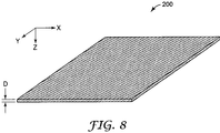
- FIG. 8 is a simplified representation of a knitted fabric filter media 200, and identifies the X, Y, and Z directions; the knitted fabric filter media defines a depth (or thickness) dimension D along the Z axis.
- the pore geometry of woven mesh filters is effectively limited to a parallelogram (e.g., square or rectangular) shape in the X, Y plane that is uniform or constant in the depth direction.
- a parallelogram e.g., square or rectangular
- some or all of the pores provided by the knitted fabric filters of the present disclosure can have a geometry other than parallelogram, including regular or uniform shapes (e.g., triangle, pentagon, etc.) and irregular or complex shapes.
- regular or uniform shapes e.g., triangle, pentagon, etc.
- irregular or complex shapes e.g., represented by FIG.
- the shape or geometry of the pores or openings in the X, Y plane is relatively uniform or consistent throughout the knitted fabric (e.g., with the non-limiting example knitted fabric of FIG. 7 , the pores all have a geometry approximating a pentagon).
- two or more differently-shaped pores are provided across the knitted fabric filter.
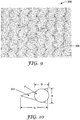
- a micrograph of a knitted fabric material 300 useful as or with the reservoir filters of the present disclosure is provided in FIG. 9 (it being understood that a major face of the knitted fabric material 300 is visible in FIG. 9 , such that the descriptions below with respect to pore shapes are relative to the X, Y plane).
- the knitting technique utilized with the knitted fabric material 300 generates a repeating pattern of several differently-shaped pores or openings, such as first pores 302, second pores 304, third pores 306, and fourth pores 308.
- An ability of the knitted fabric material 300 to filter or remove particles of interest from liquid is a function of the larger size pores; thus, because a size of the fourth pores 308 is significantly less than that of the first-third pores 302-306, the fourth pores 308 have minimal relevance.
- the first pores 302 have a substantially triangular shape or geometry, and an open area greater than that of the second and third pores 304, 306.
- the second pores 304 have a trapezoid shape or geometry, and an open area greater than that of the third pores 306.
- the third pores 306 have a rectangular shape or geometry. In other embodiments, other pore geometries or shapes can be provided.
- FIG. 9 further reflects that the knitted fabric filter media of the present disclosure can provide a controlled or non-random distribution of differently sized or shaped pores across the filter.
- conventional woven mesh filters are inherently limited to a uniform distribution of identically sized or shaped pores.
- the controlled distribution of differently sized or shaped pores optionally embodied by knitted fabric filter media of the present disclosure can enhance overall filter performance, such as by removing particles of interest with lesser overall effect on liquid flow rate (as compared to conventional woven mesh filters).
- the pore size or shape can by dynamically adjusted across or along the knitted fabric filter media via the selected knitting process, again leading to possible performance improvements over conventional woven mesh filters.
- filtration efficacy of a particular knitted fabric filter media is primarily a function of the largest sized pores provided by the knitted fabric filter (i.e., if the filter is intended to remove particles of a specified minimum diameter or larger, then the largest sized pores associated with that filter should be no greater than the specified minimum diameter).
- the first pores 302 are of interest with respect to filter viability, presenting an open area greater than that of the second-fourth pores 304-308.
- the shape of the first pores 302 can be viewed as defining a height dimension H greater than a base dimension B. As schematically reflected in FIG. 10 , a particle P having a diameter D slightly less than the height dimension H will not pass through the first pore 302 due to the tapered, triangular shape. Instead, the effective porosity (for purposes of particle filtration) provided by the first pores 302 is on the order of one-half the height H multiplied by the base B.
- the triangular shaped pores associated with some knitted fabric filter media of the present disclosure can have dimensions larger than a specified minimum particle diameter (and are thus more easily manufactured). Similar analyses apply to other pore shapes of the knitted fabric filter media of the present disclosure, such as the second and third pores 304, 306 of FIG. 9 .
- knitted fabric filter media of the present disclosure can incorporate geometry features in the Z or depth dimension differing from the relatively uniform Z depth dimension geometry provided by conventional woven mesh filters.
- the selected knitting process can produce knitted fabric filter media with thickness or depth dimensions greater than conventional woven mesh filter media; depth dimensions or geometries that vary (e.g., in a controlled or non-random distribution or manner) across the knitted fabric filter media; tortuous pore or aperture paths in the depth dimension that may assist with the capture of more complex particle shapes (as compared to a simply two dimensional aperture or pore as found with conventional woven mesh filters), etc.
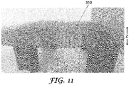
- FIG. 11 is a photograph of a knitted fabric filter media 310 in accordance with principles of the present disclosure; the view of FIG. 11 is primarily from a side of the knitted fabric filter media 310 and thus is indicative of the Z axis (along which the depth dimension D ( FIG. 8 ) is defined). As implicated by FIG. 11 , features of the knitted fabric filter media 310 project in the Z dimension, creating tortuous pores or aperture paths in the Z or depth dimension that vary across the knitted fabric filter media 310.
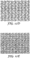
- the format or pattern embodied by the knitted fabric filter media of the present disclosure can assume a wide variety of other forms. Non-limiting examples of other knitted arrangements in accordance with principles of the present disclosure are provided in FIGS. 12A-12E .
- the knitted fabric filter media of the present disclosure include two (or more) knitted fabric layers. With these optional constructions, the two or more layers generate a depth filtration media. Further, with embodiments in which the knitted fabric layers comprising the filter media have non-uniform pores and/or pores of a larger-than-desired size, the knitted fabric layers can be strategically arranged relative to one another to reduce the effective size of any larger pores within any one particular layer.
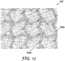
- FIG. 13 is a micrograph of another, non-limiting embodiment filter media 320 in accordance with principles of the present disclosure, and comprises two layers 300a, 300b of the knitted fabric material 300 described above with respect to FIG. 9 .
- the layers 300a, 300b are arranged orthogonally relative to one another, with the result that fibers or threads in one layer "cross over" various pores in the other layer, thereby reducing the effective open area or size of any one particular opening.
- Other multiple layer knitted fabric filter media configuration are envisioned, with the layers having the same or different construction.
- the multiple layers can each provide course/fine holes; larger holes would protect the finer media from plugging, preserving their functionality and making the resultant filter more effective.
- the knitted fabric comprising the knitted fabric filter media can be generated by a circular knitting (or similar) process, resulting in a cylindrical or tubular construction; the cylindrical construction differentiates from the flat or planar nature of conventional woven mesh filters, potentially providing more surface area and less surface tension concerns.
- the knitted fabric filter media can be manipulated geometrically, such as with pleating, corrugation, etc., forming into a conical shape, and the like.
- the knitted fabric filter media of the present disclosure can employ a wide variety of different types of base filaments or fibers.
- a nylon filament is used to form the knitted fabric filter media, akin to nylon filaments used with conventional woven mesh filter media.
- Alternative filament constructions are readily incorporated into the knitted fabric filters of the present disclosure such that filament types other than, or in addition to, nylon filaments are readily available and can be selected based upon, for example, desired filtering effects, manufacturing speed, costs, etc.
- a multi-filament construction can be incorporated into the knitted fabric filter media of the present disclosure utilizing conventional knitting machinery with minimal effect on mass production costs.
- reservoir lids in accordance with principles of the present disclosure can include a colored knitted fabric filter, with the selected color of the knitted fabric filter being indicative of a feature of the knitted fabric filter and/or of the resultant reservoir assembly, such as filter porosity akin to color schemes conventionally incorporated into existing reservoir lids (e.g., a first color designates 125 micron porosity rating, and a second color designates a 200 micron porosity rating).
- filter porosity akin to color schemes conventionally incorporated into existing reservoir lids (e.g., a first color designates 125 micron porosity rating, and a second color designates a 200 micron porosity rating).
- coloring of the lid or a filter holder itself is not required (as instead, the colored knitted fabric filter carried by the lid visually indicate a porosity rating), thus presenting a cost savings.
- conventional woven mesh filters cannot readily incorporate the differing filament(s) constructions of the knitted fabric filter media of the present disclosure, especially on a mass production basis. Due to the ease with which most industrial knitting machines can receive, handle and process different filament types during a single, continuous production run in forming a knitted fabric (as compared to industrial weaving machines), filaments utilized in forming a particular knitted fabric filter media can quickly easily be changed during continuous operation. In contrast, mass production operation of industrial weaving machinery in the manufacture of conventional woven mesh filter media requires batch processing to be economically viable. With batch processing, an extremely long length of a single filament type is supplied to the weaving machinery and is the basis for the production run size.
- a minimum order quantity is required due to the significant setup time on the weaving machine (pre-winding, rewinding, threading, etc.). Weaving machinery operators are unwilling to stop and restart the weaving machine during a production run in order to introduce a different filament type. Instead, weaving machinery operators strongly prefer to utilize a relative generic or widely-viable filament to generate a large volume of woven mesh filter media that meets industry specifications, and then slit the large volume into smaller quantities for sale to multiple different customers. In addition, knitting may be less expensive than weaving such that some of the knitted fabric filter media of the present disclosure may be less expensive than conventional woven mesh filter media.
- Example knitted fabric filters in accordance with principles of the present disclosure were generated from knitted material samples.
- Example A was a knitted fabric filter media generated from a knitted fabric material obtained from Apex Mills of Inwood, NY ("Apex") available under the trade designation "N98".
- Example B was a knitted fabric filter media generated from a knitted fabric obtained from Apex under the trade designation "NB20”.
- Example C was a knitted fabric filter media generated from a knitted fabric obtained from Apex under the trade designation "NF75”.
- Example D was a knitted fabric filter media generated from a knitted fabric obtained from Apex under the trade designation "NK04".
- Example E was a knitted fabric filter media generated from a knitted fabric obtained from Apex under the trade designation "NX91".
- Example F was a knitted fabric filter media generated from a knitted fabric obtained from Apex under the trade designation "NZ11".
- Example G was a knitted fabric filter media generated from a knitted fabric obtained from Sitip S.p.A. Industrie Tessili of Cene (BG), Italy ("Sitip") available under the trade designation "Cam B 45/50”.
- Example H was a knitted fabric filter media generated from a knitted fabric obtained from Sitip under the trade designation "Cam SPB 90/95”.
- Example I was a knitted fabric filter media generated from a knitted fabric obtained from Sitip under the trade designation "Tel 28/3".
- sample filters of Examples A-I were each assembled to, and used as the filter of, a spray gun reservoir assembly available from 3M Company, St. Paul, MN under the trade designation 3MTM PPSTM Type H/O Pressure Cup (including a liner and outer container).
- the microcontroller was programmed to control pressure at the reservoir assembly via the air pump, maintaining a constant pressure inside the sealed cup (the PC microcontroller reads pressure from the pressure sensor and adjusts the air pump accordingly).
- a pressure set point of 6 kPa was used as the pressure set point for the testing.
- high velocity atomization air creates a net vacuum on the spray gun system, which augments gravity-based flow forces and aids in achieving desirable flow rates during spraying.
- typical mass flow rates during air impingement spray with typical automotive paints range from 3 - 5 g/sec.
- the spray gun's trigger secured in the fully pulled position, allowing a stream of the sample paint to be expelled from the sample reservoir assembly, into and through the spray gun, and from the nozzle outlet orifice of the gun into a reservoir on a digital laboratory scale.
- the mass and elapsed time were recorded via a seral protocol at a sampling rate of approximately 100 Hz.
- the mean steady state slope of mass per time was extracted in order to determine the mass flow rate.
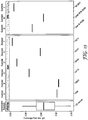
- FIG. 15 Results of the flow rate testing are provided in FIG. 15 .
- the flow rate of a Comparative Example reservoir assembly (or "PPS") commercially available under the trade designation 3MTM PPSTM Type H/O Pressure Cup and containing a 125 micron woven mesh filter was also tested, with results reported in FIG. 15 .
- the knitted fabric filters of the Examples generated flow ranges predominantly overlapping those obtained for the Comparative Example, indicating that although the knitted fabric filters of Examples A-I may have decreased open area (as compared to the Comparative Example), the knitted fabric filters of the present disclosure should not pose an issue for paint flow.
- Thickness (Z or depth dimension) measurements were obtained for the knitted fabric filter media of Examples A-I using a Mitutoyo 500-196-30 Advanced Onsite Sensor (AOS) digital caliper. In each instance, thickness was measured at least three times, and if there was a difference between individual measurements, minimum and maximum values were recorded. The results are reported in the Table below. Thickness measurements were similarly obtained for the knitted fabric filter media of FIG. 11 ("Example J"). In this regard, and as evidenced by the photograph of FIG.
- the knitted fabric filter media of Example J is "lofty" with loop-like structures projecting in the Z dimension; thickness measurements were obtained under first testing conditions in which the digital caliper barely touched the opposing faces of the media (such that loop-like structures were minimally compressed, if at all), and under second testing conditions in which the digital caliper was firmly compressed on to the media.
- the results are reported in the Table below, including thickness measurements under the first testing condition ("Test 1") and under the second testing condition ("Test 2").
- Example A 0.32 - 0.33
- Example B 0.47 - 0.49
- Example C 0.15 - 0.17
- Example D 0.18 - 0.20
- Example E 0.21
- Example F 0.21 - 0.22
- Example G 0.21
- Example H 0.28 Example I 0.25
- Example J (Test 2) 0.62 - 0.67 CE1 0.10 CE2 0.18 - 0.19
Landscapes
- Knitting Of Fabric (AREA)
- Filtering Materials (AREA)
- Containers And Packaging Bodies Having A Special Means To Remove Contents (AREA)
- Nozzles (AREA)
Description
- The present disclosure relates to liquid spraying apparatuses, such as spray guns. More particularly, it relates to the filters useful with spray guns, and in particular with reservoirs containing the liquid to be sprayed.
-
DE 10 2010 012 541 A1 discloses a cup having a color cup with an upper cup edge at which a thread is arranged, and a cover that is screwed on the thread at the upper cup edge. A circulating radially extending sealing bar is provided at the color cup and arranged below the thread. The cover has an outer sealing bar that cooperates with the radially extending sealing bar, and an internal sealing bar that cooperates with an inner side of the color cup below the thread at the cover. The radially extending sealing bar radially projects over maximum radial extension of the cover. - Spray guns are widely used to apply a liquid to a substrate in a variety of industries. In the known spray guns, the liquid is contained in a reservoir attached to the gun from where it is fed to a spray nozzle. On emerging from the spray nozzle, the liquid is atomized and forms a spray with compressed air supplied to the nozzle. The liquid may be gravity fed or suction fed or, more recently, pressure fed by an air bleed line to the reservoir from the compressed air line to the spray gun, or from the spray gun itself.
- A common application of spray guns is in vehicle body repair shops when re-spraying a vehicle that has been repaired following an accident. A typical paint finish may require application of a primer, sealer, base coat, top coat and a clear coat or clear lacquer. The presence of contaminants such as solid particles in the liquid to be sprayed can spoil the paint finish and extensive re-working (e.g., sanding, compounding, and polishing; defect removal; de-nibbing; etc.) is required to achieve an acceptable paint finish. In some instances, the solid particles may cause blockage of the spray gun itself requiring stripping down and cleaning of the spray gun to remove the blockage. In addition, the blockage may have an adverse effect on the spray and render the resulting paint finish unacceptable so that extensive re-working is again required to produce an acceptable paint finish. Re-working of the paint finish and, where required, unblocking of the spray gun, adds to costs both in terms of materials and time.
- It is already known to provide a filter in the reservoir to remove contaminants as the liquid is withdrawn from the reservoir during operation of the spray gun. For example, one popular reservoir design is the PPS™ Paint Preparation System available from 3M Company of St. Paul, MN, and includes a reusable outer container or cup, an open-topped liner, and a lid. A filter is carried by the lid. The liner fits into the outer container, and paint (or other liquid) that is to be sprayed is contained within the liner. The lid is assembled with the liner and provides a spout or conduit through which the contained paint is conveyed. In this regard, the contained liquid must pass through or interface with the filter when flowing to the spout. A number of other reservoir designs also incorporate a filter.
- Regardless of an exact design of the spray gun reservoir, the in-lid filter is conventionally a woven mesh material or media, normally a single layer or sheet of woven nylon mesh. The woven mesh filter is formatted to provide a uniform pattern of essentially identically sized and shaped pores. While well-accepted as an in-lid, spray gun reservoir filter, it can be difficult for some manufacturers to reliably produce silicone-free woven nylon mesh filters on a mass production basis due to the common industry use of silicone lubricants; the presence of silicone in the filter can negatively affect some paint finishing products.
- As a point of reference, paint manufacturers specify at least a minimum pore size or pore size range for filters to be used with a particular paint product (e.g., so as to ensure that necessary constituents of the paint product are not removed by the filter). A specified minimum pore size for many paint finishing products may be in the range of about 80 - 500 micron, with either 125 micron or 200 micron meeting the criteria of most paint suppliers. Reservoir manufacturers, in turn, endeavor to provide end users with filter options (e.g., in-lid filter) commensurate with the paint manufacturer's specifications. Thus, for example, users of the PPS™ Paint Preparation System can select a lid carrying a 125 micron filter or a lid carrying a 200 micron filter. In addition to product labeling, reservoir manufacturers may incorporate different color schemes into the filter-carrying lid for a user to more quickly identify the pore size of the particular in-lid filter.
- The inventors of the present disclosure recognized that a need exists for spray gun reservoir filters that overcome one or more of the above-mentioned problems.
- Some aspects of the present disclosure are directed toward a spray gun reservoir including a cup, a lid, and a filter. The cup defines an internal containment volume. The lid defines an outlet. The filter is disposed between the containment volume and the outlet such that liquid flow from the containment volume to the outlet interfaces with the filter. The filter includes a knitted fabric filter media. In some embodiments, the knitted fabric filter media includes filaments knitted in a pattern defining a plurality of pores, and is formed, at least in part, by warp knitting, alternatively by weft knitting. In related embodiments, at least some of the pores are non-square in shape, including a triangular shape. In other embodiments, the pores are distributed across the knitted fabric filter media in a controlled, non-random manner. In yet other embodiments, the knitted fabric filter media includes first and second layers of knitted fabric arranged to define a depth filter.
- As used herein, the term "liquid" refers to all forms of flowable material that can be applied to a surface using a spray gun (whether or not they are intended to color the surface) including (without limitation) paints, primers, base coats, lacquers, varnishes and similar paint-like materials as well as other materials, such as adhesives, sealer, fillers, putties, powder coatings, blasting powders, abrasive slurries, mold release agents and foundry dressings which may be applied in atomized or non-atomized form depending on the properties and/or the intended application of the material and the term "liquid" is to be construed accordingly.
-
-
FIG. 1 is a perspective view of a spray gun assembly including a spray gun and a reservoir; -
FIG. 2 is a perspective view of the reservoir shown inFIG. 1 separate from the spray gun; -
FIG. 3 is a longitudinal cross-sectional view of the reservoir ofFIG. 2 and illustrating a filter in accordance with principles of the present disclosure; -
FIG. 4 is a simplified, enlarged plan view of a portion of a knitted fabric material useful with the filters of the present disclosure; -
FIG. 5 is a simplified, enlarged plan view of a portion of another knitted fabric material useful with the filters of the present disclosure; -
FIG. 6 is a simplified, enlarged plan view of a portion of another knitted fabric material useful with the filters of the present disclosure; -
FIG. 7 illustrates a simplified comparison of a woven fabric and a knitted fabric; -
FIG. 8 is a simplified perspective view of a knitted fabric filter media in accordance with principles of the present disclosure; -
FIG. 9 is a micrograph of a portion of another knitted fabric filter in accordance with principles of the present disclosure; -
FIG. 10 schematically illustrates a relationship of a particle relative to a pore provided with some knitted fabric filters of the present disclosure; -
FIG. 11 is a photograph of another knitted fabric filter material useful with the filters of the present disclosure; -
FIGS. 12A-12E are micrographs of knitted fabric materials useful with the filters of the present disclosure; -
FIG. 13 is a micrograph of a portion of another knitted fabric filter in accordance with principles of the present disclosure; -
FIG. 14 schematically illustrates arrangement of components of a flow rate test described in the Examples section; and -
FIG. 15 is a graph of the results of the flow rate testing described in the Examples section. - Aspects of the present disclosure are directed toward filters useful with spray gun paint systems, for example filters provided with a reservoir component of a spray gun paint system. By way of background,
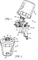
FIG. 1 depicts a spraygun paint system 20 including aspray gun 30 of a gravity-feed type and areservoir 32. Thegun 30 includes abody 40, ahandle 42, and aspray nozzle 44 at a front end of thebody 40. Thegun 30 is manually operated by atrigger 46 that is pivotally mounted on the sides of thebody 40. An inlet port 48 (referenced generally) is formed in or carried by thebody 40, and is configured to establish a fluid connection between an interior spray conduit (hidden) of thespray gun 30 and thereservoir 32. Thereservoir 32 contains liquid (e.g., paint) to be sprayed, and is connected to theinlet port 48 either directly or by way of anoptional adaptor 50. In use, thespray gun 30 is connected via aconnector 52 at a lower end of thehandle 42 to a source of compressed air (not shown). Compressed air is delivered through thegun 30 when the user pulls on thetrigger 46 and paint is delivered under gravity from thereservoir 32 through thespray gun 30 to thenozzle 44. As a result, the paint (or other liquid) is atomized on leaving thenozzle 44 to form a spray with the compressed air leaving thenozzle 44. - As a point of reference, the present disclosure is not limited to a particular connection format or
connection assembly 60 between thespray gun 30 and thereservoir 32. In general terms, thereservoir 32 includes one or more components establishing a first connection format for connection to thespray gun 30. A complementary, second connection format can be included with theadaptor 50 as assembled between thereservoir 32 and theinlet port 48, and/or with theinlet port 48 itself. - With the above background in mind,
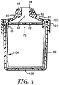
FIGS. 2 and3 illustrate one non-limiting example of thereservoir 32 incorporating or carrying a filter 70 (or "knitted fabric filter") having a knitted fabric filter media 72 (referenced generally) in accordance with principles of the present disclosure. In addition to thefilter 70, thereservoir 32 includes anouter container 80 and alid 82. Thelid 82 has acentral aperture 83 that leads to a spout or feedtube 84 providing a fluid outlet for thereservoir 32. Thefilter 70 is arranged to remove particulate material from the contained liquid (not shown) prior to delivery through thespout 84. Thelid 82 can optionally include one or more additional features or structures, such as askirt 86, and one or more connection features including external ribs orthreads 88 along thespout 84 andhook members spout 84. Once again, a plethora of other connection formats are equally acceptable. Remaining components of thereservoir 32 can assume various forms and are optional. For example, in some embodiments thereservoir 32 further includes aliner 100 and acollar 102. In general terms, theliner 100 fits within the interior of thecontainer 80 and can have anarrow rim 104 at the open end which sits on the top edge of thecontainer 80. Thelid 82 is configured to fit onto or in the open end of theliner 100 to locate the peripheral edge of thelid 82 over therim 104 of theliner 100. The lid/liner assembly is secured in place by theannular collar 102 that releasably engages the container 80 (e.g., threaded interface as shown, snap fit, etc.). - As mentioned above, the
lid 82 forms thespout 84 through which liquid contained by theliner 100 can flow. In use, theliner 100 collapses in an axial direction toward thelid 82 as paint is withdrawn from thereservoir 32. Air is permitted to enter the outer container 80 (in this embodiment through anoptional vent hole 106 in the outer container 80) as theliner 100 collapses. On completion of spraying, thereservoir 32 can be detached from the spray gun 30 (FIG. 1 ), thecollar 102 released and the lid/liner assembly removed from theouter container 80 in one piece. Theouter container 80 and thecollar 102 are left clean and ready for re-use with afresh liner 100 andlid 82. In this way, excessive cleaning of thereservoir 32 can be avoided. - In other embodiments, the reservoirs of the present disclosure need not include the
liner 100 and/or thecollar 102. In some embodiments, the reservoir need not include the outer container (for example, the lid and liner may be separable or removable from the outer container such that the outer container is not needed during spraying). The knitted fabric filters and knitted fabric filter media of the present disclosure can be implemented with these and/or a plethora of other reservoir configurations that may or may not be directly implicated by the figures. For example, the knitted fabric filters and knitted fabric filter media of the present disclosure need not necessarily have the relatively planar format implicated byFIG. 3 and can instead be shaped in accordance with a particular reservoir design (e.g. cup-shaped, etc.) and/or may be pleated or corrugated, etc. In other embodiments, the knitted fabric filters of the present disclosure need not be integrally formed with the lid or other structural components of a corresponding reservoir assembly. In other embodiments, the knitted fabric filters of the present disclosure can alternatively be attached or preassembled to the end of a paint supply line or pouch, etc., and in turn connected to the spray gun paint inlet port. In this way, paint could be supplied directly to the spray gun without the need for other reservoir components. In yet other embodiments, the knitted fabric filters and knitted fabric filter media of the present disclosure can be employed to filter directly out of a paint dispensing mechanism. For example, knitted fabric filters and knitted fabric filter media of the present disclosure can be formed as cone-type filter; paint or other liquid can be pre-mixed and then poured through the cone-type filter into the dispensing cup/spray gun reservoir, thereby eliminating the need for an additional filter with the spray gun reservoir. Other paint filter and paint strainer embodiments can also be employed. - The knitted
fabric filter media 72 includes or comprises a knit fabric or knitted fabric. One or more additional components can be included to support the knittedfabric filter media 72 as part of thefilter 70. In contrast to a woven mesh or a woven fabric (that are otherwise excluded from the definition of "knitted fabric" as used throughout the present disclosure), with a knitted fabric, the filament(s) or thread(s) comprising the material follow a looped or meandering path (or "course"), forming symmetric loops (also called "blights") above and below the mean path of the filament. "Course" is the horizontal row of loops across the width of the fabric produced by adjacent needles during the same knitting cycle. The number of courses determines the length of the fabric. The vertical column of loops in a knitted fabric is referred to as the "wale". Wales are generally produced by the same needle knitting at successive knitting cycles. The number of wales determines the width of the fabric. - Knitted fabric can generally be classified by warp knitting or weft knitting. Warp knitting is a method of making fabric by normal knitting means in which the loop made from each warp filament or thread is formed substantially along the length of the fabric. In a warp knitting structure, each loop in the horizontal direction is made from a different fiber thread.
FIG. 4 illustrates the stitch pattern of one basic warp knitted fabric in which a first filament orstrand 150 follows a zig zag-like path, with each loop of thefirst filament 150 securing to a loop of an adjacentsecond filament 152 orthird filament 154. In some embodiments, the knitted fabric filter media of the present disclosure incorporates a type of warp knitting that otherwise minimizes possible unraveling during cutting/converting processes. - Alternatively or in addition, the knitted fabric filter media of the present disclosure can incorporate weft knitting. Weft knitting is a method of making a fabric by normal knitting means in which the loop made from each weft thread or filament is formed substantially along the length of the fabric, characterized by the fact that each warp thread is fed more or less in line with the direction in which the fabric is produced. For example,
FIG. 5 illustrates the stitch pattern of one basic weft knitted fabric in which loops of a first filament or strand 160 have been pulled through the loops of a second filament orstrand 162; further, loops of a third filament or strand 164 have been pulled through the loops of thefirst filament 160. - Using industrial knitting machinery (e.g., weft knitting machines such as flat bar knitting machines, straight bar knitting machines, circular knitting machines, circular bearded single knitting machine; warp knitting machines such as rachel knitting machines and tricot knitting machines), a plethora of different knitted fabric configurations can be achieved and are useful as the filters of the present disclosure. For example, an interlock knit (
FIG. 6 ) can be generated by long and short needles arranged alternately in both dial and cylinder components of the circular knitting machine; the needles in the dial and cylinder are also positioned in direct alignment. When the long and short needles knit in alternate feeds in both needle housings, a knitted fabric with a type of cross 1 x 1 rib effect is produced. One or more other common knitted fabric stitch patterns or styles may be useful with the knitted fabric filters of the present disclosure, including (but not limited to) weft plain stitch, rib stitch, purl stitch, chain stitch, pillar stitch, tricot stitch, satin tricot stitch, double loop stitch, derivative stitch, interlock stitch, cord stitch, tuck stitch, half cardigan stitch, full cardigan stitch, blister stitch, plating stitch, weft laid - in stitch, laying - in stitch, jacquared stitch, terry stitch, pile stitch, lace stitch, racked stitch, locknit stitch, reverse locknit, atlas stitch, queen's cord, miss-lapping stitch, miss-pressing stitch, and fall-plate stitch. - Regardless of exact form, the inventors of the present disclosure have surmised and surprisingly discovered that knitted fabric can be used as the spray gun reservoir filter media 72 (
FIG. 3 ), in place of conventional woven mesh filters. As a point of reference, while knitted fabrics have been considered as media separation for tangential flow (i.e., to maintain spacing between adjacent layers of media, which spacing would otherwise collapse under differential pressure, as well as turbulence and z-axis mixing of the material), knitted fabric is not commonly understood or viewed as being a viable small particle filtration media, especially in the context of filtering small particles from painting products as part of a spray gun reservoir. The differences between a woven material and a knitted material are generally reflected byFIG. 7 . Perhaps due to the substantially uniform shape, size and distribution of the openings or pores that is readily provided by woven mesh, woven mesh filters have been viewed as the only viable option for some time. Moreover, because knitted fabrics are typically characterized by complexly-shaped openings or "pores," knitted fabric manufacturers do not normally consider or specify pore size as a meaningful attribute of the knitted fabric; absent this information or other recognition by knitted fabric manufacturers as to the importance of pore size, those in the paint spray gun industries have not previously considered knitted fabric as a possible spray gun reservoir filter material. However, the inventors of the present disclosure have surprisingly discovered and surmised that not only can the knitted fabric filters of the present disclosure achieve porosity characteristics (e.g., pore size) in accord with those of woven mesh filters conventionally used with spray gun reservoirs in the automotive painting industry, but opportunities for improvements or advantages over woven mesh filters exist. - For example, due to the multiplicity of different knitting types, patterns or formats available with knitted fabrics, a plethora of different opening or pore geometries can be provided in one or both of the X, Y plane (i.e., plane parallel to the opposing major faces of the knitted fabric) and the Z or depth direction. By way of clarification,
FIG. 8 is a simplified representation of a knittedfabric filter media 200, and identifies the X, Y, and Z directions; the knitted fabric filter media defines a depth (or thickness) dimension D along the Z axis. Returning toFIG. 7 , in contrast to some of the knitted fabric filter media of the present disclosure, the pore geometry of woven mesh filters is effectively limited to a parallelogram (e.g., square or rectangular) shape in the X, Y plane that is uniform or constant in the depth direction. With respect to a shape of the pore(s) in the X, Y plane, some or all of the pores provided by the knitted fabric filters of the present disclosure can have a geometry other than parallelogram, including regular or uniform shapes (e.g., triangle, pentagon, etc.) and irregular or complex shapes. With some relatively simple knitted fabric formats (e.g., represented byFIG. 7 that otherwise illustrates the X, Y plane), the shape or geometry of the pores or openings in the X, Y plane is relatively uniform or consistent throughout the knitted fabric (e.g., with the non-limiting example knitted fabric ofFIG. 7 , the pores all have a geometry approximating a pentagon). With many other configurations, two or more differently-shaped pores are provided across the knitted fabric filter. For example, a micrograph of aknitted fabric material 300 useful as or with the reservoir filters of the present disclosure is provided inFIG. 9 (it being understood that a major face of the knittedfabric material 300 is visible inFIG. 9 , such that the descriptions below with respect to pore shapes are relative to the X, Y plane). The knitting technique utilized with the knittedfabric material 300 generates a repeating pattern of several differently-shaped pores or openings, such asfirst pores 302,second pores 304,third pores 306, andfourth pores 308. An ability of the knittedfabric material 300 to filter or remove particles of interest from liquid is a function of the larger size pores; thus, because a size of thefourth pores 308 is significantly less than that of the first-third pores 302-306, thefourth pores 308 have minimal relevance. The first pores 302 have a substantially triangular shape or geometry, and an open area greater than that of the second andthird pores third pores 306 have a rectangular shape or geometry. In other embodiments, other pore geometries or shapes can be provided. By formatting two or more differently shaped pores into the knitted fabric filters of the present disclosure, filtration effects otherwise not available with conventional woven mesh filters are achieved. - The non-limiting example of
FIG. 9 further reflects that the knitted fabric filter media of the present disclosure can provide a controlled or non-random distribution of differently sized or shaped pores across the filter. In contrast, conventional woven mesh filters are inherently limited to a uniform distribution of identically sized or shaped pores. The controlled distribution of differently sized or shaped pores optionally embodied by knitted fabric filter media of the present disclosure can enhance overall filter performance, such as by removing particles of interest with lesser overall effect on liquid flow rate (as compared to conventional woven mesh filters). Moreover, the pore size or shape can by dynamically adjusted across or along the knitted fabric filter media via the selected knitting process, again leading to possible performance improvements over conventional woven mesh filters. - It is recognized that filtration efficacy of a particular knitted fabric filter media is primarily a function of the largest sized pores provided by the knitted fabric filter (i.e., if the filter is intended to remove particles of a specified minimum diameter or larger, then the largest sized pores associated with that filter should be no greater than the specified minimum diameter). Thus, with the non-limiting example of
FIG. 9 , thefirst pores 302 are of interest with respect to filter viability, presenting an open area greater than that of the second-fourth pores 304-308. Due to the triangular shape of thefirst pores 302, however, it is surmised that less than an entirety of the open area of thefirst pores 302 is relevant to the determination of filtration efficacy, and in particular the particle size that will pass or not pass through the first pores 302. The shape of thefirst pores 302 can be viewed as defining a height dimension H greater than a base dimension B. As schematically reflected inFIG. 10 , a particle P having a diameter D slightly less than the height dimension H will not pass through thefirst pore 302 due to the tapered, triangular shape. Instead, the effective porosity (for purposes of particle filtration) provided by thefirst pores 302 is on the order of one-half the height H multiplied by the base B. Thus, the triangular shaped pores associated with some knitted fabric filter media of the present disclosure can have dimensions larger than a specified minimum particle diameter (and are thus more easily manufactured). Similar analyses apply to other pore shapes of the knitted fabric filter media of the present disclosure, such as the second andthird pores FIG. 9 . - In addition or as an alternative to shaping of the pore(s) in the X, Y plane, knitted fabric filter media of the present disclosure can incorporate geometry features in the Z or depth dimension differing from the relatively uniform Z depth dimension geometry provided by conventional woven mesh filters. The selected knitting process can produce knitted fabric filter media with thickness or depth dimensions greater than conventional woven mesh filter media; depth dimensions or geometries that vary (e.g., in a controlled or non-random distribution or manner) across the knitted fabric filter media; tortuous pore or aperture paths in the depth dimension that may assist with the capture of more complex particle shapes (as compared to a simply two dimensional aperture or pore as found with conventional woven mesh filters), etc. By way of non-limiting example,
FIG. 11 is a photograph of a knittedfabric filter media 310 in accordance with principles of the present disclosure; the view ofFIG. 11 is primarily from a side of the knittedfabric filter media 310 and thus is indicative of the Z axis (along which the depth dimension D (FIG. 8 ) is defined). As implicated byFIG. 11 , features of the knittedfabric filter media 310 project in the Z dimension, creating tortuous pores or aperture paths in the Z or depth dimension that vary across the knittedfabric filter media 310. - The format or pattern embodied by the knitted fabric filter media of the present disclosure can assume a wide variety of other forms. Non-limiting examples of other knitted arrangements in accordance with principles of the present disclosure are provided in
FIGS. 12A-12E . - In other embodiments, the knitted fabric filter media of the present disclosure include two (or more) knitted fabric layers. With these optional constructions, the two or more layers generate a depth filtration media. Further, with embodiments in which the knitted fabric layers comprising the filter media have non-uniform pores and/or pores of a larger-than-desired size, the knitted fabric layers can be strategically arranged relative to one another to reduce the effective size of any larger pores within any one particular layer. For example,
FIG. 13 is a micrograph of another, non-limitingembodiment filter media 320 in accordance with principles of the present disclosure, and comprises twolayers fabric material 300 described above with respect toFIG. 9 . Thelayers - The knitted fabric filter media of the present disclosure can employ a wide variety of different types of base filaments or fibers. In some embodiments, a nylon filament is used to form the knitted fabric filter media, akin to nylon filaments used with conventional woven mesh filter media. Alternative filament constructions are readily incorporated into the knitted fabric filters of the present disclosure such that filament types other than, or in addition to, nylon filaments are readily available and can be selected based upon, for example, desired filtering effects, manufacturing speed, costs, etc. For example, a multi-filament construction can be incorporated into the knitted fabric filter media of the present disclosure utilizing conventional knitting machinery with minimal effect on mass production costs. Moreover, filaments that have been pigmented or dyed to a desired, distinct color can be incorporated into the knitted fabric filter media of the present disclosure using existing industrial knitting machines. With these and related embodiments, reservoir lids in accordance with principles of the present disclosure can include a colored knitted fabric filter, with the selected color of the knitted fabric filter being indicative of a feature of the knitted fabric filter and/or of the resultant reservoir assembly, such as filter porosity akin to color schemes conventionally incorporated into existing reservoir lids (e.g., a first color designates 125 micron porosity rating, and a second color designates a 200 micron porosity rating). Unlike existing reservoir lids, however, coloring of the lid or a filter holder itself is not required (as instead, the colored knitted fabric filter carried by the lid visually indicate a porosity rating), thus presenting a cost savings.
- As a point of reference, conventional woven mesh filters cannot readily incorporate the differing filament(s) constructions of the knitted fabric filter media of the present disclosure, especially on a mass production basis. Due to the ease with which most industrial knitting machines can receive, handle and process different filament types during a single, continuous production run in forming a knitted fabric (as compared to industrial weaving machines), filaments utilized in forming a particular knitted fabric filter media can quickly easily be changed during continuous operation. In contrast, mass production operation of industrial weaving machinery in the manufacture of conventional woven mesh filter media requires batch processing to be economically viable. With batch processing, an extremely long length of a single filament type is supplied to the weaving machinery and is the basis for the production run size. A minimum order quantity is required due to the significant setup time on the weaving machine (pre-winding, rewinding, threading, etc.). Weaving machinery operators are unwilling to stop and restart the weaving machine during a production run in order to introduce a different filament type. Instead, weaving machinery operators strongly prefer to utilize a relative generic or widely-viable filament to generate a large volume of woven mesh filter media that meets industry specifications, and then slit the large volume into smaller quantities for sale to multiple different customers. In addition, knitting may be less expensive than weaving such that some of the knitted fabric filter media of the present disclosure may be less expensive than conventional woven mesh filter media.
- As a further benefit, many industrial weaving machines inherently and undesirably introduce siloxane or other silicone material into the woven mesh during production. It is surmised that conventional industrial knitting machines do not give rise to a similar concern, such that the knitted fabric filters of the present disclosure may be consistently produced as a silicone free material in some embodiments.
- Objects and advantages of the present disclosure are further illustrated by the following non-limiting examples and comparative examples. The particular materials and amounts thereof recited in these examples, as well as other conditions and details, should not be construed to unduly limit the present disclosure.
- Example knitted fabric filters in accordance with principles of the present disclosure were generated from knitted material samples. Example A was a knitted fabric filter media generated from a knitted fabric material obtained from Apex Mills of Inwood, NY ("Apex") available under the trade designation "N98". Example B was a knitted fabric filter media generated from a knitted fabric obtained from Apex under the trade designation "NB20". Example C was a knitted fabric filter media generated from a knitted fabric obtained from Apex under the trade designation "NF75". Example D was a knitted fabric filter media generated from a knitted fabric obtained from Apex under the trade designation "NK04". Example E was a knitted fabric filter media generated from a knitted fabric obtained from Apex under the trade designation "NX91". Example F was a knitted fabric filter media generated from a knitted fabric obtained from Apex under the trade designation "NZ11". Example G was a knitted fabric filter media generated from a knitted fabric obtained from Sitip S.p.A. Industrie Tessili of Cene (BG), Italy ("Sitip") available under the trade designation "Cam B 45/50". Example H was a knitted fabric filter media generated from a knitted fabric obtained from Sitip under the trade designation "
Cam SPB 90/95". Example I was a knitted fabric filter media generated from a knitted fabric obtained from Sitip under the trade designation "Tel 28/3". - The sample filters of Examples A-I were each assembled to, and used as the filter of, a spray gun reservoir assembly available from 3M Company, St. Paul, MN under the trade designation 3M™ PPS™ Type H/O Pressure Cup (including a liner and outer container).
- To evaluate the effect the knitted fabric filters of Examples A-I on flow rate, flow testing was simulated using a spray gun testing system depicted in
FIG. 14 that included a spray gun available from 3M Company of St. Paul, MN under the trade designation 3M Accuspray Spray Gun Model HG14 1.4 mm (part number 16577). A jet black paint available from PPG Industries, Inc. of Pittsburgh, PA under the trade designation PPG Envirobase T407 was used as the sample paint for flow rate evaluations. Each sample reservoir assembly as described above was outfitted with a pressure sensor and an air pump that in turn were connected to an Arduino programmable microcontroller. The microcontroller was programmed to control pressure at the reservoir assembly via the air pump, maintaining a constant pressure inside the sealed cup (the Arduino microcontroller reads pressure from the pressure sensor and adjusts the air pump accordingly). A pressure set point of 6 kPa was used as the pressure set point for the testing. As a point of reference, it is known that high velocity atomization air creates a net vacuum on the spray gun system, which augments gravity-based flow forces and aids in achieving desirable flow rates during spraying. It is also known that typical mass flow rates during air impingement spray with typical automotive paints range from 3 - 5 g/sec. By pressurizing the cavity between the sealed container and flexible liner of the reservoir assembly, the vacuum forces created during atomization can be mimicked, avoiding the need to atomize a liquid spray while measuring fluid mass flow. Through trial and error, 6 kPa was determined as producing a flow rate of 3 g/sec in a repeatable manner utilizing a 125 micron woven mesh filter, standard size PPS™ lid and was thus selected as an appropriate pressure set point for testing purposes. With each flow rate test, the spray gun and reservoir cup assembly as inFIG. 14 were held in a rigid fixture, and the spray gun's trigger secured in the fully pulled position, allowing a stream of the sample paint to be expelled from the sample reservoir assembly, into and through the spray gun, and from the nozzle outlet orifice of the gun into a reservoir on a digital laboratory scale. The mass and elapsed time were recorded via a seral protocol at a sampling rate of approximately 100 Hz. At the completion of the test period, the mean steady state slope of mass per time was extracted in order to determine the mass flow rate. - Results of the flow rate testing are provided in
FIG. 15 . The flow rate of a Comparative Example reservoir assembly (or "PPS") commercially available under the trade designation 3M™ PPS™ Type H/O Pressure Cup and containing a 125 micron woven mesh filter was also tested, with results reported inFIG. 15 . As shown, the knitted fabric filters of the Examples generated flow ranges predominantly overlapping those obtained for the Comparative Example, indicating that although the knitted fabric filters of Examples A-I may have decreased open area (as compared to the Comparative Example), the knitted fabric filters of the present disclosure should not pose an issue for paint flow. - Thickness (Z or depth dimension) measurements were obtained for the knitted fabric filter media of Examples A-I using a Mitutoyo 500-196-30 Advanced Onsite Sensor (AOS) digital caliper. In each instance, thickness was measured at least three times, and if there was a difference between individual measurements, minimum and maximum values were recorded. The results are reported in the Table below. Thickness measurements were similarly obtained for the knitted fabric filter media of
FIG. 11 ("Example J"). In this regard, and as evidenced by the photograph ofFIG. 11 , the knitted fabric filter media of Example J is "lofty" with loop-like structures projecting in the Z dimension; thickness measurements were obtained under first testing conditions in which the digital caliper barely touched the opposing faces of the media (such that loop-like structures were minimally compressed, if at all), and under second testing conditions in which the digital caliper was firmly compressed on to the media. The results are reported in the Table below, including thickness measurements under the first testing condition ("Test 1") and under the second testing condition ("Test 2"). For purposes of comparison, thickness measurements where similarly obtained for 125 micron woven mesh filter ("CE1") obtained from a PPS™ Type H/O Pressure Cup and a 200 micron woven mesh filter ("CE2") obtained from a PPS™ Type H/O Pressure Cup, both available from 3M Company, St. Paul, MN. The results are reported in the Table below.TABLE Sample Thickness (mm) Example A 0.32 - 0.33 Example B 0.47 - 0.49 Example C 0.15 - 0.17 Example D 0.18 - 0.20 Example E 0.21 Example F 0.21 - 0.22 Example G 0.21 Example H 0.28 Example I 0.25 Example J (Test 1) 2.6 - 2.8 Example J (Test 2) 0.62 - 0.67 CE1 0.10 CE2 0.18 - 0.19 - Although the present disclosure has been described with reference to preferred embodiments, workers skilled in the art will recognize that changes can be made in form and detail without departing from the scope of the present claims.
Claims (15)
- A spray gun reservoir (32) comprising:a container (80) defining a containment volume;a lid (82) defining an outlet (84); anda filter (70) disposed between the containment volume and the lid (82) such that liquid flowing from the containment volume to the outlet (84) interfaces with the filter (70);characterized in that the filter (70) includes a knitted fabric filter media (72; 200; 310; 320).
- The spray gun reservoir (32) of claim 1, wherein the knitted fabric filter media (32) includes filaments (150; 152; 154; 160; 162; 164) knitted in a pattern including at least one of weft knitting and warp knitting.
- The spray gun reservoir (32) of claims 1 or 2, wherein the knitted fabric filter media (72, 200, 310, 320) includes filaments (150; 152; 154; 160; 162; 164) knitted to one another to define a plurality of pores (302; 304; 306; 308), and further wherein at least some of the plurality of pores (302; 304; 306; 308) have a non-square shape.
- The spray gun reservoir (32) of claim 3, wherein the non-square shape is a triangular shape.
- The spray gun reservoir (32) of claim 4, wherein a size of the triangular shaped pores defines a largest pore size of the knitted fabric filter media (72; 200; 310; 320).
- The spray gun reservoir (32) of any of claims 1-5, wherein the knitted fabric filter media (72; 200; 310; 320) includes filaments (150; 152; 154; 160; 162; 164) knitted to one another to define a plurality of pores (302; 304; 306; 308) including first pores (302) and second pores (304), wherein a size of each of the first pores (302) is greater than a size of each of the second pores (304), and further wherein the first (302) and second pores (304) are distributed across the knitted fabric filter media (72; 200; 310; 320) in a controlled, non-random manner.
- The spray gun reservoir (32) of any of claims 1-6, wherein the knitted fabric filter media (72; 200; 310; 320) includes a first knitted fabric layer (300a) disposed over a second knitted fabric layer (300b).
- The spray gun reservoir (32) of claim 7, wherein a distribution of pores (302; 304; 306; 308) in the first knitted fabric layer (300a) differs from a distribution of pores (302; 304; 306; 308) in the second knitted fabric layer (300b).
- The spray gun reservoir (32) of claims 7 or 8, wherein the first and second knitted fabric layers (300a; 300b) combine to define a depth filter.
- The spray gun reservoir (32) of any of claims 1-9, wherein the knitted fabric filter media (72; 200; 310; 320) includes filaments (150; 152; 154; 160; 162; 164) knitted to one another to define a plurality of pores (302; 304; 306; 308), and further wherein at least one of the plurality of pores (302; 304; 306; 308) defines a tortuous path in a depth dimension of the knitted fabric filter media (72; 200; 310; 320).
- The spray gun reservoir (32) of any of claims 1-10, wherein the knitted fabric filter media (72; 200; 310; 320) includes filaments (150; 152; 154; 160; 162; 164) knitted to one another to define a plurality of pores (302; 304; 306; 308), and further wherein each of the filaments (150; 152; 154; 160; 162; 164) exhibits a color corresponding to a feature of the reservoir (32).
- The spray gun reservoir (32) of claim 11, wherein the feature is a porosity of the knitted fabric filter media (72; 200; 310; 320).
- The spray gun reservoir (32) of any of claims 1-12, wherein the filter (70) is relatively flat.
- The spray gun reservoir (32) of any of claims 1-12, wherein the filter (70) is conical.
- The spray gun reservoir (32) of any of claims 1-12, wherein the filter (70) is cylindrical.
Applications Claiming Priority (2)
| Application Number | Priority Date | Filing Date | Title |
|---|---|---|---|
| US201662371371P | 2016-08-05 | 2016-08-05 | |
| PCT/US2017/044630 WO2018026694A1 (en) | 2016-08-05 | 2017-07-31 | Reservoir filter for hand-held spray guns |
Publications (2)
| Publication Number | Publication Date |
|---|---|
| EP3493915A1 EP3493915A1 (en) | 2019-06-12 |
| EP3493915B1 true EP3493915B1 (en) | 2020-09-30 |
Family
ID=59564256
Family Applications (1)
| Application Number | Title | Priority Date | Filing Date |
|---|---|---|---|
| EP17749583.5A Active EP3493915B1 (en) | 2016-08-05 | 2017-07-31 | Reservoir filter for hand-held spray guns |
Country Status (5)
| Country | Link |
|---|---|
| US (1) | US20190168248A1 (en) |
| EP (1) | EP3493915B1 (en) |
| JP (1) | JP7018930B2 (en) |
| CN (1) | CN109789429A (en) |
| WO (1) | WO2018026694A1 (en) |
Families Citing this family (4)
| Publication number | Priority date | Publication date | Assignee | Title |
|---|---|---|---|---|
| DE112021000095T5 (en) * | 2020-07-02 | 2022-05-05 | Agilent Technologies, Inc. | FILTER ASSEMBLIES, DEPTH INDICATORS, TORQUE-LIMITING FITTINGS, TORQUE INDICATOR FITTINGS AND SYSTEMS WITH THE SAME |
| CN214567471U (en) * | 2021-04-14 | 2021-11-02 | 青岛汉柏塑料科技有限公司 | Reservoir cover, spray gun reservoir connection mechanism and reservoir |
| USD1086371S1 (en) * | 2023-04-25 | 2025-07-29 | 3M Innovative Properties Company | Spray gun trigger |
| DE102024103560A1 (en) * | 2024-02-08 | 2025-08-14 | Sata Gmbh & Co. Kg | Paint cup lid with sieve arrangement |
Family Cites Families (8)
| Publication number | Priority date | Publication date | Assignee | Title |
|---|---|---|---|---|
| US4181514A (en) * | 1978-02-14 | 1980-01-01 | Huyck Corporation | Stitch knitted filters for high temperature fluids and method of making them |
| GB0224698D0 (en) * | 2002-10-24 | 2002-12-04 | 3M Innovative Properties Co | Easy clean spray gun |
| GB0229399D0 (en) | 2002-12-18 | 2003-01-22 | 3M Innovative Properties Co | Drop-in filter for spray gun reservoir |
| US7832567B2 (en) * | 2002-12-18 | 2010-11-16 | 3M Innovative Properties Company | Drop-in filter for spray gun reservoir |
| JP4870466B2 (en) * | 2005-04-20 | 2012-02-08 | 住化農業資材株式会社 | Filtration equipment for liquid smoke system |
| DE102010012541A1 (en) * | 2009-03-26 | 2010-12-16 | Martin Ruda | Mixing cup for spray gun utilized for spraying color on workpiece, has cover with outer sealing bar cooperating with radially extending sealing bar, and internal sealing bar that cooperates with inner side of color cup below thread at cover |
| JP2012040526A (en) | 2010-08-20 | 2012-03-01 | Kurita Water Ind Ltd | Filter for liquid filtration, and liquid filtration method |
| JP2015128739A (en) * | 2014-01-06 | 2015-07-16 | セイコーエプソン株式会社 | Filter, liquid ejection head and liquid ejection device |
-
2017
- 2017-07-31 CN CN201780059431.7A patent/CN109789429A/en active Pending
- 2017-07-31 JP JP2019506371A patent/JP7018930B2/en active Active
- 2017-07-31 WO PCT/US2017/044630 patent/WO2018026694A1/en unknown
- 2017-07-31 US US16/323,469 patent/US20190168248A1/en not_active Abandoned
- 2017-07-31 EP EP17749583.5A patent/EP3493915B1/en active Active
Non-Patent Citations (1)
| Title |
|---|
| None * |
Also Published As
| Publication number | Publication date |
|---|---|
| EP3493915A1 (en) | 2019-06-12 |
| JP7018930B2 (en) | 2022-02-14 |
| CN109789429A (en) | 2019-05-21 |
| US20190168248A1 (en) | 2019-06-06 |
| JP2019531180A (en) | 2019-10-31 |
| WO2018026694A1 (en) | 2018-02-08 |
Similar Documents
| Publication | Publication Date | Title |
|---|---|---|
| EP3493915B1 (en) | Reservoir filter for hand-held spray guns | |
| AU2011279387B2 (en) | System comprising a spray coating device with a liquid supply container | |
| CA2898179C (en) | Valve and filter system for a gravity feed spray container | |
| US10105624B2 (en) | Filter media pack, filter assembly, and method | |
| EP3154707B1 (en) | Nozzle assembly with external baffles | |
| EP3081362B1 (en) | Mesh filter | |
| AU2019201036B2 (en) | Spray tip and method of manufacture | |
| KR20200080334A (en) | Method for producing a foldable textile fabric with electrostatically charged fibers, and a foldable textile fabric | |
| US20170239679A1 (en) | System and method having filter disposed in fluid supply cup | |
| JP3677776B2 (en) | Liquid filling nozzle | |
| JP7511338B2 (en) | Lid for storage container, filter insert member, storage container, and method for manufacturing the lid for the storage container | |
| AU2015201231B2 (en) | System comprising a spray coating device with a liquid supply container | |
| KR101885484B1 (en) | Preparation method of activated carbon and activated carbon obtained thereby | |
| GB2246061A (en) | A device for use in food preparation | |
| JP2022156599A (en) | Spray device and coating method using same | |
| KR20180013432A (en) | Fluid filter for spray machine | |
| HK1185581A (en) | Liquid supply container for a spray coating device |
Legal Events
| Date | Code | Title | Description |
|---|---|---|---|
| STAA | Information on the status of an ep patent application or granted ep patent |
Free format text: STATUS: UNKNOWN |
|
| STAA | Information on the status of an ep patent application or granted ep patent |
Free format text: STATUS: THE INTERNATIONAL PUBLICATION HAS BEEN MADE |
|
| PUAI | Public reference made under article 153(3) epc to a published international application that has entered the european phase |
Free format text: ORIGINAL CODE: 0009012 |
|
| STAA | Information on the status of an ep patent application or granted ep patent |
Free format text: STATUS: REQUEST FOR EXAMINATION WAS MADE |
|
| 17P | Request for examination filed |
Effective date: 20190226 |
|
| AK | Designated contracting states |
Kind code of ref document: A1 Designated state(s): AL AT BE BG CH CY CZ DE DK EE ES FI FR GB GR HR HU IE IS IT LI LT LU LV MC MK MT NL NO PL PT RO RS SE SI SK SM TR |
|
| AX | Request for extension of the european patent |
Extension state: BA ME |
|
| DAV | Request for validation of the european patent (deleted) | ||
| DAX | Request for extension of the european patent (deleted) | ||
| GRAP | Despatch of communication of intention to grant a patent |
Free format text: ORIGINAL CODE: EPIDOSNIGR1 |
|
| STAA | Information on the status of an ep patent application or granted ep patent |
Free format text: STATUS: GRANT OF PATENT IS INTENDED |
|
| INTG | Intention to grant announced |
Effective date: 20200117 |
|
| GRAJ | Information related to disapproval of communication of intention to grant by the applicant or resumption of examination proceedings by the epo deleted |
Free format text: ORIGINAL CODE: EPIDOSDIGR1 |
|
| STAA | Information on the status of an ep patent application or granted ep patent |
Free format text: STATUS: REQUEST FOR EXAMINATION WAS MADE |
|
| GRAP | Despatch of communication of intention to grant a patent |
Free format text: ORIGINAL CODE: EPIDOSNIGR1 |
|
| STAA | Information on the status of an ep patent application or granted ep patent |
Free format text: STATUS: GRANT OF PATENT IS INTENDED |
|
| INTC | Intention to grant announced (deleted) | ||
| INTG | Intention to grant announced |
Effective date: 20200504 |
|
| GRAS | Grant fee paid |
Free format text: ORIGINAL CODE: EPIDOSNIGR3 |
|
| GRAA | (expected) grant |
Free format text: ORIGINAL CODE: 0009210 |
|
| STAA | Information on the status of an ep patent application or granted ep patent |
Free format text: STATUS: THE PATENT HAS BEEN GRANTED |
|
| AK | Designated contracting states |
Kind code of ref document: B1 Designated state(s): AL AT BE BG CH CY CZ DE DK EE ES FI FR GB GR HR HU IE IS IT LI LT LU LV MC MK MT NL NO PL PT RO RS SE SI SK SM TR |
|
| REG | Reference to a national code |
Ref country code: CH Ref legal event code: EP Ref country code: GB Ref legal event code: FG4D |
|
| REG | Reference to a national code |
Ref country code: AT Ref legal event code: REF Ref document number: 1318260 Country of ref document: AT Kind code of ref document: T Effective date: 20201015 |
|
| REG | Reference to a national code |
Ref country code: DE Ref legal event code: R096 Ref document number: 602017024644 Country of ref document: DE |
|
| REG | Reference to a national code |
Ref country code: IE Ref legal event code: FG4D |
|
| PG25 | Lapsed in a contracting state [announced via postgrant information from national office to epo] |
Ref country code: SE Free format text: LAPSE BECAUSE OF FAILURE TO SUBMIT A TRANSLATION OF THE DESCRIPTION OR TO PAY THE FEE WITHIN THE PRESCRIBED TIME-LIMIT Effective date: 20200930 Ref country code: GR Free format text: LAPSE BECAUSE OF FAILURE TO SUBMIT A TRANSLATION OF THE DESCRIPTION OR TO PAY THE FEE WITHIN THE PRESCRIBED TIME-LIMIT Effective date: 20201231 Ref country code: BG Free format text: LAPSE BECAUSE OF FAILURE TO SUBMIT A TRANSLATION OF THE DESCRIPTION OR TO PAY THE FEE WITHIN THE PRESCRIBED TIME-LIMIT Effective date: 20201230 Ref country code: NO Free format text: LAPSE BECAUSE OF FAILURE TO SUBMIT A TRANSLATION OF THE DESCRIPTION OR TO PAY THE FEE WITHIN THE PRESCRIBED TIME-LIMIT Effective date: 20201230 Ref country code: FI Free format text: LAPSE BECAUSE OF FAILURE TO SUBMIT A TRANSLATION OF THE DESCRIPTION OR TO PAY THE FEE WITHIN THE PRESCRIBED TIME-LIMIT Effective date: 20200930 Ref country code: HR Free format text: LAPSE BECAUSE OF FAILURE TO SUBMIT A TRANSLATION OF THE DESCRIPTION OR TO PAY THE FEE WITHIN THE PRESCRIBED TIME-LIMIT Effective date: 20200930 |
|
| REG | Reference to a national code |
Ref country code: AT Ref legal event code: MK05 Ref document number: 1318260 Country of ref document: AT Kind code of ref document: T Effective date: 20200930 |
|
| PG25 | Lapsed in a contracting state [announced via postgrant information from national office to epo] |
Ref country code: LV Free format text: LAPSE BECAUSE OF FAILURE TO SUBMIT A TRANSLATION OF THE DESCRIPTION OR TO PAY THE FEE WITHIN THE PRESCRIBED TIME-LIMIT Effective date: 20200930 Ref country code: RS Free format text: LAPSE BECAUSE OF FAILURE TO SUBMIT A TRANSLATION OF THE DESCRIPTION OR TO PAY THE FEE WITHIN THE PRESCRIBED TIME-LIMIT Effective date: 20200930 |
|
| REG | Reference to a national code |
Ref country code: NL Ref legal event code: MP Effective date: 20200930 |
|
| REG | Reference to a national code |
Ref country code: LT Ref legal event code: MG4D |
|
| PG25 | Lapsed in a contracting state [announced via postgrant information from national office to epo] |
Ref country code: SM Free format text: LAPSE BECAUSE OF FAILURE TO SUBMIT A TRANSLATION OF THE DESCRIPTION OR TO PAY THE FEE WITHIN THE PRESCRIBED TIME-LIMIT Effective date: 20200930 Ref country code: EE Free format text: LAPSE BECAUSE OF FAILURE TO SUBMIT A TRANSLATION OF THE DESCRIPTION OR TO PAY THE FEE WITHIN THE PRESCRIBED TIME-LIMIT Effective date: 20200930 Ref country code: RO Free format text: LAPSE BECAUSE OF FAILURE TO SUBMIT A TRANSLATION OF THE DESCRIPTION OR TO PAY THE FEE WITHIN THE PRESCRIBED TIME-LIMIT Effective date: 20200930 Ref country code: PT Free format text: LAPSE BECAUSE OF FAILURE TO SUBMIT A TRANSLATION OF THE DESCRIPTION OR TO PAY THE FEE WITHIN THE PRESCRIBED TIME-LIMIT Effective date: 20210201 Ref country code: CZ Free format text: LAPSE BECAUSE OF FAILURE TO SUBMIT A TRANSLATION OF THE DESCRIPTION OR TO PAY THE FEE WITHIN THE PRESCRIBED TIME-LIMIT Effective date: 20200930 Ref country code: LT Free format text: LAPSE BECAUSE OF FAILURE TO SUBMIT A TRANSLATION OF THE DESCRIPTION OR TO PAY THE FEE WITHIN THE PRESCRIBED TIME-LIMIT Effective date: 20200930 |
|
| PG25 | Lapsed in a contracting state [announced via postgrant information from national office to epo] |
Ref country code: ES Free format text: LAPSE BECAUSE OF FAILURE TO SUBMIT A TRANSLATION OF THE DESCRIPTION OR TO PAY THE FEE WITHIN THE PRESCRIBED TIME-LIMIT Effective date: 20200930 Ref country code: AT Free format text: LAPSE BECAUSE OF FAILURE TO SUBMIT A TRANSLATION OF THE DESCRIPTION OR TO PAY THE FEE WITHIN THE PRESCRIBED TIME-LIMIT Effective date: 20200930 Ref country code: AL Free format text: LAPSE BECAUSE OF FAILURE TO SUBMIT A TRANSLATION OF THE DESCRIPTION OR TO PAY THE FEE WITHIN THE PRESCRIBED TIME-LIMIT Effective date: 20200930 Ref country code: PL Free format text: LAPSE BECAUSE OF FAILURE TO SUBMIT A TRANSLATION OF THE DESCRIPTION OR TO PAY THE FEE WITHIN THE PRESCRIBED TIME-LIMIT Effective date: 20200930 Ref country code: IS Free format text: LAPSE BECAUSE OF FAILURE TO SUBMIT A TRANSLATION OF THE DESCRIPTION OR TO PAY THE FEE WITHIN THE PRESCRIBED TIME-LIMIT Effective date: 20210130 |
|
| PG25 | Lapsed in a contracting state [announced via postgrant information from national office to epo] |
Ref country code: SK Free format text: LAPSE BECAUSE OF FAILURE TO SUBMIT A TRANSLATION OF THE DESCRIPTION OR TO PAY THE FEE WITHIN THE PRESCRIBED TIME-LIMIT Effective date: 20200930 Ref country code: NL Free format text: LAPSE BECAUSE OF FAILURE TO SUBMIT A TRANSLATION OF THE DESCRIPTION OR TO PAY THE FEE WITHIN THE PRESCRIBED TIME-LIMIT Effective date: 20200930 |
|
| REG | Reference to a national code |
Ref country code: DE Ref legal event code: R097 Ref document number: 602017024644 Country of ref document: DE |
|
| PLBE | No opposition filed within time limit |
Free format text: ORIGINAL CODE: 0009261 |
|
| STAA | Information on the status of an ep patent application or granted ep patent |
Free format text: STATUS: NO OPPOSITION FILED WITHIN TIME LIMIT |
|
| PG25 | Lapsed in a contracting state [announced via postgrant information from national office to epo] |
Ref country code: DK Free format text: LAPSE BECAUSE OF FAILURE TO SUBMIT A TRANSLATION OF THE DESCRIPTION OR TO PAY THE FEE WITHIN THE PRESCRIBED TIME-LIMIT Effective date: 20200930 |
|
| 26N | No opposition filed |
Effective date: 20210701 |
|
| PG25 | Lapsed in a contracting state [announced via postgrant information from national office to epo] |
Ref country code: IT Free format text: LAPSE BECAUSE OF FAILURE TO SUBMIT A TRANSLATION OF THE DESCRIPTION OR TO PAY THE FEE WITHIN THE PRESCRIBED TIME-LIMIT Effective date: 20200930 |
|
| PG25 | Lapsed in a contracting state [announced via postgrant information from national office to epo] |
Ref country code: SI Free format text: LAPSE BECAUSE OF FAILURE TO SUBMIT A TRANSLATION OF THE DESCRIPTION OR TO PAY THE FEE WITHIN THE PRESCRIBED TIME-LIMIT Effective date: 20200930 |
|
| REG | Reference to a national code |
Ref country code: CH Ref legal event code: PL |
|
| PG25 | Lapsed in a contracting state [announced via postgrant information from national office to epo] |
Ref country code: MC Free format text: LAPSE BECAUSE OF FAILURE TO SUBMIT A TRANSLATION OF THE DESCRIPTION OR TO PAY THE FEE WITHIN THE PRESCRIBED TIME-LIMIT Effective date: 20200930 |
|
| REG | Reference to a national code |
Ref country code: BE Ref legal event code: MM Effective date: 20210731 |
|
| PG25 | Lapsed in a contracting state [announced via postgrant information from national office to epo] |
Ref country code: LI Free format text: LAPSE BECAUSE OF NON-PAYMENT OF DUE FEES Effective date: 20210731 Ref country code: CH Free format text: LAPSE BECAUSE OF NON-PAYMENT OF DUE FEES Effective date: 20210731 |
|
| PG25 | Lapsed in a contracting state [announced via postgrant information from national office to epo] |
Ref country code: IS Free format text: LAPSE BECAUSE OF FAILURE TO SUBMIT A TRANSLATION OF THE DESCRIPTION OR TO PAY THE FEE WITHIN THE PRESCRIBED TIME-LIMIT Effective date: 20210130 Ref country code: LU Free format text: LAPSE BECAUSE OF NON-PAYMENT OF DUE FEES Effective date: 20210731 |
|
| PG25 | Lapsed in a contracting state [announced via postgrant information from national office to epo] |
Ref country code: IE Free format text: LAPSE BECAUSE OF NON-PAYMENT OF DUE FEES Effective date: 20210731 Ref country code: BE Free format text: LAPSE BECAUSE OF NON-PAYMENT OF DUE FEES Effective date: 20210731 |
|
| PG25 | Lapsed in a contracting state [announced via postgrant information from national office to epo] |
Ref country code: CY Free format text: LAPSE BECAUSE OF FAILURE TO SUBMIT A TRANSLATION OF THE DESCRIPTION OR TO PAY THE FEE WITHIN THE PRESCRIBED TIME-LIMIT Effective date: 20200930 |
|
| P01 | Opt-out of the competence of the unified patent court (upc) registered |
Effective date: 20230530 |
|
| PG25 | Lapsed in a contracting state [announced via postgrant information from national office to epo] |
Ref country code: HU Free format text: LAPSE BECAUSE OF FAILURE TO SUBMIT A TRANSLATION OF THE DESCRIPTION OR TO PAY THE FEE WITHIN THE PRESCRIBED TIME-LIMIT; INVALID AB INITIO Effective date: 20170731 |
|
| PG25 | Lapsed in a contracting state [announced via postgrant information from national office to epo] |
Ref country code: MK Free format text: LAPSE BECAUSE OF FAILURE TO SUBMIT A TRANSLATION OF THE DESCRIPTION OR TO PAY THE FEE WITHIN THE PRESCRIBED TIME-LIMIT Effective date: 20200930 |
|
| PG25 | Lapsed in a contracting state [announced via postgrant information from national office to epo] |
Ref country code: MT Free format text: LAPSE BECAUSE OF FAILURE TO SUBMIT A TRANSLATION OF THE DESCRIPTION OR TO PAY THE FEE WITHIN THE PRESCRIBED TIME-LIMIT Effective date: 20200930 |
|
| PGFP | Annual fee paid to national office [announced via postgrant information from national office to epo] |
Ref country code: DE Payment date: 20240619 Year of fee payment: 8 |
|
| PGFP | Annual fee paid to national office [announced via postgrant information from national office to epo] |
Ref country code: GB Payment date: 20250619 Year of fee payment: 9 |
|
| PGFP | Annual fee paid to national office [announced via postgrant information from national office to epo] |
Ref country code: FR Payment date: 20250619 Year of fee payment: 9 |