EP3493432A1 - Tdma communication device and tdma communication method - Google Patents
Tdma communication device and tdma communication method Download PDFInfo
- Publication number
- EP3493432A1 EP3493432A1 EP17833878.6A EP17833878A EP3493432A1 EP 3493432 A1 EP3493432 A1 EP 3493432A1 EP 17833878 A EP17833878 A EP 17833878A EP 3493432 A1 EP3493432 A1 EP 3493432A1
- Authority
- EP
- European Patent Office
- Prior art keywords
- selected section
- slot
- estimated
- temporary
- another station
- Prior art date
- Legal status (The legal status is an assumption and is not a legal conclusion. Google has not performed a legal analysis and makes no representation as to the accuracy of the status listed.)
- Withdrawn
Links
Images






Classifications
-
- H—ELECTRICITY
- H04—ELECTRIC COMMUNICATION TECHNIQUE
- H04B—TRANSMISSION
- H04B7/00—Radio transmission systems, i.e. using radiation field
- H04B7/24—Radio transmission systems, i.e. using radiation field for communication between two or more posts
- H04B7/26—Radio transmission systems, i.e. using radiation field for communication between two or more posts at least one of which is mobile
- H04B7/2643—Radio transmission systems, i.e. using radiation field for communication between two or more posts at least one of which is mobile using time-division multiple access [TDMA]
-
- H—ELECTRICITY
- H04—ELECTRIC COMMUNICATION TECHNIQUE
- H04J—MULTIPLEX COMMUNICATION
- H04J3/00—Time-division multiplex systems
- H04J3/16—Time-division multiplex systems in which the time allocation to individual channels within a transmission cycle is variable, e.g. to accommodate varying complexity of signals, to vary number of channels transmitted
- H04J3/1694—Allocation of channels in TDM/TDMA networks, e.g. distributed multiplexers
-
- H—ELECTRICITY
- H04—ELECTRIC COMMUNICATION TECHNIQUE
- H04B—TRANSMISSION
- H04B7/00—Radio transmission systems, i.e. using radiation field
- H04B7/24—Radio transmission systems, i.e. using radiation field for communication between two or more posts
- H04B7/26—Radio transmission systems, i.e. using radiation field for communication between two or more posts at least one of which is mobile
- H04B7/2643—Radio transmission systems, i.e. using radiation field for communication between two or more posts at least one of which is mobile using time-division multiple access [TDMA]
- H04B7/2656—Radio transmission systems, i.e. using radiation field for communication between two or more posts at least one of which is mobile using time-division multiple access [TDMA] for structure of frame, burst
-
- H—ELECTRICITY
- H04—ELECTRIC COMMUNICATION TECHNIQUE
- H04J—MULTIPLEX COMMUNICATION
- H04J3/00—Time-division multiplex systems
-
- H—ELECTRICITY
- H04—ELECTRIC COMMUNICATION TECHNIQUE
- H04B—TRANSMISSION
- H04B1/00—Details of transmission systems, not covered by a single one of groups H04B3/00 - H04B13/00; Details of transmission systems not characterised by the medium used for transmission
- H04B1/06—Receivers
-
- H—ELECTRICITY
- H04—ELECTRIC COMMUNICATION TECHNIQUE
- H04W—WIRELESS COMMUNICATION NETWORKS
- H04W74/00—Wireless channel access
- H04W74/08—Non-scheduled access, e.g. ALOHA
- H04W74/0808—Non-scheduled access, e.g. ALOHA using carrier sensing, e.g. carrier sense multiple access [CSMA]
Definitions
- the present disclosure relates to a TDMA communication device and a TDMA communication method in which a plurality of stations mutually reserve a slot through which a transmission is to be performed, and each station transmits communication data using the reserved slot.
- a TDMA communication system In a TDMA communication system, one frame comprised of a preset time length is time divided to or shared by a plurality of slots. Each station which performs TDMA communications transmits and receives communication data per slot.
- various kinds of detailed protocols are defined according to the system, and for example, in the AIS (Automatic Identification System) using SOTDMA communication systems disclosed in Patent Documents 1 and 2, the following rules are provided.
- AIS Automatic Identification System
- Fig. 10 is a view illustrating protocol to determine a transmission slot defined by the AIS. Each box illustrated in Fig. 10 indicates a slot. As illustrated in Fig. 10 , the frame is comprised of a plurality of slots arranged in a time series.
- a station which transmits in the TDMA communication system sets a selected section SI of transmission slots St at a constant time interval NI.
- the selected section SI is comprised of a given number of continuous slots.
- a center slot NS of the selected section SI is set at the constant time interval NI.
- the center slot NS of the selected section for the first time is referred to as "NSS,” which is set when booting a TDMA communication device.
- the station selects one of the plurality of slots which constitute the selected section SI as a transmission slot St, and then transmits the communication data through the transmission slot St.
- the station also determines the position of the transmission slot St in the next selected section SI, and transmits the communication data along with the determined position (a reservation of the transmission slot).
- the station similarly transmits the communication data in the transmission slot St along with the slot reservation information containing the position of the next transmission slot.
- the local station when the local station determines the position of the next transmission slot, it may not be able to use the slot reservation information from other stations. For example, simply, the local station may not be able to receive the slot reservation information from other stations. Even if the local station is able to receive the slot reservation information from other stations, processing to reflect the information on a slot map may be delayed, thereby becoming too late for the local station setting up the position of the transmission slot.
- Fig. 11 is a view illustrating the problems of the TDMA communication system of the conventional art.
- Fig. 11 illustrates a selected state of transmission slots of the local station (s) and another station (a).
- SIs indicates a selected section of the local station (s)
- NSs indicates a center slot of the selected section SIs.
- SIa indicates a selected section of another station (a)
- NSa indicates a center slot of the selected section SIa.
- the selected section SIs of the local station (s) and the selected section SIa of another station (a) which are to be used for the current reservation may be at least partially overlapped with each other.
- the transmission slot of the local station (s) and the transmission slot of another station (a) may collide (overlap) when the transmission slot is set within the overlapped section.
- the frequency of using the slot per station simply increases, and thereby the transmission slot becomes easier to collide by a plurality of stations (for example, other stations and the local station).
- the selected section of the transmission slots and the time interval of the selected section depend on a moving speed of the station (e.g., a ship).
- Each station generally changes the communication status according to the moving speed.
- one purpose of the present disclosure is to provide a TDMA communication device and a TDMA communication method, which estimate a selected section of transmission slots of other stations.
- a TDMA communication device may include a receiver, an estimating information acquirer, and a selected section estimator.
- the receiver may receive communication data from another station through any of a plurality of reception slots within a selected section set based on a given time interval.
- the estimating information acquirer may acquire and calculate estimation information for an estimated selected section of another station based on the communication data received from another station.
- the selected section estimator may set the estimated selected section based on the estimation information.
- the estimation information according to a selected section of transmission slots of other stations can be obtained.
- the selected section of the transmission slots of other stations may be estimated.
- FIG. 1 is a functional block diagram of the TDMA communication device according to the first embodiment of the present disclosure.
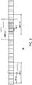
- Fig. 2 is a view illustrating a concept of estimating a selected section of other stations according to the first embodiment of the present disclosure. Each box illustrated in Fig. 2 may indicate a slot.
- the TDMA communication device 10 may include an antenna 100, a receiver 20, an estimating information acquirer 31, and a selected section estimator 32.
- the device may divide a frame comprised of a given time length into a plurality of slots, and after one frame is finished, the frame may transit to the next frame.
- Each station may reserve a transmission per slot, and transmit communication data by using the reserved slot as a transmission slot.
- the receiver 20 may perform a reception processing to a communication signal (communication data) received by the antenna 100, and then output it to the estimating information acquirer 31.
- the reception processing may include, for example, filtering, amplifying, and demodulating.
- the receiver 20 may output the demodulated communication data to the estimating information acquirer 31.
- the estimating information acquirer 31 may acquire estimation information related to transmission of a transmission source (another station) from the communication data. For example, the estimating information acquirer 31 may acquire, as estimation information, the position of a reception slot (position of the reception slot on a timeline) from a reception time of the communication data. The estimating information acquirer 31 may acquire the position of the reception slot each time it receives the communication data.
- the estimating information acquirer 31 may calculate estimation information based on the communication data. For example, the estimating information acquirer 31 calculates, as the estimation information, a transmission rate based on an interval of receiving the communication data, i.e., an interval of the reception slot. Moreover, the estimating information acquirer 31 may calculate the transmission rate based on a ship speed, if the ship speed is contained in the communication data. The transmission rate may correspond to a time interval NI of the selected section illustrated in Fig. 2 .
- the estimating information acquirer 31 may calculate a time interval NI defined by the system (corresponding to a "given time interval" of the present disclosure), and a time length of a selected section SI, based on the transmission rate.
- the estimating information acquirer 31 may calculate the time interval NI based on the transmission rate if the transmission rate can be calculated.
- the estimating information acquirer 31 may calculate a time length of the prescribed selected section SI based on the calculated time interval NI.
- the estimating information acquirer 31 may utilize a relation between the time interval NI and the time length of the selected section SI, which are defined by the system. For example, in the AIS, since the time length of the selected section SI may be defined as 0.2 times the time interval NI, the estimating information acquirer 31 may calculate the time length of the prescribed selected section SI by using the relation.
- the estimating information acquirer 31 may output the time interval NI, the time length of the selected section SI, and the position of the reception slot on the timeline (position of the reception slot) of another station, to the selected section estimator 32.
- the time interval NI, the time length of the selected section SI, and the position of the reception slot of another station may correspond to "estimation information of the selected section of another station" of the present disclosure.
- the selected section estimator 32 may set an estimated selected section of the transmission slots of another station based on the positions of the reception slots for two or more times, the time interval NI of another station, and the time length of the selected section SI. For example, the selected section estimator 32 may set an estimated selected section of the transmission slots of another station by using the concept illustrated in Fig. 2 .
- the selected section estimator 32 may determine a station (specific one among other stations) which will be a target for estimation of the selected section of transmission slots.
- the selected section estimator 32 may acquire, for the specific station, the position of a first reception slot Sr(1) and the position of a second reception slot Sr(2) which are adjacent to each other on the timeline.
- the first reception slot Sr(1) and the second reception slot Sr(2) may be lined up from old side.
- the position of the first reception slot Sr(1) may correspond to the "position of a first slot" of the present disclosure.
- the position of the second reception slot Sr(2) may correspond to the "position of a second slot" of the present disclosure.
- the selected section estimator 32 may set an estimated selected section SIE for the first reception slot (1) based on the first reception slot position Sr(1) and the time length of the selected section SI. For example, the selected section estimator 32 may set a temporary slot selected section SIE(12) which is assumed on the basis of the first reception slot position Sr(1) being the first slot of the selected section SI. This temporary slot selected section SIE(12) may correspond to a "first temporary slot selected section" of the present disclosure. The selected section estimator 32 may set a temporary slot selected section SIE(11) which is assumed on the basis of the first reception slot position Sr(1) being the last slot of the selected section SI. This temporary slot selected section SIE(11) may correspond to a "second temporary slot selected section" of the present disclosure.
- the selected section estimator 32 may set a range of slots which belong to at least one of the temporary slot selected section SIE(11) and the temporary slot selected section SIE(12) as an estimated maximum selected section SIE(1) for the first reception slot.
- the first reception slot may be the center slot, and the time length of the estimated maximum selected section SIE(1) may be longer than the time length of the prescribed selected section SI.
- the selected section estimator 32 may retard the estimated maximum selected section SIE(1) for the first reception slot by the time interval NI on the timeline to set a first temporary estimation selected section SIPE'(2).
- the selected section estimator 32 may set a second temporary estimation selected section SIPE(2) based on the position Sr(2) of the second reception slot and the time length of the selected section SI. For example, the selected section estimator 32 may set a temporary slot selected section SIPE(22) which is assumed on the basis of the second reception slot position Sr(2) being the first slot of the selected section SI. This temporary slot selected section SIPE(22) may correspond to a "third temporary slot selected section" of the present disclosure. The selected section estimator 32 may set a temporary slot selected section SIPE(21) which is assumed on the basis of the second reception slot position Sr(2) being the last slot of the selected section SI. This temporary slot selected section SIPE(21) may correspond to a "fourth temporary slot selected section" of the present disclosure.
- the selected section estimator 32 may set a range of slots which belong to at least one of the temporary slot selected section SIPE(21) and the temporary slot selected section SIPE(22) as the second temporary estimation selected section SIPE(2).
- the second reception slot may be the center slot, and the time length of the second temporary estimation selected section SIPE(2) may be longer than the time length of the prescribed selected section SI.
- the selected section estimator 32 may set the slots where the first temporary estimation selected section SIPE'(2) and the second temporary estimation selected section SIPE(2) overlap with each other (obliquely-hatched slots in Fig. 2 ) as the estimated selected section SIE(2) of another station.
- the estimated selected section of the transmission slots of the specific station may be estimated easily and certainly based on the positions of the reception slots of the specific station which are adjacent to each other on the timeline, the prescribed time interval NI, and the time length of the prescribed selected section SI.
- the setting of the estimated selected section of the transmission slot may be performed to each communication data which is received from each station, in other words, to each station which performs communication.
- the plurality of reception slots used for the setting of the estimated selected section may not be adjacent to each other on the timeline. That is, two reception slots having one or more reception slots therebetween on the timeline may be selected.
- the retarding amount may be set by multiplying the time interval NI by an integer, according to the time difference between the two selected reception slots.
- a flowchart illustrated in Fig. 3 may be used.
- Fig. 3 is the flowchart for setting the estimated selected section in the TDMA communication method according to the first embodiment of the present disclosure.
- the processor may detect the first reception slot position Sr(1) (S101).
- the processor may acquire the time interval NI and the time length of selected section SI defined by the system from the received communication data, using the method described above (S102).
- the processor may set the estimated maximum selected section SIE(1) for the first reception slot from the first reception slot position Sr(1) and the time length of the selected section SI, using the method described above (S103).
- the processor may detect the second reception slot position Sr(2) on the timeline (S104).
- the processor may set the second temporary estimation selected section SIPE(2) from the second reception slot position Sr(2) and the time length of the selected section SI, using the method described above (S105).
- the processor may set the first temporary estimation selected section SIPE'(2) from the estimated maximum selected section SIE(1) and the time interval NI for the first reception slot, using the method described above (S106). Note that the setting of the second temporary estimation selected section SIPE(2) and the setting of the first temporary estimation selected section SIPE'(2) may be executed in this order or may be in the reversed order, or may be simultaneously executed in parallel.
- the processor may set the overlapped section of the second temporary estimation selected section SIPE(2) and the first temporary estimation selected section SIPE'(2) as the estimated selected section SIE(2) (S107).
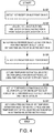
- Fig. 4 is another flowchart for estimating the selected section in the TDMA communication method according to the first embodiment of the present disclosure. Note that Steps S101, S102, and S103 are the same as those in the flowchart of Fig. 3 and, thus, description thereof is omitted.
- the processor may detect the position Sr(k) of the k-th reception slot (S142).
- the processor may set the second temporary estimation selected section SIPE(k) for the k-th reception slot from the position Sr(k) of the k-th reception slot and the time length of the selected section SI, using the method described above (S143).
- the processor may set the first temporary estimation selected section SIPE'(k) for the k-th reception slot from the estimated selected section SIE(k-1) for the k-1th reception slot and the time interval NI, using the method described above (S144).
- the estimated maximum selected section SIE(1) may be used, and if k>3, the last estimated selected section SIE(k-1) may be used.
- the setting of the first temporary estimation selected section SIPE'(k) and the setting of the second temporary estimation selected section SIPE(k) may be executed in this order or may be in the reversed order, or may be simultaneously executed in parallel.
- the processor may set the overlapped section of the first temporary estimation selected section SIPE'(k) and the second temporary estimation selected section SIPE(k) as the estimated selected section SIE(k) (S145).
- the processor may use the time length of the estimated selected section SIE(k-1) which is set based on the overlapped section obtained from the last processing, for setting the first estimation selected section SIPE'(k) of Step S144.
- the overlapped section of the first temporary estimation selected section SIPE'(2) obtained from the first reception slot, and the second temporary estimation selected section SIPE(2) obtained from the second reception slot may be used, as described above.
- the overlapped section of the first temporary estimation selected section SIPE'(3) which is obtained by retarding the estimated selected section SIE(2) for the second reception slot by the time interval NI, and the second temporary estimation selected section SIPE(3) which is obtained from the third reception slot and the time length of the selected section SI may be used. That is, the overlapped section may be calculated using the second temporary estimation selected section SIPE(3) calculated based on the position of the third reception slot and the last estimated selected section. Thereafter, similar processing for detecting the overlapped section may be repeated to update the overlapped section.
- the last estimated selected section is not limited to one using the last reception slot of the third reception slot, but may use at least one of a plurality of estimated selected sections SIE obtained earlier.
- the retarding time of the estimated selected section may be set according to a time difference between the time of the estimated selected section used for this processing and the time of the third reception slot.
- the retarding time may be set based on the time interval NI.
- the end condition may be set, for example, when k becomes a given value, or when the number of times that the time length of the estimated selected section SIE(k) does not become shorter than the time length of the estimated selected section SIE(k-1) reaches a given number of times.
- the setting of the end condition is not limited to the above configuration, but the end condition may suitably be set according to the accuracy and rate of the estimation of the estimated selected section SIE(k).
- the estimated selected section may be initialized and the processing described above may be executed using the new time interval NI and the time length of the selected section SI.
- the processor may use the set estimated selected section SIE(k) (S147).
- the estimated selected section SIE(k) can be approximated having the true selected section SI of another station as the minimum range. Therefore, the estimation accuracy of the estimated selected section SIE(k) may improve.
- Fig. 5 is a functional block diagram of the TDMA communication device according to the second embodiment of the present disclosure.
- the TDMA communication device 10A according to this embodiment may be configured by adding a transmission controller 50 to the TDMA communication device 10 according to the first embodiment. Moreover, it may be provided with a transmitter/receiver 40, instead of the receiver 20.
- the estimated selected section SIE of another station which is set by the selected section estimator 32 may be inputted into the transmission controller 50.
- the transmission controller 50 may detect the possibility of a collision of the transmission slot of the local station and the transmission slot of another station based on a spatial relationship on the timeline between the estimated selected section SIE of another station and the selected section of the local station.
- the transmission controller 50 may set the transmission slot of the local station so as to avoid the collision with the transmission slot of another station.
- the transmission controller 50 may transmit the communication data (communication signal) of the local station to another station through the transmitter/receiver 40 and the antenna 100, by using the set transmission slot.
- Figs. 6(A) and 6(B) are views illustrating the concept of the detection method of the possibility of the collision and the collision avoiding method according to the second embodiment of the present disclosure.
- Fig. 6(A) illustrates a case where other stations include a single station
- Fig. 6(B) illustrates a case where other stations include two stations.
- NIs is a time interval of the selected section SIs of the local station.
- a selected section SIs(j) is determined based on the last selected section SIs(j-1) and the time interval NIs.
- the transmission controller 50 may detect the existence of overlapping with the selected section SIs(j) of the local station. The transmission controller 50 may set the next transmission slot from the slots within the selected section SIs(j) of the local station, which do not currently overlap with the estimated selected section SIE of another station, as a preprocessing of transmission by the local station.
- the estimated selected section SIEa(i) of another station and the selected section SIs(j) of the local station may overlap by two slots (an overlapped section OL(j)), and other slots of the selected section SIs(j) of the local station may not overlap (a non-overlapped section NOL(j)).
- the transmission controller 50 may select one slot from the non-overlapped section NOL(j) in the selected section SIs(j), and set it as the transmission slot. Therefore, the transmission slot of the local station may be prevented from overlapping with the transmission slot of another station.
- the selected section Sis(j) of the local station may include an overlapped section OL1(j) of the estimated selected section SIEa1(i) of another station (station 1) and the selected section SIs(j) of the local station, an overlapped section OL2(j) of an estimated selected section SIEa2(k) of another station (station 2) and the selected section SIs(j) of the local station, and a non-overlapped section NOL(j) which does not overlap with any of them.
- the transmission controller 50 may select one slot from the non-overlapped section NOL(j) within the selected section SIs(j), and set it as a transmission slot. Therefore, the transmission slot of the local station may be prevented from overlapping with the transmission slots of other stations.
- the transmission controller 50 may calculate a collision probability Cp over each slot within the selected section SIs(j) of the local station.
- the probability that the slot of the selected section SIs(j) of the local station overlaps with the estimated selected sections SIE of other stations, and this slot is selected as the transmission slot of another station is 1/Na, if the number of slots of the estimated selected sections SIE of other stations is Na.
- the probability that one slot within the selected section SIs(j) of the local station is selected as the transmission slot by all the other stations where the estimated selected sections SIE overlap is referred to as the collision probability Cp, and it is calculated by the following equation.
- Cp 1 ⁇ ⁇ Na i ⁇ 1 / Na i Na(i) is the number of slots of the estimated selected section SIE(i) of another station i which overlap with the selected section SIs of the local station.
- the transmission controller 50 may calculate the collision probability Cp for each slot within the selected section SIs of the local station, which overlaps with the estimated selected sections SIE of other stations, by using Equation 1.
- the transmission controller 50 may calculate the collision probability Cp for each slot of the selected section SIs of the local station.
- the collision probability Cp may decrease as the possibility of colliding with the transmission slots of another station is reduced, and increase as the possibility of colliding with the transmission slots of another station is increased. Therefore, the transmission controller 50 may set the slot having the lowest collision probability Cp as the transmission slot of the local station. More practically, the transmission controller 50 may select a plurality of slots with lower probabilities of collision Cp, and set the transmission slot among the slots.
- This selection may be utilized in a mode in which, for example, a threshold is provided for the collision probability Cp, and selects a plurality of slots with the probabilities of collision Cp below the threshold, or a mode in which the probabilities of collision Cp are sorted in a descending order, and a given number (a plurality of) slots with lower probabilities are selected. Therefore, the collision of the transmission slot with other stations can be prevented.
- a logarithm likelihood value obtained by adding a logarithmic value of the probability for each of other stations may be used instead of the collision probability Cp of Equation 1. Therefore, the possibility of collision of each slot of the local station with the transmission slots of other stations may be compared with a simpler calculation. Therefore, for example, a reduction of resources of the transmission controller 50 and a speed-up of the selection of the transmission slot of the local station can be achieved.
- Figs. 7 and 8 are flowcharts illustrated in Figs. 7 and 8.
- Fig. 7 is a flowchart for selecting the transmission slot in the TDMA communication method according to the second embodiment of the present disclosure.
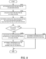
- Fig. 8 is a flowchart for calculating the collision probability in the TDMA communication method according to the second embodiment of the present disclosure.
- the processor may set the estimated selected section SIE of another station (S201). Note that the method according to the first embodiment (refer to Figs. 3 and 4 ) may be used for the setting of the estimated selected section SIE of another station.
- the processor may calculate the selected section SIs of the local station based on the initial center slot NSS and the time interval NIs (S202).
- the processor may determine the overlap of the selected section SIs of the local station with the estimated selected section SIE of another station (S203). If there are any non-overlapped sections (S204: NO), the processor may select the non-overlapped slots as the transmission slot (S207).
- the processor may calculate the collision probability Cp of each slot of the selected section SIs of the local station (S205). For example, as illustrated in Fig. 8 , the processor may acquire, for every slot of the selected section SIs of the local station, the number of slots Na of the estimated selected section SIE of another station, which overlap with the slot concerned (S301). The processor may calculate the collision probability Cp by using Equation 1 described above based on the number of all the slots Na(i) of the estimated selected section SIE of other stations i which overlap (S302). Note that, in this case, the logarithm likelihood value may also be used for the collision probability Cp.
- the processor may determine the transmission slot of the local station based on the probabilities of collision Cp (S206).
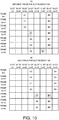
- Fig. 9 is a view illustrating a concept of a slot reservation of SOTDMA used by the AIS.
- Fig. 9(A) illustrates a case where other stations A and B have different frames for slot reservation
- Fig. 9(B) illustrates a case where other stations A and B have the same frame for slot reservation.
- a timeout value when reserving the transmission slot, a timeout value may be set.
- the same slot of a future frame may be temporarily reserved according to the number of frames corresponding to the timeout value. For example, as illustrated in Fig. 9(A) , when the station A sets the timeout value "7" in a frame (m+3) and reserves a slot (n+3), the slot (n+3) may be temporarily reserved for seven frames at and after a frame (m+4). At and after the frame (m+4), the station A may reserve the slot (n+3) while subtracting the timeout value "1" for every frame. Then, the station A may select the position of the transmission slot in the next frame when the timeout value becomes "0.”
- the station B may watch the reservation status of the station A, and reserve the transmission slot so as not to collide with the station A. For example, in a frame (m+6), since the reservation of the slot (n+3) by the station A is continuing, the station B reserves a slot (n+5) while excluding the slot (n+3).
- the mode in which, when the transmission slot reservation information of other stations is not available, the selected sections of the transmission slots of other stations may be estimated is illustrated. However, if the transmission slot reservation information of other stations is available, the selected sections of the transmission slots of other stations may be estimated based on the transmission slot reservation information.
- the TDMA communication device 10 may execute the following processing.
- the receiver 20 may perform reception processing for the communication signal (communication data) received by the antenna 100, and output it to the estimating information acquirer 31.
- the reception processing is, for example, filtering, amplifying, and demodulating.
- the communication data may include the slot reservation information of other stations (transmission-source stations), and the slot reservation information of other stations can be acquired by demodulating the communication data.
- the slot reservation information may include the positions (positions on the timeline) of the reservation slots of other stations.
- the estimating information acquirer 31 may detect the position of the reservation slot from the slot reservation information.
- the estimating information acquirer 31 may temporally repeat the detection of the position of the reservation slot.
- the estimating information acquirer 31 may calculate the prescribed time interval NI based on the time interval of two reservation slots at different times.
- Other processings of the estimating information acquirer 31 may be the same as the processing described in the first embodiment, but the position of the reception slot may be replaced with the position of the reservation slot.
- the selected section estimator 32 may estimate the selected section of the transmission slots of another station by using the positions of the reservation slots for a plurality of times, the time interval NI of another station, and the time length of the selected section SI.
- the estimation of the selected section of the transmission slots of another station may be realized by replacing the position of the reception slot in the first embodiment with the position of the reservation slot.
- the selected sections of the transmission slots of other stations may be estimated easily and certainly.
- the detailed communication status of other stations may be grasped.
- the selected section of the transmission slots, and the time interval of the selected section may depend on the moving speed of the station (ship etc.).
- each station may generally change the communication status according to the moving speed. Therefore, the detailed communication status of other stations may be grasped by estimating the selected section.
- this configuration using the reservation slot is also applicable to the TDMA communication device 10A according to the second embodiment.
- the reception slot may be replaced with the reservation slot. Therefore, the same operation and effects as the TDMA communication method described in each embodiment may be acquired.
Landscapes
- Engineering & Computer Science (AREA)
- Computer Networks & Wireless Communication (AREA)
- Signal Processing (AREA)
- Time-Division Multiplex Systems (AREA)
- Mobile Radio Communication Systems (AREA)
Abstract
Description
- The present disclosure relates to a TDMA communication device and a TDMA communication method in which a plurality of stations mutually reserve a slot through which a transmission is to be performed, and each station transmits communication data using the reserved slot.
- In a TDMA communication system, one frame comprised of a preset time length is time divided to or shared by a plurality of slots. Each station which performs TDMA communications transmits and receives communication data per slot. In the TDMA communication system, various kinds of detailed protocols are defined according to the system, and for example, in the AIS (Automatic Identification System) using SOTDMA communication systems disclosed in
Patent Documents -
Fig. 10 is a view illustrating protocol to determine a transmission slot defined by the AIS. Each box illustrated inFig. 10 indicates a slot. As illustrated inFig. 10 , the frame is comprised of a plurality of slots arranged in a time series. - As illustrated in
Fig. 10 , in order to transmit at a substantially constant cycle, a station which transmits in the TDMA communication system sets a selected section SI of transmission slots St at a constant time interval NI. For example, the selected section SI is comprised of a given number of continuous slots. A center slot NS of the selected section SI is set at the constant time interval NI. Note that, as illustrated inFig. 10 , the center slot NS of the selected section for the first time is referred to as "NSS," which is set when booting a TDMA communication device. In the selected section SI including the first-time center slot NSS, the station selects one of the plurality of slots which constitute the selected section SI as a transmission slot St, and then transmits the communication data through the transmission slot St. - Here, the station also determines the position of the transmission slot St in the next selected section SI, and transmits the communication data along with the determined position (a reservation of the transmission slot). In subsequent selected sections SI, the station similarly transmits the communication data in the transmission slot St along with the slot reservation information containing the position of the next transmission slot. Thus, by notifying the position of the transmission slot for the next time of one local station to other stations, a collision of the transmission slot of the local station with the transmission slot of other stations is avoided.
-
- [Patent Document 1]
JP4486483B2 - [Patent Document 2]
JP4014517B2 - However, in the TDMA communication system, when the local station determines the position of the next transmission slot, it may not be able to use the slot reservation information from other stations. For example, simply, the local station may not be able to receive the slot reservation information from other stations. Even if the local station is able to receive the slot reservation information from other stations, processing to reflect the information on a slot map may be delayed, thereby becoming too late for the local station setting up the position of the transmission slot.
- When the slot reservation information of other stations cannot be used as described above, the following problems may arise.
Fig. 11 is a view illustrating the problems of the TDMA communication system of the conventional art.Fig. 11 illustrates a selected state of transmission slots of the local station (s) and another station (a). InFig. 11 , SIs indicates a selected section of the local station (s), and NSs indicates a center slot of the selected section SIs. SIa indicates a selected section of another station (a), and NSa indicates a center slot of the selected section SIa. - As illustrated in
Fig. 11 , in a situation where the local station (s) and another station (a) transmit through the same frame, depending on a time interval NIs of the local station (s), a time interval NIa of another station (a), and a spatial relationship between the last transmission slot of the local station (s) and the last transmission slot of another station (a), the selected section SIs of the local station (s) and the selected section SIa of another station (a) which are to be used for the current reservation may be at least partially overlapped with each other. - If such an overlapped section exists, the transmission slot of the local station (s) and the transmission slot of another station (a) may collide (overlap) when the transmission slot is set within the overlapped section.
- Moreover, when grasping the detailed communication status of other stations, communication data related to the communication status must be frequently transmitted from other stations.
- However, when the detailed communication status is transmitted as described above, the frequency of using the slot per station simply increases, and thereby the transmission slot becomes easier to collide by a plurality of stations (for example, other stations and the local station). Here, for example, by the AIS, the selected section of the transmission slots and the time interval of the selected section depend on a moving speed of the station (e.g., a ship). Each station generally changes the communication status according to the moving speed. Thus, it may be possible to grasp the detailed communication status of other stations by estimating the selected sections of the transmission slots of other stations. This would be the same regardless of the situation if the slot reservation information of other stations are or are not available.
- Therefore, one purpose of the present disclosure is to provide a TDMA communication device and a TDMA communication method, which estimate a selected section of transmission slots of other stations.
- A TDMA communication device according to this disclosure may include a receiver, an estimating information acquirer, and a selected section estimator. The receiver may receive communication data from another station through any of a plurality of reception slots within a selected section set based on a given time interval. The estimating information acquirer may acquire and calculate estimation information for an estimated selected section of another station based on the communication data received from another station. The selected section estimator may set the estimated selected section based on the estimation information.
- According to this configuration, based on the communication data received from another station, the estimation information according to a selected section of transmission slots of other stations can be obtained.
- According to the present disclosure, in the TDMA communication system, the selected section of the transmission slots of other stations may be estimated.
-
-
Fig. 1 is a functional block diagram of a TDMA communication device according to a first embodiment of the present disclosure. -
Fig. 2 is a view illustrating a concept of estimating a selected section according to the first embodiment of the present disclosure. -
Fig. 3 is a flowchart for setting the estimated selected section in a TDMA communication method according to the first embodiment of the present disclosure. -
Fig. 4 is another flowchart for setting the estimated selected section in the TDMA communication method according to the first embodiment of the present disclosure. -
Fig. 5 is a functional block diagram of a TDMA communication device according to a second embodiment of the present disclosure. -
Fig. 6 is a view illustrating a concept of a detection method of the possibility of a collision and a collision avoiding method, according to the second embodiment of the present disclosure. -
Fig. 7 is a flowchart for selecting a transmission slot in a TDMA communication method according to the second embodiment of the present disclosure. -
Fig. 8 is a flowchart for calculating the probability of the collision in the TDMA communication method according to the second embodiment of the present disclosure. -
Fig. 9 is a view illustrating a concept of a slot reservation of SOTDMA used by AIS. -
Fig. 10 is a view illustrating a protocol for determining the transmission slot defined by the AIS. -
Fig. 11 is a view illustrating problems in a TDMA communication method disclosed in a conventional art. - A TDMA communication device and a TDMA communication method according to a first embodiment of the present disclosure will be described with reference to the drawings. Note that, although a case of TDMA communications used by AIS for ships is illustrated below, a configuration of this embodiment is also applicable to other TDMA communications using the same reservation system of transmission slots.
Fig. 1 is a functional block diagram of the TDMA communication device according to the first embodiment of the present disclosure.Fig. 2 is a view illustrating a concept of estimating a selected section of other stations according to the first embodiment of the present disclosure. Each box illustrated inFig. 2 may indicate a slot. - The
TDMA communication device 10 may include anantenna 100, areceiver 20, an estimating information acquirer 31, and aselected section estimator 32. In TDMA (time division multiple access) communications used by theTDMA communication device 10, the device may divide a frame comprised of a given time length into a plurality of slots, and after one frame is finished, the frame may transit to the next frame. Each station may reserve a transmission per slot, and transmit communication data by using the reserved slot as a transmission slot. - The
receiver 20 may perform a reception processing to a communication signal (communication data) received by theantenna 100, and then output it to the estimatinginformation acquirer 31. The reception processing may include, for example, filtering, amplifying, and demodulating. Thereceiver 20 may output the demodulated communication data to the estimatinginformation acquirer 31. - The estimating
information acquirer 31 may acquire estimation information related to transmission of a transmission source (another station) from the communication data. For example, the estimatinginformation acquirer 31 may acquire, as estimation information, the position of a reception slot (position of the reception slot on a timeline) from a reception time of the communication data. The estimatinginformation acquirer 31 may acquire the position of the reception slot each time it receives the communication data. - Moreover, the estimating
information acquirer 31 may calculate estimation information based on the communication data. For example, the estimatinginformation acquirer 31 calculates, as the estimation information, a transmission rate based on an interval of receiving the communication data, i.e., an interval of the reception slot. Moreover, the estimatinginformation acquirer 31 may calculate the transmission rate based on a ship speed, if the ship speed is contained in the communication data. The transmission rate may correspond to a time interval NI of the selected section illustrated inFig. 2 . - The estimating
information acquirer 31 may calculate a time interval NI defined by the system (corresponding to a "given time interval" of the present disclosure), and a time length of a selected section SI, based on the transmission rate. The estimatinginformation acquirer 31 may calculate the time interval NI based on the transmission rate if the transmission rate can be calculated. The estimatinginformation acquirer 31 may calculate a time length of the prescribed selected section SI based on the calculated time interval NI. Here, the estimatinginformation acquirer 31 may utilize a relation between the time interval NI and the time length of the selected section SI, which are defined by the system. For example, in the AIS, since the time length of the selected section SI may be defined as 0.2 times the time interval NI, the estimatinginformation acquirer 31 may calculate the time length of the prescribed selected section SI by using the relation. - The estimating
information acquirer 31 may output the time interval NI, the time length of the selected section SI, and the position of the reception slot on the timeline (position of the reception slot) of another station, to the selectedsection estimator 32. The time interval NI, the time length of the selected section SI, and the position of the reception slot of another station may correspond to "estimation information of the selected section of another station" of the present disclosure. - The selected
section estimator 32 may set an estimated selected section of the transmission slots of another station based on the positions of the reception slots for two or more times, the time interval NI of another station, and the time length of the selected section SI. For example, the selectedsection estimator 32 may set an estimated selected section of the transmission slots of another station by using the concept illustrated inFig. 2 . - The selected
section estimator 32 may determine a station (specific one among other stations) which will be a target for estimation of the selected section of transmission slots. The selectedsection estimator 32 may acquire, for the specific station, the position of a first reception slot Sr(1) and the position of a second reception slot Sr(2) which are adjacent to each other on the timeline. Here, on the timeline, the first reception slot Sr(1) and the second reception slot Sr(2) may be lined up from old side. The position of the first reception slot Sr(1) may correspond to the "position of a first slot" of the present disclosure. The position of the second reception slot Sr(2) may correspond to the "position of a second slot" of the present disclosure. - The selected
section estimator 32 may set an estimated selected section SIE for the first reception slot (1) based on the first reception slot position Sr(1) and the time length of the selected section SI. For example, the selectedsection estimator 32 may set a temporary slot selected section SIE(12) which is assumed on the basis of the first reception slot position Sr(1) being the first slot of the selected section SI. This temporary slot selected section SIE(12) may correspond to a "first temporary slot selected section" of the present disclosure. The selectedsection estimator 32 may set a temporary slot selected section SIE(11) which is assumed on the basis of the first reception slot position Sr(1) being the last slot of the selected section SI. This temporary slot selected section SIE(11) may correspond to a "second temporary slot selected section" of the present disclosure. - The selected
section estimator 32 may set a range of slots which belong to at least one of the temporary slot selected section SIE(11) and the temporary slot selected section SIE(12) as an estimated maximum selected section SIE(1) for the first reception slot. Thus, in the estimated maximum selected section SIE(1), the first reception slot may be the center slot, and the time length of the estimated maximum selected section SIE(1) may be longer than the time length of the prescribed selected section SI. - The selected
section estimator 32 may retard the estimated maximum selected section SIE(1) for the first reception slot by the time interval NI on the timeline to set a first temporary estimation selected section SIPE'(2). - The selected
section estimator 32 may set a second temporary estimation selected section SIPE(2) based on the position Sr(2) of the second reception slot and the time length of the selected section SI. For example, the selectedsection estimator 32 may set a temporary slot selected section SIPE(22) which is assumed on the basis of the second reception slot position Sr(2) being the first slot of the selected section SI. This temporary slot selected section SIPE(22) may correspond to a "third temporary slot selected section" of the present disclosure. The selectedsection estimator 32 may set a temporary slot selected section SIPE(21) which is assumed on the basis of the second reception slot position Sr(2) being the last slot of the selected section SI. This temporary slot selected section SIPE(21) may correspond to a "fourth temporary slot selected section" of the present disclosure. - The selected
section estimator 32 may set a range of slots which belong to at least one of the temporary slot selected section SIPE(21) and the temporary slot selected section SIPE(22) as the second temporary estimation selected section SIPE(2). Thus, in the second temporary estimation selected section SIPE(2), the second reception slot may be the center slot, and the time length of the second temporary estimation selected section SIPE(2) may be longer than the time length of the prescribed selected section SI. - The selected
section estimator 32 may set the slots where the first temporary estimation selected section SIPE'(2) and the second temporary estimation selected section SIPE(2) overlap with each other (obliquely-hatched slots inFig. 2 ) as the estimated selected section SIE(2) of another station. - Thus, by using the configuration of this embodiment, the estimated selected section of the transmission slots of the specific station may be estimated easily and certainly based on the positions of the reception slots of the specific station which are adjacent to each other on the timeline, the prescribed time interval NI, and the time length of the prescribed selected section SI. Note that the setting of the estimated selected section of the transmission slot may be performed to each communication data which is received from each station, in other words, to each station which performs communication.
- Note that the plurality of reception slots used for the setting of the estimated selected section may not be adjacent to each other on the timeline. That is, two reception slots having one or more reception slots therebetween on the timeline may be selected. In this case, the retarding amount may be set by multiplying the time interval NI by an integer, according to the time difference between the two selected reception slots.
- Although in the above description the mode in which the setting of the estimated selected section of the transmission slots of other stations is executed by the plurality of functional parts, each comprised of hardware such as the IC, is illustrated, the setting processing of the estimated selected section of the transmission slots may be programmed and stored in a memory etc., and this program may be executed by a processor, such as a computer or a CPU. In this case, a flowchart illustrated in
Fig. 3 may be used.Fig. 3 is the flowchart for setting the estimated selected section in the TDMA communication method according to the first embodiment of the present disclosure. - The processor may detect the first reception slot position Sr(1) (S101). The processor may acquire the time interval NI and the time length of selected section SI defined by the system from the received communication data, using the method described above (S102). The processor may set the estimated maximum selected section SIE(1) for the first reception slot from the first reception slot position Sr(1) and the time length of the selected section SI, using the method described above (S103).
- The processor may detect the second reception slot position Sr(2) on the timeline (S104). The processor may set the second temporary estimation selected section SIPE(2) from the second reception slot position Sr(2) and the time length of the selected section SI, using the method described above (S105).
- The processor may set the first temporary estimation selected section SIPE'(2) from the estimated maximum selected section SIE(1) and the time interval NI for the first reception slot, using the method described above (S106). Note that the setting of the second temporary estimation selected section SIPE(2) and the setting of the first temporary estimation selected section SIPE'(2) may be executed in this order or may be in the reversed order, or may be simultaneously executed in parallel.
- The processor may set the overlapped section of the second temporary estimation selected section SIPE(2) and the first temporary estimation selected section SIPE'(2) as the estimated selected section SIE(2) (S107).
- Note that in the above description the mode in which the estimated selected section is set by the one-time detection of the overlapped section is illustrated. As illustrated below, the detection of the overlapped section may be repeated and updated to make the estimated selected section SIE approach a true selected section SI of another station.
Fig. 4 is another flowchart for estimating the selected section in the TDMA communication method according to the first embodiment of the present disclosure. Note that Steps S101, S102, and S103 are the same as those in the flowchart ofFig. 3 and, thus, description thereof is omitted. - The processor may set k=2 after processing of Step S103 (S141).
- The processor may detect the position Sr(k) of the k-th reception slot (S142). The processor may set the second temporary estimation selected section SIPE(k) for the k-th reception slot from the position Sr(k) of the k-th reception slot and the time length of the selected section SI, using the method described above (S143).
- The processor may set the first temporary estimation selected section SIPE'(k) for the k-th reception slot from the estimated selected section SIE(k-1) for the k-1th reception slot and the time interval NI, using the method described above (S144). Here, if k=2, the estimated maximum selected section SIE(1) may be used, and if k>3, the last estimated selected section SIE(k-1) may be used. Moreover, the setting of the first temporary estimation selected section SIPE'(k) and the setting of the second temporary estimation selected section SIPE(k) may be executed in this order or may be in the reversed order, or may be simultaneously executed in parallel.
- The processor may set the overlapped section of the first temporary estimation selected section SIPE'(k) and the second temporary estimation selected section SIPE(k) as the estimated selected section SIE(k) (S145).
- If an end condition of the setting of the estimated selected section is not satisfied (S146: NO), the processor may execute processing of k=k+1 (S151), and return to Step S142.
- Thereafter, the processor may use the time length of the estimated selected section SIE(k-1) which is set based on the overlapped section obtained from the last processing, for setting the first estimation selected section SIPE'(k) of Step S144.
- For example, as for the estimated selected section SIE(2) of the second reception slot, the overlapped section of the first temporary estimation selected section SIPE'(2) obtained from the first reception slot, and the second temporary estimation selected section SIPE(2) obtained from the second reception slot, may be used, as described above. As for an estimated selected section SIE(3) of a third reception slot (this third reception slot corresponds to a "third slot" of the present disclosure), the overlapped section of the first temporary estimation selected section SIPE'(3) which is obtained by retarding the estimated selected section SIE(2) for the second reception slot by the time interval NI, and the second temporary estimation selected section SIPE(3) which is obtained from the third reception slot and the time length of the selected section SI, may be used. That is, the overlapped section may be calculated using the second temporary estimation selected section SIPE(3) calculated based on the position of the third reception slot and the last estimated selected section. Thereafter, similar processing for detecting the overlapped section may be repeated to update the overlapped section.
- Note that, the last estimated selected section is not limited to one using the last reception slot of the third reception slot, but may use at least one of a plurality of estimated selected sections SIE obtained earlier. In this case, the retarding time of the estimated selected section may be set according to a time difference between the time of the estimated selected section used for this processing and the time of the third reception slot. Here, the retarding time may be set based on the time interval NI.
- Here, the end condition may be set, for example, when k becomes a given value, or when the number of times that the time length of the estimated selected section SIE(k) does not become shorter than the time length of the estimated selected section SIE(k-1) reaches a given number of times. Note that the setting of the end condition is not limited to the above configuration, but the end condition may suitably be set according to the accuracy and rate of the estimation of the estimated selected section SIE(k).
- Note that although illustration is omitted, if the transmission rate (i.e., the time interval NI and the time length of the selected section SI) changes during the calculation of the estimated selected section SIE, the estimated selected section may be initialized and the processing described above may be executed using the new time interval NI and the time length of the selected section SI.
- If the end condition is satisfied (S146: YES), the processor may use the set estimated selected section SIE(k) (S147).
- By using such processing, unless all the temporal positions of the transmission slots in the selected section of another station (the temporal position of the reception slot for the local station) are the same, the estimated selected section SIE(k) can be approximated having the true selected section SI of another station as the minimum range. Therefore, the estimation accuracy of the estimated selected section SIE(k) may improve.
- Next, a TDMA communication device and a TDMA communication method according to a second embodiment of the present disclosure are described with reference to the drawings.
Fig. 5 is a functional block diagram of the TDMA communication device according to the second embodiment of the present disclosure. TheTDMA communication device 10A according to this embodiment may be configured by adding atransmission controller 50 to theTDMA communication device 10 according to the first embodiment. Moreover, it may be provided with a transmitter/receiver 40, instead of thereceiver 20. - The estimated selected section SIE of another station which is set by the selected
section estimator 32 may be inputted into thetransmission controller 50. Thetransmission controller 50 may detect the possibility of a collision of the transmission slot of the local station and the transmission slot of another station based on a spatial relationship on the timeline between the estimated selected section SIE of another station and the selected section of the local station. Thetransmission controller 50 may set the transmission slot of the local station so as to avoid the collision with the transmission slot of another station. Thetransmission controller 50 may transmit the communication data (communication signal) of the local station to another station through the transmitter/receiver 40 and theantenna 100, by using the set transmission slot. - Next, the detection method of the possibility of the collision and a collision avoiding method by the
TDMA communication device 10A are described in more detail.Figs. 6(A) and 6(B) are views illustrating the concept of the detection method of the possibility of the collision and the collision avoiding method according to the second embodiment of the present disclosure.Fig. 6(A) illustrates a case where other stations include a single station, andFig. 6(B) illustrates a case where other stations include two stations. Note that inFigs. 6(A) and 6(B) , NIs is a time interval of the selected section SIs of the local station. A selected section SIs(j) is determined based on the last selected section SIs(j-1) and the time interval NIs. - When an estimated selected section SIEa(i) of another station is acquired from the selected
section estimator 32, thetransmission controller 50 may detect the existence of overlapping with the selected section SIs(j) of the local station. Thetransmission controller 50 may set the next transmission slot from the slots within the selected section SIs(j) of the local station, which do not currently overlap with the estimated selected section SIE of another station, as a preprocessing of transmission by the local station. - In the case of
Fig. 6(A) , the estimated selected section SIEa(i) of another station and the selected section SIs(j) of the local station may overlap by two slots (an overlapped section OL(j)), and other slots of the selected section SIs(j) of the local station may not overlap (a non-overlapped section NOL(j)). - The
transmission controller 50 may select one slot from the non-overlapped section NOL(j) in the selected section SIs(j), and set it as the transmission slot. Therefore, the transmission slot of the local station may be prevented from overlapping with the transmission slot of another station. - In the case of
Fig. 6(B) , the selected section Sis(j) of the local station may include an overlapped section OL1(j) of the estimated selected section SIEa1(i) of another station (station 1) and the selected section SIs(j) of the local station, an overlapped section OL2(j) of an estimated selected section SIEa2(k) of another station (station 2) and the selected section SIs(j) of the local station, and a non-overlapped section NOL(j) which does not overlap with any of them. - The
transmission controller 50 may select one slot from the non-overlapped section NOL(j) within the selected section SIs(j), and set it as a transmission slot. Therefore, the transmission slot of the local station may be prevented from overlapping with the transmission slots of other stations. - If there is no non-overlapped section NOL, i.e., if all the slots of the selected section SIs(j) of the local station overlap with the estimated selected sections SIE of other stations, the
transmission controller 50 may calculate a collision probability Cp over each slot within the selected section SIs(j) of the local station. - Here, the probability that the slot of the selected section SIs(j) of the local station overlaps with the estimated selected sections SIE of other stations, and this slot is selected as the transmission slot of another station is 1/Na, if the number of slots of the estimated selected sections SIE of other stations is Na.
- Therefore, the probability that one slot within the selected section SIs(j) of the local station is selected as the transmission slot by all the other stations where the estimated selected sections SIE overlap is referred to as the collision probability Cp, and it is calculated by the following equation.

- The
transmission controller 50 may calculate the collision probability Cp for each slot within the selected section SIs of the local station, which overlaps with the estimated selected sections SIE of other stations, by usingEquation 1. - By performing such a calculation, the
transmission controller 50 may calculate the collision probability Cp for each slot of the selected section SIs of the local station. The collision probability Cp may decrease as the possibility of colliding with the transmission slots of another station is reduced, and increase as the possibility of colliding with the transmission slots of another station is increased. Therefore, thetransmission controller 50 may set the slot having the lowest collision probability Cp as the transmission slot of the local station. More practically, thetransmission controller 50 may select a plurality of slots with lower probabilities of collision Cp, and set the transmission slot among the slots. This selection may be utilized in a mode in which, for example, a threshold is provided for the collision probability Cp, and selects a plurality of slots with the probabilities of collision Cp below the threshold, or a mode in which the probabilities of collision Cp are sorted in a descending order, and a given number (a plurality of) slots with lower probabilities are selected. Therefore, the collision of the transmission slot with other stations can be prevented. - Note that a logarithm likelihood value obtained by adding a logarithmic value of the probability for each of other stations may be used instead of the collision probability Cp of
Equation 1. Therefore, the possibility of collision of each slot of the local station with the transmission slots of other stations may be compared with a simpler calculation. Therefore, for example, a reduction of resources of thetransmission controller 50 and a speed-up of the selection of the transmission slot of the local station can be achieved. - Note that in the above description the mode in which the detection of the possibility of the collision with the transmission slots of other stations is executed by the
transmission controller 50, and the estimation of the selected section of the transmission slots of other stations is executed by other functional parts. However, the estimation of the selected section of the transmission slots of other stations and the selection of the transmission slot of the local station may be programmed and stored in the memory etc., and the program may be executed by a processor, such as a computer or a CPU. In this case, flowcharts illustrated inFigs. 7 and8 may be used.Fig. 7 is a flowchart for selecting the transmission slot in the TDMA communication method according to the second embodiment of the present disclosure.Fig. 8 is a flowchart for calculating the collision probability in the TDMA communication method according to the second embodiment of the present disclosure. - As illustrated in
Fig. 7 , the processor may set the estimated selected section SIE of another station (S201). Note that the method according to the first embodiment (refer toFigs. 3 and4 ) may be used for the setting of the estimated selected section SIE of another station. - The processor may calculate the selected section SIs of the local station based on the initial center slot NSS and the time interval NIs (S202). The processor may determine the overlap of the selected section SIs of the local station with the estimated selected section SIE of another station (S203). If there are any non-overlapped sections (S204: NO), the processor may select the non-overlapped slots as the transmission slot (S207).
- If all the slots overlap, in other words, there is no non-overlapped section (S204: YES), the processor may calculate the collision probability Cp of each slot of the selected section SIs of the local station (S205). For example, as illustrated in
Fig. 8 , the processor may acquire, for every slot of the selected section SIs of the local station, the number of slots Na of the estimated selected section SIE of another station, which overlap with the slot concerned (S301). The processor may calculate the collision probability Cp by usingEquation 1 described above based on the number of all the slots Na(i) of the estimated selected section SIE of other stations i which overlap (S302). Note that, in this case, the logarithm likelihood value may also be used for the collision probability Cp. - The processor may determine the transmission slot of the local station based on the probabilities of collision Cp (S206).
- The estimation of the selected sections of other stations and the avoidance of the collision with the transmission slots of other stations may be utilized as follows by the AIS in the TDMA communication described above.
Fig. 9 is a view illustrating a concept of a slot reservation of SOTDMA used by the AIS.Fig. 9(A) illustrates a case where other stations A and B have different frames for slot reservation, andFig. 9(B) illustrates a case where other stations A and B have the same frame for slot reservation. - In the AIS, when reserving the transmission slot, a timeout value may be set. In the AIS, the same slot of a future frame may be temporarily reserved according to the number of frames corresponding to the timeout value. For example, as illustrated in
Fig. 9(A) , when the station A sets the timeout value "7" in a frame (m+3) and reserves a slot (n+3), the slot (n+3) may be temporarily reserved for seven frames at and after a frame (m+4). At and after the frame (m+4), the station A may reserve the slot (n+3) while subtracting the timeout value "1" for every frame. Then, the station A may select the position of the transmission slot in the next frame when the timeout value becomes "0." - In
Fig. 9(A) , the station B may watch the reservation status of the station A, and reserve the transmission slot so as not to collide with the station A. For example, in a frame (m+6), since the reservation of the slot (n+3) by the station A is continuing, the station B reserves a slot (n+5) while excluding the slot (n+3). - Thus, when the slots of a plurality of currently-communicating stations which have the timeout value becoming "0" are separated in time, since each station can grasp the reservation slot of other stations, collisions may be avoided.
- However, as illustrated in a frame (m+3) of
Fig. 9(B) , when the slot of the station A of which the timeout value is "0" and the slot of the station B of which the timeout value is "0" are close to each other in time, the stations A and B may be unable to mutually grasp the next reservation slots. In such a case, the possibility of the collision of the transmission slots may be prevented by estimating the selected section as described above. - Note that in the above description the mode in which, when the transmission slot reservation information of other stations is not available, the selected sections of the transmission slots of other stations may be estimated is illustrated. However, if the transmission slot reservation information of other stations is available, the selected sections of the transmission slots of other stations may be estimated based on the transmission slot reservation information.
- In this case, the
TDMA communication device 10 may execute the following processing. - The
receiver 20 may perform reception processing for the communication signal (communication data) received by theantenna 100, and output it to the estimatinginformation acquirer 31. The reception processing is, for example, filtering, amplifying, and demodulating. The communication data may include the slot reservation information of other stations (transmission-source stations), and the slot reservation information of other stations can be acquired by demodulating the communication data. The slot reservation information may include the positions (positions on the timeline) of the reservation slots of other stations. - The estimating
information acquirer 31 may detect the position of the reservation slot from the slot reservation information. The estimatinginformation acquirer 31 may temporally repeat the detection of the position of the reservation slot. The estimatinginformation acquirer 31 may calculate the prescribed time interval NI based on the time interval of two reservation slots at different times. Other processings of the estimatinginformation acquirer 31 may be the same as the processing described in the first embodiment, but the position of the reception slot may be replaced with the position of the reservation slot. - The selected
section estimator 32 may estimate the selected section of the transmission slots of another station by using the positions of the reservation slots for a plurality of times, the time interval NI of another station, and the time length of the selected section SI. The estimation of the selected section of the transmission slots of another station may be realized by replacing the position of the reception slot in the first embodiment with the position of the reservation slot. - Thus, even in a situation where the reservation slots of other stations are detectable, the selected sections of the transmission slots of other stations may be estimated easily and certainly.
- Moreover, by estimating the selected sections of the transmission slots of other stations as described above, the detailed communication status of other stations may be grasped. For example, in the AIS, the selected section of the transmission slots, and the time interval of the selected section may depend on the moving speed of the station (ship etc.). Moreover, each station may generally change the communication status according to the moving speed. Therefore, the detailed communication status of other stations may be grasped by estimating the selected section.
- Moreover, this configuration using the reservation slot is also applicable to the
TDMA communication device 10A according to the second embodiment. - Moreover, also in the TDMA communication method described in each embodiment, the reception slot may be replaced with the reservation slot. Therefore, the same operation and effects as the TDMA communication method described in each embodiment may be acquired.
-
- 10, 10A:
- TDMA Communication Device
- 20:
- Receiver
- 31:
- Estimating Information Acquirer
- 32:
- Selected Section Estimator
- 40:
- Transmitter/Receiver
- 50:
- Transmission Controller
- 100:
- Antenna
Claims (17)
- A TDMA communication device, comprising:a receiver configured to receive communication data from another station through any of a plurality of reception slots within a selected section set based on a given time interval;an estimating information acquirer configured to acquire and calculate estimation information for an estimated selected section of another station based on the communication data received from another station; anda selected section estimator configured to estimate the estimated selected section based on the estimation information.
- The TDMA communication device of claim 1, wherein the estimation information includes the selected section.
- The TDMA communication device of claim 1 or 2, wherein the estimation information includes the given time interval.
- The TDMA communication device of claim 2 or 3, wherein the selected section is calculated based on the given time interval.
- The TDMA communication device of any one of claims 1 to 4, wherein the estimation information includes positions of a first slot and a second slot of another station,
wherein each of the positions of the first slot and the second slot is a position of the reception slot through which the communication data is received, and
wherein the given time interval is calculated based on the positions of the first slot and the second slot. - The TDMA communication device of claim 4, wherein the given time interval is calculated based on an interval of reservation slots included in the communication data from another station.
- The TDMA communication device of claim 6, wherein the estimation information includes positions of a first slot and a second slot of another station,
wherein each of the positions of the first slot and the second slot is a position of a reservation slot through which the communication data is acquired, and
wherein the interval of the reservation slots is calculated based on the positions of the first slot and the second slot. - The TDMA communication device of claim 5 or 7, wherein the selected section estimator sets a first temporary estimation selected section based on the position of the first slot, the given time interval, and the selected section, sets a second temporary estimation selected section based on the position of the second slot and the selected section, and sets an overlapped section of the first temporary estimation selected section and the second temporary estimation selected section as the estimated selected section of another station.
- The TDMA communication device of claim 8, wherein the selected section estimator sets a first temporary slot selected section while assuming the position of the first slot is a first slot of the selected section, sets a second temporary slot selected section while assuming the position of the first slot is a last slot of the selected section, sets a section included in any of the first temporary slot selected section and the second temporary slot selected section as an estimated maximum selected section for the first slot, and sets the first temporary estimation selected section by retarding the estimated maximum selected section at the given time interval.
- The TDMA communication device of claim 8 or 9, wherein the selected section estimator sets a third temporary slot selected section while assuming the position of the second slot is a first slot of the selected section, sets a fourth temporary slot selected section while assuming the position of the second slot is a last slot of the selected section, and sets a section included in any of the third temporary slot selected section and the fourth temporary slot selected sections as the second temporary estimation selected section.
- The TDMA communication device of any one of claims 8 to 10, wherein the selected section estimator further uses a position of a third slot different from the first slot and the second slot, updates the overlapped section by using the second temporary estimation selected section calculated based on at least one of previous time estimated selected sections of another station, and the position of the third slot, and sets the estimated selected section of another station based on the updated overlapped section.
- The TDMA communication device of any one of claims 1 to 11, further comprising a transmission controller configured to set a transmission slot of a local station based on the estimated selected section of another station estimated by the selected section estimator, and the selected section of the local station.
- The TDMA communication device of claim 12, wherein the transmission controller detects the existence of an overlap of the estimated selected section of another station and the selected section of the local station, and sets non-overlapped slots as the transmission slot of the local station.
- The TDMA communication device of claim 12, wherein the transmission controller calculates a collision probability that is a probability that each slot in the selected section of the local station collides with a transmission slot of another station based on the estimated selected section of another station and the selected section of the local station, and sets the slot with a lower collision probability as the transmission slot of the local station.
- The TDMA communication device of claim 14, wherein the transmission controller calculates the collision probability by a logarithmic value.
- A TDMA communication method, comprising:receiving communication data from another station through any of a plurality of reception slots within a selected section set based on a given time interval;acquiring and calculating estimation information for an estimated selected section of another station based on the communication data received from another station; andestimating the estimated selected section based on the estimation information.
- The TDMA communication method of claim 16, wherein the estimation information includes the selected section of another station and the given time interval.
Applications Claiming Priority (2)
| Application Number | Priority Date | Filing Date | Title |
|---|---|---|---|
| JP2016149963 | 2016-07-29 | ||
| PCT/JP2017/021716 WO2018020868A1 (en) | 2016-07-29 | 2017-06-13 | Tdma communication device and tdma communication method |
Publications (2)
| Publication Number | Publication Date |
|---|---|
| EP3493432A1 true EP3493432A1 (en) | 2019-06-05 |
| EP3493432A4 EP3493432A4 (en) | 2020-03-18 |
Family
ID=61016591
Family Applications (1)
| Application Number | Title | Priority Date | Filing Date |
|---|---|---|---|
| EP17833878.6A Withdrawn EP3493432A4 (en) | 2016-07-29 | 2017-06-13 | TDMA COMMUNICATION DEVICE AND TDMA COMMUNICATION METHOD |
Country Status (5)
| Country | Link |
|---|---|
| US (1) | US10892842B2 (en) |
| EP (1) | EP3493432A4 (en) |
| JP (1) | JP6649486B2 (en) |
| CN (1) | CN109478939B (en) |
| WO (1) | WO2018020868A1 (en) |
Families Citing this family (2)
| Publication number | Priority date | Publication date | Assignee | Title |
|---|---|---|---|---|
| CN115333704B (en) * | 2021-05-10 | 2024-11-22 | 维沃移动通信有限公司 | Transmission control method, device, terminal and readable storage medium |
| JPWO2022249685A1 (en) * | 2021-05-24 | 2022-12-01 |
Family Cites Families (17)
| Publication number | Priority date | Publication date | Assignee | Title |
|---|---|---|---|---|
| JP3201257B2 (en) * | 1996-04-23 | 2001-08-20 | 三菱電機株式会社 | Synchronous control device and method |
| AU2001263166A1 (en) * | 2000-05-15 | 2001-11-26 | Konstantinos Amouris | Method for dynamically allocating time slots of a common tdma broadcast channel to a network of transceiver nodes |
| JP3877579B2 (en) * | 2001-11-26 | 2007-02-07 | 古野電気株式会社 | TDMA communication device |
| JP4014517B2 (en) | 2003-03-04 | 2007-11-28 | 古野電気株式会社 | TDMA communication device |
| JP4486483B2 (en) * | 2004-11-26 | 2010-06-23 | 古野電気株式会社 | TDMA communication device |
| JP5382674B2 (en) * | 2006-02-14 | 2014-01-08 | 古野電気株式会社 | Navigation support device |
| GB2437589B (en) * | 2006-02-14 | 2009-12-16 | Furuno Electric Co | Navigational aid and carrier sense technique |
| WO2008023638A1 (en) * | 2006-08-21 | 2008-02-28 | Panasonic Corporation | Wireless communication system, communication control method and communication node |
| US8155032B2 (en) * | 2007-11-16 | 2012-04-10 | Telefonaktiebolaget Lm Ericsson (Publ) | Adaptive scheduling for half-duplex wireless terminals |
| JP5347811B2 (en) * | 2009-07-31 | 2013-11-20 | 富士通株式会社 | Transmission apparatus, transmission method, and control program |
| US8780788B2 (en) * | 2009-09-25 | 2014-07-15 | Com Dev International Ltd. | Systems and methods for decoding automatic identification system signals |
| US8693495B2 (en) * | 2010-11-15 | 2014-04-08 | Hp Ventures A/S | Wireless network medium access control protocol |
| CN102547584B (en) * | 2010-12-13 | 2015-05-27 | 浙江海洋学院 | Channel access method for ship-mounted wireless mobile Ad-hoc network based on self-organization time division multiple access |
| US9015567B2 (en) * | 2012-04-12 | 2015-04-21 | Com Dev International Ltd. | Methods and systems for consistency checking and anomaly detection in automatic identification system signal data |
| CN103457685B (en) * | 2012-05-29 | 2015-09-09 | 中国科学院沈阳自动化研究所 | High precision time synchronization method for industrial wireless network based on predictive compensation |
| WO2015158360A1 (en) * | 2014-04-14 | 2015-10-22 | Nokia Solutions And Networks Oy | Distributed base station with frequency domain interface on which signal subspace varies according to frequency bin |
| CN105634581A (en) * | 2014-10-31 | 2016-06-01 | 航天恒星科技有限公司 | Method and system for reducing AIS signal aliasing |
-
2017
- 2017-06-13 CN CN201780044295.4A patent/CN109478939B/en active Active
- 2017-06-13 WO PCT/JP2017/021716 patent/WO2018020868A1/en not_active Ceased
- 2017-06-13 EP EP17833878.6A patent/EP3493432A4/en not_active Withdrawn
- 2017-06-13 JP JP2018529422A patent/JP6649486B2/en active Active
-
2019
- 2019-01-29 US US16/260,267 patent/US10892842B2/en active Active
Also Published As
| Publication number | Publication date |
|---|---|
| JPWO2018020868A1 (en) | 2019-05-16 |
| WO2018020868A1 (en) | 2018-02-01 |
| JP6649486B2 (en) | 2020-02-19 |
| CN109478939A (en) | 2019-03-15 |
| CN109478939B (en) | 2021-02-12 |
| EP3493432A4 (en) | 2020-03-18 |
| US20190173598A1 (en) | 2019-06-06 |
| US10892842B2 (en) | 2021-01-12 |
Similar Documents
| Publication | Publication Date | Title |
|---|---|---|
| US8521091B2 (en) | Method of measuring a distance between two radio-communication devices and device adapted to implement one such method | |
| US9532194B2 (en) | Dynamic adjustment of wireless communication transmission rates | |
| EP2343842A2 (en) | Signal detection apparatus and signal detection method for use in radio station of radio communication system | |
| JP2013228804A (en) | Preceding vehicle specification device | |
| EP3594712A1 (en) | A method and system for estimating range between and position of objects using a wireless communication system | |
| US7916814B2 (en) | Method and apparatus for real-time pulse parameter estimator | |
| EP3493432A1 (en) | Tdma communication device and tdma communication method | |
| JP5715537B2 (en) | Wireless LAN sensing device, wireless LAN station, and program | |
| CN103701498A (en) | Power line carrier communication signal processing method and device | |
| JP5382674B2 (en) | Navigation support device | |
| US11026227B2 (en) | Wireless communication device and recording medium for transmitting frames while avoiding collisions with other frames | |
| KR101704812B1 (en) | Apparatus and method to estimate noise and interference power in a communication system | |
| EP3366070A1 (en) | Determination of reference signal transmission pattern | |
| WO2017118111A1 (en) | Signal detection method and device | |
| US20250324297A1 (en) | Approaches for wireless sensing | |
| US12127157B2 (en) | Methods, systems, and non-transitory mediums for augmented fine time measurement | |
| Huang et al. | Investigating the validity of IEEE 802.11 MAC modeling hypotheses | |
| JP6236616B2 (en) | Communication device having radio wave interference prevention function and control method thereof | |
| JP6236617B2 (en) | Communication device having radio wave interference prevention function and control method thereof | |
| US10873487B1 (en) | Communication device, method for predicting interruption, control circuit, and program recording medium | |
| US9294327B2 (en) | Method for identifying OFDM communication signal using OFDM symbol estimation | |
| US11057843B2 (en) | Communication control method, communication control device, and communication control program | |
| US12538178B2 (en) | Communication system, communication device, wireless link selection method | |
| EP4075709B1 (en) | Decoding path generation | |
| EP4531448A1 (en) | Interference detection method and apparatus, and electronic device and storage medium |
Legal Events
| Date | Code | Title | Description |
|---|---|---|---|
| STAA | Information on the status of an ep patent application or granted ep patent |
Free format text: STATUS: THE INTERNATIONAL PUBLICATION HAS BEEN MADE |
|
| PUAI | Public reference made under article 153(3) epc to a published international application that has entered the european phase |
Free format text: ORIGINAL CODE: 0009012 |
|
| STAA | Information on the status of an ep patent application or granted ep patent |
Free format text: STATUS: REQUEST FOR EXAMINATION WAS MADE |
|
| 17P | Request for examination filed |
Effective date: 20190128 |
|
| AK | Designated contracting states |
Kind code of ref document: A1 Designated state(s): AL AT BE BG CH CY CZ DE DK EE ES FI FR GB GR HR HU IE IS IT LI LT LU LV MC MK MT NL NO PL PT RO RS SE SI SK SM TR |
|
| AX | Request for extension of the european patent |
Extension state: BA ME |
|
| DAV | Request for validation of the european patent (deleted) | ||
| DAX | Request for extension of the european patent (deleted) | ||
| REG | Reference to a national code |
Ref country code: DE Ref legal event code: R079 Free format text: PREVIOUS MAIN CLASS: H04J0003000000 Ipc: H04B0007260000 |
|
| A4 | Supplementary search report drawn up and despatched |
Effective date: 20200214 |
|
| RIC1 | Information provided on ipc code assigned before grant |
Ipc: H04W 74/08 20090101ALN20200210BHEP Ipc: H04B 7/26 20060101AFI20200210BHEP |
|
| STAA | Information on the status of an ep patent application or granted ep patent |
Free format text: STATUS: EXAMINATION IS IN PROGRESS |
|
| 17Q | First examination report despatched |
Effective date: 20210906 |
|
| STAA | Information on the status of an ep patent application or granted ep patent |
Free format text: STATUS: THE APPLICATION IS DEEMED TO BE WITHDRAWN |
|
| 18D | Application deemed to be withdrawn |
Effective date: 20231005 |