EP3493430A1 - Method for determining altering parameters for altering the optical features of an optical element for compensation of distortions in a beam for optical free-space communication - Google Patents
Method for determining altering parameters for altering the optical features of an optical element for compensation of distortions in a beam for optical free-space communication Download PDFInfo
- Publication number
- EP3493430A1 EP3493430A1 EP17204456.2A EP17204456A EP3493430A1 EP 3493430 A1 EP3493430 A1 EP 3493430A1 EP 17204456 A EP17204456 A EP 17204456A EP 3493430 A1 EP3493430 A1 EP 3493430A1
- Authority
- EP
- European Patent Office
- Prior art keywords
- radiation
- wavefront
- phase
- optical
- optical element
- Prior art date
- Legal status (The legal status is an assumption and is not a legal conclusion. Google has not performed a legal analysis and makes no representation as to the accuracy of the status listed.)
- Granted
Links
Images




Classifications
-
- G—PHYSICS
- G02—OPTICS
- G02B—OPTICAL ELEMENTS, SYSTEMS OR APPARATUS
- G02B26/00—Optical devices or arrangements for the control of light using movable or deformable optical elements
- G02B26/06—Optical devices or arrangements for the control of light using movable or deformable optical elements for controlling the phase of light
-
- H—ELECTRICITY
- H04—ELECTRIC COMMUNICATION TECHNIQUE
- H04B—TRANSMISSION
- H04B10/00—Transmission systems employing electromagnetic waves other than radio-waves, e.g. infrared, visible or ultraviolet light, or employing corpuscular radiation, e.g. quantum communication
- H04B10/11—Arrangements specific to free-space transmission, i.e. transmission through air or vacuum
- H04B10/112—Line-of-sight transmission over an extended range
- H04B10/1121—One-way transmission
Definitions
- the present invention relates to a method for determining altering parameters for altering the optical features of an optical element for compensation of distortions in a beam for optical free-space communication. More specifically, the present invention relates to a sequential convex optimization technique for adaptive optics compensation in free-space laser communication.
- phase fluctuations of the wavefront change in the millisecond scale, so that the intensity spots in the focal plane make it impossible to couple the light into the fiber.
- An adaptive optics system must estimate the phase of the received signal and compensate for the disturbances by the use of a deformable mirror.
- the estimation of the phase of the beam is made by a wavefront sensor.
- This invention describes a new concept, based on the focal plane intensity measurements targeting scenarios of strong turbulence.
- FIG. 2 A general diagram of an AO system is shown in Fig. 2 .
- the laser beam travels from the transmitter through a turbulent atmosphere where the wavefront experience distortions in phase (aberrations) and amplitude (scintillation).
- an initial Tip-Tilt compensation system corrects the angle of incidence.
- the beam is reflected in the deformable mirror (DM) whose task is to correct the higher order distortions. Examples of deformable optical elements and specifically deformable mirrors are described in [1].
- the beam is split in two subbeams. One goes to the wavefront sensor which senses the phase distortions and sends the information to a computer for further processing.
- the computer sends control commands to the DM ordering it to reshape. If the sensing of the distorted phase front is correct, the shape of the DM should be equal to the distorted phase but mirrored. The consequence is compensation and flattening of the phase, which implies a correction of the turbulence induced distortions.
- the second split subbeam goes to the receiver, previous to fiber coupling. If no correction is performed, the distorted phase lead to focal speckles (see Fig. 1 ) and signal fading in the coupled power. When the phase front is successfully corrected, the speckles concentrate in a single stable spot of intensity that can be efficiently coupled in the fiber.
- Optical communications from satellites and airplanes need adaptive optics to couple the light into a single mode fiber (SMF). This is essential if one wants to increase the data transmission through optical pre-amplification or DWDM technology, since all of these technologies need SMF fiber coupling.
- SMF single mode fiber
- WFS wavefront sensor
- SH Shack-Hartmann
- Wavefront sensors include “Curvature Sensor” [4], “Pyramid Sensor” [5], “Interferometer by Fourier Fringe Analysis” [6] or “Phase Diversity” [7].
- Interferometric systems and the Pyramid sensor have an increased hardware complexity, making them difficult to integrate into an optical ground station (OGS) for communications. Simplicity and robustness are desired characteristics of an AO system for an OGS.
- OGS optical ground station
- Iterative methods can compensate the phase of the distorted field without a wavefront sensor, modifying the state of the deformable mirror in an stochastic fashion, and using the coupled power in fiber as a feedback for the optimization [9].
- These methods are more robust to branch points (phase dislocations), can work efficiently under strong turbulence, but require a high number of iterations to converge to a solution.
- a typical number of the required iterations is 100, which implies that in order to correct the phase distortions in a timeframe of 1 milliseconds (coherence time of the phase front in LEO downlinks) control loops of around 100 kHz are required [10]. This is very difficult to achieve with the state of the art technology.
- control bandwidth challenge implies reducing the total number of iterations needed without impacting on the performance or adding additional hardware. This can be done with the help of additional information already present in the focal intensity images of the tracking camera (speckle of intensity), which is always present in an optical ground station.
- the obtained phase shift of a wavefront is determined as that phase shift at which, with different modifications of the optical element, the energy of the radiation is maximal, wherein the optical element is modified by means of different sets of presettable parameters, each set among them corresponding to a different phase shift, and, each time, the energy of the radiation is metrologically obtained, wherein the obtained phase shift is that phase shift which results from the set of modification parameters at which the energy of the radiation of the respective plane wavefront is maximal.
- the maximum of the energy of the radiation is obtained on the basis of a curve passing through at least two and preferably three points which indicate the respective energy of the radiation at least two and preferably three assumed phase shifts in correspondence to which the optical element is deformed, wherein this curve is obtained by a fitting algorithm, particularly by convex optimization and preferably by hyperbolic fitting, and wherein the obtained phase shift is that phase shift at which the curve comprises its absolute maximum.
- that plane wavefront is selected which is assigned to the radiation intensity speckle whose point of maximum intensity comprises the highest intensity of the points of maximum intensity of all radiation intensity speckles.
- one radiation intensity speckle is selected among these radiation intensity speckles and that its assigned plane wavefront is used as a reference wavefront.
- the modification parameters are used for modification of the shape of the optical element or for modification of the shape of an optical surface of the optical element that has a transmissive and/or reflective effect, and/or for modification of the optical characteristics of the optical element without deformation of the optical element.
- the optical element is an optical transmission and/or reflection element, wherein specifically the optical element is a mirror.
- the optical element comprises an optical surface from which the radiation is conveyed onward toward the camera by transmission and/or reflection.
- a part of the radiation is coupled into a single optical fiber.
- a device for reception of modulated radiation in optical free-space communication wherein the device comprises
- an optical outcoupling unit arranged between the optical element and the camera for outcoupling a part of the modulated radiation and for incoupling into an optical single fiber so as to obtain the information determined by the modulation and, if required, for obtaining the energy of the radiation.
- the basic idea of the invention in a preferred embodiment is to use the focal intensity distribution (speckle), of a single captured focal image per field realization, in combination with an iterative method to compensate the distorted incident field.
- the main focal speckles can be associated to a set of pupil plane waves that need to be sequentially summed up to restore the distorted phase of the field.
- Each plane wave is added after its relative phase shift, respect to the others, has been discovered.
- the feedback coupled power in a single-mode fiber, together with an iterative convex optimization method is used. With the sequential addition of each optimized plane wave, and the extraction of the resultant overall phase (applied to the DM), a gradual compensation of the incident distorted phase front is achieved. This leads to a gradual gain and stabilization of the overall coupled power.
- Wavefront distortions of optical waves propagating through the turbulence atmosphere are responsible for phase and amplitude fluctuations causing random fading in the signal coupled to free-space laser communication receivers.
- Wavefront distortions can be confronted, in principle, with adaptive optics technology that adapt to the incoming optical signal and mitigate the likeliness of fading.
- real-time adaptive optics requires phase wavefront measurements which are generally difficult under propagation conditions typical for communication scenarios.
- a novel phase-retrieval technique is discussed that determines the unknown phase wavefront from focal-plane intensity measurements.
- the adaptation approach is based on sequential optimization of the speckle pattern in the focal plane and works by iteratively updating the phases of individual speckles to maximize received power. It was found that, instead of phase wavefront measurements, the sequential phase retrieval technique is a simpler and more flexible approach to accomplish reduction of atmospheric fading and increase signal coupling to the receiver.
- a combination of an iterative approach, image processing of a single focal intensity image, and a convex optimization technique can correct the distorted pupil phase in a wide range of turbulence conditions, and within the coherence time of the atmosphere.
- the proposed technique shows a simple and versatile method for pupil phase compensation that provides significant reduction in the bandwidth required for the iterations, while keeping the hardware complexity low. The attained reduction in the required bandwidth moves towards the feasibility of iterative approaches in FSOC applications.
- the method according to the invention allows an adaptive use of the required iterations for SNR above 30dB, which is reasonable for LEO and airborne downlink scenarios. From a point of view of a communication channel, the technique provides an overall improvement in the mean coupled power and reduction of the fading.
- the main idea is that the distorted phase front into the aperture can be restored as the sum of optimized plane waves.
- the number of plane waves is defined by the number M of main speckles in the focal plane.
- the optimization of each plane wave involves finding the relative phase shift between them, and this is done by using the coupled power as feedback. Since the optimization process is convex, only three measurements of the coupled power per plane wave variation are required. For this reason, all phase compensation requires only 3( M- 1) iterations, making the method feasible in FSOC scenarios.
- FIG. 3 A diagram of the turbulence compensation system is shown in Fig. 3 where the laser beam passes through the turbulent atmosphere and reaches the optical receiver.
- the wavefront P which has experienced amplitude A and phase ⁇ distortions, is captured by a single monolithic aperture and then guided and reflected in a deformable mirror.
- the DM introduces a phase-only compensation modifying its shape based on an estimated phase map ⁇ .
- the reflected beam P c is now compensated in phase ( ⁇ - ⁇ ) maintaining the amplitude A unaltered.
- ⁇ gradually changes as the resultant of an iterative sequential algorithm running in the computer. This algorithm requires two inputs hence the beam experiences a split in two arms.
- the first input is a single captured focal intensity image
- F is the focal plane complex field of amplitude B and phase ⁇ that results of the optical Fourier transform of P c .
- the second input is a real time acquisition of the power coupled in a single mode fiber (SMF).
- the coupled power is defined by the SMF coupling efficiency ⁇ which is calculated using the overlap integral of P c with the back propagated Gaussian fundamental mode of the fiber U 0 , with ⁇
- 2 1, and* indicating complex conjugate, see Eq. (1).
- ⁇ ⁇ P c * U 0 2 ⁇ P c 2 ⁇ U 0 2
- K l represents the tilt of each l plane wave.
- the scalars b l and ⁇ l are the peak amplitude and phase of the l speckle.
- the scalar ⁇ l is also the phase shift of the projected l pupil plane wave. Because the complex information in
- the phase compensation can be formulated as a multivariate optimization problem where the coefficients to be optimized are ⁇ l with l ⁇ 1,2,..., M ⁇ .
- the Eq. (3) represents the sequential optimization of each plane wave of Eq.(2).
- the weights b l and plane wave tilts K l are known, and the task involves finding the relative phase shift ⁇ l of each plane wave.
- all others t ⁇ l are kept fixed.
- the recently adjusted ⁇ l becomes part of the set of t ⁇ l fix coordinates and the next ⁇ l +1 begin to be optimized.
- the argument of the progressive sum of plane waves ⁇ (that is the result phase of the combined plane waves) reduces the relation ⁇ - ⁇ for the compensated field P c in ( Fig. 3 ) and with each new optimization the objective ⁇ in Eq.
- the first plane wave in Eq. (3) does not need to be optimized since it represents the main focal speckle which requires only a general tilt correction providing the initial ⁇ improvement. Because the optimization problem is convex there is always a global maximum or minimum and it is required only three measurements of ⁇ in Eq. (1), after each variations of ⁇ l in Eq. (3), in order to find the optimum ⁇ l of each K l . This convexity property is a key factor to reduce the iteration number and fulfill FSOC time constraints.
- the method is versatile and can also perform the correction directly in the focal plane of Fig. 3 if the DM is located in such a position.
- the incident field P could be split and focused in the camera, which would help to detect the speckles position and intensity distribution, and on the DM which should apply three piston phase variations, this time on the entire area of each speckle.
- the reflected beam is then collected by another lens located at equal focal distance and later focused into a SMF. This can be mathematically represented by Eq.
- the bold b l indicates that the constant phase ⁇ l is applied on the entire speckle area, and the denote the 2D back Fourier transform which is performed optically.
- the resultant ⁇ c represents the already compensated ⁇ .
- Fig. 5 shows how the coupling efficiency improves with the number of corrected speckles for different turbulent conditions.
- D 40 cm
- an expected D / r 0 for "LEO-to-Ground" scenarios should not exceed 11 and is likely to be around 5 for the above mentioned D , it is clear that the algorithm is perfectly capable of dealing with strong turbulence conditions.
Landscapes
- Physics & Mathematics (AREA)
- General Physics & Mathematics (AREA)
- Optics & Photonics (AREA)
- Electromagnetism (AREA)
- Engineering & Computer Science (AREA)
- Computer Networks & Wireless Communication (AREA)
- Signal Processing (AREA)
- Mechanical Light Control Or Optical Switches (AREA)
Abstract
Description
- The present invention relates to a method for determining altering parameters for altering the optical features of an optical element for compensation of distortions in a beam for optical free-space communication. More specifically, the present invention relates to a sequential convex optimization technique for adaptive optics compensation in free-space laser communication.
- In the transmission of optical data signals through the atmosphere, there are signal disturbances due to turbulence induced variations of the refractive index of the media, which alter the phase front of the propagating beam. In free space optical communication one wants to couple the light into a single-mode fiber in order to use the fiber-based telecommunications components. Due to these phase disturbances of the channel one has a strong loss in the coupled power, especially in scenarios of laser downlinks between satellites or airplanes and an optical ground station. In these scenarios, the telescope aperture diameter is generally much larger than the spatial coherence of the field. As a consequence thereof, when several region of the phase front have different phases, multiple intensity spots (speckles) in the focal plane (where the optical fiber is located) are obtained (see
Fig. 1 ). Furthermore, these phase fluctuations of the wavefront change in the millisecond scale, so that the intensity spots in the focal plane make it impossible to couple the light into the fiber. To overcome this problem, at the ground station one can use adaptive optics to correct for these phase perturbations and get a single circularly symmetric spot that can be launched into the fiber. An adaptive optics system (AO) must estimate the phase of the received signal and compensate for the disturbances by the use of a deformable mirror. - The estimation of the phase of the beam is made by a wavefront sensor.
- This invention describes a new concept, based on the focal plane intensity measurements targeting scenarios of strong turbulence.
- A general diagram of an AO system is shown in
Fig. 2 . The laser beam travels from the transmitter through a turbulent atmosphere where the wavefront experience distortions in phase (aberrations) and amplitude (scintillation). When this wavefront is received by the telescope, an initial Tip-Tilt compensation system corrects the angle of incidence. Then, the beam is reflected in the deformable mirror (DM) whose task is to correct the higher order distortions. Examples of deformable optical elements and specifically deformable mirrors are described in [1]. After that, the beam is split in two subbeams. One goes to the wavefront sensor which senses the phase distortions and sends the information to a computer for further processing. With this information the computer sends control commands to the DM ordering it to reshape. If the sensing of the distorted phase front is correct, the shape of the DM should be equal to the distorted phase but mirrored. The consequence is compensation and flattening of the phase, which implies a correction of the turbulence induced distortions. The second split subbeam goes to the receiver, previous to fiber coupling. If no correction is performed, the distorted phase lead to focal speckles (seeFig. 1 ) and signal fading in the coupled power. When the phase front is successfully corrected, the speckles concentrate in a single stable spot of intensity that can be efficiently coupled in the fiber. - Optical communications from satellites and airplanes need adaptive optics to couple the light into a single mode fiber (SMF). This is essential if one wants to increase the data transmission through optical pre-amplification or DWDM technology, since all of these technologies need SMF fiber coupling.
- Adaptive optics systems have been developed since the 90s for the field of astronomy [2]. A central element of the system is the wavefront sensor (WFS), which performs the phase estimation. The most common wavefront sensor is the Shack-Hartmann (SH), which captures the incident wavefront with an array of smaller sub lenses, and then measures the slopes of the focal spots produced by these lenses in the camera sensor. Using these slopes, the local phase tilt on each sub lens is calculated, so the entire profile of the distorted phase can be reconstructed. This technique is limited by the strength of the turbulence; i.e. Shack-Hartmann Sensor can reliably estimate the phase under low turbulence [3].
- Other wavefront sensors include "Curvature Sensor" [4], "Pyramid Sensor" [5], "Interferometer by Fourier Fringe Analysis" [6] or "Phase Diversity" [7].
- In LEO satellite downlinks the combined effects of the beam angular velocity and the long optical path at lower elevations, lead to a strongly distorted phase front, highly scintillated, with phase dislocations, and with very short coherence times. The later one defines how fast the compensation system should work to correct the distorted phase front. Traditional AO approaches, previously introduced, do not work in these scenarios. The reason rest on the fact that AO sensors for astronomy are designed to operate at elevation angles above 30 degrees, where turbulence is no so strong, targeting the improvement of the image quality contrast. On the contrary, AO sensors for laser communications need also to operate at elevations below 30 degrees, under strong turbulence, seeking to minimize the signal fluctuations and improve the efficiency of the coupled power.
- When phase dislocations appear in a distorted phase front, the rotational component of the phase cannot be measured by the Shack-Hartmann sensor because its working principle is based only on the measurement of the gradient of the phase (the gradient of the rotational is zero). There are methods that estimate the rotational of the phase, but only for low turbulence. Performance can be improved with higher hardware complexity and billing costs, but this also involves longer computation times which exceed the available time for correction. In consequence, it becomes a limitation for optical downlinks [8].
- Interferometric systems and the Pyramid sensor have an increased hardware complexity, making them difficult to integrate into an optical ground station (OGS) for communications. Simplicity and robustness are desired characteristics of an AO system for an OGS.
- Iterative methods can compensate the phase of the distorted field without a wavefront sensor, modifying the state of the deformable mirror in an stochastic fashion, and using the coupled power in fiber as a feedback for the optimization [9]. These methods are more robust to branch points (phase dislocations), can work efficiently under strong turbulence, but require a high number of iterations to converge to a solution. A typical number of the required iterations is 100, which implies that in order to correct the phase distortions in a timeframe of 1 milliseconds (coherence time of the phase front in LEO downlinks) control loops of around 100 kHz are required [10]. This is very difficult to achieve with the state of the art technology.
- The control bandwidth challenge implies reducing the total number of iterations needed without impacting on the performance or adding additional hardware. This can be done with the help of additional information already present in the focal intensity images of the tracking camera (speckle of intensity), which is always present in an optical ground station.
- A first idea to restore the phase from focal spots is described in
EP-B-2 388 934 . But due to phase ambiguities, the phase can only be recovered for odd phase distributions when the distortion is low, in other words for very low turbulence conditions. On the other hand, it is possible to extract useful information from the intensity and spatial distribution of focal spots (speckles), which help us reduce the number of iterations and increase the range of turbulence correction. - It is an object of the present invention to provide a new technique for adaptive optics compensation in optic free-space communication.
- According to the present invention there is provided a method for detection of the modification parameters for modification of the optical characteristics of an optical element arranged in the optical path for modulated radiation of a receiver for optical free-space communication, for compensation of phase disturbances caused as a consequence of atmospheric turbulences, wherein, in said method
- the radiation is focused, by means of a lens or other optical system, onto the center of a focal surface arranged in the focal plane,
- the focal surface radiation pattern is captured by a camera,
- individual radiation intensity speckles are identified within the focal surface by means of image processing software,
- for each radiation intensity speckle, the position of the point of maximum radiation intensity is obtained,
- to the point of maximum intensity of each radiation intensity speckle, a software-based plane wavefront is assigned, namely a tilting angle and a radiation energy are assigned to each plane wavefront on the basis of the position of the point of maximum intensity and of the radiation intensity of the associated speckle maximum thereof,
- the plane wavefronts are sorted in accordance to the amount of the maximal intensities of the radiation intensity speckles, starting with the highest maximum intensity,
- one of the wavefronts is selected as a reference wavefront,
- on the basis of the reference wavefront, phase shifts of the wavefronts relative to each other are obtained,
- the optical element is modified in correspondence to different phase shifts assumed per wavefront, wherein, for each plane wavefront, that assumed phase shift at which the energy of the radiation of the respective wavefront is maximal, is selected as the obtained phase shift assigned to this plane wavefront,
- from the wavefronts, the energies of the radiation of the these wavefronts, the tilting angles and the detected phase shifts, there is obtained a set of modification parameters for the modification of the optical characteristics of the optical element required for compensation of the phase disturbances.
- In an embodiment of the present invention, the obtained phase shift of a wavefront is determined as that phase shift at which, with different modifications of the optical element, the energy of the radiation is maximal, wherein the optical element is modified by means of different sets of presettable parameters, each set among them corresponding to a different phase shift, and, each time, the energy of the radiation is metrologically obtained, wherein the obtained phase shift is that phase shift which results from the set of modification parameters at which the energy of the radiation of the respective plane wavefront is maximal.
- In a further embodiment of the present invention it is provided that the maximum of the energy of the radiation is obtained on the basis of a curve passing through at least two and preferably three points which indicate the respective energy of the radiation at least two and preferably three assumed phase shifts in correspondence to which the optical element is deformed, wherein this curve is obtained by a fitting algorithm, particularly by convex optimization and preferably by hyperbolic fitting, and wherein the obtained phase shift is that phase shift at which the curve comprises its absolute maximum.
- According to a further aspect of the present invention, as a reference wavefront, that plane wavefront is selected which is assigned to the radiation intensity speckle whose point of maximum intensity comprises the highest intensity of the points of maximum intensity of all radiation intensity speckles.
- According to another aspect of the present invention it is provided that, in case that a plurality of radiation intensity speckles exist that have points of maximum intensity with identical intensities, one radiation intensity speckle is selected among these radiation intensity speckles and that its assigned plane wavefront is used as a reference wavefront.
- In a further specific embodiment of the present invention it is provided
- that the phase shift of a first wavefront relative to the reference wavefront is obtained and, on the basis of this phase shift and of the energy of the radiation of the wavefront and on the basis of the energy of the radiation and the tilting angle of the reference wavefront, a new reference wavefront is computed which is now defined inter alia by the energy of its radiation and by the resultant phase,
- that the phase shift of a second wavefront relative to the new reference wavefront is obtained and, on the basis of this phase shift, the energy of the radiation of this wavefront and on the basis of the energy of the radiation and the phase of the reference wavefront, there is in turn computed a new reference wavefront,
- that this procedure is performed for each wavefront for which no phase shift has yet been obtained,
- that the set of modification parameters for the optical element is obtained on the basis of the energy of the radiation and the resultant phase of the last computed reference wavefront, wherein the resultant phase is an approximation of the desired phase and/or the best solution therefor for compensation of the phase disturbance, and
- that the optical element is modified with respect to its optical characteristics in correspondence to the obtained modification parameters.
- In a preferred further embodiment of the present invention, the modification parameters are used for modification of the shape of the optical element or for modification of the shape of an optical surface of the optical element that has a transmissive and/or reflective effect, and/or for modification of the optical characteristics of the optical element without deformation of the optical element.
- In another embodiment of the present invention, the optical element is an optical transmission and/or reflection element, wherein specifically the optical element is a mirror.
- Preferably, the optical element comprises an optical surface from which the radiation is conveyed onward toward the camera by transmission and/or reflection.
- According to a further aspect of the present invention, for detection of the energy of the radiation and/or detection of the information of the radiation that is defined by the modulation, a part of the radiation is coupled into a single optical fiber.
- According to a further aspect of the present invention a device for reception of modulated radiation in optical free-space communication is provided, wherein the device comprises
- a camera for capturing the intensity distribution of the received radiation focused on a focal plane,
- an optical element variable in its optical characteristics and operative to convey received radiation onward toward the camera, and
- an evaluation and control unit for evaluation of the camera image performed according to the method according to any of the preceding embodiments and invention and for controlling the optical element so as to modify its optical characteristics.
- According to this aspect and in an embodiment of this aspect there is arranged an optical outcoupling unit arranged between the optical element and the camera for outcoupling a part of the modulated radiation and for incoupling into an optical single fiber so as to obtain the information determined by the modulation and, if required, for obtaining the energy of the radiation.
- The basic idea of the invention in a preferred embodiment is to use the focal intensity distribution (speckle), of a single captured focal image per field realization, in combination with an iterative method to compensate the distorted incident field. The main focal speckles (those with higher intensity) can be associated to a set of pupil plane waves that need to be sequentially summed up to restore the distorted phase of the field. Each plane wave is added after its relative phase shift, respect to the others, has been discovered. To discover the phase shift between plane waves, the feedback coupled power in a single-mode fiber, together with an iterative convex optimization method, is used. With the sequential addition of each optimized plane wave, and the extraction of the resultant overall phase (applied to the DM), a gradual compensation of the incident distorted phase front is achieved. This leads to a gradual gain and stabilization of the overall coupled power.
- In this fashion, we have a method that is systematic, simple, and optimal to compensate a distorted phase front, with a reduced number of total iterations, making the approach feasible for FSOC scenarios.
- The main results and features of the invention can be summarized as follows:
- The hardware complexity of the system is low: One only need the information of the tracking camera and coupled power in the fiber to perform and accelerate the phase compensation
- The number iterations are greatly reduced: the number of pupil modes to be optimized is proportional to the number of main speckles in the focal plane.
- The iterations are sequential and the optimization convex: Due to the convexity of the problem, only three iterations per mode (pupil plane wave) are required for each plane wave optimization. This ensures a reduced total number of iterations and feasibility in FSOC scenarios.
- The method works under heavy turbulence, according to the performing simulations.
- The prior art problems with adaptive optics systems and the solution proposed according to the invention can be summarized as follows.
- Wavefront distortions of optical waves propagating through the turbulence atmosphere are responsible for phase and amplitude fluctuations causing random fading in the signal coupled to free-space laser communication receivers. Wavefront distortions can be confronted, in principle, with adaptive optics technology that adapt to the incoming optical signal and mitigate the likeliness of fading. However, real-time adaptive optics requires phase wavefront measurements which are generally difficult under propagation conditions typical for communication scenarios. As an alternative to the conventional adaptive optics approach, according to the invention, a novel phase-retrieval technique is discussed that determines the unknown phase wavefront from focal-plane intensity measurements. The adaptation approach is based on sequential optimization of the speckle pattern in the focal plane and works by iteratively updating the phases of individual speckles to maximize received power. It was found that, instead of phase wavefront measurements, the sequential phase retrieval technique is a simpler and more flexible approach to accomplish reduction of atmospheric fading and increase signal coupling to the receiver.
- By way of the invention, it can be shown that a combination of an iterative approach, image processing of a single focal intensity image, and a convex optimization technique, can correct the distorted pupil phase in a wide range of turbulence conditions, and within the coherence time of the atmosphere. The proposed technique shows a simple and versatile method for pupil phase compensation that provides significant reduction in the bandwidth required for the iterations, while keeping the hardware complexity low. The attained reduction in the required bandwidth moves towards the feasibility of iterative approaches in FSOC applications. The method according to the invention allows an adaptive use of the required iterations for SNR above 30dB, which is reasonable for LEO and airborne downlink scenarios. From a point of view of a communication channel, the technique provides an overall improvement in the mean coupled power and reduction of the fading.
- The present invention will be described in more detail referring to a preferred embodiment and to the drawing comprising the following Figures:
- Fig. 1
- Example of effect of phase distortion in the pupil plane (telescope aperture) and its effect in the focal plane (intensity speckle).
- Fig. 2
- Adaptive Optics System: The sender sends a beam through the channel (atmosphere) and is distorted. At receiver a tip-tilt mirror corrects the angle of incidence. The wavefront sensor estimates the phase of the beam. The deformable mirror changes its surface to correct the phase perturbations. A control loop allows real-time control of the deformable mirror wavefront sensor information.
- Fig. 3
- A representative diagram of the system, including the relevant hardware. A distorted incident field P= A exp(jϕ ) is reflected in the deformable mirror (DM) and then split to be coupled into a single mode fiber and focused in the detection camera. A single intensity image |F|2and the real-time coupled signal η are processed to find the estimated phases ϕ̂ to control the DM. This ϕ̂ is sequentially iterated and optimized with the increment of η due to the compensation of ϕ.
- Figs. 4 and 4a to 4d
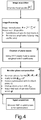
- Show a block diagram of the algorithm. Summarize the key steps for signal acquisition and processing and phase regeneration throughout optimization. Block diagram of the phase recovery algorithm. From top to bottom the focal image is captured and processed individualizing each main speckle maximum bl and position rl . There is a one to one correspondence between a DM tilt and rl . This tilt becomes the required plane wave phase Kl.For each speckle, 3 software-based variations of ϕ̂={ϕ̂ 1,ϕ̂ 2,ϕ̂ 3} are created with 3 piston phases θ={θ 1,θ 2,θ 3} applied to the current plane wave. Parabolic optimization is used to find the optimum phase for the best coupling. With each optimization ϕ̂ approaches to a fully optimized phase ϕ̂.
- Fig. 5
- Is an illustration of the single mode fiber coupling efficiency versus the number of corrected speckles for different turbulence conditions.
- The main idea is that the distorted phase front into the aperture can be restored as the sum of optimized plane waves. The number of plane waves is defined by the number M of main speckles in the focal plane. The optimization of each plane wave involves finding the relative phase shift between them, and this is done by using the coupled power as feedback. Since the optimization process is convex, only three measurements of the coupled power per plane wave variation are required. For this reason, all phase compensation requires only 3(M-1) iterations, making the method feasible in FSOC scenarios.
- A diagram of the turbulence compensation system is shown in
Fig. 3 where the laser beam passes through the turbulent atmosphere and reaches the optical receiver. At this point the wavefront P , which has experienced amplitude A and phase ϕ distortions, is captured by a single monolithic aperture and then guided and reflected in a deformable mirror. The DM introduces a phase-only compensation modifying its shape based on an estimated phase map ϕ̂. The reflected beam P c is now compensated in phase (ϕ-ϕ̂) maintaining the amplitude A unaltered. Here, ϕ̂ gradually changes as the resultant of an iterative sequential algorithm running in the computer. This algorithm requires two inputs hence the beam experiences a split in two arms. The first input is a single captured focal intensity image | F |2 (one image per field realization) that results of focusing the split beam into an infrared camera sensor. Here, F is the focal plane complex field of amplitude B and phase θ that results of the optical Fourier transform of P c. The second input is a real time acquisition of the power coupled in a single mode fiber (SMF). The coupled power is defined by the SMF coupling efficiency η which is calculated using the overlap integral of P c with the back propagated Gaussian fundamental mode of the fiber U 0 , with ∫| U 0|2=1, and* indicating complex conjugate, see Eq. (1).
- The working principle is based on the concept of angular wave spectrum "Angular Wave Spectrum Method", in which each field component in the focal plane results from the propagation of plane waves defined in the aperture. In this approach (
Fig. 4 ) we consider that the input field P = A exp(jϕ) in the aperture can be approximated as the sum of dominant plane waves exp(j K ), which define the large speckle characteristics in the focal plane. After an initial acquisition and processing of the focus intensity image | F |2 we classify the number of M main speckles based on their peak magnitude and spatial location. With this information, the Inverse Fourier Transform (IFT) can be used to obtain each plane wave.
- In Eq. (2), K l represents the tilt of each l plane wave. The scalars bl and θl are the peak amplitude and phase of the l speckle. Likewise the scalar θl is also the phase shift of the projected l pupil plane wave. Because the complex information in | F |2 is lost, the missing parameter for a full reconstruction of P is θl which cannot be directly measured but iteratively discovered. Hence, the phase compensation can be formulated as a multivariate optimization problem where the coefficients to be optimized are θl with l∈{1,2,...,M}.
- The reason of approximating the field P using only a discrete number of speckles, considering only the magnitude at the peaks as weighting factors of the plane waves, and their scalar phases as phase shifts of the plane waves, results of the analysis performed by [11]. This analysis show that even though intensity focal speckles are uncorrelated, every speckle shows local spatial correlation between its intensity distribution and phase gradients where minimum phase gradients are highly correlated with maximum slope of intensity. Consequently, it is sufficient to process only the M main speckles of higher intensity, considering solely their peak magnitude, local phase, and spatial coordinate of these peaks to define equal number of dominant plane waves.
- Because these M plane waves are uncorrelated, we can treat the multivariate optimization problem with the coordinate ascent algorithm. This method treats the multivariate problem as a set of simpler sub-problems of single dimension maximizing the objective function η by optimizing in sequence the scalar variables (coordinates) θl .

- The Eq. (3) represents the sequential optimization of each plane wave of Eq.(2). As previously mentioned, the weights bl and plane wave tilts K l are known, and the task involves finding the relative phase shift θl of each plane wave. During the optimization of one coordinate l, all others t≠l are kept fixed. Once finished, the recently adjusted θl becomes part of the set of t≠l fix coordinates and the next θ l+1 begin to be optimized. The process continues until the l=M variable is adjusted. The argument of the progressive sum of plane waves ϕ̂ (that is the result phase of the combined plane waves) reduces the relation ϕ-ϕ̂ for the compensated field P c in (
Fig. 3 ) and with each new optimization the objective η in Eq. (1) increases, as well as the number of focal speckles reduces due to the harmonic compensation in the pupil plane. The first plane wave in Eq. (3) does not need to be optimized since it represents the main focal speckle which requires only a general tilt correction providing the initial η improvement. Because the optimization problem is convex there is always a global maximum or minimum and it is required only three measurements of η in Eq. (1), after each variations of θl in Eq. (3), in order to find the optimum θl of each K l . This convexity property is a key factor to reduce the iteration number and fulfill FSOC time constraints. - Finally, the method is versatile and can also perform the correction directly in the focal plane of
Fig. 3 if the DM is located in such a position. For this, the incident field P could be split and focused in the camera, which would help to detect the speckles position and intensity distribution, and on the DM which should apply three piston phase variations, this time on the entire area of each speckle. The reflected beam is then collected by another lens located at equal focal distance and later focused into a SMF. This can be mathematically represented by Eq. (4) denote the 2D back Fourier transform which is performed optically. The resultant ϕ c represents the already compensated ϕ.
- This method is different from other iterative methods because:
- We know exactly which plane waves (pupil modes) needs to be optimized to correct the associated focal speckle. For this reason, it is not a blind optimization, but a well-defined systematic and controlled approach.
- We need only three power measurements to find the optimal phase shift of each plane wave. Since the plane wave phase shift in the aperture is 2n periodic, the coupled power also varies periodically. We only need 3 measurements to perform a parabolic approximation and find the optimum phase for a maximum.
- Since the average number of M main speckles to be processed is proportional to D/r 0, being D the telescope aperture diameter and r 0 the Fried parameter, the total number of iterations required for full field recovery 3(M-1) is also proportional to the D/r 0 of the turbulent scenario. This makes the approach feasible in FSOC.
- For a better understanding of the method and the required steps, a block diagram and graphical representation of the process involved is depicted in (
Fig. 5 ) and detailed as follows: - 1. Image acquisition: the IR camera in (
Fig. 3 ) captures a single realization of the focal intensity image | F |2. This image represents the first input of the "computer" block. - 2. Image processing: The required information for the creation of the plane waves is gathered. The image is normalized to the cumulative sum of all image components. Then, the M main intensity speckles are individualized and classified in descending order based on their maximums bl and spatial coordinates rl . Here, bl is the weighting factor of the plane wave in Eq. (2).
- 3. Creation of plane waves: The set of software-based plane waves are created. The rl and the IFFT are used to discover the associated plane wave phase tilts K l (DM shape). In practice a lookup table is created during the calibration process of the system, where each coordinate r in the focal plane is associated to the proper DM tilt. This tilt represents the required plane wave phase. In this fashion, each main speckle can have an associated software-based weighted plane wave. Up to now, the only missing term in Eq. (2) is the optimum estimated phase shift θ̂opt for each plane wave.
- 4. Iterative phase compensation: the estimated phase ϕ̂ for the field compensation is sequentially created. This implies a sequential discovery of θ̂opt for each plane wave, as shown in Eq. (3). Here, three software-based variations of the estimated pupil phase (DM shape) ϕ̂= {ϕ̂ 1,ϕ̂ 2,ϕ̂ 3} are created with 3 piston phases {θ 1 ,θ 2 ,θ 3} applied to the current plane wave. Each ϕ̂ is the argument of the sum of the current plane wave and the ones previously optimized. With each applied DM shape the coupled power η Eq. (1) is recorded. A parabolic fitting of η is used to discover the θ̂pt of the current plane wave. The estimated ϕ̂ represents the output of the 'computer' block in (
Fig. 3 ). - 5. Signal acquisition: The coupled power is measured and used as real time feedback for the optimization process. This signal represents the second input of the computer block in
Fig. 4 . - Finally, all M software-based plane waves have been summed up with the proper optimized phase shift θ̂opt . The resultant argument ϕ̂ defines the final shape of the DM that compensates the incident field (see
Fig. 3 ) and improves the overall coupled power Eq. (1). - Once a field realization has been corrected, a new focal image is captured. Within the coherence time of the field (around 1 millisecond in FSOC scenarios) the new phase realization does not evolve abruptly. The algorithm should actively decide the new M for the optimization and maintain the performance of the system at the presence of low phase distortion or even single speckle pattern. For this, it is necessary to keep track and use the previous θ̂opt as start value for the new estimates performing smaller variation to follow dynamically the phase evolution.
- The performance of the approach is shown in
Fig. 5 which shows how the coupling efficiency improves with the number of corrected speckles for different turbulent conditions. Assuming a telescope aperture of D=40cm (typical for FSOC), the range of turbulence conditions goes from low D/r 0=1.5 to very strong D/r 0=20.5. Although an expected D/r 0 for "LEO-to-Ground" scenarios should not exceed 11 and is likely to be around 5 for the above mentioned D, it is clear that the algorithm is perfectly capable of dealing with strong turbulence conditions. - If we consider an expected D/r 0 = 5.5, which is possible for elevations of 10° and telescope apertures of 40cm, the required number of corrected speckles for a coupling efficiency better than -3dB is M=8. This implies a number of iterations approximately equal to 3(8-1)=21, which would imply a control bandwidth of around 21kHz to deal with coherent times of 1 milliseconds. This control loop bandwidth, even though difficult, is not impossible and represents a
factor 5 reduction from the 100kHz required by other iterative methods. - The present invention can be used specifically in the following technical fields:
- Optical downlinks of satellites, airplanes or HAPS for high-level free-space optical communication systems
- Optical uplinks to satellite aircraft or HAPS can provide the downlink information of the downlink phase noise as pre-distortion of the signal.
- Optical transmission of frequency standards ("synchronization of optical clocks")
- Focusing the laser for high performance applications
- The present invention is described herein in detail as mentioned above. The disclosure of the invention also comprises the explanations of the invention as mentioned in the following paper of the inventors intended to be still published in Optical Society of America:
- "Sequential convex optimization technique for adaptive optics compensation in free-space laser communications"; Carlos E. Carrizo, Ramon Mata Calvo, and Aniceto Belmonte.
-
- AO
- adaptive optics
- DM
- deformable mirror
- OGS
- optical ground station
- SH
- Shack-Hartmann
- SMF
- single mode fiber
- WFS
- wavefront sensor
-
- [1] P-Y Madec, "Overview of Deformable Mirror Technologies for Adaptive Optics and Astronomy", European Southern Observatory
- [2] Hardy, "Adaptive Optics for Astronomical Telescopes", Oxford University Press, 1998
- [3] Barchers, J. D.; Fried, D. L. & Link, D. J., "Evaluation of the Performance of Hartmann Sensors in Strong Scintillation", Appl. Opt., OSA, 2002, 41, 1012-1021
- [4] Roddier, François, "Curvature sensing and compensation - a new concept in adaptive optics", Appl. Opt., OSA, 1988, 27, 1223-1225
- [5] Chew, T. Y.; Clare, R. M. & Lane, R. G., "A comparison of the Shack-Hartmann and pyramid wavefront sensors Optics Communications", 2006, 268, 189 - 195
- [6] Takeda,M., et.alt., "Fourier-transform method of fringe-pattern analysis for computer-based topography and interferometry", J. Opt. Soc. Am., OSA, 1982, 72, 156-160
- [7] Fienup, J.R., et.alt., "Comparison of Phase Diversity and Curvature Wavefront Sensing", Proc. of conference on Adaptive Optical System Technologies, SPIE, 1998, 3353
- [8] Murphy, K., et.alt., "Branch point detection and correction using the branch point potential method", Proc. SPIE,2008, 6951, 695105
- [9] Fienup, J. R., "Phase retrieval algorithms - a comparison", Appl. Opt., OSA, 1982, 21, 2758-2769
- [10] Anzuola, E. et.alt., "Performance of wavefront-sensorless adaptive optics using modal and zonal correction", Proc. Optics in Atmospheric Propagation and Adaptive Systems XIX ,SPIE, 2016, 10002, 100020J
- [11] Freund, I.,"Structural correlation in Gaussian random wave fields", Phys. Rev. E 51, 3770 (1995).
Claims (13)
- A method for detection of the modification parameters for modification of the optical characteristics of an optical element arranged in the optical path for modulated radiation of a receiver for optical free-space communication, for compensation of phase disturbances caused as a consequence of atmospheric turbulences, wherein, in said method- the radiation is focused, by means of a lens or other optical system, onto the center of a focal surface arranged in the focal plane,- the focal surface radiation pattern is captured by a camera,- individual radiation intensity speckles are identified within the focal surface by means of image processing software,- for each radiation intensity speckle, the position of the point of maximum radiation intensity is obtained,- to the point of maximum intensity of each radiation intensity speckle, a software-based plane wavefront is assigned, namely a tilting angle and a radiation energy are assigned to each plane wavefront on the basis of the position of the point of maximum intensity and of the radiation intensity of the associated speckle maximum thereof,- the plane wavefronts are sorted in accordance to the amount of the maximal intensities of the radiation intensity speckles, starting with the highest maximum intensity,- one of the wavefronts is selected as a reference wavefront,- on the basis of the reference wavefront, phase shifts of the wavefronts relative to each other are obtained,- the optical element is modified in correspondence to different phase shifts assumed per wavefront, wherein, for each plane wavefront, that assumed phase shift at which the energy of the radiation of the respective wavefront is maximal, is selected as the obtained phase shift assigned to this plane wavefront,- from the wavefronts, the energies of the radiation of the these wavefronts, the tilting angles and the detected phase shifts, there is obtained a set of modification parameters for the modification of the optical characteristics of the optical element required for compensation of the phase disturbances.
- The method according to claim 1, characterized in that the obtained phase shift of a wavefront is determined as that phase shift at which, with different modifications of the optical element, the energy of the radiation is maximal, wherein the optical element is modified by means of different sets of presettable parameters, each set among them corresponding to a different phase shift, and, each time, the energy of the radiation is metrologically obtained, wherein the obtained phase shift is that phase shift which results from the set of modification parameters at which the energy of the radiation of the respective plane wavefront is maximal.
- The method according to claim 1 or 2, characterized in that the maximum of the energy of the radiation is obtained on the basis of a curve passing through at least two and preferably three points which indicate the respective energy of the radiation at least two and preferably three assumed phase shifts in correspondence to which the optical element is deformed, wherein this curve is obtained by a fitting algorithm, particularly by convex optimization and preferably by hyperbolic fitting, and wherein the obtained phase shift is that phase shift at which the curve comprises its absolute maximum.
- The method according to any one of claims 1 to 3, characterized in that, as a reference wavefront, that plane wavefront is selected which is assigned to the radiation intensity speckle whose point of maximum intensity comprises the highest intensity of the points of maximum intensity of all radiation intensity speckles.
- The method according to claim 4, characterized in that, in case that a plurality of radiation intensity speckles exist that have points of maximum intensity with identical intensities, one radiation intensity speckle is selected among these radiation intensity speckles and that its assigned plane wavefront is used as a reference wavefront.
- The method according to any one of claims 1 to 5, characterized in- that the phase shift of a first wavefront relative to the reference wavefront is obtained and, on the basis of this phase shift and of the energy of the radiation of the wavefront and on the basis of the energy of the radiation and the tilting angle of the reference wavefront, a new reference wavefront is computed which is now defined inter alia by the energy of its radiation and by the resultant phase,- that the phase shift of a second wavefront relative to the new reference wavefront is obtained and, on the basis of this phase shift, the energy of the radiation of this wavefront and on the basis of the energy of the radiation and the phase of the reference wavefront, there is in turn computed a new reference wavefront,- that this procedure is performed for each wavefront for which no phase shift has yet been obtained,- that the set of modification parameters for the optical element is obtained on the basis of the energy of the radiation and the resultant phase of the last computed reference wavefront, wherein the resultant phase is an approximation of the desired phase and/or the best solution therefor for compensation of the phase disturbance, and- that the optical element is modified with respect to its optical characteristics in correspondence to the obtained modification parameters.
- The method according to any one of claims 1 to 6, characterized in that the modification parameters are used for modification of the shape of the optical element or for modification of the shape of an optical surface of the optical element that has a transmissive and/or reflective effect, and/or for modification of the optical characteristics of the optical element without deformation of the optical element.
- The method according to any one of claims 1 to 7, characterized in that the optical element is an optical transmission and/or reflection element.
- The method according to any one of claims 1 to 8, characterized in that the optical element is a mirror.
- The method according to any one of claims 1 to 9, characterized in that the optical element comprises an optical surface from which the radiation is conveyed onward toward the camera by transmission and/or reflection.
- The method according to any one of claims 1 to 10, characterized in that, for detection of the energy of the radiation and/or detection of the information of the radiation that is defined by the modulation, a part of the radiation is coupled into a single optical fiber.
- A device for reception of modulated radiation in optical free-space communication, comprising- a camera for capturing the intensity distribution of the received radiation focused on a focal plane,- an optical element variable in its optical characteristics and operative to convey received radiation onward toward the camera, and- an evaluation and control unit for evaluation of the camera image performed according to the method according to any one of preceding claims and for controlling the optical element so as to modify its optical characteristics.
- The device according to claim 12, characterized by an optical outcoupling unit arranged between the optical element and the camera for outcoupling a part of the modulated radiation and for incoupling into an optical single fiber so as to obtain the information determined by the modulation and, if required, for obtaining the energy of the radiation.
Priority Applications (1)
| Application Number | Priority Date | Filing Date | Title |
|---|---|---|---|
| EP17204456.2A EP3493430B1 (en) | 2017-11-29 | 2017-11-29 | Method for determining altering parameters for altering the optical features of an optical element for compensation of distortions in a beam for optical free-space communication |
Applications Claiming Priority (1)
| Application Number | Priority Date | Filing Date | Title |
|---|---|---|---|
| EP17204456.2A EP3493430B1 (en) | 2017-11-29 | 2017-11-29 | Method for determining altering parameters for altering the optical features of an optical element for compensation of distortions in a beam for optical free-space communication |
Publications (2)
| Publication Number | Publication Date |
|---|---|
| EP3493430A1 true EP3493430A1 (en) | 2019-06-05 |
| EP3493430B1 EP3493430B1 (en) | 2020-05-27 |
Family
ID=60673097
Family Applications (1)
| Application Number | Title | Priority Date | Filing Date |
|---|---|---|---|
| EP17204456.2A Active EP3493430B1 (en) | 2017-11-29 | 2017-11-29 | Method for determining altering parameters for altering the optical features of an optical element for compensation of distortions in a beam for optical free-space communication |
Country Status (1)
| Country | Link |
|---|---|
| EP (1) | EP3493430B1 (en) |
Cited By (6)
| Publication number | Priority date | Publication date | Assignee | Title |
|---|---|---|---|---|
| CN111510222A (en) * | 2020-03-25 | 2020-08-07 | 哈尔滨工业大学 | Atmospheric turbulence pre-compensation device for unmanned aerial vehicle and ground laser communication |
| WO2021260784A1 (en) * | 2020-06-23 | 2021-12-30 | 日本電信電話株式会社 | Phase difference distribution estimating method and phase difference distribution estimating device |
| CN116781174A (en) * | 2023-07-21 | 2023-09-19 | 北京理工大学 | FSO transmit power adaptive system based on atmospheric turbulence channel reciprocity |
| US20240372620A1 (en) * | 2023-05-03 | 2024-11-07 | Aalyria Technologies, Inc. | Optical wavelength diversity techniques for free-space optical communication |
| CN120802442A (en) * | 2025-09-16 | 2025-10-17 | 中国科学院光电技术研究所 | Single-mode fiber self-adaptive coupling method in turbulent environment |
| US12634009B2 (en) | 2024-04-30 | 2026-05-19 | Aalyria Technologies, Inc. | Gimbaled deformable mirror-based optical head for free-space optical communication |
Citations (2)
| Publication number | Priority date | Publication date | Assignee | Title |
|---|---|---|---|---|
| US20070278386A1 (en) * | 2006-06-05 | 2007-12-06 | General Dynamics Advanced Information Systems, Inc. | Measurement-diverse imaging and wavefront sensing with amplitude and phase estimation |
| EP2388934B1 (en) | 2010-05-22 | 2012-12-19 | Deutsches Zentrum für Luft- und Raumfahrt e.V. | Method for adjusting atmospherically distorted optical wave fronts |
-
2017
- 2017-11-29 EP EP17204456.2A patent/EP3493430B1/en active Active
Patent Citations (2)
| Publication number | Priority date | Publication date | Assignee | Title |
|---|---|---|---|---|
| US20070278386A1 (en) * | 2006-06-05 | 2007-12-06 | General Dynamics Advanced Information Systems, Inc. | Measurement-diverse imaging and wavefront sensing with amplitude and phase estimation |
| EP2388934B1 (en) | 2010-05-22 | 2012-12-19 | Deutsches Zentrum für Luft- und Raumfahrt e.V. | Method for adjusting atmospherically distorted optical wave fronts |
Non-Patent Citations (19)
| Title |
|---|
| ANZUOLA, E.: "Proc. Optics in Atmospheric Propagation and Adaptive Systems XIX", vol. 10002, 2016, SPIE, article "Performance of wavefront-sensorless adaptive optics using modal and zonal correction", pages: 100020J |
| BARCHERS, J. D.; FRIED, D. L.; LINK, D. J.: "Appl. Opt.", vol. 41, 2002, OSA, article "Evaluation of the Performance of Hartmann Sensors in Strong Scintillation", pages: 1012 - 1021 |
| CARLOS E. CARRIZO; RAMON MATA CALVO; ANICETO BELMONTE: "Sequential convex optimization technique for adaptive optics compensation in free-space laser communications", OPTICAL SOCIETY OF AMERICA |
| CHEW, T. Y.; CLARE, R. M.; LANE, R. G., A COMPARISON OF THE SHACK-HARTMANN AND PYRAMID WAVEFRONT SENSORS OPTICS COMMUNICATIONS, vol. 268, 2006, pages 189 - 195 |
| CHRISTINA MORFOPOULOU: "Wavefront sensorless Adaptive Optics System for Satellite-to-Ground Links", 21 July 2008 (2008-07-21), Oberpfaffenhofen, XP055472114, Retrieved from the Internet <URL:http://artemis.cslab.ntua.gr/el_thesis/artemis.ntua.ece/DT2008-0164/DT2008-0164.doc> [retrieved on 20180503] * |
| FIENUP, J. R.: "Appl. Opt.", vol. 21, 1982, OSA, article "Phase retrieval algorithms - a comparison", pages: 2758 - 2769 |
| FIENUP, J.R.: "Proc. of conference on Adaptive Optical System Technologies", 1998, SPIE, article "Comparison of Phase Diversity and Curvature Wavefront Sensing", pages: 3353 |
| FREUND, I.: "Structural correlation in Gaussian random wave fields", PHYS. REV., vol. E 51, 1995, pages 3770 |
| HARDY: "Adaptive Optics for Astronomical Telescopes", 1998, OXFORD UNIVERSITY PRESS |
| HUANG LINHAI ET AL: "Wavefront sensorless adaptive optics: a general model-based approach", OPTICS EXPRESS, 3 January 2011 (2011-01-03), United States, pages 371 - 4474, XP055472146, Retrieved from the Internet <URL:https://www.osapublishing.org/DirectPDFAccess/71F770B3-9D31-DAA7-8913ED81A9E54FEE_209129/oe-19-1-371.pdf?da=1&id=209129&seq=0&mobile=no> [retrieved on 20180503], DOI: 10.1364/OE.19.000371 * |
| HUIZHEN YANG ET AL: "Model-based wavefront sensorless adaptive optics system for large aberrations and extended objects", OPTICS EXPRESS, vol. 23, no. 19, 10 September 2015 (2015-09-10), pages 24587, XP055472143, DOI: 10.1364/OE.23.024587 * |
| HUIZHEN YANG ET AL: "Performance Comparison of Wavefront-Sensorless Adaptive Optics Systems by Using of the Focal Plane", INTERNATIONAL JOURNAL OF OPTICS, vol. 2015, 1 January 2015 (2015-01-01), pages 1 - 8, XP055472138, ISSN: 1687-9384, DOI: 10.1155/2015/985351 * |
| ISAAC FREUND ET AL: "Structural correlations in Gaussian random wave fields", PHYSICAL REVIEW E. STATISTICAL PHYSICS, PLASMAS, FLUIDS, AND RELATED INTERDISCIPLINARY TOPICS., vol. 51, no. 4, 1 April 1995 (1995-04-01), US, pages 3770 - 3773, XP055471856, ISSN: 1063-651X, DOI: 10.1103/PhysRevE.51.3770 * |
| MURPHY, K.: "Branch point detection and correction using the branch point potential method", PROC. SPIE, vol. 6951, 2008, pages 695105 |
| PENGZHI JIANG ET AL: "A new performance metric on sensorless adaptive optics imaging system", OPTIK., vol. 127, no. 1, 1 January 2016 (2016-01-01), DE, pages 222 - 226, XP055472134, ISSN: 0030-4026, DOI: 10.1016/j.ijleo.2015.10.051 * |
| P-Y MADEC: "Overview of Deformable Mirror Technologies for Adaptive Optics and Astronomy", EUROPEAN SOUTHERN OBSERVATORY |
| RODDIER; FRANGOIS: "Appl. Opt.", vol. 27, 1988, OSA, article "Curvature sensing and compensation - a new concept in adaptive optics", pages: 1223 - 1225 |
| TAKEDA,M.: "J. Opt. Soc. Am.", vol. 72, 1982, OSA, article "Fourier-transform method of fringe-pattern analysis for computer-based topography and interferometry", pages: 156 - 160 |
| V. A. BOGACHEV ET AL: "Numerical simulation of sensorless adaptive phase correction of regular, vortical, and incoherent multimode laser beams", ATMOSPHERIC AND OCEANIC OPTICS, vol. 30, no. 2, 1 March 2017 (2017-03-01), RU, pages 191 - 197, XP055472086, ISSN: 1024-8560, DOI: 10.1134/S1024856017020051 * |
Cited By (8)
| Publication number | Priority date | Publication date | Assignee | Title |
|---|---|---|---|---|
| CN111510222A (en) * | 2020-03-25 | 2020-08-07 | 哈尔滨工业大学 | Atmospheric turbulence pre-compensation device for unmanned aerial vehicle and ground laser communication |
| WO2021260784A1 (en) * | 2020-06-23 | 2021-12-30 | 日本電信電話株式会社 | Phase difference distribution estimating method and phase difference distribution estimating device |
| JPWO2021260784A1 (en) * | 2020-06-23 | 2021-12-30 | ||
| US20240372620A1 (en) * | 2023-05-03 | 2024-11-07 | Aalyria Technologies, Inc. | Optical wavelength diversity techniques for free-space optical communication |
| CN116781174A (en) * | 2023-07-21 | 2023-09-19 | 北京理工大学 | FSO transmit power adaptive system based on atmospheric turbulence channel reciprocity |
| US12634009B2 (en) | 2024-04-30 | 2026-05-19 | Aalyria Technologies, Inc. | Gimbaled deformable mirror-based optical head for free-space optical communication |
| CN120802442A (en) * | 2025-09-16 | 2025-10-17 | 中国科学院光电技术研究所 | Single-mode fiber self-adaptive coupling method in turbulent environment |
| CN120802442B (en) * | 2025-09-16 | 2025-12-12 | 中国科学院光电技术研究所 | Single-mode fiber self-adaptive coupling method in turbulent environment |
Also Published As
| Publication number | Publication date |
|---|---|
| EP3493430B1 (en) | 2020-05-27 |
Similar Documents
| Publication | Publication Date | Title |
|---|---|---|
| EP3493430B1 (en) | Method for determining altering parameters for altering the optical features of an optical element for compensation of distortions in a beam for optical free-space communication | |
| US7437077B2 (en) | Wavefront sensing system employing active updating of reference positions and subaperture locations on wavefront sensor | |
| Weyrauch et al. | Free-space laser communications with adaptive optics: Atmospheric compensation experiments | |
| Weyrauch et al. | Atmospheric compensation with a speckle beacon in strong scintillation conditions: directed energy and laser communication applications | |
| US20060024061A1 (en) | Wavefront sensing system employing active updating of reference positions and subaperture locations on wavefront sensor | |
| Minowa et al. | Performance of Subaru adaptive optics system AO188 | |
| Vorontsov et al. | Comparative efficiency analysis of fiber-array and conventional beam director systems in volume turbulence | |
| CA2957523C (en) | Apparatus and method for reducing signal fading due to atmospheric turbulence | |
| JP6920710B2 (en) | Spatial optical communication device and method | |
| Petit et al. | Investigation on adaptive optics performance from propagation channel characterization with the small optical transponder | |
| US6452146B1 (en) | Electro-optical field conjugation system | |
| Tyler | Adaptive optics compensation for propagation through deep turbulence: a study of some interesting approaches | |
| Petit et al. | Adaptive optics results with SOTA | |
| Carrizo et al. | Proof of concept for adaptive sequential optimization of free-space communication receivers | |
| Vasylyev et al. | Characterization of free-space quantum channels | |
| Zhao et al. | Adaptive optical communication through turbulent atmospheric channels | |
| Stewart et al. | Comparing adaptive optics approaches for NASA LCRD Ground Station# 2 | |
| US6818876B1 (en) | Scintillation-immune adaptive optics reconstructor | |
| CN117666157A (en) | Complex amplitude SLM adaptive optical path alignment system and method under disturbed channel environment | |
| Aldecocea et al. | Impact of transmitter wavefront errors and pointing jitter on intersatellite free space optical communications | |
| CN106788716A (en) | Micro reflector array wavefront sensing apparatus and method | |
| Wang et al. | Denoising and predictive tracking method for the beacon in intersatellite laser communications | |
| Camboulives et al. | Optical ground station optimization for future optical geostationary satellite feeder uplinks | |
| Barrios et al. | Adaptive optics for free space optical communications | |
| TWI912527B (en) | Method of improving information transmission rate in optical communication and information transmission system |
Legal Events
| Date | Code | Title | Description |
|---|---|---|---|
| PUAI | Public reference made under article 153(3) epc to a published international application that has entered the european phase |
Free format text: ORIGINAL CODE: 0009012 |
|
| STAA | Information on the status of an ep patent application or granted ep patent |
Free format text: STATUS: THE APPLICATION HAS BEEN PUBLISHED |
|
| AK | Designated contracting states |
Kind code of ref document: A1 Designated state(s): AL AT BE BG CH CY CZ DE DK EE ES FI FR GB GR HR HU IE IS IT LI LT LU LV MC MK MT NL NO PL PT RO RS SE SI SK SM TR |
|
| AX | Request for extension of the european patent |
Extension state: BA ME |
|
| RAP1 | Party data changed (applicant data changed or rights of an application transferred) |
Owner name: UNIVERSITAT POLITECNICA DE CATALUNYA |
|
| RAP1 | Party data changed (applicant data changed or rights of an application transferred) |
Owner name: DEUTSCHES ZENTRUM FUER LUFT- UND RAUMFAHRT E.V. Owner name: UNIVERSITAT POLITECNICA DE CATALUNYA |
|
| STAA | Information on the status of an ep patent application or granted ep patent |
Free format text: STATUS: REQUEST FOR EXAMINATION WAS MADE |
|
| 17P | Request for examination filed |
Effective date: 20190927 |
|
| RBV | Designated contracting states (corrected) |
Designated state(s): AL AT BE BG CH CY CZ DE DK EE ES FI FR GB GR HR HU IE IS IT LI LT LU LV MC MK MT NL NO PL PT RO RS SE SI SK SM TR |
|
| GRAP | Despatch of communication of intention to grant a patent |
Free format text: ORIGINAL CODE: EPIDOSNIGR1 |
|
| STAA | Information on the status of an ep patent application or granted ep patent |
Free format text: STATUS: GRANT OF PATENT IS INTENDED |
|
| INTG | Intention to grant announced |
Effective date: 20191210 |
|
| GRAS | Grant fee paid |
Free format text: ORIGINAL CODE: EPIDOSNIGR3 |
|
| GRAA | (expected) grant |
Free format text: ORIGINAL CODE: 0009210 |
|
| STAA | Information on the status of an ep patent application or granted ep patent |
Free format text: STATUS: THE PATENT HAS BEEN GRANTED |
|
| AK | Designated contracting states |
Kind code of ref document: B1 Designated state(s): AL AT BE BG CH CY CZ DE DK EE ES FI FR GB GR HR HU IE IS IT LI LT LU LV MC MK MT NL NO PL PT RO RS SE SI SK SM TR |
|
| REG | Reference to a national code |
Ref country code: GB Ref legal event code: FG4D |
|
| REG | Reference to a national code |
Ref country code: CH Ref legal event code: EP |
|
| REG | Reference to a national code |
Ref country code: AT Ref legal event code: REF Ref document number: 1275651 Country of ref document: AT Kind code of ref document: T Effective date: 20200615 |
|
| REG | Reference to a national code |
Ref country code: DE Ref legal event code: R096 Ref document number: 602017017236 Country of ref document: DE |
|
| REG | Reference to a national code |
Ref country code: NL Ref legal event code: FP |
|
| REG | Reference to a national code |
Ref country code: LT Ref legal event code: MG4D |
|
| PG25 | Lapsed in a contracting state [announced via postgrant information from national office to epo] |
Ref country code: GR Free format text: LAPSE BECAUSE OF FAILURE TO SUBMIT A TRANSLATION OF THE DESCRIPTION OR TO PAY THE FEE WITHIN THE PRESCRIBED TIME-LIMIT Effective date: 20200828 Ref country code: NO Free format text: LAPSE BECAUSE OF FAILURE TO SUBMIT A TRANSLATION OF THE DESCRIPTION OR TO PAY THE FEE WITHIN THE PRESCRIBED TIME-LIMIT Effective date: 20200827 Ref country code: FI Free format text: LAPSE BECAUSE OF FAILURE TO SUBMIT A TRANSLATION OF THE DESCRIPTION OR TO PAY THE FEE WITHIN THE PRESCRIBED TIME-LIMIT Effective date: 20200527 Ref country code: LT Free format text: LAPSE BECAUSE OF FAILURE TO SUBMIT A TRANSLATION OF THE DESCRIPTION OR TO PAY THE FEE WITHIN THE PRESCRIBED TIME-LIMIT Effective date: 20200527 Ref country code: IS Free format text: LAPSE BECAUSE OF FAILURE TO SUBMIT A TRANSLATION OF THE DESCRIPTION OR TO PAY THE FEE WITHIN THE PRESCRIBED TIME-LIMIT Effective date: 20200927 Ref country code: SE Free format text: LAPSE BECAUSE OF FAILURE TO SUBMIT A TRANSLATION OF THE DESCRIPTION OR TO PAY THE FEE WITHIN THE PRESCRIBED TIME-LIMIT Effective date: 20200527 Ref country code: PT Free format text: LAPSE BECAUSE OF FAILURE TO SUBMIT A TRANSLATION OF THE DESCRIPTION OR TO PAY THE FEE WITHIN THE PRESCRIBED TIME-LIMIT Effective date: 20200928 |
|
| PG25 | Lapsed in a contracting state [announced via postgrant information from national office to epo] |
Ref country code: BG Free format text: LAPSE BECAUSE OF FAILURE TO SUBMIT A TRANSLATION OF THE DESCRIPTION OR TO PAY THE FEE WITHIN THE PRESCRIBED TIME-LIMIT Effective date: 20200827 Ref country code: RS Free format text: LAPSE BECAUSE OF FAILURE TO SUBMIT A TRANSLATION OF THE DESCRIPTION OR TO PAY THE FEE WITHIN THE PRESCRIBED TIME-LIMIT Effective date: 20200527 Ref country code: LV Free format text: LAPSE BECAUSE OF FAILURE TO SUBMIT A TRANSLATION OF THE DESCRIPTION OR TO PAY THE FEE WITHIN THE PRESCRIBED TIME-LIMIT Effective date: 20200527 Ref country code: HR Free format text: LAPSE BECAUSE OF FAILURE TO SUBMIT A TRANSLATION OF THE DESCRIPTION OR TO PAY THE FEE WITHIN THE PRESCRIBED TIME-LIMIT Effective date: 20200527 |
|
| REG | Reference to a national code |
Ref country code: AT Ref legal event code: MK05 Ref document number: 1275651 Country of ref document: AT Kind code of ref document: T Effective date: 20200527 |
|
| PG25 | Lapsed in a contracting state [announced via postgrant information from national office to epo] |
Ref country code: AL Free format text: LAPSE BECAUSE OF FAILURE TO SUBMIT A TRANSLATION OF THE DESCRIPTION OR TO PAY THE FEE WITHIN THE PRESCRIBED TIME-LIMIT Effective date: 20200527 |
|
| PG25 | Lapsed in a contracting state [announced via postgrant information from national office to epo] |
Ref country code: ES Free format text: LAPSE BECAUSE OF FAILURE TO SUBMIT A TRANSLATION OF THE DESCRIPTION OR TO PAY THE FEE WITHIN THE PRESCRIBED TIME-LIMIT Effective date: 20200527 Ref country code: DK Free format text: LAPSE BECAUSE OF FAILURE TO SUBMIT A TRANSLATION OF THE DESCRIPTION OR TO PAY THE FEE WITHIN THE PRESCRIBED TIME-LIMIT Effective date: 20200527 Ref country code: EE Free format text: LAPSE BECAUSE OF FAILURE TO SUBMIT A TRANSLATION OF THE DESCRIPTION OR TO PAY THE FEE WITHIN THE PRESCRIBED TIME-LIMIT Effective date: 20200527 Ref country code: SM Free format text: LAPSE BECAUSE OF FAILURE TO SUBMIT A TRANSLATION OF THE DESCRIPTION OR TO PAY THE FEE WITHIN THE PRESCRIBED TIME-LIMIT Effective date: 20200527 Ref country code: CZ Free format text: LAPSE BECAUSE OF FAILURE TO SUBMIT A TRANSLATION OF THE DESCRIPTION OR TO PAY THE FEE WITHIN THE PRESCRIBED TIME-LIMIT Effective date: 20200527 Ref country code: AT Free format text: LAPSE BECAUSE OF FAILURE TO SUBMIT A TRANSLATION OF THE DESCRIPTION OR TO PAY THE FEE WITHIN THE PRESCRIBED TIME-LIMIT Effective date: 20200527 Ref country code: RO Free format text: LAPSE BECAUSE OF FAILURE TO SUBMIT A TRANSLATION OF THE DESCRIPTION OR TO PAY THE FEE WITHIN THE PRESCRIBED TIME-LIMIT Effective date: 20200527 |
|
| PG25 | Lapsed in a contracting state [announced via postgrant information from national office to epo] |
Ref country code: PL Free format text: LAPSE BECAUSE OF FAILURE TO SUBMIT A TRANSLATION OF THE DESCRIPTION OR TO PAY THE FEE WITHIN THE PRESCRIBED TIME-LIMIT Effective date: 20200527 Ref country code: SK Free format text: LAPSE BECAUSE OF FAILURE TO SUBMIT A TRANSLATION OF THE DESCRIPTION OR TO PAY THE FEE WITHIN THE PRESCRIBED TIME-LIMIT Effective date: 20200527 |
|
| REG | Reference to a national code |
Ref country code: DE Ref legal event code: R097 Ref document number: 602017017236 Country of ref document: DE |
|
| PLBE | No opposition filed within time limit |
Free format text: ORIGINAL CODE: 0009261 |
|
| STAA | Information on the status of an ep patent application or granted ep patent |
Free format text: STATUS: NO OPPOSITION FILED WITHIN TIME LIMIT |
|
| 26N | No opposition filed |
Effective date: 20210302 |
|
| PG25 | Lapsed in a contracting state [announced via postgrant information from national office to epo] |
Ref country code: SI Free format text: LAPSE BECAUSE OF FAILURE TO SUBMIT A TRANSLATION OF THE DESCRIPTION OR TO PAY THE FEE WITHIN THE PRESCRIBED TIME-LIMIT Effective date: 20200527 |
|
| PG25 | Lapsed in a contracting state [announced via postgrant information from national office to epo] |
Ref country code: MC Free format text: LAPSE BECAUSE OF FAILURE TO SUBMIT A TRANSLATION OF THE DESCRIPTION OR TO PAY THE FEE WITHIN THE PRESCRIBED TIME-LIMIT Effective date: 20200527 |
|
| REG | Reference to a national code |
Ref country code: CH Ref legal event code: PL |
|
| PG25 | Lapsed in a contracting state [announced via postgrant information from national office to epo] |
Ref country code: LU Free format text: LAPSE BECAUSE OF NON-PAYMENT OF DUE FEES Effective date: 20201129 |
|
| REG | Reference to a national code |
Ref country code: BE Ref legal event code: MM Effective date: 20201130 |
|
| PG25 | Lapsed in a contracting state [announced via postgrant information from national office to epo] |
Ref country code: CH Free format text: LAPSE BECAUSE OF NON-PAYMENT OF DUE FEES Effective date: 20201130 Ref country code: LI Free format text: LAPSE BECAUSE OF NON-PAYMENT OF DUE FEES Effective date: 20201130 |
|
| REG | Reference to a national code |
Ref country code: IE Ref legal event code: MM4A |
|
| PG25 | Lapsed in a contracting state [announced via postgrant information from national office to epo] |
Ref country code: IE Free format text: LAPSE BECAUSE OF NON-PAYMENT OF DUE FEES Effective date: 20201129 |
|
| PG25 | Lapsed in a contracting state [announced via postgrant information from national office to epo] |
Ref country code: TR Free format text: LAPSE BECAUSE OF FAILURE TO SUBMIT A TRANSLATION OF THE DESCRIPTION OR TO PAY THE FEE WITHIN THE PRESCRIBED TIME-LIMIT Effective date: 20200527 Ref country code: MT Free format text: LAPSE BECAUSE OF FAILURE TO SUBMIT A TRANSLATION OF THE DESCRIPTION OR TO PAY THE FEE WITHIN THE PRESCRIBED TIME-LIMIT Effective date: 20200527 Ref country code: CY Free format text: LAPSE BECAUSE OF FAILURE TO SUBMIT A TRANSLATION OF THE DESCRIPTION OR TO PAY THE FEE WITHIN THE PRESCRIBED TIME-LIMIT Effective date: 20200527 |
|
| PG25 | Lapsed in a contracting state [announced via postgrant information from national office to epo] |
Ref country code: MK Free format text: LAPSE BECAUSE OF FAILURE TO SUBMIT A TRANSLATION OF THE DESCRIPTION OR TO PAY THE FEE WITHIN THE PRESCRIBED TIME-LIMIT Effective date: 20200527 |
|
| GBPC | Gb: european patent ceased through non-payment of renewal fee |
Effective date: 20211129 |
|
| PG25 | Lapsed in a contracting state [announced via postgrant information from national office to epo] |
Ref country code: BE Free format text: LAPSE BECAUSE OF NON-PAYMENT OF DUE FEES Effective date: 20201130 |
|
| PG25 | Lapsed in a contracting state [announced via postgrant information from national office to epo] |
Ref country code: GB Free format text: LAPSE BECAUSE OF NON-PAYMENT OF DUE FEES Effective date: 20211129 |
|
| PGFP | Annual fee paid to national office [announced via postgrant information from national office to epo] |
Ref country code: NL Payment date: 20231012 Year of fee payment: 7 |
|
| PGFP | Annual fee paid to national office [announced via postgrant information from national office to epo] |
Ref country code: IT Payment date: 20231114 Year of fee payment: 7 Ref country code: FR Payment date: 20231010 Year of fee payment: 7 |
|
| REG | Reference to a national code |
Ref country code: NL Ref legal event code: MM Effective date: 20241201 |
|
| PG25 | Lapsed in a contracting state [announced via postgrant information from national office to epo] |
Ref country code: NL Free format text: LAPSE BECAUSE OF NON-PAYMENT OF DUE FEES Effective date: 20241201 |
|
| PG25 | Lapsed in a contracting state [announced via postgrant information from national office to epo] |
Ref country code: IT Free format text: LAPSE BECAUSE OF NON-PAYMENT OF DUE FEES Effective date: 20241129 |
|
| PG25 | Lapsed in a contracting state [announced via postgrant information from national office to epo] |
Ref country code: FR Free format text: LAPSE BECAUSE OF NON-PAYMENT OF DUE FEES Effective date: 20241130 |
|
| PGFP | Annual fee paid to national office [announced via postgrant information from national office to epo] |
Ref country code: DE Payment date: 20251013 Year of fee payment: 9 |