EP3493427A1 - Providing space division multiple access in a wireless network - Google Patents
Providing space division multiple access in a wireless network Download PDFInfo
- Publication number
- EP3493427A1 EP3493427A1 EP19152460.2A EP19152460A EP3493427A1 EP 3493427 A1 EP3493427 A1 EP 3493427A1 EP 19152460 A EP19152460 A EP 19152460A EP 3493427 A1 EP3493427 A1 EP 3493427A1
- Authority
- EP
- European Patent Office
- Prior art keywords
- mobile station
- beams
- indication
- base station
- receiving
- Prior art date
- Legal status (The legal status is an assumption and is not a legal conclusion. Google has not performed a legal analysis and makes no representation as to the accuracy of the status listed.)
- Granted
Links
Images

Classifications
-
- H—ELECTRICITY
- H04—ELECTRIC COMMUNICATION TECHNIQUE
- H04B—TRANSMISSION
- H04B7/00—Radio transmission systems, i.e. using radiation field
- H04B7/02—Diversity systems; Multi-antenna system, i.e. transmission or reception using multiple antennas
- H04B7/04—Diversity systems; Multi-antenna system, i.e. transmission or reception using multiple antennas using two or more spaced independent antennas
- H04B7/06—Diversity systems; Multi-antenna system, i.e. transmission or reception using multiple antennas using two or more spaced independent antennas at the transmitting station
- H04B7/0686—Hybrid systems, i.e. switching and simultaneous transmission
- H04B7/0695—Hybrid systems, i.e. switching and simultaneous transmission using beam selection
- H04B7/06952—Selecting one or more beams from a plurality of beams, e.g. beam training, management or sweeping
-
- H—ELECTRICITY
- H04—ELECTRIC COMMUNICATION TECHNIQUE
- H04B—TRANSMISSION
- H04B7/00—Radio transmission systems, i.e. using radiation field
- H04B7/02—Diversity systems; Multi-antenna system, i.e. transmission or reception using multiple antennas
- H04B7/04—Diversity systems; Multi-antenna system, i.e. transmission or reception using multiple antennas using two or more spaced independent antennas
- H04B7/0408—Diversity systems; Multi-antenna system, i.e. transmission or reception using multiple antennas using two or more spaced independent antennas using two or more beams, i.e. beam diversity
-
- H—ELECTRICITY
- H04—ELECTRIC COMMUNICATION TECHNIQUE
- H04B—TRANSMISSION
- H04B7/00—Radio transmission systems, i.e. using radiation field
- H04B7/02—Diversity systems; Multi-antenna system, i.e. transmission or reception using multiple antennas
- H04B7/04—Diversity systems; Multi-antenna system, i.e. transmission or reception using multiple antennas using two or more spaced independent antennas
- H04B7/0413—MIMO systems
- H04B7/0456—Selection of precoding matrices or codebooks, e.g. using matrices antenna weighting
-
- H—ELECTRICITY
- H04—ELECTRIC COMMUNICATION TECHNIQUE
- H04B—TRANSMISSION
- H04B7/00—Radio transmission systems, i.e. using radiation field
- H04B7/02—Diversity systems; Multi-antenna system, i.e. transmission or reception using multiple antennas
- H04B7/04—Diversity systems; Multi-antenna system, i.e. transmission or reception using multiple antennas using two or more spaced independent antennas
- H04B7/06—Diversity systems; Multi-antenna system, i.e. transmission or reception using multiple antennas using two or more spaced independent antennas at the transmitting station
- H04B7/0613—Diversity systems; Multi-antenna system, i.e. transmission or reception using multiple antennas using two or more spaced independent antennas at the transmitting station using simultaneous transmission
- H04B7/0615—Diversity systems; Multi-antenna system, i.e. transmission or reception using multiple antennas using two or more spaced independent antennas at the transmitting station using simultaneous transmission of weighted versions of same signal
- H04B7/0619—Diversity systems; Multi-antenna system, i.e. transmission or reception using multiple antennas using two or more spaced independent antennas at the transmitting station using simultaneous transmission of weighted versions of same signal using feedback from receiving side
- H04B7/0621—Feedback content
- H04B7/063—Parameters other than those covered in groups H04B7/0623 - H04B7/0634, e.g. channel matrix rank or transmit mode selection
-
- H—ELECTRICITY
- H04—ELECTRIC COMMUNICATION TECHNIQUE
- H04B—TRANSMISSION
- H04B7/00—Radio transmission systems, i.e. using radiation field
- H04B7/02—Diversity systems; Multi-antenna system, i.e. transmission or reception using multiple antennas
- H04B7/04—Diversity systems; Multi-antenna system, i.e. transmission or reception using multiple antennas using two or more spaced independent antennas
- H04B7/06—Diversity systems; Multi-antenna system, i.e. transmission or reception using multiple antennas using two or more spaced independent antennas at the transmitting station
- H04B7/0613—Diversity systems; Multi-antenna system, i.e. transmission or reception using multiple antennas using two or more spaced independent antennas at the transmitting station using simultaneous transmission
- H04B7/0615—Diversity systems; Multi-antenna system, i.e. transmission or reception using multiple antennas using two or more spaced independent antennas at the transmitting station using simultaneous transmission of weighted versions of same signal
- H04B7/0619—Diversity systems; Multi-antenna system, i.e. transmission or reception using multiple antennas using two or more spaced independent antennas at the transmitting station using simultaneous transmission of weighted versions of same signal using feedback from receiving side
- H04B7/0621—Feedback content
- H04B7/0632—Channel quality parameters, e.g. channel quality indicator [CQI]
-
- H—ELECTRICITY
- H04—ELECTRIC COMMUNICATION TECHNIQUE
- H04B—TRANSMISSION
- H04B7/00—Radio transmission systems, i.e. using radiation field
- H04B7/02—Diversity systems; Multi-antenna system, i.e. transmission or reception using multiple antennas
- H04B7/04—Diversity systems; Multi-antenna system, i.e. transmission or reception using multiple antennas using two or more spaced independent antennas
- H04B7/06—Diversity systems; Multi-antenna system, i.e. transmission or reception using multiple antennas using two or more spaced independent antennas at the transmitting station
- H04B7/0613—Diversity systems; Multi-antenna system, i.e. transmission or reception using multiple antennas using two or more spaced independent antennas at the transmitting station using simultaneous transmission
- H04B7/0615—Diversity systems; Multi-antenna system, i.e. transmission or reception using multiple antennas using two or more spaced independent antennas at the transmitting station using simultaneous transmission of weighted versions of same signal
- H04B7/0619—Diversity systems; Multi-antenna system, i.e. transmission or reception using multiple antennas using two or more spaced independent antennas at the transmitting station using simultaneous transmission of weighted versions of same signal using feedback from receiving side
- H04B7/0636—Feedback format
- H04B7/0639—Using selective indices, e.g. of a codebook, e.g. pre-distortion matrix index [PMI] or for beam selection
-
- H—ELECTRICITY
- H04—ELECTRIC COMMUNICATION TECHNIQUE
- H04B—TRANSMISSION
- H04B7/00—Radio transmission systems, i.e. using radiation field
- H04B7/02—Diversity systems; Multi-antenna system, i.e. transmission or reception using multiple antennas
- H04B7/04—Diversity systems; Multi-antenna system, i.e. transmission or reception using multiple antennas using two or more spaced independent antennas
- H04B7/06—Diversity systems; Multi-antenna system, i.e. transmission or reception using multiple antennas using two or more spaced independent antennas at the transmitting station
- H04B7/0686—Hybrid systems, i.e. switching and simultaneous transmission
- H04B7/0695—Hybrid systems, i.e. switching and simultaneous transmission using beam selection
-
- H—ELECTRICITY
- H04—ELECTRIC COMMUNICATION TECHNIQUE
- H04B—TRANSMISSION
- H04B7/00—Radio transmission systems, i.e. using radiation field
- H04B7/02—Diversity systems; Multi-antenna system, i.e. transmission or reception using multiple antennas
- H04B7/04—Diversity systems; Multi-antenna system, i.e. transmission or reception using multiple antennas using two or more spaced independent antennas
- H04B7/06—Diversity systems; Multi-antenna system, i.e. transmission or reception using multiple antennas using two or more spaced independent antennas at the transmitting station
- H04B7/0697—Diversity systems; Multi-antenna system, i.e. transmission or reception using multiple antennas using two or more spaced independent antennas at the transmitting station using spatial multiplexing
-
- H—ELECTRICITY
- H04—ELECTRIC COMMUNICATION TECHNIQUE
- H04B—TRANSMISSION
- H04B7/00—Radio transmission systems, i.e. using radiation field
- H04B7/02—Diversity systems; Multi-antenna system, i.e. transmission or reception using multiple antennas
- H04B7/04—Diversity systems; Multi-antenna system, i.e. transmission or reception using multiple antennas using two or more spaced independent antennas
- H04B7/08—Diversity systems; Multi-antenna system, i.e. transmission or reception using multiple antennas using two or more spaced independent antennas at the receiving station
- H04B7/0868—Hybrid systems, i.e. switching and combining
- H04B7/088—Hybrid systems, i.e. switching and combining using beam selection
-
- H—ELECTRICITY
- H04—ELECTRIC COMMUNICATION TECHNIQUE
- H04B—TRANSMISSION
- H04B7/00—Radio transmission systems, i.e. using radiation field
- H04B7/02—Diversity systems; Multi-antenna system, i.e. transmission or reception using multiple antennas
- H04B7/04—Diversity systems; Multi-antenna system, i.e. transmission or reception using multiple antennas using two or more spaced independent antennas
- H04B7/06—Diversity systems; Multi-antenna system, i.e. transmission or reception using multiple antennas using two or more spaced independent antennas at the transmitting station
- H04B7/0602—Diversity systems; Multi-antenna system, i.e. transmission or reception using multiple antennas using two or more spaced independent antennas at the transmitting station using antenna switching
- H04B7/0608—Antenna selection according to transmission parameters
- H04B7/061—Antenna selection according to transmission parameters using feedback from receiving side
-
- H—ELECTRICITY
- H04—ELECTRIC COMMUNICATION TECHNIQUE
- H04W—WIRELESS COMMUNICATION NETWORKS
- H04W74/00—Wireless channel access
Definitions
- the invention relates generally to providing space division multiple access (SDMA) in a wireless network.
- SDMA space division multiple access
- wireless access technologies have been proposed or implemented to enable mobile stations to perform communications with other mobile stations or with wired terminals coupled to wired networks.
- wireless access technologies include GSM (Global System for Mobile communications) or UMTS (Universal Mobile Telecommunications System) technologies, defined by the Third Generation Partnership Project (3GPP); CDMA 2000 (Code Division Multiple Access 2000) technologies, defined by 3GPP2; or other wireless access technologies.
- GSM Global System for Mobile communications
- UMTS Universal Mobile Telecommunications System
- 3GPP Third Generation Partnership Project
- CDMA 2000 Code Division Multiple Access 2000
- LTE Long Term Evolution
- SDMA space division multiple access
- RF radio frequency
- a method of providing space division multiple access in a wireless network includes transmitting plural beams within a cell segment, and sending different information sets in the corresponding plural beams, where one or both of the information sets are detectable by a mobile station depending upon a location of the mobile station. Beam selection is performed from among the plural beams according to the received indication that is responsive to which of the plural information sets is detected by the mobile station.
- Fig. 1 shows an exemplary wireless network in which a spatial division multiple access (SDMA) mechanism according to preferred embodiments is provided.
- the wireless network includes a base station 100 that includes an antenna array or other assembly (multi-beam antenna) 102 for producing multiple beams (spatial beams) 104, 106 in a corresponding cell sector 108. Although just two beams 104 and 106 are depicted in Fig. 1 , it is noted that more than two beams can be provided in a cell sector in other embodiments.
- SDMA enables radio frequency (RF) resources (e.g., frequencies, time slots, etc.) to be reused in different geographic regions of a cell sector by transmitting different beams into the different geographic regions using multi-beam antennas.
- RF radio frequency
- a “beam” (or “spatial beam”) refers to a wireless signal (or wireless signals) that is (are) transmitted along a particular geographic path.
- a beam pattern refers to the coverage area of the beam.
- a cell sector is one section of a cell of a cellular network.
- multiple beams can be provided in a cell.
- a "cell segment" can refer to either a cell sector or a cell. To provide SDMA, multiple beams are generated in such a cell segment.
- a wireless network would typically include multiple base stations.
- the wireless network is a Long Term Evolution (LTE) wireless network as defined by the Third Generation Partnership Project (3GPP).
- LTE wireless network refers to a wireless network defined by current standards for LTE, or by subsequent standards that evolve from LTE.
- LTE wireless networks it is noted that techniques according to preferred embodiments can also be applied to non-LTE wireless networks.
- a mobile station 110 can communicate using one or both of the beams 104, 106 in the cell sector 108, depending upon the position of the mobile station 110 in the cell sector. As depicted, the mobile station 110 is in a position to communicate using beam 106. The mobile station 110 can move to another location in the cell sector 108 to communicate using beam 104. Alternatively, the mobile station 110 can move to a location that is in an overlap region 105 between the beams 104 and 106, in which case the mobile station 110 is able to communicate using both beams 104 and 106.
- the base station 100 includes an enhanced node B, which includes a base transceiver station that includes the antenna array 102.
- the base station 100 also includes a radio network controller that cooperates with the enhanced node B.
- the radio network controller and/or enhanced node B can perform one or more of the following tasks: radio resource management, mobility management for managing mobility of mobile stations, routing of traffic, and so forth. Note that one radio network controller can access multiple node Bs, or alternatively, a node B can be accessed by more than one radio access controller.
- the base station 100 includes one or more central processing units (CPUs) 122, which is (are) connected to storage 124. Moreover, the base station includes software 126 that is executable on the CPU(s) 122 to perform tasks of the base station 100, including tasks according to preferred embodiments to enable support for SDMA in the LTE wireless network.
- CPUs central processing units
- the base station includes software 126 that is executable on the CPU(s) 122 to perform tasks of the base station 100, including tasks according to preferred embodiments to enable support for SDMA in the LTE wireless network.
- the base station 100 is connected to a serving and/or packet data network (PDN) gateway 112, which terminates the user plane interface toward the enhanced node B and assumes the responsibility for package routing and transfer towards an external network 114, which can be a packet data network such as the Internet or other type of network.
- PDN packet data network
- Fig. 1 The arrangement depicted in Fig. 1 is provided for purposes of example. In other implementations, other wireless network arrangements are used.
- the base station 100 is able to send different information sets on corresponding beams (e.g., 104, 106) in the cell sector 108 for receipt by mobile stations within the cell sector 108.
- Downlink beam selection refers to selection of one of the beams 104, 106 (or both beams 104, 106) depending upon the location of the mobile station to perform communication of downlink data (from the base station 100 to the mobile station).
- the downlink beam selection for a particular mobile station e . g ., 110
- the mobile station 110 located in a region corresponding to beam 106 would receive the information set transmitted in beam 106, but will not receive the information set transmitted in beam 104.
- a mobile station located in a region corresponding to beam 104 would receive the information set communicated in beam 104, but would not receive the information set communicated in beam 106.
- a mobile station located in an overlap region 105 between the beams 104 and 106 would be able to receive both information sets communicated in beams 104, 106.
- the mobile station will send back a corresponding indication to the base station 100.
- the indication sent by the mobile station will differ depending on which of the information set(s) is detected by the mobile station.
- the base station 100 Based on the indication received from the mobile station, the base station 100 performs beam selection from among plural beams for communicating downlink data to the mobile station. The indication received by the base station 100 from the mobile station enables the base station 100 to identify the beam that the mobile station is able to receive in the downlink direction.
- the SDMA operation supported by the LTE wireless network is transparent to the mobile station.
- changes do not have to be made to mobile stations in the LTE wireless network to provide SDMA support, which reduces costs associated with deploying SDMA.
- the mobile station is able to detect the information sets communicated by the base station-however, the mobile station does not have to recognize that the information sets were sent in different beams, and the mobile station does not have to be configured to identify which beam the mobile station is communicating with.
- the information sets communicated in the beams 104, 106 include reference signal structures that contain pilot (reference) signals that are coded according to a predetermined coding scheme.
- a pilot (reference) signal is a signal that is transmitted by the base station and is used by a mobile station to acquire the wireless network system and to perform other tasks.
- the predetermined coding scheme involves the use of a codebook that has a number of entries containing corresponding codewords that can be selectively used for coding the pilot signals in a reference signal structure.
- each information set communicated in each of the beams 104, 106 includes all pilot signals of the cell sector 108.
- the base station 100 transmits two pilot signals in the cell sector 108, then both pilot signals would be communicated in each information set communicated in each corresponding beam 104, 106.
- different codings are applied to the pilot signals in the different information sets, such that a mobile station in a region corresponding to beam 104 would receive an information set containing pilot signals subjected to a first coding (using a first codeword), while a mobile station in a region corresponding to beam 106 would receive an information set with pilot signals subjected to a second, different coding (using a second codeword).
- Fig. 2 shows an exemplary codebook that has a number of entries containing exemplary codewords.
- the codebook is arranged as a matrix having rows corresponding to four codebook indexes (0, 1, 2, 3), and two columns corresponding to two ranks (1, 2).
- the arrangement of Fig. 2 is provided for purposes of example, as the actual data structure of the codebook may be different.
- Rank 2 indicates that a particular wireless channel used to communicate data between a base station and a mobile station is able to use two layers, which means that the current RF channel between the base station and the particular mobile station can support two layers (and in a preferred implementation) these two layers will utilize both beams 104, 106 simultaneously. This simultaneous transmission of data to the mobile station means that the throughput of data communication is doubled.
- “rank 1” means that just a single layer can be used for the wireless channel that communicates data between the base station and mobile station. If just a single layer is enabled, then the data transmitted to a mobile station is transmitted in just one of the beams 104, 106. Note that rank 2 is possible when a mobile station is located in an overlap region, such as overlap region 105, between multiple beams (e.g., 104, 106).
- the entry in the codebook identified by codebook index 0 and rank 1 has the following value, 1 2 1 1 , which means that a first pilot signal and second pilot signal are transmitted in the same positive phase (corresponding to the "+1" value).
- the codeword contained in the entry of the codebook identified by codebook index 1 and rank 1 has value 1 2 1 ⁇ 1 , which means that the first pilot signal has positive phase while the second pilot signal has negative phase (which correspond to the "+1" and "-1" values, respectively, of the codeword).
- the codeword corresponding to the entry associated with codebook index 2 and rank 1 has value 1 2 1 j , which means that the first pilot signal has positive phase (corresponding to the "+1" value), while the second pilot signal is out of phase by 90 degrees (corresponding to the "j" value).
- the codewords associated with the rank 2 entries in the codebook are interpreted similarly, except that the pilot signals subjected to rank 2 coding are communicated over two beams, rather than just one beam as with pilot signals subjected to rank 1 coding.
- Figs. 3A-3B depict two different information sets, in the form of reference signal structures 300 and 302, that are communicated over different beams (e.g., 104, 106).
- the horizontal axis of each of the reference signal structures 300, 302 represent time slots, whereas the vertical axis of each of the reference signal structures 300, 302 represent subcarriers (at different frequencies).
- Fig. 3A shows a reference signal structure in which the coding applied to pilot signals (represented as R0 and R1) are subjected to coding applied by the codeword contained in the codebook entry corresponding to codebook index 0 and rank 1.
- Fig. 3B shows a reference signal structure in which the coding applied to pilot signals (represented as R0 and R1) are subjected to coding applied by the codeword contained in the codebook entry corresponding to codebook index 1 and rank 1.
- the reference signal structures 300 and 302 differ in that pilot signal R1 in reference signal structure 300 has a +1 phase (according to the codeword at codebook index 0, rank 1), while pilot signal R1 in reference signal structure 302 has a -1 phase (according to the codeword at codebook index 1, rank 1).
- the R0 pilot signal occupies the same positions in both reference signal structures 300 and 302, and the R0 pilot signal has the same +1 phase in both reference signal structures 300, 302.
- the R1 pilot signals occupy the same positions in the reference signal structures 300 and 302, but are out of phase by 180° in the reference signal structures 300 and 302.
- the indication that is reported by the mobile station back to the base station 100 depends upon which reference signal structure is detected by the mobile station. In other words, if a first information set is detected by the mobile station, then a first indication is sent. However, if a second information set is detected by the mobile station, then a second indication is sent. If a combination of the first and second information sets (e.g., reference signal structures corresponding to either beam 1 or beam 2) are received by the mobile station, then depending on the relative strength of the two sets, either the beam corresponding to the stronger set will be indicated by the mobile station or if the signals are of comparable strength then a third indication may result that does not correspond to either beam..
- first and second information sets e.g., reference signal structures corresponding to either beam 1 or beam 2
- the indication reported by the mobile station is a precoding matrix index (PMI).
- PMI precoding matrix index
- a mobile station that is exclusively in a region corresponding to beam 1, with no significant interference from beam 2 will report a first PMI, such as 1 1 , which corresponds to the codeword at codebook index 0, rank 1.
- a mobile station that is located exclusively in beam 2 will report the second PMI, such as 1 ⁇ 1 , which corresponds to the codeword at codebook index 1, rank 1.
- the mobile station can report another rank 1 PMI, such as 1 j or 1 ⁇ j . If such other rank 1 PMI is reported, then that indicates that the mobile station can see more than one beam.
- a diversity mode is employed in which the same data is multiplexed using both beams (employing either time diversity, space diversity, block code diversity or some combination of these methods) to the mobile station.
- the diversity mode used is a spatial frequency block coding (SFBC) mode.
- SFBC spatial frequency block coding
- the mobile station detects that an RF channel can support two layers, and if the mobile station is in the overlap region ( e.g., 105) between two beams, then the mobile station can report a rank 2 PMI, such as PMIs corresponding to one of the codewords depicted in the codebook of Fig. 2 .
- the base station will use a MIMO (multiple input multiple output) mode, in which both beams are used for simultaneously communicating different data to the mobile station, to improve throughput.
- MIMO multiple input multiple output
- Fig. 4 is a message flow diagram of a procedure to perform downlink beam selection by the base station 100.
- the base station transmits (at 402) reference signal structures in corresponding beams in a given cell sector.
- the mobile station can receive one of the beams, or the other of the beams, or both of the beams (assuming that there are two beams). Note that in alternative implementations, more than two beams can be transmitted by the base station.
- the mobile station Based on the reference signal structures detected by the mobile station, the mobile station sends (at 404) a PMI back to the base station 100.
- the mobile station can also send other information back to the base station, where such other information can include metrics representing beam quality.
- a metric representing beam quality can be in the form of a channel quality indicator (CQI).
- CQI channel quality indicator
- the other information transmitted by the mobile station back to the base station can also include rank information (e . g ., rank 1 or rank 2) to indicate the number of layers supported by an RF channel over which the mobile station is communicating.
- the PMI, CQI, and rank information can be sent by the mobile station to the base station 100 in one control message, or in plural control messages.
- the PMI, CQI, and rank information can be communicated in a physical uplink control channel (PUCCH), or in some other control channel.
- PUCCH physical uplink control channel
- the base station 100 can perform (at 406) downlink beam selection.
- Beam selection can include the base station selecting one of the beams, or the other of the beams, or both beams, for communicating downlink data with the mobile station.
- the PMI informs the base station 100 the beam(s) that the mobile station is able to see.
- the CQI information informs the base station 100 of the quality of the beam(s) detected by the mobile station, and the rank information informs the base station 100 of the number of layers supported by the current RF channel.
- the base station 100 is able to select the beam(s) for use in transmitting downlink data.
- Beam selection also involves selecting the mode in which the base station is to communicate downlink data with the mobile station, where the mode can be a single input multiple output (SIMO) mode (in which one beam is used for communicating with each mobile station-note that multiple beams can be used for communicating downlink data to multiple mobile stations).
- SIMO single input multiple output
- Another mode of operation is a diversity mode, or SFBC mode, in which the same data is sent in multiple beams but in different phases to improve communication performance and cell coverage improvement.
- Another possible mode is MIMO mode, in which different data is transmitted to a mobile station simultaneously on different beams to improve per-user throughput. Mode selection is also based on the PMI, CQI and rank information.
- the beam and mode selection (406) can be performed by a downlink scheduler (part of software 126 in Fig. 1 ) in the base station 100.
- the base station Based on the selected mode and beam selection performed at 406, the base station sends (at 408) a downlink scheduling grant message to the mobile station, where the grant message can contain a field to indicate the mode of operation (e . g ., MIMO mode, SIMO mode, or SFBC mode).
- the grant message will also indicate which codeword that the mobile station is to use.
- the grant message can contain a particular field that can have: (1) a first value to indicate SIMO mode with a first codeword applied to downlink data sent in the first beam, (2) a second value to indicate SIMO mode with a second codeword applied to downlink data in the second beam, (3) a third value to indicate SFBC mode to perform transmit diversity, and (4) a fourth value to indicate MIMO mode with a corresponding rank 2 codeword.
- the above has described a technique for enabling the base station 100 to (1) identify, for downlink data communication, the beam that a mobile station is able to receive, and (2) select the beam(s) that the base station is to use for transmitting downlink data.
- the mobile station sends an uplink reference signal.
- this uplink reference signal is referred to as a sounding reference signal.
- the mobile station sends (at 502) a sounding reference signal to the base station 100.
- the base station 100 determines (at 504) whether the mobile station transmitted the sounding reference signal in the first beam or second beam, so that the base station can select the appropriate beam to receive (at 506) uplink data from the mobile station.
- the base station 100 can include an uplink scheduler (part of software 126) to perform scheduling for communication of uplink data by the mobile stations in the cell sector 108.
- the uplink scheduler can perform the uplink beam selection either independently or jointly with the downlink scheduler.
- the schedulers can confirm whether or not a mobile station is in a region of a beam. For example, if both the uplink and downlink schedulers select a particular beam for the mobile station, then that is an indication that the mobile station is definitely in the region corresponding to the particular beam.
- the schedulers may have to perform further analysis to determine which of the beams is the correct one to select for both the uplink and downlink directions. Also, during handover between different base stations, both the uplink and downlink beam selections have to be considered.
- downlink control signals can be sent by the base station 100 as follows.
- synchronization signals such as a primary synchronization channel (P-SCH) and secondary synchronization channel (S-SCH) can be sent on both beams 104, 106 using a diversity scheme, such as a precoding vector switching (PVS) transmit diversity scheme.
- P-SCH primary synchronization channel
- S-SCH secondary synchronization channel
- PVS precoding vector switching
- Other downlink control signals can be sent on both beams 104, 106 using SFBC diversity transmission.
- Examples of such other control signals include PCFICH (physical control format indicator channel), PHICH (physical hybrid automatic repeat request indicator channel), and PBCH (physical channel).
- Another downlink control channel is the PDCCH (physical downlink control channel).
- PDCCH physical downlink control channel
- SFBC diversity transmission can be used by the base station 100 to send the PDCCH in both beams.
- the PDCCHs for different mobile stations can be sent in different beams, depending on the locations of the mobile stations.
- three groups of mobile stations located in a cell sector can be identified: (1) group 1: mobile stations in overlap region between two beams; (2) group 2: mobile stations in first beam area; and (3) group 3: mobile stations in second beam area.
- the first beam will be used by the base station 100 to transmit PDCCHs to mobile stations in groups 1 and 2, while the second beam will be used by the base station 100 to transmit PDCCHs to mobile stations in groups 1 and 3.
- RACH random access channel
- uplink control signals can be received by the base station 100 as follows.
- the uplink random access channel (RACH) is received by the base station in both beams (so that no beam selection has to be performed).
- the PUCCH can also be received by the base station in both beams, or the PUCCH can be received in either beam, where users in different beams can be assigned the same PUCCH resources, thus increasing PUCCH capacity (similar to uplink data).
- two mobile stations are assigned the same resource block (same combination of time slot and subcarrier) in two different beams.
- the base station 100 is able to assign two orthogonal demodulation reference signals to the mobile stations.
- the demodulation reference signal sent by one mobile station will not be shifted; however, the demodulation reference signal sent by the other mobile station will have a half-length cyclic shift applied.
- the demodulation reference signal and application of cyclic shift is described in the 3GPP 36.211 Specification.
- the orthogonal demodulation reference signals associated with the uplink data and/or control signaling from the mobile stations will enable the base station 100 to accurately determine the mutual RF interference or isolation of the mobile stations in the two beams.
- the orthogonal demodulation reference signal to be used by each mobile station for uplink transmission is indicated by the base station in the uplink scheduling grant message.
- the grant message can include a parameter to indicate the cyclic shift to be applied to the uplink demodulation reference signal for multiuser-MIMO (MU-MIMO) mode.
- MU-MIMO multiuser-MIMO
- the parameter having a first value indicates no cyclic shift, whereas the parameter having a second value indicates a half length cyclic shift, to provide the orthogonal demodulation reference signals.
- processors can be executed on a processor.
- Software can also be executed by a processor in the mobile station 110 of Fig. 1 .
- the processor includes microprocessors, microcontrollers, processor modules or subsystems (including one or more microprocessors or microcontrollers), or other control or computing devices.
- a "processor” can refer to a single component or to plural components.
- Data and instructions (of the software) are stored in respective storage devices, which are implemented as one or more computer-readable or computer-usable storage media.
- the storage media include different forms of memory including semiconductor memory devices such as dynamic or static random access memories (DRAMs or SRAMs), erasable and programmable read-only memories (EPROMs), electrically erasable and programmable read-only memories (EEPROMs) and flash memories; magnetic disks such as fixed, floppy and removable disks; other magnetic media including tape; and optical media such as compact disks (CDs) or digital video disks (DVDs).
- DRAMs or SRAMs dynamic or static random access memories
- EPROMs erasable and programmable read-only memories
- EEPROMs electrically erasable and programmable read-only memories
- flash memories magnetic disks such as fixed, floppy and removable disks; other magnetic media including tape
- optical media such as compact disks (CDs) or digital video disks (DVDs).
Landscapes
- Engineering & Computer Science (AREA)
- Computer Networks & Wireless Communication (AREA)
- Signal Processing (AREA)
- Physics & Mathematics (AREA)
- Mathematical Physics (AREA)
- Mobile Radio Communication Systems (AREA)
- Radio Transmission System (AREA)
Abstract
Description
- The invention relates generally to providing space division multiple access (SDMA) in a wireless network.
- Various wireless access technologies have been proposed or implemented to enable mobile stations to perform communications with other mobile stations or with wired terminals coupled to wired networks. Examples of wireless access technologies include GSM (Global System for Mobile communications) or UMTS (Universal Mobile Telecommunications System) technologies, defined by the Third Generation Partnership Project (3GPP); CDMA 2000 (Code Division Multiple Access 2000) technologies, defined by 3GPP2; or other wireless access technologies.
- As part of the continuing evolution of wireless access technologies to improve spectral efficiency, to improve services, to lower costs, and so forth, new standards have been proposed. One such new standard is the Long Term Evolution (LTE) standard from 3GPP, which seeks to enhance the UMTS wireless network.
- The 3GPP LTE standards have not yet developed efficient space division multiple access (SDMA) solutions. SDMA refers to a technique in which radio frequency (RF) resources (e.g., frequencies, time slots, etc.) can be reused in different geographic regions by transmitting different beams into the different geographic regions using multi-beam antennas. Because of inadequate SDMA solutions in the LTE standards, efficiencies associated with SDMA are not available in conventional LTE wireless networks.
- In general, according to a preferred embodiment, a method of providing space division multiple access in a wireless network includes transmitting plural beams within a cell segment, and sending different information sets in the corresponding plural beams, where one or both of the information sets are detectable by a mobile station depending upon a location of the mobile station. Beam selection is performed from among the plural beams according to the received indication that is responsive to which of the plural information sets is detected by the mobile station.
- Other or alternative features will become apparent from the following description, from the drawings, and from the claims.
-
-
Fig. 1 is a block diagram of a communications network that includes a wireless network in which a space division multiple access (SDMA) technology is implemented, according to a preferred embodiment. -
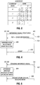
Fig. 2 illustrates an exemplary codebook containing codewords for encoding signals in corresponding beams of the wireless network, according to a preferred embodiment. -
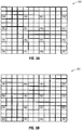
Figs. 3A-3B illustrate exemplary reference signal structures that each contains pilots coded according to different precoding matrix index values, according to a preferred embodiment. -
Fig. 4 is a flow diagram of a process of performing downlink beam selection according to a preferred embodiment. -
Fig. 5 is a flow diagram of a process of performing uplink beam selection according to a preferred embodiment. - In the following description, numerous details are set forth to provide an understanding of some embodiments. However, it will be understood by those skilled in the art that some embodiments may be practiced without these details and that numerous variations or modifications from the described embodiments may be possible.
-
Fig. 1 shows an exemplary wireless network in which a spatial division multiple access (SDMA) mechanism according to preferred embodiments is provided. The wireless network includes abase station 100 that includes an antenna array or other assembly (multi-beam antenna) 102 for producing multiple beams (spatial beams) 104, 106 in acorresponding cell sector 108. Although just twobeams Fig. 1 , it is noted that more than two beams can be provided in a cell sector in other embodiments. SDMA enables radio frequency (RF) resources (e.g., frequencies, time slots, etc.) to be reused in different geographic regions of a cell sector by transmitting different beams into the different geographic regions using multi-beam antennas. A "beam" (or "spatial beam") refers to a wireless signal (or wireless signals) that is (are) transmitted along a particular geographic path. A beam pattern refers to the coverage area of the beam. - A cell sector is one section of a cell of a cellular network. In alternative implementations, rather than providing multiple beams in a cell sector, it is noted that multiple beams can be provided in a cell. As used here, a "cell segment" can refer to either a cell sector or a cell. To provide SDMA, multiple beams are generated in such a cell segment.
- Although just one base station is depicted in
Fig. 1 , it is noted that a wireless network would typically include multiple base stations. In some implementations, the wireless network is a Long Term Evolution (LTE) wireless network as defined by the Third Generation Partnership Project (3GPP). In alternative implementations, other types of wireless networks can be employed. Note that reference to a "LTE wireless network" refers to a wireless network defined by current standards for LTE, or by subsequent standards that evolve from LTE. Moreover, even though reference is made to LTE wireless networks in the ensuing discussion, it is noted that techniques according to preferred embodiments can also be applied to non-LTE wireless networks. - A
mobile station 110 can communicate using one or both of thebeams cell sector 108, depending upon the position of themobile station 110 in the cell sector. As depicted, themobile station 110 is in a position to communicate usingbeam 106. Themobile station 110 can move to another location in thecell sector 108 to communicate usingbeam 104. Alternatively, themobile station 110 can move to a location that is in anoverlap region 105 between thebeams mobile station 110 is able to communicate using bothbeams - In an LTE wireless network, the
base station 100 includes an enhanced node B, which includes a base transceiver station that includes theantenna array 102. Thebase station 100 also includes a radio network controller that cooperates with the enhanced node B. The radio network controller and/or enhanced node B can perform one or more of the following tasks: radio resource management, mobility management for managing mobility of mobile stations, routing of traffic, and so forth. Note that one radio network controller can access multiple node Bs, or alternatively, a node B can be accessed by more than one radio access controller. - As depicted in
Fig. 1 , thebase station 100 includes one or more central processing units (CPUs) 122, which is (are) connected tostorage 124. Moreover, the base station includessoftware 126 that is executable on the CPU(s) 122 to perform tasks of thebase station 100, including tasks according to preferred embodiments to enable support for SDMA in the LTE wireless network. - The
base station 100 is connected to a serving and/or packet data network (PDN)gateway 112, which terminates the user plane interface toward the enhanced node B and assumes the responsibility for package routing and transfer towards an external network 114, which can be a packet data network such as the Internet or other type of network. - The arrangement depicted in
Fig. 1 is provided for purposes of example. In other implementations, other wireless network arrangements are used. - In accordance with preferred embodiments, to enable downlink beam selection, the
base station 100 is able to send different information sets on corresponding beams (e.g., 104, 106) in thecell sector 108 for receipt by mobile stations within thecell sector 108. Downlink beam selection refers to selection of one of thebeams 104, 106 (or bothbeams 104, 106) depending upon the location of the mobile station to perform communication of downlink data (from thebase station 100 to the mobile station). The downlink beam selection for a particular mobile station (e.g., 110) is performed at thebase station 100 in response to indications received from the particular mobile station, where the indications are generated by the particular mobile station depending upon which of the information sets was received by the mobile station. - For example, the
mobile station 110 located in a region corresponding tobeam 106 would receive the information set transmitted inbeam 106, but will not receive the information set transmitted inbeam 104. On the other hand, a mobile station located in a region corresponding tobeam 104 would receive the information set communicated inbeam 104, but would not receive the information set communicated inbeam 106. A mobile station located in anoverlap region 105 between thebeams beams - Depending on the information set(s) detected by the mobile station, the mobile station will send back a corresponding indication to the
base station 100. The indication sent by the mobile station will differ depending on which of the information set(s) is detected by the mobile station. Based on the indication received from the mobile station, thebase station 100 performs beam selection from among plural beams for communicating downlink data to the mobile station. The indication received by thebase station 100 from the mobile station enables thebase station 100 to identify the beam that the mobile station is able to receive in the downlink direction. - According to preferred embodiments, the SDMA operation supported by the LTE wireless network is transparent to the mobile station. In other words, changes do not have to be made to mobile stations in the LTE wireless network to provide SDMA support, which reduces costs associated with deploying SDMA. The mobile station is able to detect the information sets communicated by the base station-however, the mobile station does not have to recognize that the information sets were sent in different beams, and the mobile station does not have to be configured to identify which beam the mobile station is communicating with.
- In preferred embodiments, the information sets communicated in the
beams - In some implementations, each information set communicated in each of the
beams cell sector 108. Thus, for example, if thebase station 100 transmits two pilot signals in thecell sector 108, then both pilot signals would be communicated in each information set communicated in eachcorresponding beam beam 104 would receive an information set containing pilot signals subjected to a first coding (using a first codeword), while a mobile station in a region corresponding tobeam 106 would receive an information set with pilot signals subjected to a second, different coding (using a second codeword). -
Fig. 2 shows an exemplary codebook that has a number of entries containing exemplary codewords. The codebook is arranged as a matrix having rows corresponding to four codebook indexes (0, 1, 2, 3), and two columns corresponding to two ranks (1, 2). The arrangement ofFig. 2 is provided for purposes of example, as the actual data structure of the codebook may be different. There are four entries (containing four respective codewords) corresponding to rank 1 and three entries (containing three respective codewords) corresponding to rank 2. "Rank 2" indicates that a particular wireless channel used to communicate data between a base station and a mobile station is able to use two layers, which means that the current RF channel between the base station and the particular mobile station can support two layers (and in a preferred implementation) these two layers will utilize bothbeams rank 1" means that just a single layer can be used for the wireless channel that communicates data between the base station and mobile station. If just a single layer is enabled, then the data transmitted to a mobile station is transmitted in just one of thebeams rank 2 is possible when a mobile station is located in an overlap region, such asoverlap region 105, between multiple beams (e.g., 104, 106). - The entry in the codebook identified by codebook
index 0 andrank 1 has the following value,
- On the other hand, the codeword contained in the entry of the codebook identified by codebook
index 1 andrank 1 hasvalue 
- The codeword corresponding to the entry associated with
codebook index 2 andrank 1 hasvalue 
- The codewords associated with the
rank 2 entries in the codebook are interpreted similarly, except that the pilot signals subjected to rank 2 coding are communicated over two beams, rather than just one beam as with pilot signals subjected to rank 1 coding. -
Figs. 3A-3B depict two different information sets, in the form ofreference signal structures reference signal structures reference signal structures Fig. 3A shows a reference signal structure in which the coding applied to pilot signals (represented as R0 and R1) are subjected to coding applied by the codeword contained in the codebook entry corresponding to codebookindex 0 andrank 1.Fig. 3B shows a reference signal structure in which the coding applied to pilot signals (represented as R0 and R1) are subjected to coding applied by the codeword contained in the codebook entry corresponding to codebookindex 1 andrank 1. - The
reference signal structures reference signal structure 300 has a +1 phase (according to the codeword atcodebook index 0, rank 1), while pilot signal R1 inreference signal structure 302 has a -1 phase (according to the codeword atcodebook index 1, rank 1). The R0 pilot signal occupies the same positions in bothreference signal structures reference signal structures reference signal structures reference signal structures - The indication that is reported by the mobile station back to the
base station 100 depends upon which reference signal structure is detected by the mobile station. In other words, if a first information set is detected by the mobile station, then a first indication is sent. However, if a second information set is detected by the mobile station, then a second indication is sent. If a combination of the first and second information sets (e.g., reference signal structures corresponding to eitherbeam 1 or beam 2) are received by the mobile station, then depending on the relative strength of the two sets, either the beam corresponding to the stronger set will be indicated by the mobile station or if the signals are of comparable strength then a third indication may result that does not correspond to either beam.. - In some preferred embodiments, the indication reported by the mobile station is a precoding matrix index (PMI). In an exemplary implementation, a mobile station that is exclusively in a region corresponding to
beam 1, with no significant interference frombeam 2, will report a first PMI, such as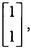
codebook index 0,rank 1. On the other hand, a mobile station that is located exclusively in beam 2 (with no significant interference from beam 1) will report the second PMI, such as
codebook index 1,rank 1. In some cases, the mobile station can report anotherrank 1 PMI, such as

other rank 1 PMI is reported, then that indicates that the mobile station can see more than one beam. In this scenario, a diversity mode is employed in which the same data is multiplexed using both beams (employing either time diversity, space diversity, block code diversity or some combination of these methods) to the mobile station. In one implementation, the diversity mode used is a spatial frequency block coding (SFBC) mode. A mobile station can see both beams if the mobile station is in an overlap region (e.g., 105 inFig. 1 ) between the two beams. - If the mobile station detects that an RF channel can support two layers, and if the mobile station is in the overlap region (e.g., 105) between two beams, then the mobile station can report a
rank 2 PMI, such as PMIs corresponding to one of the codewords depicted in the codebook ofFig. 2 . In such a scenario, the base station will use a MIMO (multiple input multiple output) mode, in which both beams are used for simultaneously communicating different data to the mobile station, to improve throughput. -
Fig. 4 is a message flow diagram of a procedure to perform downlink beam selection by thebase station 100. The base station transmits (at 402) reference signal structures in corresponding beams in a given cell sector. Depending on where the mobile station is located, the mobile station can receive one of the beams, or the other of the beams, or both of the beams (assuming that there are two beams). Note that in alternative implementations, more than two beams can be transmitted by the base station. - Based on the reference signal structures detected by the mobile station, the mobile station sends (at 404) a PMI back to the
base station 100. Note that the mobile station can also send other information back to the base station, where such other information can include metrics representing beam quality. For example, a metric representing beam quality can be in the form of a channel quality indicator (CQI). The other information transmitted by the mobile station back to the base station can also include rank information (e.g.,rank 1 or rank 2) to indicate the number of layers supported by an RF channel over which the mobile station is communicating. The PMI, CQI, and rank information can be sent by the mobile station to thebase station 100 in one control message, or in plural control messages. For example, the PMI, CQI, and rank information can be communicated in a physical uplink control channel (PUCCH), or in some other control channel. - Based on the received PMI and other information, the
base station 100 can perform (at 406) downlink beam selection. Beam selection can include the base station selecting one of the beams, or the other of the beams, or both beams, for communicating downlink data with the mobile station. The PMI informs thebase station 100 the beam(s) that the mobile station is able to see. The CQI information informs thebase station 100 of the quality of the beam(s) detected by the mobile station, and the rank information informs thebase station 100 of the number of layers supported by the current RF channel. Using the above information, thebase station 100 is able to select the beam(s) for use in transmitting downlink data. - Beam selection also involves selecting the mode in which the base station is to communicate downlink data with the mobile station, where the mode can be a single input multiple output (SIMO) mode (in which one beam is used for communicating with each mobile station-note that multiple beams can be used for communicating downlink data to multiple mobile stations). Another mode of operation is a diversity mode, or SFBC mode, in which the same data is sent in multiple beams but in different phases to improve communication performance and cell coverage improvement. Another possible mode is MIMO mode, in which different data is transmitted to a mobile station simultaneously on different beams to improve per-user throughput. Mode selection is also based on the PMI, CQI and rank information.
- Note that the beam and mode selection (406) can be performed by a downlink scheduler (part of
software 126 inFig. 1 ) in thebase station 100. - Based on the selected mode and beam selection performed at 406, the base station sends (at 408) a downlink scheduling grant message to the mobile station, where the grant message can contain a field to indicate the mode of operation (e.g., MIMO mode, SIMO mode, or SFBC mode). The grant message will also indicate which codeword that the mobile station is to use. For example, the grant message can contain a particular field that can have: (1) a first value to indicate SIMO mode with a first codeword applied to downlink data sent in the first beam, (2) a second value to indicate SIMO mode with a second codeword applied to downlink data in the second beam, (3) a third value to indicate SFBC mode to perform transmit diversity, and (4) a fourth value to indicate MIMO mode with a
corresponding rank 2 codeword. - The above has described a technique for enabling the
base station 100 to (1) identify, for downlink data communication, the beam that a mobile station is able to receive, and (2) select the beam(s) that the base station is to use for transmitting downlink data. - In preferred embodiments, to enable the base station to determine which beam the mobile station will be using for uplink data (from the mobile station to the base station 100), the mobile station sends an uplink reference signal. In one example, this uplink reference signal is referred to as a sounding reference signal. As depicted in
Fig. 5 , the mobile station sends (at 502) a sounding reference signal to thebase station 100. Thebase station 100 then determines (at 504) whether the mobile station transmitted the sounding reference signal in the first beam or second beam, so that the base station can select the appropriate beam to receive (at 506) uplink data from the mobile station. - The
base station 100 can include an uplink scheduler (part of software 126) to perform scheduling for communication of uplink data by the mobile stations in thecell sector 108. The uplink scheduler can perform the uplink beam selection either independently or jointly with the downlink scheduler. When the uplink and downlink schedulers work jointly, then the schedulers can confirm whether or not a mobile station is in a region of a beam. For example, if both the uplink and downlink schedulers select a particular beam for the mobile station, then that is an indication that the mobile station is definitely in the region corresponding to the particular beam. However, if the uplink and downlink schedulers select inconsistent beams for the mobile station, then the schedulers may have to perform further analysis to determine which of the beams is the correct one to select for both the uplink and downlink directions. Also, during handover between different base stations, both the uplink and downlink beam selections have to be considered. - In some exemplary embodiments, downlink control signals can be sent by the
base station 100 as follows. For example, synchronization signals such as a primary synchronization channel (P-SCH) and secondary synchronization channel (S-SCH) can be sent on bothbeams - Other downlink control signals can be sent on both
beams - Another downlink control channel is the PDCCH (physical downlink control channel). If the number of mobile stations in a cell sector is not large (e.g., less than some predefined threshold), SFBC diversity transmission can be used by the
base station 100 to send the PDCCH in both beams. However, if there are a relatively large number of mobile stations, the PDCCHs for different mobile stations can be sent in different beams, depending on the locations of the mobile stations. In one example, three groups of mobile stations located in a cell sector can be identified: (1) group 1: mobile stations in overlap region between two beams; (2) group 2: mobile stations in first beam area; and (3) group 3: mobile stations in second beam area. The first beam will be used by thebase station 100 to transmit PDCCHs to mobile stations ingroups base station 100 to transmit PDCCHs to mobile stations ingroups - Another downlink control signal that can be sent using SFBC diversity mode is the random access response message that is sent by the base station to the mobile station in response to a random access channel (RACH) from the mobile station. RACH is sent by the mobile station to establish a call or other communications session.
- Although reference is made to specific exemplary downlink channels in this discussion, it is noted that different implementations can use different control channels.
- In some exemplary embodiments, uplink control signals can be received by the
base station 100 as follows. The uplink random access channel (RACH) is received by the base station in both beams (so that no beam selection has to be performed). Also, the PUCCH can also be received by the base station in both beams, or the PUCCH can be received in either beam, where users in different beams can be assigned the same PUCCH resources, thus increasing PUCCH capacity (similar to uplink data). - Although reference is made to specific exemplary uplink channels in this discussion, it is noted that different implementations can use different control channels.
- In some embodiments, for communication of uplink data or control signaling, two mobile stations are assigned the same resource block (same combination of time slot and subcarrier) in two different beams. For the
base station 100 to be able to reliably receive the uplink data or control signaling in such a scenario, thebase station 100 is able to assign two orthogonal demodulation reference signals to the mobile stations. The demodulation reference signal sent by one mobile station will not be shifted; however, the demodulation reference signal sent by the other mobile station will have a half-length cyclic shift applied. The demodulation reference signal and application of cyclic shift is described in the 3GPP 36.211 Specification. The orthogonal demodulation reference signals associated with the uplink data and/or control signaling from the mobile stations will enable thebase station 100 to accurately determine the mutual RF interference or isolation of the mobile stations in the two beams. - The orthogonal demodulation reference signal to be used by each mobile station for uplink transmission is indicated by the base station in the uplink scheduling grant message. The grant message can include a parameter to indicate the cyclic shift to be applied to the uplink demodulation reference signal for multiuser-MIMO (MU-MIMO) mode. The parameter having a first value indicates no cyclic shift, whereas the parameter having a second value indicates a half length cyclic shift, to provide the orthogonal demodulation reference signals.
- Instructions of the software described above, such as
software 126 in thebase station 100 ofFig. 1 , can be executed on a processor. Software can also be executed by a processor in themobile station 110 ofFig. 1 . The processor includes microprocessors, microcontrollers, processor modules or subsystems (including one or more microprocessors or microcontrollers), or other control or computing devices. A "processor" can refer to a single component or to plural components. - Data and instructions (of the software) are stored in respective storage devices, which are implemented as one or more computer-readable or computer-usable storage media. The storage media include different forms of memory including semiconductor memory devices such as dynamic or static random access memories (DRAMs or SRAMs), erasable and programmable read-only memories (EPROMs), electrically erasable and programmable read-only memories (EEPROMs) and flash memories; magnetic disks such as fixed, floppy and removable disks; other magnetic media including tape; and optical media such as compact disks (CDs) or digital video disks (DVDs).
- In the foregoing description, numerous details are set forth to provide an understanding of the present invention. However, it will be understood by those skilled in the art that the present invention may be practiced without these details. While the invention has been disclosed with respect to a limited number of embodiments, those skilled in the art will appreciate numerous modifications and variations therefrom. It is intended that the appended claims cover such modifications and variations as fall within the true spirit and scope of the invention.
Examples are set out in the following list of numbered clauses. - 1. A method of providing space division multiple access in a wireless network, comprising:
- transmitting plural beams within a cell segment;
- sending different information sets in the corresponding plural beams, wherein one or more of the information sets are detectable by a mobile station depending upon a location of the mobile station in the cell segment;
- receiving an indication responsive to which of the different information sets is detected by the mobile station; and
- performing beam selection from among the plural beams according to the received indication.
- 2. The method of
clause 1, where receiving the indication comprises:- receiving a first indication if a first of the information sets but not a second of the information sets is detected by the mobile station;
- receiving a second indication if the second information set but not the first information set is detected by the mobile station; and
- receiving a third indication if both the first and second sets are detected by the mobile station.
- 3. The method of
clause 1, wherein receiving the indication comprises receiving a precoding matrix index. - 4. The method of
clause 1, wherein the transmitting, sending, receiving, and performing are performed by a base station in a Long Term Evolution (LTE) wireless network. - 5. The method of
clause 1, further comprising:- receiving, from the mobile station, one or more signal quality metrics associated with the corresponding plural beams,
- wherein performing the beam selection is also according to the one or more signal quality metrics.
- 6. The method of clause 5, wherein receiving the one or more signal quality metrics comprises receiving one or more channel quality indications (CQIs).
- 7. The method of
clause 1, wherein sending the different information sets comprises sending different reference signal structures, wherein each of the different reference signal structures has a same set of pilots. - 8. The method of clause 7, wherein the different reference signal structures employ different phases for at least one pilot of the sets of pilots.
- 9. The method of
clause 1, wherein performing the beam selection comprises performing downlink beam selection, the method further comprising:- receiving, by a base station, reference signals from the mobile station; and
- determining, based on the reference signals by the base station, a beam from among the plural beams to communicate uplink data.
- 10. The method of
clause 1, further comprising:- receiving rank information to indicate a number of layers supportable by a wireless channel; and
- selecting a mode of operation based on the indication and rank information.
- 11. The method of clause 10, wherein selecting the mode comprises selecting from among a single input multiple output (SIMO) mode, a diversity mode, and a multiple input multiple output (MIMO) mode.
- 12. The method of
clause 1, further comprising:- sending a message to the mobile station, wherein the message indicates an amount of cyclic shift to apply to a demodulation reference signal; and
- receiving the demodulation reference signal from the mobile station having the amount of cyclic shift applied.
- 13. The method of clause 12, wherein the amount of cyclic shift applied is none, the method further comprising:
sending a second message to a second mobile station, wherein the second message indicates a non-zero cyclic shift to be applied to a demodulation reference signal sent by the second mobile station. - 14. A base station comprising:
- an antenna assembly to generate plural beams to be communicated in a cell segment; and
- a processor to:
- transmit different information sets in respective beams to a mobile station in the cell sector, wherein the mobile station is able to detect one or more of the information sets depending upon a location of the mobile station in the cell sector;
- receive an indication responsive to which of the different information sets is detected by the mobile station; and
- select one or more beams from among the plural beams according to the received indication for communicating downlink data to the mobile station.
- 15. The base station of clause 14, wherein the processor is to further:
- receive rank information and beam quality metrics from the mobile station; and
- select a mode from among plural modes for communicating the downlink data.
- 16. The base station of clause 15, wherein the selected mode is one of a single input multiple output (SIMO) mode, diversity mode, and multiple input multiple output (MIMO) mode.
- 17. The base station of clause 14, wherein the processor is to further:
- receive a sounding reference signal from the mobile station; and
- determine which of the plural beams to use for communication of uplink data based on the received sounding reference signal.
- 18. The base station of clause 14, wherein the processor is to communicate certain control signals to the mobile station in diversity mode.
- 19. An article comprising at least one computer-readable storage medium containing instructions that when executed by a base station cause the base station to:
- cause transmission of plural beams within a cell segment;
- send different information sets in the corresponding plural beams, wherein one or more of the information sets are detectable by a mobile station depending upon a location of the mobile station in the cell segment;
- receive an indication responsive to which of the different information sets is detected by the mobile station; and
- perform beam selection from among the plural beams according to the received indication.
- 20. The article of clause 19, wherein the instructions when executed cause the base station to further select a mode for communicating data, wherein the selected mode is one of a single input multiple output (SIMO) mode, diversity mode, and multiple input multiple output (MIMO) mode.
Claims (10)
- A method of providing space division multiple access in a wireless network, comprising:transmitting plural beams (104, 106) within a cell segment;sending different information sets in the corresponding plural beams (104, 106), wherein one or more of the information sets are detectable by a mobile station (110) depending upon a location of the mobile station (110) in the cell segment;receiving an indication responsive to which of the different information sets is detected by the mobile station (110);receiving an uplink signal from the mobile station (110); determining a beam indicated by the received uplink signal; andperforming beam selection from among the plural beams (104, 106) according to the received indication and the determined beam.
- The method of claim 1, where receiving the indication comprises:receiving a first indication if a first of the information sets but not a second of the information sets is detected by the mobile station (110); andreceiving a second indication if the second information set but not the first information set is detected by the mobile station (110).
- The method of claim 1, wherein the transmitting, sending, receiving, and performing are performed by a base station (100) in a wireless network.
- The method of claim 1, further comprising:receiving, from the mobile station (110), one or more signal quality metrics associated with the corresponding plural beams (104, 106),wherein performing the beam selection is also according to the one or more signal quality metrics.
- The method of claim 1, wherein the indication comprises a metric representing quality of a beam received by the mobile station.
- The method of claim 5, wherein the metric is at least one of a Channel Quality Indicator (CQI), a Precoding Matric Indicator (PMI), and a rank information.
- The method of claim 1, wherein a transmission mode is selected based on the received indication.
- The method of claim 1, wherein the uplink signal is a sounding reference signal.
- Apparatus arranged to perform the method of any preceding claim.
- A computer readable storage medium carrying instructions for execution by a processor to cause the method of any of claims 1 to 8 to be performed.
Applications Claiming Priority (3)
| Application Number | Priority Date | Filing Date | Title |
|---|---|---|---|
| US95000707P | 2007-07-16 | 2007-07-16 | |
| EP08832255.7A EP2168401B1 (en) | 2007-07-16 | 2008-07-16 | Providing space division multiple access in a wireless network |
| PCT/IB2008/003365 WO2009037580A2 (en) | 2007-07-16 | 2008-07-16 | Providing space division multiple access in a wireless network |
Related Parent Applications (2)
| Application Number | Title | Priority Date | Filing Date |
|---|---|---|---|
| EP08832255.7A Division-Into EP2168401B1 (en) | 2007-07-16 | 2008-07-16 | Providing space division multiple access in a wireless network |
| EP08832255.7A Division EP2168401B1 (en) | 2007-07-16 | 2008-07-16 | Providing space division multiple access in a wireless network |
Publications (3)
| Publication Number | Publication Date |
|---|---|
| EP3493427A1 true EP3493427A1 (en) | 2019-06-05 |
| EP3493427B1 EP3493427B1 (en) | 2025-05-28 |
| EP3493427C0 EP3493427C0 (en) | 2025-05-28 |
Family
ID=40468505
Family Applications (2)
| Application Number | Title | Priority Date | Filing Date |
|---|---|---|---|
| EP08832255.7A Active EP2168401B1 (en) | 2007-07-16 | 2008-07-16 | Providing space division multiple access in a wireless network |
| EP19152460.2A Active EP3493427B1 (en) | 2007-07-16 | 2008-07-16 | Providing space division multiple access in a wireless network |
Family Applications Before (1)
| Application Number | Title | Priority Date | Filing Date |
|---|---|---|---|
| EP08832255.7A Active EP2168401B1 (en) | 2007-07-16 | 2008-07-16 | Providing space division multiple access in a wireless network |
Country Status (7)
| Country | Link |
|---|---|
| US (1) | US8982779B2 (en) |
| EP (2) | EP2168401B1 (en) |
| JP (1) | JP5277246B2 (en) |
| KR (1) | KR20100049025A (en) |
| CN (1) | CN101868988B (en) |
| CA (1) | CA2690990C (en) |
| WO (1) | WO2009037580A2 (en) |
Families Citing this family (101)
| Publication number | Priority date | Publication date | Assignee | Title |
|---|---|---|---|---|
| AR067232A1 (en) * | 2007-03-19 | 2009-10-07 | Interdigital Tech Corp | A VECTOR SWITCH AND FREQUENCY SWITCH TRANSMITTER OF COMBINED DIVERSITY PRECODIFIER FOR A SYNCHRONIZATION OF SECONDARY CHANNEL IN EVOLVED UTRA |
| KR101481201B1 (en) * | 2007-07-30 | 2015-01-21 | 삼성전자주식회사 | Method and system for transmitting and receiving different signal types in communication systems |
| US8630184B2 (en) * | 2007-08-15 | 2014-01-14 | Qualcomm Incorporated | Uplink control channel format |
| EP3432504B1 (en) * | 2007-10-30 | 2021-06-23 | Nokia Technologies Oy | Methods, apparatuses, system and related computer program product for resource allocation |
| CN104868980B (en) | 2008-02-04 | 2019-06-21 | 诺基亚通信公司 | Cyclic shift is mapped to the channel indexes for being used for ACK/NACK resource allocation |
| US8274930B2 (en) * | 2008-03-10 | 2012-09-25 | Mitsubishi Electric Research Laboratories, Inc. | Analog beamforming to reduce interference in WiMAX networks |
| KR101749845B1 (en) * | 2008-04-29 | 2017-06-21 | 애플 인크. | Improved performance for a multiple antenna beamforming cellular network |
| EP2306659B1 (en) | 2008-07-22 | 2018-01-24 | Lg Electronics Inc. | Method for allocating phich in a system using su-mimo with multiple codewords in uplink |
| KR20100019948A (en) * | 2008-08-11 | 2010-02-19 | 엘지전자 주식회사 | Method of transmitting data using spatial multiplexing |
| US8428018B2 (en) * | 2008-09-26 | 2013-04-23 | Lg Electronics Inc. | Method of transmitting reference signals in a wireless communication having multiple antennas |
| KR101673497B1 (en) * | 2009-01-05 | 2016-11-07 | 마벨 월드 트레이드 리미티드 | Precoding codebooks for mimo communication systems |
| US8385441B2 (en) * | 2009-01-06 | 2013-02-26 | Marvell World Trade Ltd. | Efficient MIMO transmission schemes |
| US8699528B2 (en) | 2009-02-27 | 2014-04-15 | Marvell World Trade Ltd. | Systems and methods for communication using dedicated reference signal (DRS) |
| US8238483B2 (en) | 2009-02-27 | 2012-08-07 | Marvell World Trade Ltd. | Signaling of dedicated reference signal (DRS) precoding granularity |
| US8693429B2 (en) | 2009-03-31 | 2014-04-08 | Qualcomm Incorporated | Methods and apparatus for generation and use of reference signals in a communications system |
| US8457236B2 (en) * | 2009-04-06 | 2013-06-04 | Marvell World Trade Ltd. | Feedback strategies for multi-user MIMO communication systems |
| US8543063B2 (en) * | 2009-04-21 | 2013-09-24 | Marvell World Trade Ltd. | Multi-point opportunistic beamforming with selective beam attenuation |
| US8675794B1 (en) | 2009-10-13 | 2014-03-18 | Marvell International Ltd. | Efficient estimation of feedback for modulation and coding scheme (MCS) selection |
| US8917796B1 (en) | 2009-10-19 | 2014-12-23 | Marvell International Ltd. | Transmission-mode-aware rate matching in MIMO signal generation |
| WO2011055238A1 (en) | 2009-11-09 | 2011-05-12 | Marvell World Trade Ltd | Asymmetrical feedback for coordinated transmission systems |
| JP5637486B2 (en) | 2009-12-17 | 2014-12-10 | マーベル ワールド トレード リミテッド | MIMO feedback scheme for cross-polarized antennas |
| JP5258002B2 (en) | 2010-02-10 | 2013-08-07 | マーベル ワールド トレード リミテッド | Device, mobile communication terminal, chipset, and method in MIMO communication system |
| US8687741B1 (en) | 2010-03-29 | 2014-04-01 | Marvell International Ltd. | Scoring hypotheses in LTE cell search |
| CN102244566B (en) * | 2010-05-11 | 2014-03-12 | 中兴通讯股份有限公司 | Downlink transmission method and base station for multiple input and multiple output (MIMO) system |
| US9014301B2 (en) * | 2010-05-14 | 2015-04-21 | Qualcomm Incorporated | Dedicated reference signal |
| EP2584810A1 (en) * | 2010-06-21 | 2013-04-24 | Fujitsu Limited | Method for reference signal transmission, method for channel quality estimation, mobile station, base station, and wireless communication system |
| US8838159B2 (en) * | 2010-06-28 | 2014-09-16 | Lg Electronics Inc. | Method and apparatus for transmitting reference signal in multi-node system |
| JP5438219B2 (en) * | 2010-07-15 | 2014-03-12 | 京セラ株式会社 | Wireless communication system, mobile station, base station, and wireless communication method |
| EP2600580B1 (en) * | 2010-07-26 | 2018-04-18 | LG Electronics Inc. | Method and device for transmitting control information |
| US8615052B2 (en) | 2010-10-06 | 2013-12-24 | Marvell World Trade Ltd. | Enhanced channel feedback for multi-user MIMO |
| JP2012100254A (en) | 2010-10-06 | 2012-05-24 | Marvell World Trade Ltd | Codebook subsampling for pucch feedback |
| WO2012063980A1 (en) * | 2010-11-08 | 2012-05-18 | Pantech Co.,Ltd. | Terminal and base station, method thereof in wireless communication system |
| CA2803906C (en) * | 2010-12-10 | 2018-10-30 | Panasonic Corporation | Signal generation method and signal generation device |
| SG191116A1 (en) | 2010-12-22 | 2013-07-31 | Nokia Siemens Networks Oy | Allocation of resources |
| US9048970B1 (en) | 2011-01-14 | 2015-06-02 | Marvell International Ltd. | Feedback for cooperative multipoint transmission systems |
| US8861391B1 (en) | 2011-03-02 | 2014-10-14 | Marvell International Ltd. | Channel feedback for TDM scheduling in heterogeneous networks having multiple cell classes |
| WO2012131612A1 (en) | 2011-03-31 | 2012-10-04 | Marvell World Trade Ltd. | Channel feedback for cooperative multipoint transmission |
| CN107104716B (en) | 2011-04-19 | 2020-10-02 | 太阳专利托管公司 | Signal generation method and device, and signal processing method and device |
| KR101839386B1 (en) | 2011-08-12 | 2018-03-16 | 삼성전자주식회사 | Apparatus and method for adaptively beam-forming in wireless communication system |
| EP2747304A4 (en) * | 2011-08-15 | 2015-02-18 | Ntt Docomo Inc | WIRELESS BASE STATION, USER TERMINAL, WIRELESS COMMUNICATION SYSTEM, AND WIRELESS COMMUNICATION METHOD |
| KR101828836B1 (en) * | 2011-08-23 | 2018-02-13 | 삼성전자주식회사 | Apparatus and method for scheduling using beam scanning in beamformed wireless communication system |
| KR20130028397A (en) | 2011-09-09 | 2013-03-19 | 삼성전자주식회사 | Apparatus and method for synchronizing and obtaining system information in wireless communication system |
| US9014733B2 (en) * | 2011-09-16 | 2015-04-21 | Samsung Electronics Co., Ltd. | Method and apparatus for beam allocation in wireless communication system |
| KR101828837B1 (en) * | 2011-09-29 | 2018-03-30 | 삼성전자주식회사 | Method and apparatus for short handover latency in wireless communication system using beam forming |
| US8923427B2 (en) | 2011-11-07 | 2014-12-30 | Marvell World Trade Ltd. | Codebook sub-sampling for frequency-selective precoding feedback |
| US9020058B2 (en) | 2011-11-07 | 2015-04-28 | Marvell World Trade Ltd. | Precoding feedback for cross-polarized antennas based on signal-component magnitude difference |
| US9031597B2 (en) | 2011-11-10 | 2015-05-12 | Marvell World Trade Ltd. | Differential CQI encoding for cooperative multipoint feedback |
| US20130128821A1 (en) * | 2011-11-18 | 2013-05-23 | Nokia Siemens Networks Oy | Demodulation Reference Signal Arrangement For Uplink Coordinated Multi-Point Reception |
| US9220087B1 (en) | 2011-12-08 | 2015-12-22 | Marvell International Ltd. | Dynamic point selection with combined PUCCH/PUSCH feedback |
| KR101930355B1 (en) * | 2011-12-23 | 2018-12-20 | 한국전자통신연구원 | Communication system for determining data transmitting scheme according to channel state |
| US8902842B1 (en) | 2012-01-11 | 2014-12-02 | Marvell International Ltd | Control signaling and resource mapping for coordinated transmission |
| US9414371B2 (en) * | 2012-04-16 | 2016-08-09 | Samsung Electronics Co., Ltd. | Hierarchical channel sounding and channel state information feedback in massive MIMO systems |
| KR20150009980A (en) | 2012-04-27 | 2015-01-27 | 마벨 월드 트레이드 리미티드 | Coordinated multipoint (comp) communication between base-stations and mobile communication terminals |
| US20130286960A1 (en) * | 2012-04-30 | 2013-10-31 | Samsung Electronics Co., Ltd | Apparatus and method for control channel beam management in a wireless system with a large number of antennas |
| US9351288B2 (en) * | 2012-06-05 | 2016-05-24 | Samsung Electronics Co., Ltd. | Uplink channel sounding and channel state information estimation in mobile communication systems with multiple antennas |
| US9144082B2 (en) * | 2012-06-13 | 2015-09-22 | All Purpose Networks LLC | Locating and tracking user equipment in the RF beam areas of an LTE wireless system employing agile beam forming techniques |
| US9144075B2 (en) | 2012-06-13 | 2015-09-22 | All Purpose Networks LLC | Baseband data transmission and reception in an LTE wireless base station employing periodically scanning RF beam forming techniques |
| US9882950B2 (en) | 2012-06-13 | 2018-01-30 | All Purpose Networks LLC | Methods and systems of an all purpose broadband network |
| US9084143B2 (en) | 2012-06-13 | 2015-07-14 | All Purpose Networks LLC | Network migration queuing service in a wireless network |
| US9179354B2 (en) | 2012-06-13 | 2015-11-03 | All Purpose Networks LLC | Efficient delivery of real-time synchronous services over a wireless network |
| US9131385B2 (en) | 2012-06-13 | 2015-09-08 | All Purpose Networks LLC | Wireless network based sensor data collection, processing, storage, and distribution |
| US9503927B2 (en) | 2012-06-13 | 2016-11-22 | All Purpose Networks LLC | Multiple-use wireless network |
| US9094803B2 (en) | 2012-06-13 | 2015-07-28 | All Purpose Networks LLC | Wireless network based sensor data collection, processing, storage, and distribution |
| US8565689B1 (en) | 2012-06-13 | 2013-10-22 | All Purpose Networks LLC | Optimized broadband wireless network performance through base station application server |
| US9179392B2 (en) | 2012-06-13 | 2015-11-03 | All Purpose Networks LLC | Efficient delivery of real-time asynchronous services over a wireless network |
| US9137675B2 (en) | 2012-06-13 | 2015-09-15 | All Purpose Networks LLC | Operational constraints in LTE TDD systems using RF agile beam forming techniques |
| US9219541B2 (en) | 2012-06-13 | 2015-12-22 | All Purpose Networks LLC | Baseband data transmission and reception in an LTE wireless base station employing periodically scanning RF beam forming techniques |
| US9107094B2 (en) | 2012-06-13 | 2015-08-11 | All Purpose Networks LLC | Methods and systems of an all purpose broadband network |
| US9084155B2 (en) | 2012-06-13 | 2015-07-14 | All Purpose Networks LLC | Optimized broadband wireless network performance through base station application server |
| US9179352B2 (en) | 2012-06-13 | 2015-11-03 | All Purpose Networks LLC | Efficient delivery of real-time synchronous services over a wireless network |
| US9125064B2 (en) | 2012-06-13 | 2015-09-01 | All Purpose Networks LLC | Efficient reduction of inter-cell interference using RF agile beam forming techniques |
| US9125123B2 (en) | 2012-06-13 | 2015-09-01 | All Purpose Networks LLC | Efficient delivery of real-time asynchronous services over a wireless network |
| KR101995798B1 (en) | 2012-07-03 | 2019-07-03 | 삼성전자주식회사 | Device and method for random access in a wireless communication system using beamformig |
| USRE49452E1 (en) * | 2012-10-24 | 2023-03-07 | Samsung Electronics Co., Ltd | Method and apparatus for transmitting and receiving common channel information in wireless communication system |
| KR20140056561A (en) * | 2012-10-29 | 2014-05-12 | 한국전자통신연구원 | Method for operation of terminal and base-statin in cellular telecommunication system operating multiple beams |
| US9497047B2 (en) * | 2013-07-02 | 2016-11-15 | Samsung Electronics Co., Ltd. | Methods and apparatus for sounding channel operation in millimeter wave communication systems |
| EP2999253B1 (en) | 2013-07-23 | 2017-11-15 | Huawei Technologies Co., Ltd. | Data transmission method and apparatus |
| HK1223459A1 (en) * | 2013-09-05 | 2017-07-28 | 英特尔公司 | Adaptive sectorization of a spational region for parallel multi-user transmissions |
| JP2016540422A (en) * | 2013-12-12 | 2016-12-22 | インテル・コーポレーション | User equipment and method for cell association and beamforming training with a millimeter cell capable small cell |
| CN104955061A (en) * | 2014-03-28 | 2015-09-30 | 华为技术有限公司 | Wave beam selection method and base station |
| CN113543361B (en) * | 2014-04-30 | 2024-07-09 | 株式会社Ntt都科摩 | Terminal, base station, system and communication method |
| US9231676B2 (en) * | 2014-05-12 | 2016-01-05 | Nokia Solutions And Networks Oy | Low effort massive MIMO antenna arrays and their use |
| EP3214782B1 (en) * | 2014-11-25 | 2019-11-13 | Huawei Technologies Co., Ltd. | Method and apparatus for generating pilot frequency signal |
| JP2018518091A (en) | 2015-04-21 | 2018-07-05 | テレフオンアクチーボラゲット エルエム エリクソン(パブル) | Method and apparatus for monitoring radio link quality |
| WO2017006470A1 (en) * | 2015-07-08 | 2017-01-12 | 三菱電機株式会社 | Communication device and beam selection method |
| WO2017146765A1 (en) * | 2016-02-25 | 2017-08-31 | Intel IP Corporation | System and method for channel quality reporting |
| US10122559B2 (en) * | 2016-03-21 | 2018-11-06 | Qualcomm Incorporated | Uplink channel quality measurement using a subframe with high-intensity reference signal bursts |
| CN109417405A (en) * | 2016-09-30 | 2019-03-01 | Oppo广东移动通信有限公司 | Method and device for data transmission |
| CN108135030B (en) * | 2016-09-30 | 2020-10-23 | 华为技术有限公司 | Indication method and device for transmitting physical control channel |
| CA3042370A1 (en) * | 2016-11-01 | 2018-05-11 | Ntt Docomo, Inc. | Apparatus and radio communication method |
| US9979458B1 (en) | 2016-11-18 | 2018-05-22 | Nokia Solutions And Networks Oy | Precoder design for combining high-end RF with constrained RF of massive MIMO antennas |
| CN110073606B (en) | 2016-12-13 | 2021-01-08 | Oppo广东移动通信有限公司 | Signal transmission method, terminal device, network device and readable storage medium |
| US10568092B2 (en) * | 2017-02-17 | 2020-02-18 | Qualcomm Incorporated | Scheduling and/or scheduling configuration |
| JP7203357B2 (en) * | 2017-07-24 | 2023-01-13 | パナソニックIpマネジメント株式会社 | Transmitter and transmission method |
| JP6817910B2 (en) * | 2017-08-10 | 2021-01-20 | ノキア ソリューションズ アンド ネットワークス オサケユキチュア | Resource allocation |
| WO2020101747A1 (en) | 2018-01-08 | 2020-05-22 | All Purpose Networks, Inc. | Publish-subscribe broker network overlay system |
| EP3662370B1 (en) | 2018-01-08 | 2023-12-27 | All Purpose Networks, Inc. | Internet of things system with efficient and secure communications network |
| WO2020000308A1 (en) * | 2018-06-28 | 2020-01-02 | Apple Inc. | Beam failure recovery using contention based random access |
| EP3833088A4 (en) * | 2018-07-31 | 2021-08-11 | Fujitsu Limited | BASE STATION, MOBILE STATION, COMMUNICATION SYSTEM AND COMMUNICATION PROCESS |
| US11711793B2 (en) * | 2019-06-26 | 2023-07-25 | Qualcomm Incorporated | Beam selection for initiating random access during conditional handover execution |
| WO2025041209A1 (en) * | 2023-08-18 | 2025-02-27 | 株式会社Nttドコモ | Wireless device and control method |
Citations (5)
| Publication number | Priority date | Publication date | Assignee | Title |
|---|---|---|---|---|
| US20040214606A1 (en) * | 2003-04-25 | 2004-10-28 | Risto Wichman | Communication on multiple beams between stations |
| WO2006070478A1 (en) * | 2004-12-28 | 2006-07-06 | Fujitsu Limited | Wireless communication system |
| US20060233131A1 (en) * | 2005-04-19 | 2006-10-19 | Qualcomm Incorporated | Channel quality reporting for adaptive sectorization |
| US20070099578A1 (en) * | 2005-10-28 | 2007-05-03 | Kathryn Adeney | Pre-coded diversity forward channel transmission system for wireless communications systems supporting multiple MIMO transmission modes |
| US20070160156A1 (en) * | 2006-01-09 | 2007-07-12 | Ezer Melzer | Wireless communication device employing interference-sensitive mode selection and associated methods |
Family Cites Families (19)
| Publication number | Priority date | Publication date | Assignee | Title |
|---|---|---|---|---|
| DE69712790T2 (en) * | 1997-02-13 | 2004-08-19 | Nokia Corp. | METHOD AND DEVICE FOR RADIO RADIO TRANSMISSION |
| FI105063B (en) * | 1997-05-16 | 2000-05-31 | Nokia Networks Oy | Procedure for determining the direction of transmission and radio system |
| US6823021B1 (en) * | 2000-10-27 | 2004-11-23 | Greenwich Technologies Associates | Method and apparatus for space division multiple access receiver |
| US6701165B1 (en) * | 2000-06-21 | 2004-03-02 | Agere Systems Inc. | Method and apparatus for reducing interference in non-stationary subscriber radio units using flexible beam selection |
| US6850741B2 (en) | 2002-04-04 | 2005-02-01 | Agency For Science, Technology And Research | Method for selecting switched orthogonal beams for downlink diversity transmission |
| US7346365B1 (en) * | 2002-04-16 | 2008-03-18 | Faulkner Interstices Llc | Smart antenna system and method |
| US7529525B1 (en) * | 2002-04-16 | 2009-05-05 | Faulkner Interstices Llc | Method and apparatus for collecting information for use in a smart antenna system |
| TWI258940B (en) * | 2002-05-13 | 2006-07-21 | Interdigital Tech Corp | Resource allocation to users in slotted code division multiple access systems using beans |
| US7826471B2 (en) * | 2003-03-11 | 2010-11-02 | Nortel Networks Limited | Multi-beam cellular communication system |
| US7302238B2 (en) * | 2003-04-25 | 2007-11-27 | Samsung Electronics Co., Ltd. | Transmit diversity system, method and computer program product |
| WO2005107121A1 (en) * | 2004-04-28 | 2005-11-10 | Samsung Electronics Co., Ltd. | Method and apparatus for generating preamble sequence for adaptive antenna system in orthogonal frequency division multiple access communication system |
| KR20060081194A (en) * | 2005-01-07 | 2006-07-12 | 삼성전자주식회사 | Sector Construction Apparatus and Method in a Multi-antenna System |
| KR100950644B1 (en) * | 2005-03-04 | 2010-04-01 | 삼성전자주식회사 | Feedback method of multi-user multi-input / output system |
| US8144666B2 (en) * | 2005-05-13 | 2012-03-27 | Rockstar Bidco Lp | Downlink beamforming for broadband wireless networks |
| US9136974B2 (en) | 2005-08-30 | 2015-09-15 | Qualcomm Incorporated | Precoding and SDMA support |
| BRPI0617861A2 (en) | 2005-10-28 | 2012-04-17 | Matsushita Electric Industrial Co., Ltd | transmitting device, receiving device, transmission method, receiving method and wireless communication system |
| KR100996023B1 (en) * | 2005-10-31 | 2010-11-22 | 삼성전자주식회사 | Apparatus and method for data transmission and reception in a multi-antenna communication system |
| KR100735373B1 (en) * | 2006-02-06 | 2007-07-04 | 삼성전자주식회사 | Method and system for data transmission in communication system |
| CN101529788B (en) * | 2006-11-01 | 2014-04-16 | 高通股份有限公司 | Method and apparatus for hybrid FDM-CDM architecture for single carrier based control channel |
-
2008
- 2008-07-16 CN CN200880024775.5A patent/CN101868988B/en active Active
- 2008-07-16 EP EP08832255.7A patent/EP2168401B1/en active Active
- 2008-07-16 WO PCT/IB2008/003365 patent/WO2009037580A2/en not_active Ceased
- 2008-07-16 US US12/602,721 patent/US8982779B2/en active Active
- 2008-07-16 EP EP19152460.2A patent/EP3493427B1/en active Active
- 2008-07-16 KR KR1020107000975A patent/KR20100049025A/en not_active Withdrawn
- 2008-07-16 JP JP2010516614A patent/JP5277246B2/en active Active
- 2008-07-16 CA CA2690990A patent/CA2690990C/en active Active
Patent Citations (6)
| Publication number | Priority date | Publication date | Assignee | Title |
|---|---|---|---|---|
| US20040214606A1 (en) * | 2003-04-25 | 2004-10-28 | Risto Wichman | Communication on multiple beams between stations |
| WO2006070478A1 (en) * | 2004-12-28 | 2006-07-06 | Fujitsu Limited | Wireless communication system |
| EP1833186A1 (en) * | 2004-12-28 | 2007-09-12 | Fujitsu Ltd. | Wireless communication system |
| US20060233131A1 (en) * | 2005-04-19 | 2006-10-19 | Qualcomm Incorporated | Channel quality reporting for adaptive sectorization |
| US20070099578A1 (en) * | 2005-10-28 | 2007-05-03 | Kathryn Adeney | Pre-coded diversity forward channel transmission system for wireless communications systems supporting multiple MIMO transmission modes |
| US20070160156A1 (en) * | 2006-01-09 | 2007-07-12 | Ezer Melzer | Wireless communication device employing interference-sensitive mode selection and associated methods |
Also Published As
| Publication number | Publication date |
|---|---|
| EP2168401B1 (en) | 2019-05-08 |
| KR20100049025A (en) | 2010-05-11 |
| US20100173639A1 (en) | 2010-07-08 |
| CA2690990A1 (en) | 2009-03-26 |
| WO2009037580A2 (en) | 2009-03-26 |
| WO2009037580A3 (en) | 2010-04-29 |
| EP2168401A4 (en) | 2017-03-29 |
| US8982779B2 (en) | 2015-03-17 |
| JP5277246B2 (en) | 2013-08-28 |
| EP2168401A2 (en) | 2010-03-31 |
| EP3493427B1 (en) | 2025-05-28 |
| CA2690990C (en) | 2016-08-23 |
| EP3493427C0 (en) | 2025-05-28 |
| CN101868988A (en) | 2010-10-20 |
| JP2010534020A (en) | 2010-10-28 |
| CN101868988B (en) | 2014-09-24 |
Similar Documents
| Publication | Publication Date | Title |
|---|---|---|
| US8982779B2 (en) | Providing space division multiple access in a wireless network | |
| US11637667B2 (en) | Method and apparatus for transmitting and receiving uplink signal, storage medium, and electronic device | |
| CN108260217B (en) | Information transmission method, device and communication node | |
| US20200245166A1 (en) | Method and device for supporting beam-based cooperative communication in wireless communication system | |
| US11575424B2 (en) | UE recommended CSI settings | |
| US8838164B2 (en) | Method for transmitting feedback information in CoMP, terminal for performing same, method for generating channel state information and base station apparatus for performing same | |
| US10205498B2 (en) | User equipment and codebook search method for 4Tx dual codebook (ran1) | |
| US20150049692A1 (en) | Channel state information feedback method and user equipment | |
| EP2848031B1 (en) | Channel quality reporting in a communications system | |
| US20130286881A1 (en) | Channel state information feedback method and user equipment | |
| CN113923679A (en) | System and method for communication beam recovery | |
| CN110212958A (en) | Channel information feedback method and device in a kind of mobile communication system | |
| EP2206381A2 (en) | Rank adaptation for an open loop multi-antenna mode of wireless communication | |
| KR20110010538A (en) | How to transmit / receive COMP reference signal | |
| US20110077040A1 (en) | Including feedback information regarding an individual subband of a wireless channel | |
| CN107888255B (en) | Method, device and system for transmitting uplink reference signal, base station and terminal | |
| WO2017167156A1 (en) | Dmrs transmission method and device | |
| EP3455960B1 (en) | Method and first radio node for communicating data using hierarchical codebooks and multi-stage precoder selection. | |
| KR20150121185A (en) | Mobile station, base station, and communication control method | |
| WO2021064684A1 (en) | Virtual multi-transmission reception point/panel transmission for urllc | |
| US20240260028A1 (en) | Network node, user equipment and methods in a wireless communications network |
Legal Events
| Date | Code | Title | Description |
|---|---|---|---|
| PUAI | Public reference made under article 153(3) epc to a published international application that has entered the european phase |
Free format text: ORIGINAL CODE: 0009012 |
|
| STAA | Information on the status of an ep patent application or granted ep patent |
Free format text: STATUS: THE APPLICATION HAS BEEN PUBLISHED |
|
| AC | Divisional application: reference to earlier application |
Ref document number: 2168401 Country of ref document: EP Kind code of ref document: P |
|
| AK | Designated contracting states |
Kind code of ref document: A1 Designated state(s): AT BE BG CH CY CZ DE DK EE ES FI FR GB GR HR HU IE IS IT LI LT LU LV MC MT NL NO PL PT RO SE SI SK TR |
|
| STAA | Information on the status of an ep patent application or granted ep patent |
Free format text: STATUS: REQUEST FOR EXAMINATION WAS MADE |
|
| 17P | Request for examination filed |
Effective date: 20191205 |
|
| RBV | Designated contracting states (corrected) |
Designated state(s): AT BE BG CH CY CZ DE DK EE ES FI FR GB GR HR HU IE IS IT LI LT LU LV MC MT NL NO PL PT RO SE SI SK TR |
|
| STAA | Information on the status of an ep patent application or granted ep patent |
Free format text: STATUS: EXAMINATION IS IN PROGRESS |
|
| 17Q | First examination report despatched |
Effective date: 20200910 |
|
| GRAP | Despatch of communication of intention to grant a patent |
Free format text: ORIGINAL CODE: EPIDOSNIGR1 |
|
| STAA | Information on the status of an ep patent application or granted ep patent |
Free format text: STATUS: GRANT OF PATENT IS INTENDED |
|
| RIC1 | Information provided on ipc code assigned before grant |
Ipc: H04W 74/00 20090101ALN20241127BHEP Ipc: H04B 7/06 20060101ALI20241127BHEP Ipc: H04B 7/08 20060101AFI20241127BHEP |
|
| INTG | Intention to grant announced |
Effective date: 20241206 |
|
| RAP1 | Party data changed (applicant data changed or rights of an application transferred) |
Owner name: MALIKIE INNOVATIONS LIMITED |
|
| GRAS | Grant fee paid |
Free format text: ORIGINAL CODE: EPIDOSNIGR3 |
|
| GRAA | (expected) grant |
Free format text: ORIGINAL CODE: 0009210 |
|
| STAA | Information on the status of an ep patent application or granted ep patent |
Free format text: STATUS: THE PATENT HAS BEEN GRANTED |
|
| AC | Divisional application: reference to earlier application |
Ref document number: 2168401 Country of ref document: EP Kind code of ref document: P |
|
| AK | Designated contracting states |
Kind code of ref document: B1 Designated state(s): AT BE BG CH CY CZ DE DK EE ES FI FR GB GR HR HU IE IS IT LI LT LU LV MC MT NL NO PL PT RO SE SI SK TR |
|
| REG | Reference to a national code |
Ref country code: GB Ref legal event code: FG4D |
|
| REG | Reference to a national code |
Ref country code: CH Ref legal event code: EP |
|
| REG | Reference to a national code |
Ref country code: DE Ref legal event code: R096 Ref document number: 602008065209 Country of ref document: DE |
|
| REG | Reference to a national code |
Ref country code: IE Ref legal event code: FG4D |
|
| U01 | Request for unitary effect filed |
Effective date: 20250625 |
|
| U07 | Unitary effect registered |
Designated state(s): AT BE BG DE DK EE FI FR IT LT LU LV MT NL PT RO SE SI Effective date: 20250702 |
|
| U20 | Renewal fee for the european patent with unitary effect paid |
Year of fee payment: 18 Effective date: 20250825 |
|
| PG25 | Lapsed in a contracting state [announced via postgrant information from national office to epo] |
Ref country code: ES Free format text: LAPSE BECAUSE OF FAILURE TO SUBMIT A TRANSLATION OF THE DESCRIPTION OR TO PAY THE FEE WITHIN THE PRESCRIBED TIME-LIMIT Effective date: 20250528 |
|
| PG25 | Lapsed in a contracting state [announced via postgrant information from national office to epo] |
Ref country code: GR Free format text: LAPSE BECAUSE OF FAILURE TO SUBMIT A TRANSLATION OF THE DESCRIPTION OR TO PAY THE FEE WITHIN THE PRESCRIBED TIME-LIMIT Effective date: 20250829 Ref country code: NO Free format text: LAPSE BECAUSE OF FAILURE TO SUBMIT A TRANSLATION OF THE DESCRIPTION OR TO PAY THE FEE WITHIN THE PRESCRIBED TIME-LIMIT Effective date: 20250828 |
|
| PG25 | Lapsed in a contracting state [announced via postgrant information from national office to epo] |
Ref country code: PL Free format text: LAPSE BECAUSE OF FAILURE TO SUBMIT A TRANSLATION OF THE DESCRIPTION OR TO PAY THE FEE WITHIN THE PRESCRIBED TIME-LIMIT Effective date: 20250528 |
|
| PGFP | Annual fee paid to national office [announced via postgrant information from national office to epo] |
Ref country code: GB Payment date: 20250801 Year of fee payment: 18 |
|
| PG25 | Lapsed in a contracting state [announced via postgrant information from national office to epo] |
Ref country code: HR Free format text: LAPSE BECAUSE OF FAILURE TO SUBMIT A TRANSLATION OF THE DESCRIPTION OR TO PAY THE FEE WITHIN THE PRESCRIBED TIME-LIMIT Effective date: 20250528 |
|
| PG25 | Lapsed in a contracting state [announced via postgrant information from national office to epo] |
Ref country code: IS Free format text: LAPSE BECAUSE OF FAILURE TO SUBMIT A TRANSLATION OF THE DESCRIPTION OR TO PAY THE FEE WITHIN THE PRESCRIBED TIME-LIMIT Effective date: 20250928 |
|
| PG25 | Lapsed in a contracting state [announced via postgrant information from national office to epo] |
Ref country code: CZ Free format text: LAPSE BECAUSE OF FAILURE TO SUBMIT A TRANSLATION OF THE DESCRIPTION OR TO PAY THE FEE WITHIN THE PRESCRIBED TIME-LIMIT Effective date: 20250528 |
|
| PG25 | Lapsed in a contracting state [announced via postgrant information from national office to epo] |
Ref country code: SK Free format text: LAPSE BECAUSE OF FAILURE TO SUBMIT A TRANSLATION OF THE DESCRIPTION OR TO PAY THE FEE WITHIN THE PRESCRIBED TIME-LIMIT Effective date: 20250528 |
|
| REG | Reference to a national code |
Ref country code: CH Ref legal event code: H13 Free format text: ST27 STATUS EVENT CODE: U-0-0-H10-H13 (AS PROVIDED BY THE NATIONAL OFFICE) Effective date: 20260224 |
|
| PLBE | No opposition filed within time limit |
Free format text: ORIGINAL CODE: 0009261 |
|
| STAA | Information on the status of an ep patent application or granted ep patent |
Free format text: STATUS: NO OPPOSITION FILED WITHIN TIME LIMIT |
|
| REG | Reference to a national code |
Ref country code: CH Ref legal event code: L10 Free format text: ST27 STATUS EVENT CODE: U-0-0-L10-L00 (AS PROVIDED BY THE NATIONAL OFFICE) Effective date: 20260409 |
|
| PG25 | Lapsed in a contracting state [announced via postgrant information from national office to epo] |
Ref country code: CH Free format text: LAPSE BECAUSE OF NON-PAYMENT OF DUE FEES Effective date: 20250731 |
|
| 26N | No opposition filed |
Effective date: 20260303 |