EP3493332A1 - Electrical outlet apparatus and method of operation - Google Patents
Electrical outlet apparatus and method of operation Download PDFInfo
- Publication number
- EP3493332A1 EP3493332A1 EP17204513.0A EP17204513A EP3493332A1 EP 3493332 A1 EP3493332 A1 EP 3493332A1 EP 17204513 A EP17204513 A EP 17204513A EP 3493332 A1 EP3493332 A1 EP 3493332A1
- Authority
- EP
- European Patent Office
- Prior art keywords
- electrical
- plug
- arrangement
- slot arrangement
- controller
- Prior art date
- Legal status (The legal status is an assumption and is not a legal conclusion. Google has not performed a legal analysis and makes no representation as to the accuracy of the status listed.)
- Withdrawn
Links
- 238000000034 method Methods 0.000 title claims description 15
- 238000004891 communication Methods 0.000 claims description 8
- 230000004044 response Effects 0.000 claims description 4
- 238000010801 machine learning Methods 0.000 description 8
- 238000012549 training Methods 0.000 description 7
- 238000012545 processing Methods 0.000 description 4
- 238000006243 chemical reaction Methods 0.000 description 2
- 238000004590 computer program Methods 0.000 description 2
- 238000013461 design Methods 0.000 description 2
- 230000000694 effects Effects 0.000 description 2
- 239000004065 semiconductor Substances 0.000 description 2
- 239000000463 material Substances 0.000 description 1
- 239000002184 metal Substances 0.000 description 1
- 238000012986 modification Methods 0.000 description 1
- 230000004048 modification Effects 0.000 description 1
- 230000003287 optical effect Effects 0.000 description 1
- 239000002699 waste material Substances 0.000 description 1
Images


Classifications
-
- H—ELECTRICITY
- H01—ELECTRIC ELEMENTS
- H01R—ELECTRICALLY-CONDUCTIVE CONNECTIONS; STRUCTURAL ASSOCIATIONS OF A PLURALITY OF MUTUALLY-INSULATED ELECTRICAL CONNECTING ELEMENTS; COUPLING DEVICES; CURRENT COLLECTORS
- H01R13/00—Details of coupling devices of the kinds covered by groups H01R12/70 or H01R24/00 - H01R33/00
- H01R13/44—Means for preventing access to live contacts
- H01R13/447—Shutter or cover plate
-
- H—ELECTRICITY
- H01—ELECTRIC ELEMENTS
- H01R—ELECTRICALLY-CONDUCTIVE CONNECTIONS; STRUCTURAL ASSOCIATIONS OF A PLURALITY OF MUTUALLY-INSULATED ELECTRICAL CONNECTING ELEMENTS; COUPLING DEVICES; CURRENT COLLECTORS
- H01R13/00—Details of coupling devices of the kinds covered by groups H01R12/70 or H01R24/00 - H01R33/00
- H01R13/66—Structural association with built-in electrical component
- H01R13/665—Structural association with built-in electrical component with built-in electronic circuit
- H01R13/6683—Structural association with built-in electrical component with built-in electronic circuit with built-in sensor
Definitions
- the present disclosure relates to an electrical outlet apparatus for receiving an electrical plug and a method of operating an electrical outlet apparatus.
- Electrical outlets allow electrical equipment to be connected, via a power plug, to a primary, or mains, power supply.
- the voltage and frequency of the mains power supply differs across countries and regions.
- safety requirements for plug design, to avoid electric shocks and fires vary from country to country. Consequently, electrical plugs and socket outlets differ in voltage and current rating as well as the shape, size and type of connectors. Approximately 20 types of sockets and connectors are in common use around the world.
- an electrical outlet apparatus comprising a first slot arrangement for receiving pins of a first electrical plug, at least one second slot arrangement for receiving pins of a second electrical plug and a cover arrangement that is configurable between a first configuration in which the first slot arrangement is exposed to receive the pins of an electrical plug and the second slot arrangement is not exposed to receive pins of an electrical plug, and at least one second configuration in which the second slot arrangement is exposed to receive the pins of an electrical plug and the first slot arrangement is not exposed to receive pins of an electrical plug.
- the electrical outlet apparatus may comprise a controller in communication with an actuator, the controller being configured to send control signals to the actuator to cause the cover arrangement to change between the first configuration and the at least one second configuration.
- the actuator may be a servomotor.
- the electrical outlet apparatus may comprise a sensor, wherein the controller is in communication with the sensor, the sensor being arranged to sense an electrical plug and provide electrical plug identity information to the controller.
- the controller may be configured to determine which of the first slot arrangement and the at least one second slot arrangement to expose based on the electrical plug identity information.
- the sensor may comprise a camera.
- the controller may be configured to determine which of the first slot arrangement and the at least one second slot arrangement to expose based on data received from a remote server.
- the electrical outlet apparatus may comprise a voltage converter, wherein the controller is in communication with the voltage converter and configured to send control signals to the voltage converter to cause the voltage converter to change voltage type.
- the cover arrangement may be configurable to a third configuration in which no arrangement of slots is exposed.
- the cover arrangement may comprise a movable cover.
- the movable cover may comprises an aperture.
- the cover arrangement may comprise a plurality of covers, each cover associated with a respective one of the slot arrangements.
- a method of operating an electrical outlet apparatus comprising determining which of a first slot arrangement for receiving pins of a first electrical plug and at least one second slot arrangement for receiving pins of a second electrical plug to expose to receive pins of an electrical plug and configuring a cover arrangement to a configuration in which the determined slot arrangement is exposed to receive pins of the corresponding electrical plug.
- the method may comprise sending control signals from a controller to an actuator to configure the cover arrangement to the configuration in which the determined slot arrangement is exposed to receive pins of the corresponding electrical plug.
- the method may comprise sensing an electrical plug at a sensor and providing plug identity information from the sensor to the controller for use in determining which the first slot arrangement and the second slot arrangement to expose.
- the method may comprise providing the plug identity information to a remote sensor and, in response, receiving an indication of the plug identity from the remote sensor.
- the method may comprise determining the voltage required for an electrical plug and providing control signals to a voltage converter to cause the voltage converter to convert mains voltage to the determined voltage.
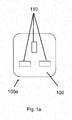
- Figure 1a shows a schematic front view of an electrical outlet 100a used according to UK standards.
- the electrical outlet 100a includes a cover plate 120 having slots 110 arranged therein to receive the pins of a corresponding electrical plug (not shown).
- the electrical outlet 100a shown in Figure 1a comprises three rectangular slots 110 arranged at three points of a triangle.
- Figure 1b shows an electrical outlet 100b used according to certain European standards.
- the cover plate 120 of the electrical outlet 100b shown in Figure 1b comprises a recessed portion 130 for receiving the body of a corresponding electrical plug.
- the slot arrangement of the electrical outlet 100b comprises two circular slots 110 arranged in a line for receiving the pins of a corresponding electrical plug.
- the slots 110 such as those shown in Figures 1a and 1b provide access to electrical contacts which are connected to the mains power supply.
- the pins of the plug make an electrical connection with the contacts.
- the plug is then able to supply power to an electronic device to which it is attached.
- the slot arrangements on electrical outlets may comprise circular, rectangular or otherwise shaped slots.
- the slots may be arranged perpendicular, parallel or at an angle to one other.
- the slots may be arranged in a straight vertical or horizontal line relative to the cover plate, in rows on the cover plate or otherwise.
- Cover plates 120 of a socket outlet may comprise a recessed portion 130 for receiving the body of a plug as shown in Figure 1b , or may be substantially flat, as shown in Figure 1a .
- the cover plate 120 of an electrical outlet may comprise plastic, metal or any other suitable material
- an electronic device including a plug made to the standards of one country cannot be used in another country without either replacing the plug (if the device supports the correct voltage and or frequency) or using an adapter.
- This diversification is not only an inconvenience but introduces costs and waste.
- FIG. 2 shows an electrical outlet 200 according to one example.
- the socket outlet includes a camera 210 and six slot arrangements 220a-f arranged on a first plate 230.
- Each slot arrangement 220a-f is designed for use according to a different standard, and thus has differently shaped slots arranged in differing patterns.
- six slot arrangements are shown in the example electrical outlet 200, an electrical outlet according to embodiments may comprise two or more slot arrangements.
- the slot arrangements may comprise slot arrangements according to any suitable standard.
- Same socket inputs for example ground socket inputs, can be connected to each other internally on the electrical outlet 200.
- the electrical outlet includes a cover arrangement that is configurable between a first configuration in which a first slot arrangement is exposed to receive the pins of an electrical plug and the second slot arrangement is not exposed to receive pins of an electrical plug, and at least one second configuration in which a second slot arrangement is exposed to receive the pins of an electrical plug and the first slot arrangement is not exposed to receive pins of an electrical plug.
- Figure 3 shows the electrical outlet 200 of Figure 2 and a movable cover 340.
- the cover 340 comprises an aperture 350 which, in a first position as shown, is arranged to expose one of the slot arrangements 220a of the electrical outlet such that the slot arrangement can receive a corresponding electrical plug.
- the cover 340 can be moved to a respective position for each of the slot arrangements 220a-f so that the aperture 350 is positioned over the respective slot arrangement.
- the respective slot arrangement is thus arranged to receive a corresponding electrical plug.
- the cover 340 prevents access to slot arrangements other than the exposed slot arrangement.
- a cover arrangement may comprise a plurality of covers, each cover being associated with a respective one of the slot arrangements and arranged to be expose or prevent access to the slot arrangement as determined.
- the cover arrangement may be arranged such that in one configuration, none of the slot arrangements 220a-f are exposed.
- the electrical outlet 200 described with reference to Figures 2 and 3 may include a controller (not shown).
- the controller is configured to determine which of the slot arrangements is to be exposed based on plug identity.
- the plug identity can be determined based on image data received from camera 210.
- the image data may be provided by the controller to a server via the internet for processing. Alternatively or additionally, identification of the plug identity may take place locally at the controller.
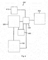
- FIG 4 shows an example of a control system 400.
- the control system includes the electrical outlet 200 as described with reference to Figures 2 and 3 and a controller 440.
- the controller 440 may be a microcontroller.
- the system 440 includes a sensor 410.
- the sensor 410 may comprise the camera 210.
- the sensor 410 is in communication with the controller 440.
- the sensor 410 is arranged to sense the presence of a plug and provide plug identity information to the controller 440.
- the controller 440 may be in communication with a remote server 450.
- the connection may be a wireless and/or wired connection.
- the controller 440 is configured to send the plug identity information to the remote server 450 and receive plug identity information from the remote server 450.
- the identification of the plug identity may take place at the controller 440 or at the remote server 450. This may be carried out by for example comparing an image of the plug that is captured by the camera 210 with images of a range of plugs according to different standards which are stored at the remote server 450.
- Machine learning may be used as part of the process to identify the plug type.
- Machine learning is a sub-domain in computer science which enables computers to learn without being explicitly programmed. This is achieved by training and using relevant machine learning models.
- the training requires a machine learning algorithm with relevant training data to learn from.
- the machine learning algorithm finds patterns in the training data and assigns the attributes of the input data to the target.
- the training data needs the correct answer which is known as target.
- the machine learning model attributes to the resulting output of the training.
- the generation of the machine learning model enables predictions of new data of which the target is not known. Therefore, identifying the matching plug and plug type requires training the model with many different plugs and plug types. The ability to identifying plug types is increased due to machine learning.
- the controller 440 is configured to determine which of the plurality of slot arrangements 220a-f to expose based on the electrical plug identity.
- the system 400 includes an actuator 430.
- the actuator may comprise a motor, such as a servomotor.
- the actuator 430 is configured to receive control messages from the controller 440 and cause reconfiguration of the cover arrangement.
- the system 400 includes a voltage converter 460.
- the voltage converter 460 is configured to receive control messages from the controller 440.
- the voltage converter 460 is configured to convert AC mains voltage to the voltage and frequency suitable for a given plug type.
- the controller 440 is configured to determine if voltage conversion is required and, if so, provide a control message to the voltage converter including an indication of the voltage required.
- the controller 440 is configured to determine which voltage is required based on the electrical plug identity.
- the identified plug type is used to identify the voltage that is needed since different plug types are associated with different voltages throughout the world.
- the camera 210 senses the plug.
- the camera 210 takes a photo of the plug and provides the image data to the controller 440.
- the data is transmitted to the server 450.
- the server 450 identifies the plug identity based on the data and sends an indication of the plug identity to the controller 440.
- the controller 440 determines which of the plurality of slot arrangements 220a-f to expose based on the electrical plug identity and provides a control message to the actuator 430.
- the actuator 430 causes the cover 340 to move such that the aperture 350 is aligned with the determined slot arrangement and access to the other slot arrangements is disabled.
- the controller 440 determines whether voltage conversion is required and, if so, provides a control message to the voltage converter 460.
- the voltage converter 460 changes the voltage type in response to the control message received from the controller, for example, from 220 volts to 110 volts.
- the electrical outlet is now ready for use.
- processor or processing system or circuitry referred to herein may in practice be provided by a single chip or integrated circuit or plural chips or integrated circuits, optionally provided as a chipset, an application-specific integrated circuit (ASIC), field-programmable gate array (FPGA), digital signal processor (DSP), graphics processing units (GPUs), etc.
- the chip or chips may comprise circuitry (as well as possibly firmware) for embodying at least one or more of a data processor or processors, a digital signal processor or processors, baseband circuitry and radio frequency circuitry, which are configurable so as to operate in accordance with the exemplary embodiments.
- the exemplary embodiments may be implemented at least in part by computer software stored in (non-transitory) memory and executable by the processor, or by hardware, or by a combination of tangibly stored software and hardware (and tangibly stored firmware).
- the invention also extends to computer programs, particularly computer programs on or in a carrier, adapted for putting the invention into practice.
- the program may be in the form of non-transitory source code, object code, a code intermediate source and object code such as in partially compiled form, or in any other non-transitory form suitable for use in the implementation of processes according to the invention.
- the carrier may be any entity or device capable of carrying the program.
- the carrier may comprise a storage medium, such as a solid-state drive (SSD) or other semiconductor-based RAM; a ROM, for example a CD ROM or a semiconductor ROM; a magnetic recording medium, for example a floppy disk or hard disk; optical memory devices in general; etc.
- SSD solid-state drive
- ROM read-only memory
- magnetic recording medium for example a floppy disk or hard disk
- optical memory devices in general etc.
Landscapes
- Connector Housings Or Holding Contact Members (AREA)
- Details Of Connecting Devices For Male And Female Coupling (AREA)
Abstract
There is provided an electrical outlet apparatus (200) comprising a first slot arrangement (220a) for receiving pins of a first electrical plug and at least one second slot arrangement (220b) for receiving pins of a second electrical plug. The electrical outlet apparatus (200) comprises a cover arrangement. The cover arrangement is configurable between a first configuration in which the first slot arrangement (220a) is exposed to receive the pins of an electrical plug and the second slot arrangement (220b) is not exposed to receive pins of an electrical plug and at least one second configuration in which the second slot arrangement (220b) is exposed to receive the pins of an electrical plug and the first slot arrangement (220a) is not exposed to receive pins of an electrical plug.
Description
- The present disclosure relates to an electrical outlet apparatus for receiving an electrical plug and a method of operating an electrical outlet apparatus.
- Electrical outlets allow electrical equipment to be connected, via a power plug, to a primary, or mains, power supply. The voltage and frequency of the mains power supply differs across countries and regions. In addition, safety requirements for plug design, to avoid electric shocks and fires, vary from country to country. Consequently, electrical plugs and socket outlets differ in voltage and current rating as well as the shape, size and type of connectors. Approximately 20 types of sockets and connectors are in common use around the world.
- According to a first aspect disclosed herein, there is provided an electrical outlet apparatus comprising a first slot arrangement for receiving pins of a first electrical plug, at least one second slot arrangement for receiving pins of a second electrical plug and a cover arrangement that is configurable between a first configuration in which the first slot arrangement is exposed to receive the pins of an electrical plug and the second slot arrangement is not exposed to receive pins of an electrical plug, and at least one second configuration in which the second slot arrangement is exposed to receive the pins of an electrical plug and the first slot arrangement is not exposed to receive pins of an electrical plug.
- The electrical outlet apparatus may comprise a controller in communication with an actuator, the controller being configured to send control signals to the actuator to cause the cover arrangement to change between the first configuration and the at least one second configuration.
- The actuator may be a servomotor.
- The electrical outlet apparatus may comprise a sensor, wherein the controller is in communication with the sensor, the sensor being arranged to sense an electrical plug and provide electrical plug identity information to the controller.
- The controller may be configured to determine which of the first slot arrangement and the at least one second slot arrangement to expose based on the electrical plug identity information.
- The sensor may comprise a camera.
- The controller may be configured to determine which of the first slot arrangement and the at least one second slot arrangement to expose based on data received from a remote server.
- The electrical outlet apparatus may comprise a voltage converter, wherein the controller is in communication with the voltage converter and configured to send control signals to the voltage converter to cause the voltage converter to change voltage type.
- The cover arrangement may be configurable to a third configuration in which no arrangement of slots is exposed.
- The cover arrangement may comprise a movable cover. The movable cover may comprises an aperture. The cover arrangement may comprise a plurality of covers, each cover associated with a respective one of the slot arrangements.
- According to a second aspect disclosed herein there is provided a method of operating an electrical outlet apparatus comprising determining which of a first slot arrangement for receiving pins of a first electrical plug and at least one second slot arrangement for receiving pins of a second electrical plug to expose to receive pins of an electrical plug and configuring a cover arrangement to a configuration in which the determined slot arrangement is exposed to receive pins of the corresponding electrical plug.
- The method may comprise sending control signals from a controller to an actuator to configure the cover arrangement to the configuration in which the determined slot arrangement is exposed to receive pins of the corresponding electrical plug.
- The method may comprise sensing an electrical plug at a sensor and providing plug identity information from the sensor to the controller for use in determining which the first slot arrangement and the second slot arrangement to expose.
- The method may comprise providing the plug identity information to a remote sensor and, in response, receiving an indication of the plug identity from the remote sensor.
- The method may comprise determining the voltage required for an electrical plug and providing control signals to a voltage converter to cause the voltage converter to convert mains voltage to the determined voltage.
- To assist understanding of the present disclosure and to show how embodiments may be put into effect, reference is made by way of example to the accompanying drawings in which:
-
Figure 1a shows a schematic front view of an example electrical outlet; -
Figure 1b shows a schematic front view of an alternative example electrical outlet; -
Figure 2 shows a schematic front view of an uncovered electrical outlet apparatus according to an example; -
Figure 3 shows a schematic front view of an electrical outlet apparatus with a cover according to one example; -
Figure 4 shows a schematic view of an electrical outlet control system according to an example. -
Figure 1a shows a schematic front view of anelectrical outlet 100a used according to UK standards. Theelectrical outlet 100a includes acover plate 120 havingslots 110 arranged therein to receive the pins of a corresponding electrical plug (not shown). Theelectrical outlet 100a shown inFigure 1a comprises threerectangular slots 110 arranged at three points of a triangle. -
Figure 1b shows anelectrical outlet 100b used according to certain European standards. Thecover plate 120 of theelectrical outlet 100b shown inFigure 1b comprises arecessed portion 130 for receiving the body of a corresponding electrical plug. The slot arrangement of theelectrical outlet 100b comprises twocircular slots 110 arranged in a line for receiving the pins of a corresponding electrical plug. - The
slots 110 such as those shown inFigures 1a and1b provide access to electrical contacts which are connected to the mains power supply. When a corresponding electrical plug is inserted into the electrical outlet, the pins of the plug make an electrical connection with the contacts. The plug is then able to supply power to an electronic device to which it is attached. - Although two electrical outlet designs are shown in
Figure 1a and Figure Ib, many other electrical outlets are in common use. The slot arrangements on electrical outlets may comprise circular, rectangular or otherwise shaped slots. The slots may be arranged perpendicular, parallel or at an angle to one other. The slots may be arranged in a straight vertical or horizontal line relative to the cover plate, in rows on the cover plate or otherwise.Cover plates 120 of a socket outlet may comprise arecessed portion 130 for receiving the body of a plug as shown inFigure 1b , or may be substantially flat, as shown inFigure 1a . Thecover plate 120 of an electrical outlet may comprise plastic, metal or any other suitable material - In addition to the different arrangements of slots provided in different electrical outlets, different electrical outlets operate using different voltages and frequencies, depending on the AC mains voltage and frequency in the country the outlet is designed to be used in. As a result, even if a plug can be made to fit an electrical outlet, the frequency and/or voltage of the power supplied by the electrical outlet may not be suitable for the device to which the electrical plug is attached.
- In effect, an electronic device including a plug made to the standards of one country cannot be used in another country without either replacing the plug (if the device supports the correct voltage and or frequency) or using an adapter. This diversification is not only an inconvenience but introduces costs and waste.
-
Figure 2 shows anelectrical outlet 200 according to one example. The socket outlet includes acamera 210 and sixslot arrangements 220a-f arranged on afirst plate 230. Eachslot arrangement 220a-f is designed for use according to a different standard, and thus has differently shaped slots arranged in differing patterns. Although six slot arrangements are shown in the exampleelectrical outlet 200, an electrical outlet according to embodiments may comprise two or more slot arrangements. The slot arrangements may comprise slot arrangements according to any suitable standard. - Same socket inputs, for example ground socket inputs, can be connected to each other internally on the
electrical outlet 200. - The electrical outlet includes a cover arrangement that is configurable between a first configuration in which a first slot arrangement is exposed to receive the pins of an electrical plug and the second slot arrangement is not exposed to receive pins of an electrical plug, and at least one second configuration in which a second slot arrangement is exposed to receive the pins of an electrical plug and the first slot arrangement is not exposed to receive pins of an electrical plug.
-
Figure 3 shows theelectrical outlet 200 ofFigure 2 and amovable cover 340. Thecover 340 comprises anaperture 350 which, in a first position as shown, is arranged to expose one of theslot arrangements 220a of the electrical outlet such that the slot arrangement can receive a corresponding electrical plug. Thecover 340 can be moved to a respective position for each of theslot arrangements 220a-f so that theaperture 350 is positioned over the respective slot arrangement. The respective slot arrangement is thus arranged to receive a corresponding electrical plug. Thecover 340 prevents access to slot arrangements other than the exposed slot arrangement. - Alternatively to the
cover 340 described with reference toFigure 3 , a cover arrangement may comprise a plurality of covers, each cover being associated with a respective one of the slot arrangements and arranged to be expose or prevent access to the slot arrangement as determined. - The cover arrangement may be arranged such that in one configuration, none of the
slot arrangements 220a-f are exposed. - The
electrical outlet 200 described with reference toFigures 2 and3 may include a controller (not shown). The controller is configured to determine which of the slot arrangements is to be exposed based on plug identity. The plug identity can be determined based on image data received fromcamera 210. In one example, the image data may be provided by the controller to a server via the internet for processing. Alternatively or additionally, identification of the plug identity may take place locally at the controller. -
Figure 4 shows an example of acontrol system 400. The control system includes theelectrical outlet 200 as described with reference toFigures 2 and3 and acontroller 440. Thecontroller 440 may be a microcontroller. - The
system 440 includes asensor 410. Thesensor 410 may comprise thecamera 210. Thesensor 410 is in communication with thecontroller 440. Thesensor 410 is arranged to sense the presence of a plug and provide plug identity information to thecontroller 440. - The
controller 440 may be in communication with aremote server 450. The connection may be a wireless and/or wired connection. In one example, thecontroller 440 is configured to send the plug identity information to theremote server 450 and receive plug identity information from theremote server 450. The identification of the plug identity may take place at thecontroller 440 or at theremote server 450. This may be carried out by for example comparing an image of the plug that is captured by thecamera 210 with images of a range of plugs according to different standards which are stored at theremote server 450. - Machine learning may be used as part of the process to identify the plug type. Machine learning is a sub-domain in computer science which enables computers to learn without being explicitly programmed. This is achieved by training and using relevant machine learning models. The training requires a machine learning algorithm with relevant training data to learn from. The machine learning algorithm finds patterns in the training data and assigns the attributes of the input data to the target. The training data needs the correct answer which is known as target. The machine learning model attributes to the resulting output of the training. The generation of the machine learning model enables predictions of new data of which the target is not known. Therefore, identifying the matching plug and plug type requires training the model with many different plugs and plug types. The ability to identifying plug types is increased due to machine learning.
- The
controller 440 is configured to determine which of the plurality ofslot arrangements 220a-f to expose based on the electrical plug identity. - The
system 400 includes anactuator 430. The actuator may comprise a motor, such as a servomotor. Theactuator 430 is configured to receive control messages from thecontroller 440 and cause reconfiguration of the cover arrangement. - The
system 400 includes avoltage converter 460. Thevoltage converter 460 is configured to receive control messages from thecontroller 440. Thevoltage converter 460 is configured to convert AC mains voltage to the voltage and frequency suitable for a given plug type. Thecontroller 440 is configured to determine if voltage conversion is required and, if so, provide a control message to the voltage converter including an indication of the voltage required. Thecontroller 440 is configured to determine which voltage is required based on the electrical plug identity. The identified plug type is used to identify the voltage that is needed since different plug types are associated with different voltages throughout the world. - In use, the
camera 210 senses the plug. Thecamera 210 takes a photo of the plug and provides the image data to thecontroller 440. The data is transmitted to theserver 450. Theserver 450 identifies the plug identity based on the data and sends an indication of the plug identity to thecontroller 440. - The
controller 440 determines which of the plurality ofslot arrangements 220a-f to expose based on the electrical plug identity and provides a control message to theactuator 430. In response to the control message, theactuator 430 causes thecover 340 to move such that theaperture 350 is aligned with the determined slot arrangement and access to the other slot arrangements is disabled. - The
controller 440 determines whether voltage conversion is required and, if so, provides a control message to thevoltage converter 460. - The
voltage converter 460 changes the voltage type in response to the control message received from the controller, for example, from 220 volts to 110 volts. - The electrical outlet is now ready for use.
- With the use of an electrical outlet as described above, both voltage and plug type adapters are no longer required.
- It will be understood that the processor or processing system or circuitry referred to herein may in practice be provided by a single chip or integrated circuit or plural chips or integrated circuits, optionally provided as a chipset, an application-specific integrated circuit (ASIC), field-programmable gate array (FPGA), digital signal processor (DSP), graphics processing units (GPUs), etc. The chip or chips may comprise circuitry (as well as possibly firmware) for embodying at least one or more of a data processor or processors, a digital signal processor or processors, baseband circuitry and radio frequency circuitry, which are configurable so as to operate in accordance with the exemplary embodiments. In this regard, the exemplary embodiments may be implemented at least in part by computer software stored in (non-transitory) memory and executable by the processor, or by hardware, or by a combination of tangibly stored software and hardware (and tangibly stored firmware).
- Although at least some aspects of the embodiments described herein with reference to the drawings comprise computer processes performed in processing systems or processors, the invention also extends to computer programs, particularly computer programs on or in a carrier, adapted for putting the invention into practice. The program may be in the form of non-transitory source code, object code, a code intermediate source and object code such as in partially compiled form, or in any other non-transitory form suitable for use in the implementation of processes according to the invention. The carrier may be any entity or device capable of carrying the program. For example, the carrier may comprise a storage medium, such as a solid-state drive (SSD) or other semiconductor-based RAM; a ROM, for example a CD ROM or a semiconductor ROM; a magnetic recording medium, for example a floppy disk or hard disk; optical memory devices in general; etc.
- The examples described herein are to be understood as illustrative examples of embodiments of the invention. Further embodiments and examples are envisaged. Any feature described in relation to any one example or embodiment may be used alone or in combination with other features. In addition, any feature described in relation to any one example or embodiment may also be used in combination with one or more features of any other of the examples or embodiments, or any combination of any other of the examples or embodiments. Furthermore, equivalents and modifications not described herein may also be employed within the scope of the invention, which is defined in the claims.
Claims (15)
- An electrical outlet apparatus comprising:a first slot arrangement for receiving pins of a first electrical plug;at least one second slot arrangement for receiving pins of a second electrical plug; anda cover arrangement that is configurable between a first configuration in which the first slot arrangement is exposed to receive the pins of an electrical plug and the second slot arrangement is not exposed to receive pins of an electrical plug, and at least one second configuration in which the second slot arrangement is exposed to receive the pins of an electrical plug and the first slot arrangement is not exposed to receive pins of an electrical plug.
- An electrical outlet apparatus according to claim 1, comprising a controller in communication with an actuator, the controller being configured to send control signals to the actuator to cause the cover arrangement to change between the first configuration and the at least one second configuration.
- An electrical outlet apparatus according to claim 2, wherein the actuator is a servomotor.
- An electrical outlet apparatus according to claim 2 or claim 3, comprising a sensor, wherein the controller is in communication with the sensor, the sensor being arranged to sense an electrical plug and provide electrical plug identity information to the controller.
- An electrical outlet apparatus according to claim 4, wherein the controller is configured to determine which of the first slot arrangement and the at least one second slot arrangement to expose based on the electrical plug identity information.
- An electrical outlet apparatus according to claim 4 or claim 5, wherein the sensor comprises a camera.
- An electrical outlet apparatus according to any of claims 2 to 6, wherein the controller is configured to determine which of the first slot arrangement and the at least one second slot arrangement to expose based on data received from a remote server.
- An electrical outlet apparatus according to any of claims 2 to 7, comprising a voltage converter, wherein the controller is in communication with the voltage converter and configured to send control signals to the voltage converter to cause the voltage converter to change voltage type.
- An electrical outlet apparatus according to any one of claims 1 to 8, wherein the cover arrangement is configurable to a third configuration in which no arrangement of slots is exposed.
- An electrical outlet apparatus according to any of claims 1 to 9, wherein the cover arrangement comprises a movable cover.
- A method of operating an electrical outlet apparatus comprising:determining which of a first slot arrangement for receiving pins of a first electrical plug and at least one second slot arrangement for receiving pins of a second electrical plug to expose to receive pins of an electrical plug; andconfiguring a cover arrangement to a configuration in which the determined slot arrangement is exposed to receive pins of the corresponding electrical plug.
- A method according to claim 11, comprising sending control signals from a controller to an actuator to configure the cover arrangement to the configuration in which the determined slot arrangement is exposed to receive pins of the corresponding electrical plug.
- A method according to claim 12, comprising sensing an electrical plug at a sensor and providing plug identity information from the sensor to the controller for use in determining which the first slot arrangement and the second slot arrangement to expose.
- A method according to claim 13, comprising providing the plug identity information from the controller to a remote sensor and, in response, receiving an indication of the plug identity from the remote sensor.
- A method according to any one of claims 9 to 14 comprising:determining the voltage required for an electrical plug; andproviding control signals to a voltage converter to cause the voltage converter to convert mains voltage to the determined voltage.
Priority Applications (2)
| Application Number | Priority Date | Filing Date | Title |
|---|---|---|---|
| EP17204513.0A EP3493332A1 (en) | 2017-11-29 | 2017-11-29 | Electrical outlet apparatus and method of operation |
| TR2017/21531A TR201721531A2 (en) | 2017-11-29 | 2017-12-25 | Electrical Outlet Apparatus And Working Method |
Applications Claiming Priority (1)
| Application Number | Priority Date | Filing Date | Title |
|---|---|---|---|
| EP17204513.0A EP3493332A1 (en) | 2017-11-29 | 2017-11-29 | Electrical outlet apparatus and method of operation |
Publications (1)
| Publication Number | Publication Date |
|---|---|
| EP3493332A1 true EP3493332A1 (en) | 2019-06-05 |
Family
ID=60515250
Family Applications (1)
| Application Number | Title | Priority Date | Filing Date |
|---|---|---|---|
| EP17204513.0A Withdrawn EP3493332A1 (en) | 2017-11-29 | 2017-11-29 | Electrical outlet apparatus and method of operation |
Country Status (2)
| Country | Link |
|---|---|
| EP (1) | EP3493332A1 (en) |
| TR (1) | TR201721531A2 (en) |
Citations (3)
| Publication number | Priority date | Publication date | Assignee | Title |
|---|---|---|---|---|
| DE102008063110A1 (en) * | 2008-12-24 | 2010-07-01 | Merten Gmbh & Co. Kg | Locking system for a socket |
| US8399765B1 (en) * | 2006-11-03 | 2013-03-19 | Hubbell Incorporated | Safety outlet cover |
| EP2911249A1 (en) * | 2014-02-20 | 2015-08-26 | 4 Box S.r.l. | Multiple electrical socket |
-
2017
- 2017-11-29 EP EP17204513.0A patent/EP3493332A1/en not_active Withdrawn
- 2017-12-25 TR TR2017/21531A patent/TR201721531A2/en unknown
Patent Citations (3)
| Publication number | Priority date | Publication date | Assignee | Title |
|---|---|---|---|---|
| US8399765B1 (en) * | 2006-11-03 | 2013-03-19 | Hubbell Incorporated | Safety outlet cover |
| DE102008063110A1 (en) * | 2008-12-24 | 2010-07-01 | Merten Gmbh & Co. Kg | Locking system for a socket |
| EP2911249A1 (en) * | 2014-02-20 | 2015-08-26 | 4 Box S.r.l. | Multiple electrical socket |
Also Published As
| Publication number | Publication date |
|---|---|
| TR201721531A2 (en) | 2019-06-21 |
Similar Documents
| Publication | Publication Date | Title |
|---|---|---|
| US8928189B2 (en) | Power connector between serial interfaces | |
| TWI573368B (en) | Portable electronic device and charging method thereof | |
| EP3413428B1 (en) | Charging device, terminal device and charging system | |
| JP2017507638A (en) | Method for processing impedance abnormality of power adapter, terminal and charging circuit | |
| CA3025545C (en) | Method and apparatus for monitoring status of relay | |
| US10074949B1 (en) | Electronic device and a method for detecting the connecting direction of two electronic components | |
| US10694269B2 (en) | Optical cable identification tool | |
| US10267340B2 (en) | Concentrically symmetric connector in blind mate round fan assembly | |
| TW201429071A (en) | Polarity control for a flat connector | |
| US20180069338A1 (en) | Connector, socket, method for providing signals to connector by socket, electronic equipment | |
| EP4054036A1 (en) | Circuit breaker identification method and apparatus, and device | |
| EP3493332A1 (en) | Electrical outlet apparatus and method of operation | |
| CN113874810B (en) | Power supply unit with connector protection circuit | |
| US20190237914A1 (en) | Electrical Socket Apparatus, Electrical Plug Apparatus and Method of Operation | |
| TWI509418B (en) | A data transfer system and method of controlling the same | |
| US20190227973A1 (en) | Switch for reversible interface | |
| US20090167099A1 (en) | Switch Device for Switching Different Type Signals | |
| CN111858423A (en) | Electronic equipment protection device and electronic equipment protection method | |
| CN103927281A (en) | Transmission interface detection system and transmission interface detection method | |
| CN114624524A (en) | Charging detection method, device and equipment | |
| US20170300343A1 (en) | Connection Device for a Modular Computing System | |
| CN114759631A (en) | Power module, insert frame and electrical power generating system | |
| US20250208233A1 (en) | Quality detection for magnetically coupled interfaces | |
| CN110266076B (en) | Charging control system for walking robot | |
| US9398435B2 (en) | Indicating physical change in relation to an exterior of a network node module |
Legal Events
| Date | Code | Title | Description |
|---|---|---|---|
| PUAI | Public reference made under article 153(3) epc to a published international application that has entered the european phase |
Free format text: ORIGINAL CODE: 0009012 |
|
| STAA | Information on the status of an ep patent application or granted ep patent |
Free format text: STATUS: THE APPLICATION HAS BEEN PUBLISHED |
|
| AK | Designated contracting states |
Kind code of ref document: A1 Designated state(s): AL AT BE BG CH CY CZ DE DK EE ES FI FR GB GR HR HU IE IS IT LI LT LU LV MC MK MT NL NO PL PT RO RS SE SI SK SM TR |
|
| AX | Request for extension of the european patent |
Extension state: BA ME |
|
| STAA | Information on the status of an ep patent application or granted ep patent |
Free format text: STATUS: THE APPLICATION IS DEEMED TO BE WITHDRAWN |
|
| 18D | Application deemed to be withdrawn |
Effective date: 20191206 |