EP3493170A2 - Wireless tamper device - Google Patents
Wireless tamper device Download PDFInfo
- Publication number
- EP3493170A2 EP3493170A2 EP18204984.1A EP18204984A EP3493170A2 EP 3493170 A2 EP3493170 A2 EP 3493170A2 EP 18204984 A EP18204984 A EP 18204984A EP 3493170 A2 EP3493170 A2 EP 3493170A2
- Authority
- EP
- European Patent Office
- Prior art keywords
- wtd
- tamper
- layer probe
- tamper state
- physical trigger
- Prior art date
- Legal status (The legal status is an assumption and is not a legal conclusion. Google has not performed a legal analysis and makes no representation as to the accuracy of the status listed.)
- Granted
Links
Images




Classifications
-
- G—PHYSICS
- G08—SIGNALLING
- G08B—SIGNALLING SYSTEMS, e.g. PERSONAL CALLING SYSTEMS; ORDER TELEGRAPHS; ALARM SYSTEMS
- G08B13/00—Burglar, theft or intruder alarms
- G08B13/02—Mechanical actuation
- G08B13/08—Mechanical actuation by opening, e.g. of door, of window, of drawer, of shutter, of curtain, of blind
-
- G—PHYSICS
- G09—EDUCATION; CRYPTOGRAPHY; DISPLAY; ADVERTISING; SEALS
- G09F—DISPLAYING; ADVERTISING; SIGNS; LABELS OR NAME-PLATES; SEALS
- G09F3/00—Labels, tag tickets, or similar identification or indication means; Seals; Postage or like stamps
- G09F3/02—Forms or constructions
- G09F3/03—Forms or constructions of security seals
- G09F3/0305—Forms or constructions of security seals characterised by the type of seal used
- G09F3/0329—Forms or constructions of security seals characterised by the type of seal used having electronic sealing means
-
- G—PHYSICS
- G09—EDUCATION; CRYPTOGRAPHY; DISPLAY; ADVERTISING; SEALS
- G09F—DISPLAYING; ADVERTISING; SIGNS; LABELS OR NAME-PLATES; SEALS
- G09F3/00—Labels, tag tickets, or similar identification or indication means; Seals; Postage or like stamps
- G09F3/02—Forms or constructions
- G09F3/03—Forms or constructions of security seals
- G09F3/0305—Forms or constructions of security seals characterised by the type of seal used
- G09F3/0341—Forms or constructions of security seals characterised by the type of seal used having label sealing means
Definitions
- the present disclosure is related to sensors, and in particular, to sensors that detect tampering.
- the bins above passengers, washrooms, and galleys in a commercial airliner train or bus may need to be easily accessible at one point or another while traveling.
- the washrooms in a vehicle may need to be inspected, secured, and closed prior to passengers boarding the vehicle for security purposes.
- crew related items may need to be stored in an overhead bin or closet that also needs to be closed and secured.
- storage compartments in a galley may also need to be inspected, closed, and secured.
- the approach to securing these areas is generally limited to inspecting, closing, and placing a device at the access of the area that may be a door or flap.
- the device may include multiple devices or items that provide visual evidence of tamper, such as, for example, a zip tie, an adhesive seal or tape, and a plastic padlock that are permanently altered or broken by a tamper event.
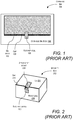
- FIG. 1 a system block diagram of an example of an implementation of a known security seal 100 is shown attached to an overhead bin door 102 of an overhead bin 104.
- the overhead bin 104 may be located within an aircraft, bus, train, or other passenger vehicle.
- the security seal 100 is located on both the overhead bin body 106 and the overhead bin door 102 in a straddling fashion that bridges the gap 108 between the overhead bin body 106 and the overhead bin door 102.
- FIG. 2 a system block diagram of an example of another implementation of a known security device 200 is shown attached to a secure box 202.
- the secure box 202 may be located within an aircraft, bus, train, or other passenger vehicle.
- the security device 200 may be a padlock type device, zip tie, adhesive seal or tap, or other similar device.
- the security box 202 may be a storage location having a lid 204 that is utilized to store secure items that include, for example, crew items and/or emergency equipment, life vest(s), fire extinguisher, automated external defibrillator ("AED”), etc.
- AED automated external defibrillator
- the security device 200 may be a padlock type device that attaches to an attachment device 206 that is located on both the lid 204 and a front wall 208 of the security box 202 in a straddling fashion that bridges a gap 210 between the front wall 208 and the lid 204.
- the security seals are a type of tape or device that are usually known as, for example, tamper seals, security seals, tamper evident security seals, security tapes, tamper evident tapes, plastic zip ties, or padlocks, which for the purpose of simplicity are herein referred to as "security seals" or "security devices.”
- these security seals or devices are designed to be visually inspected and easily recognized if tampered with or broken.
- security seals or devices are utilized in commercial aircraft to help ensure that any items placed onto the aircraft have been cleared by the relevant security personnel, and once cleared, those items are sealed to make sure that they cannot be tampered with before, during and post flight.
- a wireless tamper device (“WTD”) is disclosed.
- the WTD includes a transmitter, multi-layer probe, processing device, and power supply.
- the processing device is in signal communication with the multi-layer probe and the power supply is in signal communication with the transmitter and processing device.
- the processing device includes a processor and a computer-readable medium (“CRM").
- the CRM has encoded thereon computer-executable instructions to cause the processor to initiating a tamper state to untampered, detect a physical trigger on the multi-layer probe, and set the tamper state to tampered in response to detecting the physical trigger.
- the WTD performs a method that includes initiating a tamper state to untampered, detecting a physical trigger, and setting the tamper state to tampered in response to detecting the physical trigger.
- the WTD includes a transmitter, multi-layer probe having predetermined electrical characteristics, processing device, and power supply.
- the processing device is in signal communication with the multi-layer probe and the power supply is in signal communication with the transmitter and processing device.
- the processing device includes a processor and a computer-readable medium (“CRM").
- the CRM has encoded thereon computer-executable instructions to cause the processor to initiate a tamper state to untampered, detect a physical trigger on the multi-layer probe, and set the tamper state to tampered in response to detecting the physical trigger.
- the WTD performs a method that includes initiating a tamper state to untampered, detecting a physical trigger, and setting the tamper state to tampered in response to detecting the physical trigger.
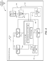
- the WTD 300 includes a transmitter 302, multi-layer probe 304, processing device 306, and a power supply 308.
- the WTD 300 may also include an antenna 310, receiver 312, optional sensor 314, and optional accelerometer 315 (or other solid-state electronic sensor capable of measuring movement and/or vibration).
- the processing device 306 is in signal communication with the transmitter 302, receiver 312, power supply 308, optional sensor 314, and the optional accelerometer 315 via signal paths 316, 318, 320, 322, and 323, respectively.
- the power supply 308 is in signal communication with the transmitter 302, receiver 312, and the optional sensor 314 via signal paths 324, 326, and 328, respectively.
- the antenna 310 is in signal communication with the transmitter 302 and receiver 312 via signal paths 330 and 332, respectively.
- the multi-layer probe 304 is in signal communication with the optional sensor 314 via signal path 334 and the processing device 306 via the optional sensor 314 and signal paths 334 and 322.
- the WTD 300 may optionally also include an optional trigger switch 336 in signal communication with the processing device 306 via signal path 338.
- the optional accelerometer 315 may be in signal communication with the multi-layer probe 304 via signal path 339.
- the processing device 306 may include a processor 340 and a computer-readable medium (“CRM”) 342.
- the CRM 342 has encoded thereon computer-executable instructions to cause the processor 340 to perform different functions in the operation of the WTD 300.
- the processor 340 may be any microprocessor or similar device, such as, for example, a central processing unit (“CPU"), digital signal processing (“DSP”) device, application specific integrated circuit (“ASIC”), or a field programmable-gate array (“FPGA”).
- the CRM 342 may be software or firmware and the computer-executable instructions stored on the CRM 342 may include, for example, an operating system, software, and other modules, programs, or applications that are loadable and executable by processor 340.
- the computer-executable instructions may include hardware logic (i.e., machine instructions) that controls the operation of the processor 340.
- the CRM 342 may be in signal communication with the processor 340 via a signal path that includes a bus.
- the power supply 308 may be a battery configured to power the WTD 300 for an extended period of time. It is appreciated by those of ordinary skill in the art that the transmitter 302 and receiver 312 may be independent devices or combined together to form part of a transceiver.
- the multi-layer probe 304 may be any type of multi-layer device capable of detecting a physical force (i.e., a physical trigger) associated with a tampering activity where the physical trigger may include physically damaging or breaking the multi-layer probe 304. Examples of the multi-layer probe 304 include multiple layers of material that may include a wire, electrical substrate, or other electrically conductive material.
- the multi-layer probe 304 may include two or more layers of material placed together that cause the multi-layer probe 304 to have predetermined electrical characteristics that may include, for example, a predetermined impedance, capacitance, inductance, dielectric properties, breakdown voltage, etc.
- predetermined electrical characteristics may include, for example, a predetermined impedance, capacitance, inductance, dielectric properties, breakdown voltage, etc.
- the multi-layer probe 304 may be physically modified or damaged such that the layers of material within the multi-layer probe 304 partially or fully move or separate from each other in a way that substantially alters and changes the electrical characteristics of the multi-layer probe 304 from the original predetermined electrical characteristics.
- the multi-layer probe 304 is an electrical implementation of a security device similar to, for example, a security tape (also known as security label) that is a type of adhesive tape used to detect tampering.
- security tape is a pressure sensitive tape or label with special tamper resistant or tamper evident features. These special tamper resistant or tamper evident features may include intentionally weak or frangible components that easily fracture or tear, printing which, when cut or torn, cannot easily be realigned, layers that easily delaminate to show entry or tampering, hidden print layers which indicated an opening or tampering, etc.
- the multi-layer probe 304 may also include special tamper resistant or tamper evident features that allow the WTD 300 to indicate that the WTD 300 has been tampered with.
- the multi-layer probe 304 may include multiple layers of material that are sandwiched together to form the multi-layer probe 304. As an example, some of these layers may be electrically conductive and some may be isolative that act as a dielectrics between the electrically conductive layers. In an example of operation, a current may be induced to flow between the electrically conductive layers and through the dielectric layers between the electrically conductive layers.
- the multi-layer probe 304 may have predetermined electrical characteristics that lets the multi-layer probe 304 allow a certain amount of current to flow through the multi-layer probe 304 with a corresponding predetermined voltage drop across the inputs to the multi-layer probe 304. Moreover, in this example, the multi-layer probe 304 may have a predetermined impedance value corresponding to combination of resistive, capacitive, and inductive properties of the multi-layer probe 304.
- this tamper will cause a physical variation or deformation of the layers within the multi-layer probe 304 that may change the distance, orientation, or both, between the electrically conductive layers and deformation or damage to the dielectric layers.
- this tamper may introduce cracks, breaks, and air gaps within layered structure of the multi-layer probe 304.
- the WTD 300 may utilize these changed electrical characteristics to identify a triggering event corresponding to a tampering event as experienced by the multi-layer probe 304.
- the multi-layer probe 304 may include multiple layers within the multi-layer probe 304 where one or more layers may include one or more electrical probes such as conductive strips or wires.
- the one or more electrical probes may include just one electrical wire or strip within the multi-layer probe 304 that is electrically connected to other devices of the WTD 300 and completes a circuit that passes a predetermined amount of current and has predetermined electrical characteristics.
- two or more electrical wires or strips may be utilized where the two or more electrical wires or strips interact with each other, e.g., one electrical wire or strip may act as an input to the multi-layer probe 304 while another electrical wire or strip may act as an output to the multi-layer probe 304.
- the first electrical wire or strip may be in signal communication with the second electrical wire or strip through the other dielectric layers of the multi-layer probe 304.
- this tamper will cause a physical variation or deformation of the layers within the multi-layer probe 304 that may change the distance, orientation, or both, between the electrically wires or strips and deformation or damage to the dielectric layers.
- the tamper may also damage or break one or more of the electrical wires or strips. As described earlier, this tamper may introduce cracks, breaks, and air gaps within layered structure of the multi-layer probe 304.
- the WTD 300 may utilize these changed electrical characteristics to identify a triggering event corresponding to a tampering event as experienced by the multi-layer probe 304.
- the antenna 310 may be the multi-layer probe 304.
- the antenna 310 and multi-layer probe 304 may be the same element (i.e., device, component, module, or circuit) where the antenna 310 may have an antenna length that is approximately equal to a fractional length (such as, for example, a half-wavelength) of an operating frequency of operation of the transmitter 302 and receiver 312.
- the physical trigger may be a damaging or breaking of the antenna 310 that results in the reduction of the antenna length.
- changing the antenna length of the antenna 310 will alter the electrical properties of the antenna 310 that include, for example, causing the antenna 310 to operate at a new shifted frequency (i.e., it will result in a new operating frequency that is equal to the new reduced antenna length of the antenna 310 after the breakage or damage of the antenna 310 by the tampering activity), be less efficient at receiving and transmitting signals at the original frequency of operation of the transmitter 302 and receiver 312 (i.e., the quality of reception and transmission will be degraded), and changing the input impedance of the antenna 310.
- the WTD 300 may not have an optional sensor 314 and the multi-layer probe 304 will be in direct signal communication (i.e., directly connected) to the processing device 306, where the processing device 306 will include a module or logic capable of sensing the physical trigger associated with the tampering activity.
- the WTD 300 may optionally include the optional sensor 314 or not because the multi-layer probe 304 may be in direct signal communication with processing device 306.
- the optional sensor 314 may be a device, component, module, or circuit configured to sense the physical trigger on the multi-layer probe 304.
- the optional trigger switch 336 may be a user activated switch that arms the WTD 300 to detect the physical trigger on the multi-layer probe 304 by initiating a tamper state of the WTD 300 to "untampered.”
- the WTD may also optionally include the optional accelerometer 315.
- An accelerometer is a device that measures the proper acceleration of the device, which is a rate of change of velocity of the device in its own instantaneous rest frame (i.e., measures movements or vibrations of the device). If present in the WTD 300, the optional accelerometer 315 detects any movement or vibration (which is a very small movement that is an oscillating, reciprocating, or other periodic type of motion) as the physical trigger.
- the entire WTD 300 may be partially or completely enclosed by an encapsulation material 344 that may include, for example, paper, cloth, elastomer, nitrile, fluorosilicone, fluoroelastomer, neoprene, silicone, ethylene propylene diene monomer ("EPDM”) rubber, fabric, polymeric material, ceramic, thin metal, or other material.
- the encapsulation material 344 may be referred to as a sensor external substrate.
- circuits, components, modules, and/or devices of, or associated with, the WTD 300 are described as being in signal communication with each other, where signal communication refers to any type of communication and/or connection between the circuits, components, modules, and/or devices that allows a circuit, component, module, and/or device to pass and/or receive signals and/or information from another circuit, component, module, and/or device.
- the communication and/or connection may be along any signal path between the circuits, components, modules, and/or devices that allows signals and/or information to pass from one circuit, component, module, and/or device to another and includes wireless or wired signal paths.
- the signal paths may be physical, such as, for example, conductive wires, electromagnetic wave guides, cables, attached and/or electromagnetic or mechanically coupled terminals, semi-conductive or dielectric materials or devices, or other similar physical connections or couplings. Additionally, signal paths may be non-physical such as free-space (in the case of electromagnetic propagation) or information paths through digital components where communication information is passed from one circuit, component, module, and/or device to another in varying digital formats without passing through a direct electromagnetic connection.
- the computer-executable instructions of the CRM 342 will cause the processor 340 to initiate a tamper state to untampered, detect a physical trigger on the multi-layer probe 304, and set the tamper state to tampered in response to detecting the physical trigger.
- the computer-executable instructions of the CRM 342 may initiate the tamper state to untampered either by a user arming the WTD 300 via the optional trigger switch 336 or by receiving a "wake" command from an external device in signal communication with the WTD 300.
- the external device may be a server, user portable device, or other wireless device capable of interfacing with the WTD 300.
- the term “arming" or "armed” is utilized to designate that the WTD 300 is placed in a state that detects any tampering on the WTD 300 by either moving or damaging the WTD 300.
- the computer-executable instructions of the CRM 342 will cause the processor 340 to receive the wake command from the external device and then authenticate the wake command. It is appreciated by those of ordinary skill in the art that the wake command may be authenticated by a process that includes determining that the external device is an "authenticated interrogator" by utilizing a series of predetermined security protocols. Once the wake command is authenticated, the computer-executable instructions of the CRM 342 then causes the processor 340 to initiate the tamper state to untampered.
- the tamper state of the WTD 300 is in a state that is not “untampered” but may not be in a state that is "tampered;” however, it is also appreciated that the state of the WTD 300 may vary based on the design of the WTD 300.
- the wake command may include instructions to set the tamper state to untampered, or, other instructions.
- receiving the wake command may be for initial setup only where the WTD 300 may initially be running in a lower power scheme where the WTD 300 is in a dormant state for several seconds, powers up the processor device 306 for a short time (for example, a few milliseconds) to listen to the receiver 312 for an authenticated command signal that may be an independent signal from the initial wake command.
- the wake command may only cause the processing device 306 to query the receiver 312 for a wake package of information for what operation is being requested, which may include to set the state to untampered, or to query the WTD 300 state and then send a report, or possibly other encoded functionality at the processing device 306.
- the processing device 306 may further execute instructions that may set the initial state of the WTD 300 to untampered, to read the sensor current state, read the power level remaining, generate a report, instruct to transmit, or other instructions.
- the wake command may also act as a "reset" function to place the WTD 300 into the untampered state.
- the WTD 300 may include an "off' state prior to being deployed and initiating the tamper state to untampered may include changing the off state to the untampered state by arming the WTD 300 either with the optional trigger switch 336 or the wake command from the external device.
- the WTD 300 may only include two states (i.e., untampered and tampered) and initiating the tamper state to untampered may include powering up the components of the WTD 300 once the wake command is received and authenticated or the user arms the WTD 300 via the optional trigger switch 336.
- the WTD 300 is armed by a user directly (via the optional trigger switch 336) or a user wirelessly (via a wireless connection with the external device).
- the WTD 300 may be a resettable device capable of being reutilized after first use.
- the WTD 300 may have been first utilized in a situation that detected that the WTD 300 was tampered with by a physical trigger.
- the WTD 300 includes the optional accelerometer 315 and the WTD 300 is utilized to monitor tampering of a door where the WTD 300 is placed on the door and armed.
- the door is subsequently moved causing the computer-executable instructions to cause the processor 340 to first detect the physical trigger (i.e., the movement of the door) on the multi-layer probe 304, which may be in signal communication with the optional accelerometer 315, and then set the tamper state to tampered in response to detecting the physical trigger.
- the physical trigger i.e., the movement of the door
- the WTD 300 may be reset and utilized again either on the same door or in another application that needs to detect movement.
- the WTD 300 may not include the optional sensor 314 (because the sensor for movement is the optional accelerometer 315) nor a separate multi-layer probe 304 that is independent from the optional accelerometer 315 because the multi-layer probe 304 may be part of the optional accelerometer 315 or an extension of it such as, for example, a mechanical filter (i.e., a vibration filter).
- the WTD 300 may receive a reset signal from the external device or the user may again activate the optional trigger switch 336 that causes the computer-executable instructions to cause the processor 340 to reset the state of the WTD 300 back to untampered and the WTD 300 may again monitor the door for another physical trigger.
- the WTD 300 may, for example, transmit a tamper state signal in response to detecting the physical trigger, wait to receive a status command from the external device, or do nothing.
- the computer-executable instructions cause the processor 340 to set the tamper state to tampered in response to detecting the physical trigger.
- the computer-executable instructions then cause the processor 340 to transmit a tamper state signal in response to detecting the physical trigger, where the tamper state signal indicates that the tamper state is tampered.
- the transmitter 302 may transmit the tamper state signal as a beacon or other repetitive transmission to the external device.
- the antenna 310 may be a distinct element from the multi-layer probe 304 and the multi-layer probe 304 may have been broken or damaged.
- the optional accelerometer 315 may be a combination of the optional sensor 314 and multi-layer probe 304 and the transmitter 302 transmits the tamper state signal via the antenna 310.
- the multi-layer probe 304 is the antenna 310 and the transmitter 302 transmits the tamper state signal via the antenna 310 that has been damaged or broken, which reduced the antenna length of the antenna 310.
- the antenna 310 receives the tamper state signal from the transmitter 302 and transmits it at an altered frequency (as compared to the original operation frequency of the transmitter 302) because of the reduction of antenna length caused by the physically trigger. In all of these situations, the WTD 300 transmits the tamper state signal automatically after detecting the physical trigger.
- the WTD 300 does not automatically transmit the tamper state signal when a physical trigger is detected. Instead, the WTD 300 waits to be queried by the external device as to its tamper status.
- the computer-executable instructions cause the processor 340 to receive the status command from the external device and transmit the tamper state signal in response to receiving the status command.
- the antenna 310 may be a distinct element from the multi-layer probe 304 and the multi-layer probe 304 may have been broken or damaged.
- the optional accelerometer 315 may be a combination of the optional sensor 314 and multi-layer probe 304 and the transmitter 302 transmits the tamper state signal via the antenna 310.
- the multi-layer probe 304 is the antenna 310 and the transmitter 302 transmits the tamper state signal via the antenna 310 that has been damaged or broken reducing the antenna length of the antenna 310.
- the antenna 310 receives the tamper state signal from the transmitter 302 and transmits it at a shifted frequency because of the reduction of antenna length caused by the physically trigger. In all of these situations, the WTD 300 transmits the tamper state signal only after detecting the physical trigger and receiving the status command from the external device.
- the WTD 300 does nothing if a physical trigger is detected.
- the computer-executable instructions may cause the processor 340 to set the tamper state to tampered in response to detecting the physical trigger or do nothing.
- the WTD 300 may be automatically placed in an untampered tamper state (i.e., the WTD 300 is armed and ready to detect a physical trigger).
- the WTD 300 may either automatically transmit a tamper state signal as a beacon or other repetitive transmission to the external device or wait for a query from the external device before answering the query (i.e., the status command) with the tamper state signal.
- the WTD 300 may be in a sleep state, which will not check the tamper state until receiving an authenticated request for status, at which time the processing device 306 queries directly to the optional sensor 314 to determine the state as tampered or untampered, after which WTD 300 immediately reports the state status to the external device.
- the WTD 300 may continue to transmit the tamper state signal either automatically or when queried or "go silent" and not transmit any tamper state signal.
- the antenna 310 is the multi-layer probe 304 and it suffers damage from the physical trigger that either breaks or damages the antenna 310 but the antenna 310 is still functioning and able to transmit a signal.
- the WTD 300 continues to transmit the same tamper state signal without changing the tamper state of the signal in the processor 340.
- the antenna 310 will alter the frequency of transmission of the tamper state signal because of the reduction of the antenna length. If the external device is configured to detect the change in transmitted frequency by the antenna 310, then there is no need to have the processor 340 change the tamper state of the WTD 300 since the tampering activity itself has caused an effective "change in state" since the resulting transmission of the tamper state signal will automatically shift in frequency based on the damage caused to the antenna 310 and the external device may be configured to detect that frequency shift and flag it as indicating that the WTD 300 has been tampered. As such, in these situations the WTD 300 does not need to do anything different once armed since the physical trigger has caused damage to the antenna 310 that causes a frequency shift that is detectable by the external device as a flag indicating that the WTD 300 has been tampered.
- the damage to the multi-layer probe 304 may be so great that the WTD 300 is not be able to transmit a tamper state signal thus indicating that the WTD 300 has been tampered.
- the damage to the antenna 310 may be so great that the antenna 310 is not function and thus not capable of transmitting the tamper state signal. Since the external device is expecting a response from the WTD 300 (in response to the status command), the external device will flag the WTD 300 as tampered because no signal was received by the external device.
- the WTD 300 may be configured to always respond to a status command queried by the external device when in the untampered tamper state but once tampered (i.e., once the physical trigger is detected), the WTD 300 may simply stop transmitting any reply to the status command. Again, in this situation, since the external device is expecting a response from the WTD 300 (in response to the status command), the external device will flag the WTD 300 as tampered.
- the WTD 300 may be designed such that when the computer-executable instructions cause the processor 340 to initiate the tamper state to untampered, the computer-executable instructions are simply arming the WTD 300 for operation in detecting a physical trigger that will eventual move the optional accelerometer 315 or damage the multi-layer probe 304 (which may be the antenna 310). This may include simply turning the power on for the components (i.e., the transmitter 302, receiver 312, accelerometer 315, processing device 306, optional sensor 314, and multi-layer probe 304) of the WTD 300 so as to be able to detect the physical trigger.
- the components i.e., the transmitter 302, receiver 312, accelerometer 315, processing device 306, optional sensor 314, and multi-layer probe 304
- the WTD 300 is placed in a tampered tamper state automatically when the physical trigger happens because the physical trigger actually physically effects the WTD 300 (i.e., it moves or damages the WTD 300) in such a way that when the computer-executable instructions cause the processor 340 to set the tamper state to tampered in response to detecting the physical trigger, the computer-executable instructions are simply preparing the WTD 300 to transmit the tamper state signal either automatically or in response to receiving the status command.
- the method 400 starts 402 by receiving an arming command 404.
- the arming command may be a command produced by a user activating the optional trigger switch 336 or by receiving a wake command from the external device. If the arming command is the wake command from the external device, the arming command is then authenticated 406. The arming command then causes the WTD 300 to initiate the tamper state to untampered 408 as described earlier. The WTD 300 is then armed and ready to detect a physical trigger. If no physical trigger is detected, the WTD 300 remains in the armed state and ready to detect the physical trigger.
- the WTD 300 may then enter into a passive state that does not transmit anything until the WTD 300 receives an authenticated request for state status. Once the physical trigger is detected 410, the WTD 300 sets the tamper state to tampered 412 (as described earlier) in a fashion that may be the automatic result of the physical condition of the WTD 300 (as described earlier). The WTD 300 may then either transmit a tamper state signal 414 or wait for a status command (as described earlier) and then, in response, transmit the tamper state signal 414.
- the WTD 300 may skip step 412 and optionally transmit a tamper state 414 of "untampered.” Alternatively, the WTD 300 may not transmit any signal as described earlier.
- the method 400 may then end 416. If the WTD 300 is resettable (i.e., the WTD 300 was not damaged and reusable as described earlier), the method 400 may return to step 404, if the WTD 300 is reset, and wait for another arming command that may include a reset signal from the external device. If the WTD 300 is not reset, the method 400 then ends 416.
- the WTD 300 utilizes energy to check for state of the WTD 300 and revise the state of the WTD 300 independent of the external query but in alternative example, the WTD 300 may only check for state once an authenticated status report command is received. Additionally, the WTD 300 may not transmit (i.e., send a state report) unless it receives an authenticated request to report the tamper state. Otherwise, the WTD 300 may cycle between dormant and listen-on-radio (i.e., monitor the receiver 312).
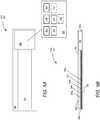
- FIG. 5A a top-view is shown of an example of an implementation of the WTD 500 as a security tape or security label type of device (i.e., a "Band-Aid" type of device) in accordance with the present disclosure.
- the encapsulation material 502 may be in the shape of tape or label including part, or all, of the multi-layer probe 504 within the encapsulation material 502.
- the multi-layer probe 504 may be a multi-layered device that includes a plurality of material layers (i.e., multiple layers of material) within the multi-layer prober 504 that may include a wire, electrical substrate, or other electrically conductive material.
- the multi-layer probe 504 may include two or more layers of material placed together that cause the multi-layer probe 504 to have predetermined electrical characteristics that may include, for example, a predetermined impedance, capacitance, inductance, dielectric properties, breakdown voltage, etc.
- the WTD 500 may utilize these changed electrical characteristics to identify a triggering event corresponding to a tampering event as experienced by the multi-layer probe 504.
- the multi-layer probe 504 may also include multiple layers within the multi-layer probe 504 where one or more layers may include one or more electrical probes such as conductive strips or wires.
- the encapsulation material 502 that may include, for example, paper, cloth, elastomer, nitrile, fluorosilicone, fluoroelastomer, neoprene, silicone, EPDM rubber, fabric, polymeric material, ceramic, thin metal, or other material.
- the encapsulation material 502 may be referred to as a sensor external substrate.
- the encapsulation material 502 includes an electronic portion 506 of the WTD 500 that includes the transmitter 302, receiver 312, antenna 310, processing device 306, power supply, and part of the multi-layer probe 504.
- the encapsulation material 502 may also include the optional sensor 314 and optional trigger switch 336.
- the electronic portion 514 includes the power supply 308 and a system on a chip ("SOC"), ASIC, FPGA, or a substrate or printed circuit board (“PCB”) having the transmitter 302, receiver 312, antenna 310, and processing device 306.
- the WTD 500 detects tampering (i.e., a physical trigger) via deformation, damage, or break of the multi-layer probe 504.
- the multi-layer probe 504 is shown to have five (5) layers of material 504a, 504b, 504c, 504d, and 504e.
- This number of layers of material is for illustration purposes only and it is appreciated by those of ordinary skill in the art that they number of layers can vary based on the design from a minimum of two (2) to any number determined by the design.
- the lower layer 504e may be support layer that supports the electronic portion 506 and the remaining layers of the multi-layer probe 504.
- the lower layer 504e may include an attachment surface 508 at the bottom of the WTD 500 that attaches to the surface to be monitored.
- the attachment surface 508 may include any attachment means that will properly attach the attachment surface 508 to the surface to be monitored and may include an adhesive.
- FIG. 5B a side-view is shown of an example of the implementation of the WTD 500 in accordance with the present disclosure. It is appreciated by those of ordinary skill in the art that the WTD 500 illustrated in FIGs. 5A and 5B are not so scale and for illustration purpose only. As such, the relative size and dimensions of the multi-layer probe 504, electronic portion 506, and encapsulation material 502 may vary based on the design of the WTD 500.
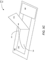
- FIG. 5C a prospective-view is shown of the WTD 500 where a trigger event (i.e., a tamper) has occurred in accordance with the present disclosure.
- a trigger event i.e., a tamper
- the first layer of material 504a of the multi-layer probe 504 has been substantially altered (i.e., damaged) to the point of being peeled off from the second layer of material 504b in a peeling direction 510.
- the physical trigger is a separating of the layers of the material within the multi-layer probe 504.
- any deformation or damage of the multi-layer probe 504 is also applicable in this example and large separation of the first layer of material 504a from the second layer of material 504b (as an example of break or extensive damage of the multi-layer probe 504) is shown for purposes of ease of illustration. Moreover, the separation, deformation, or damage may be between any of the layers of material 504a, 504b, 504c, 504d, or 504e.
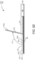
- FIG. 5D a side-view is shown of the WTD 500 where the trigger event has occurred in accordance with the present disclosure.
- FIG. 6A a block system diagram is shown of an example of an implementation of the WTD 600 as a flat rectangular Band-Aid type of device (i.e., a security tape or security label type of device) in accordance with the present disclosure.
- This example is similar to the one described in FIGs. 5A through 5D , with the addition of having conductive wire or strip within the multi-layer probe 602 that may be part of any of the multiple layers of material 504a, 504b, 504c, 504d, or 504e shown in FIGs. 5A through 5D .
- the encapsulation material 604 is in the shape of a large rectangular flat Band-Aid.
- the multi-layer probe 602 extends throughout the encapsulation material 604 in a turning fashion that fills a multi-layer probe area 606 along a first portion of the encapsulated material 604.
- the multi-layer probe 602 may (as discussed earlier) include multiple layers of material and an electrical wire or strip 603 (or other electrically conductive material with the proper performance properties of current, resistance, capacitance, voltage, etc.) that is of sufficient thickness to detect any tampering along the multi-layer probe area 606.
- the multi-layer probe 602 extends outward from a first end 608 of an electronic portion 610 to a second end 612 of the electronic portion 610 via the electrical wire or strip 603 or other conductive material layers within the multi-layer probe 602.
- the multi-layer probe 602 may include the continuous electrical wire or strip 603 that forms a closed circuit within the WTD 600 such that a current 614 flows from and to the electronic portion 610 when the multi-layer probe 602 is untampered.
- the electronic portion 610 is part of the encapsulation material 604 and includes the transmitter 302, receiver 312, antenna 310, processing device 306, power supply, and part, or all, of the multi-layer probe 602.
- the electronic portion 610 may also include the optional sensor 314 and optional trigger switch 336.
- the electronic portion 610 includes the power supply 308 and a SOC, ASIC, FPGA, or a substrate or PCB having the transmitter 302, receiver 312, antenna 310, and processing device 306.
- the WTD 600 detects tampering (i.e., a physical trigger) via a deformation, damage, or break in the multi-layer probe 602 along the multi-layer probe area 606 within the multi-layer probe 602.
- the deformation, damage, or break in the multi-layer probe 602 may include a break in the electrical wire or strip 603.
- the multi-layer probe 602 Prior to any tampering activity, the multi-layer probe 602 is continuous and undamaged.
- the WTD 600 is attached to a surface (or across multiple surfaces) and detects when there has been physical separation from the attaching surface or surfaces that causes deformation, damage, or a break of the multi-layer probe 602.
- the WTD 600 can attach to a flat surface (e.g., utilizing the attachment surface 508), it is appreciated that in this example the electronic portion 610 is at one end of the WTD 600 such that the WTD 600 can be utilized for a corner application.
- the WTD 600 receives wake command from an external device that is authenticated as an authenticated interrogator by the WTD 600 performing a series of predetermined security protocols. As described earlier, in another example, the wake command may not cause the WTD 600 to set the tampered state to untampered.
- the WTD 600 transmits a tamper state back to the interrogator (i.e., the external device). More specifically, the WTD 600 may first authenticate, then check the current state of the tamper, write and/or compile a report, and transmit the tamper state to the interrogator.
- the WTD 600 may either send back a tamper state signal indicating that the tamper state of the WTD 600 is "tampered," or the WTD 600 will not send back the tamper state signal at all.
- the multi-layer probe 602 and antenna 310 may be the same element and as such when the multi-layer probe 602 is broken the antenna 310 will be broken and have a shorted antenna length causing the WTD 600 to send back and altered (i.e., frequency shifted) tamper state signal.
- the damage to the multi-layer probe 602 may be such that the WTD 600 is incapable of transmitting the tamper state signal.
- the multi-layer probe 602 and antenna 310 are the same an too damaged to transmit the tamper state signal or the multi-layer probe 602 is separate from the antenna 310 but once the multi-layer probe 602 is broken the current 614 flow within the WTD 600 is interrupted and the disables the operation of the WTD 600.
- the WTD 600 is simply designed to transmit the tamper state signal to the external device only when the WTD 600 is untampered but once tampered, the WTD 600 stops transmitting the tamper state signal.
- the WTD 600 provides both a wireless and visual indication of tamper evidence.
- FIG. 6B a block system diagram is shown of the WTD 600 after being tampered in accordance with the present disclosure.
- the physical trigger 616 is shown as a fissure along the multi-layer probe 602 via the electrical wire or strip 603.
- the electrical wire or strip 603 is utilized to detect the tamper; however, alternatively the multi-layer probe 602 may not include an electrical wire or strip 603 an may utilize at least one conductive layer within the multi-layer probe 602 that conducts the current 614 along the at least one conductive layer from the first end 608 of an electronic portion 610 to the second end 612 of the electronic portion 610.
- the physical trigger 616 may be a deformation, damage, or break (i.e., a fissure) along the multi-layer probe 602 that has multiple layers of material without the electrical wire or strip 603.
- any tampering would result in the deformation, damaging, or breaking of the at least one conductive layer, the other non-conductive dielectric layers, or both that would change the electrical characteristics of the multi-layer probe 602 from the original predetermined electrical characteristics.
- This change in electrical characteristics may be detected by the electronic portion 610 of the WTD 600 and flagged as a tampering event indicative of the physical trigger 616.
- the physical trigger 616 may be a peeled off type of damage similar to the one described with regards to FIGs. 5C and 5D .
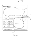
- FIG. 7A a block system diagram is shown of an example of an implementation of the WTD 700 as a hybrid type of device in accordance with the present disclosure.
- the encapsulation material 702 may be in the shape of a flat sheet that has a first axis 704 and a second axis 706 that divide up the flat sheet into a first quadrant 708, second quadrant 710, third quadrant 712, and fourth quadrant 714.
- the power supply 308 and other electronics reside in one quadrant (i.e., the first quadrant 708) of the WTD 700 to provide corner or cross surface applications for the WTD 700.
- the encapsulation material 702 includes the multi-layer probe 716 that is in portions of all four quadrants 708, 710, 712, and 714 and an electronics portion 718 of the WTD 700 that includes the transmitter 302, receiver 312, antenna 310, processing device 306, power supply 308, and part of the multi-layer probe 716.
- the portions of all four quadrants 708, 710, 712, and 714 that include the multi-layer probe 716 are shown as a multi-layer probe area 719 that extends out of the electronics portion 718.
- the electronics portion 718 may also include the optional sensor 314 and optional trigger switch 336.
- the electronics portion 718 includes the power supply 308 and a SOC, ASIC, FPGA, or a substrate or PCB having the transmitter 302, receiver 312, antenna 310, and processing device 306.
- the multi-layer probe 716 may include an electrical wire or strip 717 (or other electrically conductive material with the proper performance properties of current, resistance, capacitance, voltage, etc.) that is of sufficient thickness to detect any tampering along a multi-layer probe area 719 and is part of all four quadrants 708, 710, 712, and 714.
- the multi-layer probe 716 is shown to extend outward from a first end 720 of the electronics portion 718 to a second end 722 of the electronics portion 718.
- the multi-layer probe 716 may include the continuous electrical wire or strip 717 that forms a closed circuit within the WTD 700 such that a current 724 flows from and to the WTD 700 when the multi-layer probe 716 is untampered.
- the multi-layer probe 716 and antenna 310 may be the same element.
- the WTD 700 detects tampering (i.e., a physical trigger) via deformation, damage, or a break 726 (i.e., a fissure) in the multi-layer probe 716 along the multi-layer probe area 719, which is a break or rip 728 in the encapsulation material 702 and a break 726 in the multi-layer probe 716 (that may include a break in the electrical wire or strip 717) along one of the axis 704 and 706.
- the break 726 may be a peeled off type of damage similar to the one described with regards to FIGs. 5C and 5D .
- the WTD 700 may or may not include the electrical wire or strip 717 shown.
- the multi-layer probe 716 may include multiple layers of material that include at least one conductive layer that is in contact with the first end 720 of the electronics portion 718 to a second end 722 of the electronics portion 718 and electronics portion 718 is configured to detect a tampering event along the multi-layer probe 716.
- the WTD 700 receives wake command from an external device that is authenticated as an authenticated interrogator by the WTD 700 performing a series of predetermined security protocols. As described earlier, in another example, the wake command may not cause the WTD 700 to set the tampered state to untampered.
- the WTD 700 transmits a tamper state back to the interrogator (i.e., the external device). More specifically, the WTD 700 may first authenticate, then check the current state of the tamper, write and/or compile a report, and transmit the tamper state to the interrogator.
- the WTD 700 may either send back a tamper state signal indicating that the tamper state of the WTD 700 is "tampered," or the WTD 700 will not send back the tamper state signal at all.
- the multi-layer probe 716 and antenna 310 may be the same element and as such when the multi-layer probe 716 is broken the antenna 310 will be broken and have a shorted antenna length causing the WTD 700 to send back an altered (i.e., frequency shifted) tamper state signal.
- the damage to the multi-layer probe 716 may be such that the WTD 700 is incapable of transmitting the tamper state signal.
- the multi-layer probe 716 and antenna 310 are the same an too damaged to transmit the tamper state signal or the multi-layer probe 716 is separate from the antenna 310 but once the multi-layer probe 716 is broken the current 724 flow within the WTD 700 is interrupted and the disables the operation of the WTD 700.
- the WTD 700 is simply designed to transmit the tamper state signal to the external device only when the WTD 700 is untampered but once tampered, the WTD 700 stops transmitting the tamper state signal.
- the WTD 700 provides both a wireless and visual indication of tamper evidence.
- FIG. 7B a block system diagram is shown of the WTD 700 after being tampered in accordance with the present disclosure.
- the physical trigger 726 is shown as a fissure along the multi-layer probe 716 along a rip 728 in the encapsulation material 702.
- the encapsulation material 802 may be in the shape of a flat rectangular sheet that includes part of the antenna 804 within an antenna area 806 of the encapsulation material 802.
- the antenna 804 extends through the antenna area 806 in a manner that fills the antenna area 806.
- an electronics portion 808 that includes the power supply 308 and a SOC, ASIC, FPGA, or a substrate or PCB having the transmitter 302, receiver 312, accelerometer 315, and the processing device 306.
- the electronics portion 808 may also include the optional trigger switch 336.
- the antenna 804 is shown extending outward from a first end 810 of the electronics portion 808 to an optional second end 812 of the electronics portion 808.
- the antenna 804 may be a wire, foil, or electro-deposited metal.
- the antenna 804 may be an electrical wire, strip, or a conductive layer of material within a multi-layer probe 814.
- the WTD 800 detects tampering (i.e., a physical trigger) via the accelerometer 315.
- the accelerometer 315 is designed to detect a physical trigger based on movements or vibrations on the WTD 800. Because the internal and external components of the WTD 800 are not altered after a physical trigger (i.e., the WTD 800 is not broken or damaged), the WTD 800 is resettable and can detect multiple physical triggers (i.e., tamper events) throughout its design life.
- the WTD 800 receives wake command from an external device that is authenticated as an authenticated interrogator by the WTD 800 performing a series of predetermined security protocols. As described earlier, in another example, the wake command may not cause the WTD 800 to set the tampered state to untampered.
- the WTD 800 transmits a tamper state back to the interrogator (i.e., the external device). More specifically, the WTD 800 may first authenticate, then check the current state of the tamper, write and/or compile a report, and transmit the tamper state to the interrogator.
- the WTD 800 may either send back a tamper state signal indicating that the tamper state of the WTD 800 is "tampered," or the WTD 800 will not send back the tamper state signal at all. In the case of not sending back the tamper state signal, the WTD 800 may simply be designed to transmit the tamper state signal to the external device only when the WTD 800 is untampered but once tampered, the WTD 800 stops transmitting the tamper state signal.
- the WTD 800 Since the WTD 800 is not damaged by detecting the physical trigger, after the physical trigger has been detected, the WTD 800 may be reset to an untampered state for reuse in detecting another physical trigger.
- the WTD 800 may be reset by receiving a reset signal from the external device after the WTD 800 was placed in a tampered state; the WTD 800 may then be reutilized.
- the WTD 800 may also be reset by a user again activating the optional trigger switch 336.
- each block in the flowchart or block diagrams may represent a module, a segment, a function, a portion of an operation or step, some combination thereof.
- the function or functions noted in the blocks may occur out of the order noted in the figures.
- two blocks shown in succession may be executed substantially concurrently, or the blocks may sometimes be performed in the reverse order, depending upon the functionality involved.
- other blocks may be added in addition to the illustrated blocks in a flowchart or block diagram.
Landscapes
- Engineering & Computer Science (AREA)
- Physics & Mathematics (AREA)
- General Physics & Mathematics (AREA)
- Computer Security & Cryptography (AREA)
- Theoretical Computer Science (AREA)
- Burglar Alarm Systems (AREA)
- Arrangements For Transmission Of Measured Signals (AREA)
Abstract
Description
- The present disclosure is related to sensors, and in particular, to sensors that detect tampering.
- In commercial travel there is a need to screen and secure items placed within storage areas of many commercial vehicles such as, for example, aircraft, buses, ships, trains, or trucks. Additionally, within commercial aircraft, buses, trains, and ships, there may be cabins, closets, pallets, and rooms that need to be kept closed and secure, such as maintenance areas.
- In many of these situations, physically locking a specific area may not be an option. For example, the bins above passengers, washrooms, and galleys in a commercial airliner train or bus may need to be easily accessible at one point or another while traveling. As another example, the washrooms in a vehicle may need to be inspected, secured, and closed prior to passengers boarding the vehicle for security purposes. Similarly, in an aircraft, crew related items may need to be stored in an overhead bin or closet that also needs to be closed and secured. Moreover, storage compartments in a galley may also need to be inspected, closed, and secured.
- At present, the approach to securing these areas is generally limited to inspecting, closing, and placing a device at the access of the area that may be a door or flap. Examples of the device may include multiple devices or items that provide visual evidence of tamper, such as, for example, a zip tie, an adhesive seal or tape, and a plastic padlock that are permanently altered or broken by a tamper event. For example, in
FIG. 1 , a system block diagram of an example of an implementation of a knownsecurity seal 100 is shown attached to anoverhead bin door 102 of an overhead bin 104. The overhead bin 104 may be located within an aircraft, bus, train, or other passenger vehicle. Thesecurity seal 100 is located on both theoverhead bin body 106 and theoverhead bin door 102 in a straddling fashion that bridges thegap 108 between theoverhead bin body 106 and theoverhead bin door 102. - Turning to
FIG. 2 , a system block diagram of an example of another implementation of aknown security device 200 is shown attached to asecure box 202. Again, thesecure box 202 may be located within an aircraft, bus, train, or other passenger vehicle. Thesecurity device 200 may be a padlock type device, zip tie, adhesive seal or tap, or other similar device. Thesecurity box 202 may be a storage location having alid 204 that is utilized to store secure items that include, for example, crew items and/or emergency equipment, life vest(s), fire extinguisher, automated external defibrillator ("AED"), etc. In this example, thesecurity device 200 may be a padlock type device that attaches to anattachment device 206 that is located on both thelid 204 and afront wall 208 of thesecurity box 202 in a straddling fashion that bridges agap 210 between thefront wall 208 and thelid 204. - In both examples, if either the
overhead bin door 102 orsecurity box 202lid 204 is opened, thecorresponding security seal 100 orsecurity device 200 will be physically and visibly damaged indicating that someone opened (or attempted to open) either theoverhead bin door 102 orlid 204. Generally, the security seals (such assecurity seal 100 or security device 200) are a type of tape or device that are usually known as, for example, tamper seals, security seals, tamper evident security seals, security tapes, tamper evident tapes, plastic zip ties, or padlocks, which for the purpose of simplicity are herein referred to as "security seals" or "security devices." In general, these security seals or devices are designed to be visually inspected and easily recognized if tampered with or broken. As an example, security seals or devices are utilized in commercial aircraft to help ensure that any items placed onto the aircraft have been cleared by the relevant security personnel, and once cleared, those items are sealed to make sure that they cannot be tampered with before, during and post flight. - Unfortunately, while useful, these types of security seals or devices require the relevant security personal or crew member to walk through the vehicle and visually, and possibly physically, inspect each security seal or device individually to see if it has been tampered. As a result, this leads to downtime of the vehicle and increased manual labor costs related to the physical inspection of all of the security seals or devices on the vehicle. Therefore, there is a need for a system and method that addresses the limitations of the known security seals and devices.
- A wireless tamper device ("WTD") is disclosed. The WTD includes a transmitter, multi-layer probe, processing device, and power supply. The processing device is in signal communication with the multi-layer probe and the power supply is in signal communication with the transmitter and processing device. The processing device includes a processor and a computer-readable medium ("CRM"). The CRM has encoded thereon computer-executable instructions to cause the processor to initiating a tamper state to untampered, detect a physical trigger on the multi-layer probe, and set the tamper state to tampered in response to detecting the physical trigger.
- In an example of operation, the WTD performs a method that includes initiating a tamper state to untampered, detecting a physical trigger, and setting the tamper state to tampered in response to detecting the physical trigger.
- Other devices, apparatus, systems, methods, features and advantages of the invention will be or will become apparent to one with skill in the art upon examination of the following figures and detailed description. It is intended that all such additional systems, methods, features and advantages be included within this description, be within the scope of the invention, and be protected by the accompanying claims.
- The invention may be better understood by referring to the following figures. The components in the figures are not necessarily to scale, emphasis instead being placed upon illustrating the principles of the invention. In the figures, like reference numerals designate corresponding parts throughout the different views.
-
FIG. 1 is a system block diagram of an example of an implementation of a known security seal attached to an overhead bin door of an overhead bin. -
FIG. 2 is a system block diagram of an example of another implementation of a known security device attached to a security box. -
FIG. 3 is a system block diagram of an example of an implementation of a wireless tamper device ("WTD") in accordance with the present disclosure. -
FIG. 4 is a flowchart of an example of an implementation of the method performed by the WTD, shown inFIG. 3 , in accordance with the present disclosure. -
FIG. 5A is a top-view of an example of an implementation of the WTD as a security tape or security label type of device in accordance with the present disclosure. - In
FIG. 5B is a side-view of an example of the implementation of the WTD, shown inFIG. 5A , in accordance with the present disclosure. -
FIG. 5C is a prospective-view of the WTD, shown inFIGs. 5A and 5B , where a trigger event has occurred in accordance with the present disclosure. -
FIG. 5D is a side-view of the WTD, shown inFIG. 5C , where the trigger event has occurred in accordance with the present disclosure. -
FIG. 6A is a block system diagram of an example of an implementation of the WTD, shown inFIG. 3 , as a flat "Band-Aid" type of device in accordance with the present disclosure. -
FIG. 6B is a block system diagram of the WTD, shown inFIG. 6A , after being tampered in accordance with the present disclosure. -
FIG. 7A is a block system diagram of an example of an implementation of the WTD, shown inFIG. 3 , as a hybrid type of device in accordance with the present disclosure. -
FIG. 7B is a block system diagram of the WTD, shown inFIG. 7A , after being tampered in accordance with the present disclosure. -
FIG. 8 is a block system diagram of an example of an implementation of the WTD, shown inFIG. 3 , which is resettable in accordance with the present disclosure. - Disclosed is a wireless tamper device ("WTD"). The WTD includes a transmitter, multi-layer probe having predetermined electrical characteristics, processing device, and power supply. The processing device is in signal communication with the multi-layer probe and the power supply is in signal communication with the transmitter and processing device. The processing device includes a processor and a computer-readable medium ("CRM"). The CRM has encoded thereon computer-executable instructions to cause the processor to initiate a tamper state to untampered, detect a physical trigger on the multi-layer probe, and set the tamper state to tampered in response to detecting the physical trigger. As such, in an example of operation, the WTD performs a method that includes initiating a tamper state to untampered, detecting a physical trigger, and setting the tamper state to tampered in response to detecting the physical trigger.
- In
FIG. 3 , a system block diagram is shown of an example of an implementation of theWTD 300 in accordance with the present disclosure. TheWTD 300 includes atransmitter 302,multi-layer probe 304,processing device 306, and apower supply 308. TheWTD 300 may also include anantenna 310,receiver 312,optional sensor 314, and optional accelerometer 315 (or other solid-state electronic sensor capable of measuring movement and/or vibration). In this example, theprocessing device 306 is in signal communication with thetransmitter 302,receiver 312,power supply 308,optional sensor 314, and theoptional accelerometer 315 viasignal paths power supply 308 is in signal communication with thetransmitter 302,receiver 312, and theoptional sensor 314 viasignal paths antenna 310 is in signal communication with thetransmitter 302 andreceiver 312 viasignal paths multi-layer probe 304 is in signal communication with theoptional sensor 314 viasignal path 334 and theprocessing device 306 via theoptional sensor 314 and signalpaths WTD 300 may optionally also include anoptional trigger switch 336 in signal communication with theprocessing device 306 viasignal path 338. Theoptional accelerometer 315 may be in signal communication with themulti-layer probe 304 viasignal path 339. - In this example, the
processing device 306 may include aprocessor 340 and a computer-readable medium ("CRM") 342. In general, theCRM 342 has encoded thereon computer-executable instructions to cause theprocessor 340 to perform different functions in the operation of theWTD 300. Theprocessor 340 may be any microprocessor or similar device, such as, for example, a central processing unit ("CPU"), digital signal processing ("DSP") device, application specific integrated circuit ("ASIC"), or a field programmable-gate array ("FPGA"). In general, theCRM 342 may be software or firmware and the computer-executable instructions stored on theCRM 342 may include, for example, an operating system, software, and other modules, programs, or applications that are loadable and executable byprocessor 340. Moreover, in the example of theCRM 342 being firmware, the computer-executable instructions may include hardware logic (i.e., machine instructions) that controls the operation of theprocessor 340. In this example, theCRM 342 may be in signal communication with theprocessor 340 via a signal path that includes a bus. - The
power supply 308 may be a battery configured to power theWTD 300 for an extended period of time. It is appreciated by those of ordinary skill in the art that thetransmitter 302 andreceiver 312 may be independent devices or combined together to form part of a transceiver. Themulti-layer probe 304 may be any type of multi-layer device capable of detecting a physical force (i.e., a physical trigger) associated with a tampering activity where the physical trigger may include physically damaging or breaking themulti-layer probe 304. Examples of themulti-layer probe 304 include multiple layers of material that may include a wire, electrical substrate, or other electrically conductive material. In general, themulti-layer probe 304 may include two or more layers of material placed together that cause themulti-layer probe 304 to have predetermined electrical characteristics that may include, for example, a predetermined impedance, capacitance, inductance, dielectric properties, breakdown voltage, etc. Once tampered, themulti-layer probe 304 may be physically modified or damaged such that the layers of material within themulti-layer probe 304 partially or fully move or separate from each other in a way that substantially alters and changes the electrical characteristics of themulti-layer probe 304 from the original predetermined electrical characteristics. - In general, the
multi-layer probe 304 is an electrical implementation of a security device similar to, for example, a security tape (also known as security label) that is a type of adhesive tape used to detect tampering. In general, security tape is a pressure sensitive tape or label with special tamper resistant or tamper evident features. These special tamper resistant or tamper evident features may include intentionally weak or frangible components that easily fracture or tear, printing which, when cut or torn, cannot easily be realigned, layers that easily delaminate to show entry or tampering, hidden print layers which indicated an opening or tampering, etc. In this example, themulti-layer probe 304 may also include special tamper resistant or tamper evident features that allow theWTD 300 to indicate that theWTD 300 has been tampered with. Themulti-layer probe 304 may include multiple layers of material that are sandwiched together to form themulti-layer probe 304. As an example, some of these layers may be electrically conductive and some may be isolative that act as a dielectrics between the electrically conductive layers. In an example of operation, a current may be induced to flow between the electrically conductive layers and through the dielectric layers between the electrically conductive layers. Without a tampering event, themulti-layer probe 304 may have predetermined electrical characteristics that lets themulti-layer probe 304 allow a certain amount of current to flow through themulti-layer probe 304 with a corresponding predetermined voltage drop across the inputs to themulti-layer probe 304. Moreover, in this example, themulti-layer probe 304 may have a predetermined impedance value corresponding to combination of resistive, capacitive, and inductive properties of themulti-layer probe 304. If themulti-layer probe 304 is then tampered (i.e., experiences a tampering event also referred to as a physical trigger associated with the tampering activity) that causes the movement, displacement, or damage of one or more layers of themulti-layer probe 304, this tamper will cause a physical variation or deformation of the layers within themulti-layer probe 304 that may change the distance, orientation, or both, between the electrically conductive layers and deformation or damage to the dielectric layers. As an example, this tamper may introduce cracks, breaks, and air gaps within layered structure of themulti-layer probe 304. These changes will result in changes to resistance, capacitance, inductance, and possibly the effect dielectric properties of material layers within themulti-layer probe 304 that cause themulti-layer probe 304 to have new electrical characteristics that are different than the original predetermined electrical characteristics. As such, theWTD 300 may utilize these changed electrical characteristics to identify a triggering event corresponding to a tampering event as experienced by themulti-layer probe 304. - As another example, the
multi-layer probe 304 may include multiple layers within themulti-layer probe 304 where one or more layers may include one or more electrical probes such as conductive strips or wires. In this example, the one or more electrical probes may include just one electrical wire or strip within themulti-layer probe 304 that is electrically connected to other devices of theWTD 300 and completes a circuit that passes a predetermined amount of current and has predetermined electrical characteristics. Alternatively, two or more electrical wires or strips may be utilized where the two or more electrical wires or strips interact with each other, e.g., one electrical wire or strip may act as an input to themulti-layer probe 304 while another electrical wire or strip may act as an output to themulti-layer probe 304. In this example, the first electrical wire or strip may be in signal communication with the second electrical wire or strip through the other dielectric layers of themulti-layer probe 304. - In this example, if the
multi-layer probe 304 is then tampered in a way that causes the movement, displacement, or damage of one or more layers of themulti-layer probe 304, this tamper will cause a physical variation or deformation of the layers within themulti-layer probe 304 that may change the distance, orientation, or both, between the electrically wires or strips and deformation or damage to the dielectric layers. Moreover, the tamper may also damage or break one or more of the electrical wires or strips. As described earlier, this tamper may introduce cracks, breaks, and air gaps within layered structure of themulti-layer probe 304. These changes will result in changes to resistance, capacitance, inductance, and possibly the effect dielectric properties of material layers within themulti-layer probe 304 that cause themulti-layer probe 304 to have new electrical characteristics that are different than the original predetermined electrical characteristics. As such, theWTD 300 may utilize these changed electrical characteristics to identify a triggering event corresponding to a tampering event as experienced by themulti-layer probe 304. - Also as yet another example, the
antenna 310 may be themulti-layer probe 304. In other words, theantenna 310 andmulti-layer probe 304 may be the same element (i.e., device, component, module, or circuit) where theantenna 310 may have an antenna length that is approximately equal to a fractional length (such as, for example, a half-wavelength) of an operating frequency of operation of thetransmitter 302 andreceiver 312. In this example, the physical trigger may be a damaging or breaking of theantenna 310 that results in the reduction of the antenna length. It is appreciated by those of ordinary skill in the art that changing the antenna length of theantenna 310 will alter the electrical properties of theantenna 310 that include, for example, causing theantenna 310 to operate at a new shifted frequency (i.e., it will result in a new operating frequency that is equal to the new reduced antenna length of theantenna 310 after the breakage or damage of theantenna 310 by the tampering activity), be less efficient at receiving and transmitting signals at the original frequency of operation of thetransmitter 302 and receiver 312 (i.e., the quality of reception and transmission will be degraded), and changing the input impedance of theantenna 310. - In some implementations the
WTD 300 may not have anoptional sensor 314 and themulti-layer probe 304 will be in direct signal communication (i.e., directly connected) to theprocessing device 306, where theprocessing device 306 will include a module or logic capable of sensing the physical trigger associated with the tampering activity. As described earlier, theWTD 300 may optionally include theoptional sensor 314 or not because themulti-layer probe 304 may be in direct signal communication withprocessing device 306. However, if present, theoptional sensor 314 may be a device, component, module, or circuit configured to sense the physical trigger on themulti-layer probe 304. If theoptional trigger switch 336 is included in theWTD 300, theoptional trigger switch 336 may be a user activated switch that arms theWTD 300 to detect the physical trigger on themulti-layer probe 304 by initiating a tamper state of theWTD 300 to "untampered." - In addition to, or instead of, the
optional sensor 314, the WTD may also optionally include theoptional accelerometer 315. An accelerometer is a device that measures the proper acceleration of the device, which is a rate of change of velocity of the device in its own instantaneous rest frame (i.e., measures movements or vibrations of the device). If present in theWTD 300, theoptional accelerometer 315 detects any movement or vibration (which is a very small movement that is an oscillating, reciprocating, or other periodic type of motion) as the physical trigger. - In this example, the
entire WTD 300 may be partially or completely enclosed by anencapsulation material 344 that may include, for example, paper, cloth, elastomer, nitrile, fluorosilicone, fluoroelastomer, neoprene, silicone, ethylene propylene diene monomer ("EPDM") rubber, fabric, polymeric material, ceramic, thin metal, or other material. In general, theencapsulation material 344 may be referred to as a sensor external substrate. - It is appreciated by those skilled in the art that the circuits, components, modules, and/or devices of, or associated with, the
WTD 300 are described as being in signal communication with each other, where signal communication refers to any type of communication and/or connection between the circuits, components, modules, and/or devices that allows a circuit, component, module, and/or device to pass and/or receive signals and/or information from another circuit, component, module, and/or device. The communication and/or connection may be along any signal path between the circuits, components, modules, and/or devices that allows signals and/or information to pass from one circuit, component, module, and/or device to another and includes wireless or wired signal paths. The signal paths may be physical, such as, for example, conductive wires, electromagnetic wave guides, cables, attached and/or electromagnetic or mechanically coupled terminals, semi-conductive or dielectric materials or devices, or other similar physical connections or couplings. Additionally, signal paths may be non-physical such as free-space (in the case of electromagnetic propagation) or information paths through digital components where communication information is passed from one circuit, component, module, and/or device to another in varying digital formats without passing through a direct electromagnetic connection. - In general, as an example of operation, the computer-executable instructions of the
CRM 342 will cause theprocessor 340 to initiate a tamper state to untampered, detect a physical trigger on themulti-layer probe 304, and set the tamper state to tampered in response to detecting the physical trigger. In this example, the computer-executable instructions of theCRM 342 may initiate the tamper state to untampered either by a user arming theWTD 300 via theoptional trigger switch 336 or by receiving a "wake" command from an external device in signal communication with theWTD 300. The external device may be a server, user portable device, or other wireless device capable of interfacing with theWTD 300. In this example, the term "arming" or "armed" is utilized to designate that theWTD 300 is placed in a state that detects any tampering on theWTD 300 by either moving or damaging theWTD 300. - If the
WTD 300 is armed by an external device, the computer-executable instructions of theCRM 342 will cause theprocessor 340 to receive the wake command from the external device and then authenticate the wake command. It is appreciated by those of ordinary skill in the art that the wake command may be authenticated by a process that includes determining that the external device is an "authenticated interrogator" by utilizing a series of predetermined security protocols. Once the wake command is authenticated, the computer-executable instructions of theCRM 342 then causes theprocessor 340 to initiate the tamper state to untampered. In this example, it is assumed that the tamper state of theWTD 300 is in a state that is not "untampered" but may not be in a state that is "tampered;" however, it is also appreciated that the state of theWTD 300 may vary based on the design of theWTD 300. - In another example, it is appreciated by those of ordinary skill in the art that setting the state to untampered may involve more than only receiving the wake command. The wake command may include instructions to set the tamper state to untampered, or, other instructions. Specifically, receiving the wake command may be for initial setup only where the
WTD 300 may initially be running in a lower power scheme where theWTD 300 is in a dormant state for several seconds, powers up theprocessor device 306 for a short time (for example, a few milliseconds) to listen to thereceiver 312 for an authenticated command signal that may be an independent signal from the initial wake command. In this example, the wake command may only cause theprocessing device 306 to query thereceiver 312 for a wake package of information for what operation is being requested, which may include to set the state to untampered, or to query theWTD 300 state and then send a report, or possibly other encoded functionality at theprocessing device 306. In the case of authenticated command signal, once authenticated theprocessing device 306 may further execute instructions that may set the initial state of theWTD 300 to untampered, to read the sensor current state, read the power level remaining, generate a report, instruct to transmit, or other instructions. In another example, the wake command may also act as a "reset" function to place theWTD 300 into the untampered state. - For example, the
WTD 300 may include an "off' state prior to being deployed and initiating the tamper state to untampered may include changing the off state to the untampered state by arming theWTD 300 either with theoptional trigger switch 336 or the wake command from the external device. Alternatively, theWTD 300 may only include two states (i.e., untampered and tampered) and initiating the tamper state to untampered may include powering up the components of theWTD 300 once the wake command is received and authenticated or the user arms theWTD 300 via theoptional trigger switch 336. In either example, theWTD 300 is armed by a user directly (via the optional trigger switch 336) or a user wirelessly (via a wireless connection with the external device). - In yet another example, the
WTD 300 may be a resettable device capable of being reutilized after first use. In this example, theWTD 300 may have been first utilized in a situation that detected that theWTD 300 was tampered with by a physical trigger. As an example, theWTD 300 includes theoptional accelerometer 315 and theWTD 300 is utilized to monitor tampering of a door where theWTD 300 is placed on the door and armed. The door is subsequently moved causing the computer-executable instructions to cause theprocessor 340 to first detect the physical trigger (i.e., the movement of the door) on themulti-layer probe 304, which may be in signal communication with theoptional accelerometer 315, and then set the tamper state to tampered in response to detecting the physical trigger. However, since in this example the physical trigger is the movement of the door and the movement has not caused any damage to theWTD 300, theWTD 300 may be reset and utilized again either on the same door or in another application that needs to detect movement. In this example, theWTD 300 may not include the optional sensor 314 (because the sensor for movement is the optional accelerometer 315) nor a separatemulti-layer probe 304 that is independent from theoptional accelerometer 315 because themulti-layer probe 304 may be part of theoptional accelerometer 315 or an extension of it such as, for example, a mechanical filter (i.e., a vibration filter). In this example, once theWTD 300 is ready for reuse, theWTD 300 may receive a reset signal from the external device or the user may again activate theoptional trigger switch 336 that causes the computer-executable instructions to cause theprocessor 340 to reset the state of theWTD 300 back to untampered and theWTD 300 may again monitor the door for another physical trigger. - In operation, once the
WTD 300 has been triggered, theWTD 300 may, for example, transmit a tamper state signal in response to detecting the physical trigger, wait to receive a status command from the external device, or do nothing. In the first example, once tampered (i.e., a physical trigger was detected on themulti-layer probe 304 or the optional accelerometer 315) the computer-executable instructions cause theprocessor 340 to set the tamper state to tampered in response to detecting the physical trigger. The computer-executable instructions then cause theprocessor 340 to transmit a tamper state signal in response to detecting the physical trigger, where the tamper state signal indicates that the tamper state is tampered. In this example, thetransmitter 302 may transmit the tamper state signal as a beacon or other repetitive transmission to the external device. In this example, theantenna 310 may be a distinct element from themulti-layer probe 304 and themulti-layer probe 304 may have been broken or damaged. Alternatively, theoptional accelerometer 315 may be a combination of theoptional sensor 314 andmulti-layer probe 304 and thetransmitter 302 transmits the tamper state signal via theantenna 310. In another alternative, themulti-layer probe 304 is theantenna 310 and thetransmitter 302 transmits the tamper state signal via theantenna 310 that has been damaged or broken, which reduced the antenna length of theantenna 310. As a result, theantenna 310 receives the tamper state signal from thetransmitter 302 and transmits it at an altered frequency (as compared to the original operation frequency of the transmitter 302) because of the reduction of antenna length caused by the physically trigger. In all of these situations, theWTD 300 transmits the tamper state signal automatically after detecting the physical trigger. - In the second example, the
WTD 300 does not automatically transmit the tamper state signal when a physical trigger is detected. Instead, theWTD 300 waits to be queried by the external device as to its tamper status. When theWTD 300 receives a status command from the external device, the computer-executable instructions cause theprocessor 340 to receive the status command from the external device and transmit the tamper state signal in response to receiving the status command. Similar to the first example, in this example, theantenna 310 may be a distinct element from themulti-layer probe 304 and themulti-layer probe 304 may have been broken or damaged. Alternatively, theoptional accelerometer 315 may be a combination of theoptional sensor 314 andmulti-layer probe 304 and thetransmitter 302 transmits the tamper state signal via theantenna 310. In another alternative, themulti-layer probe 304 is theantenna 310 and thetransmitter 302 transmits the tamper state signal via theantenna 310 that has been damaged or broken reducing the antenna length of theantenna 310. As a result, theantenna 310 receives the tamper state signal from thetransmitter 302 and transmits it at a shifted frequency because of the reduction of antenna length caused by the physically trigger. In all of these situations, theWTD 300 transmits the tamper state signal only after detecting the physical trigger and receiving the status command from the external device. - In the third example, the
WTD 300 does nothing if a physical trigger is detected. In this example, once tampered the computer-executable instructions may cause theprocessor 340 to set the tamper state to tampered in response to detecting the physical trigger or do nothing. Specifically, once theWTD 300 is armed (either by theoptional trigger switch 336 or a wake command from an external device), theWTD 300 may be automatically placed in an untampered tamper state (i.e., theWTD 300 is armed and ready to detect a physical trigger). While in this untampered tamper state, theWTD 300 may either automatically transmit a tamper state signal as a beacon or other repetitive transmission to the external device or wait for a query from the external device before answering the query (i.e., the status command) with the tamper state signal. In this example, theWTD 300 may be in a sleep state, which will not check the tamper state until receiving an authenticated request for status, at which time theprocessing device 306 queries directly to theoptional sensor 314 to determine the state as tampered or untampered, after which WTD 300 immediately reports the state status to the external device. - In either case, once the physical trigger happens, the
WTD 300 may continue to transmit the tamper state signal either automatically or when queried or "go silent" and not transmit any tamper state signal. In these examples, there are three situations that may affect the ability of theWTD 300 to transmit the tamper state signal. In the first and second situations, theantenna 310 is themulti-layer probe 304 and it suffers damage from the physical trigger that either breaks or damages theantenna 310 but theantenna 310 is still functioning and able to transmit a signal. In these situations (as discussed earlier), theWTD 300 continues to transmit the same tamper state signal without changing the tamper state of the signal in theprocessor 340. As discussed earlier, in these cases theantenna 310 will alter the frequency of transmission of the tamper state signal because of the reduction of the antenna length. If the external device is configured to detect the change in transmitted frequency by theantenna 310, then there is no need to have theprocessor 340 change the tamper state of theWTD 300 since the tampering activity itself has caused an effective "change in state" since the resulting transmission of the tamper state signal will automatically shift in frequency based on the damage caused to theantenna 310 and the external device may be configured to detect that frequency shift and flag it as indicating that theWTD 300 has been tampered. As such, in these situations theWTD 300 does not need to do anything different once armed since the physical trigger has caused damage to theantenna 310 that causes a frequency shift that is detectable by the external device as a flag indicating that theWTD 300 has been tampered. - In the third situation, the damage to the
multi-layer probe 304 may be so great that theWTD 300 is not be able to transmit a tamper state signal thus indicating that theWTD 300 has been tampered. For example, if themulti-layer probe 304 is theantenna 310, the damage to theantenna 310 may be so great that theantenna 310 is not function and thus not capable of transmitting the tamper state signal. Since the external device is expecting a response from the WTD 300 (in response to the status command), the external device will flag theWTD 300 as tampered because no signal was received by the external device. Alternatively, theWTD 300 may be configured to always respond to a status command queried by the external device when in the untampered tamper state but once tampered (i.e., once the physical trigger is detected), theWTD 300 may simply stop transmitting any reply to the status command. Again, in this situation, since the external device is expecting a response from the WTD 300 (in response to the status command), the external device will flag theWTD 300 as tampered. - It is appreciated that in these examples, the
WTD 300 may be designed such that when the computer-executable instructions cause theprocessor 340 to initiate the tamper state to untampered, the computer-executable instructions are simply arming theWTD 300 for operation in detecting a physical trigger that will eventual move theoptional accelerometer 315 or damage the multi-layer probe 304 (which may be the antenna 310). This may include simply turning the power on for the components (i.e., thetransmitter 302,receiver 312,accelerometer 315,processing device 306,optional sensor 314, and multi-layer probe 304) of theWTD 300 so as to be able to detect the physical trigger. In this example, theWTD 300 is placed in a tampered tamper state automatically when the physical trigger happens because the physical trigger actually physically effects the WTD 300 (i.e., it moves or damages the WTD 300) in such a way that when the computer-executable instructions cause theprocessor 340 to set the tamper state to tampered in response to detecting the physical trigger, the computer-executable instructions are simply preparing theWTD 300 to transmit the tamper state signal either automatically or in response to receiving the status command. - Turning to
FIG. 4 , a flowchart is shown of an example of an implementation of themethod 400 performed by theWTD 300 in accordance with the present disclosure. Themethod 400 starts 402 by receiving an armingcommand 404. As described earlier, the arming command may be a command produced by a user activating theoptional trigger switch 336 or by receiving a wake command from the external device. If the arming command is the wake command from the external device, the arming command is then authenticated 406. The arming command then causes theWTD 300 to initiate the tamper state to untampered 408 as described earlier. TheWTD 300 is then armed and ready to detect a physical trigger. If no physical trigger is detected, theWTD 300 remains in the armed state and ready to detect the physical trigger. TheWTD 300 may then enter into a passive state that does not transmit anything until theWTD 300 receives an authenticated request for state status. Once the physical trigger is detected 410, theWTD 300 sets the tamper state to tampered 412 (as described earlier) in a fashion that may be the automatic result of the physical condition of the WTD 300 (as described earlier). TheWTD 300 may then either transmit atamper state signal 414 or wait for a status command (as described earlier) and then, in response, transmit thetamper state signal 414. In the case that theWTD 300 is an untampered state and there is no physical trigger detected 410, theWTD 300 may skip step 412 and optionally transmit atamper state 414 of "untampered." Alternatively, theWTD 300 may not transmit any signal as described earlier. Themethod 400 may then end 416. If theWTD 300 is resettable (i.e., theWTD 300 was not damaged and reusable as described earlier), themethod 400 may return to step 404, if theWTD 300 is reset, and wait for another arming command that may include a reset signal from the external device. If theWTD 300 is not reset, themethod 400 then ends 416. - In this example, the
WTD 300 utilizes energy to check for state of theWTD 300 and revise the state of theWTD 300 independent of the external query but in alternative example, theWTD 300 may only check for state once an authenticated status report command is received. Additionally, theWTD 300 may not transmit (i.e., send a state report) unless it receives an authenticated request to report the tamper state. Otherwise, theWTD 300 may cycle between dormant and listen-on-radio (i.e., monitor the receiver 312). - In
FIG. 5A , a top-view is shown of an example of an implementation of the WTD 500 as a security tape or security label type of device (i.e., a "Band-Aid" type of device) in accordance with the present disclosure. In this example, theencapsulation material 502 may be in the shape of tape or label including part, or all, of themulti-layer probe 504 within theencapsulation material 502. In this example and as described earlier, themulti-layer probe 504 may be a multi-layered device that includes a plurality of material layers (i.e., multiple layers of material) within themulti-layer prober 504 that may include a wire, electrical substrate, or other electrically conductive material. Themulti-layer probe 504 may include two or more layers of material placed together that cause themulti-layer probe 504 to have predetermined electrical characteristics that may include, for example, a predetermined impedance, capacitance, inductance, dielectric properties, breakdown voltage, etc. The WTD 500 may utilize these changed electrical characteristics to identify a triggering event corresponding to a tampering event as experienced by themulti-layer probe 504. Themulti-layer probe 504 may also include multiple layers within themulti-layer probe 504 where one or more layers may include one or more electrical probes such as conductive strips or wires. - In this example, the
encapsulation material 502 that may include, for example, paper, cloth, elastomer, nitrile, fluorosilicone, fluoroelastomer, neoprene, silicone, EPDM rubber, fabric, polymeric material, ceramic, thin metal, or other material. In general, theencapsulation material 502 may be referred to as a sensor external substrate. - In this example, the
encapsulation material 502 includes anelectronic portion 506 of the WTD 500 that includes thetransmitter 302,receiver 312,antenna 310,processing device 306, power supply, and part of themulti-layer probe 504. Theencapsulation material 502 may also include theoptional sensor 314 andoptional trigger switch 336. In this example, the electronic portion 514 includes thepower supply 308 and a system on a chip ("SOC"), ASIC, FPGA, or a substrate or printed circuit board ("PCB") having thetransmitter 302,receiver 312,antenna 310, andprocessing device 306. Moreover, in this example, the WTD 500 detects tampering (i.e., a physical trigger) via deformation, damage, or break of themulti-layer probe 504. - In this example, the
multi-layer probe 504 is shown to have five (5) layers ofmaterial lower layer 504e may be support layer that supports theelectronic portion 506 and the remaining layers of themulti-layer probe 504. For the purpose of attaching the WTD 500 to a surface, thelower layer 504e may include anattachment surface 508 at the bottom of the WTD 500 that attaches to the surface to be monitored. Theattachment surface 508 may include any attachment means that will properly attach theattachment surface 508 to the surface to be monitored and may include an adhesive. - In
FIG. 5B , a side-view is shown of an example of the implementation of the WTD 500 in accordance with the present disclosure. It is appreciated by those of ordinary skill in the art that the WTD 500 illustrated inFIGs. 5A and 5B are not so scale and for illustration purpose only. As such, the relative size and dimensions of themulti-layer probe 504,electronic portion 506, andencapsulation material 502 may vary based on the design of the WTD 500. - Turning to
FIG. 5C , a prospective-view is shown of the WTD 500 where a trigger event (i.e., a tamper) has occurred in accordance with the present disclosure. In this example, the first layer ofmaterial 504a of themulti-layer probe 504 has been substantially altered (i.e., damaged) to the point of being peeled off from the second layer ofmaterial 504b in apeeling direction 510. As such, in this example, the physical trigger is a separating of the layers of the material within themulti-layer probe 504. - It is appreciated by those of ordinary skill in the art that any deformation or damage of the
multi-layer probe 504 is also applicable in this example and large separation of the first layer ofmaterial 504a from the second layer ofmaterial 504b (as an example of break or extensive damage of the multi-layer probe 504) is shown for purposes of ease of illustration. Moreover, the separation, deformation, or damage may be between any of the layers ofmaterial FIG. 5D , a side-view is shown of the WTD 500 where the trigger event has occurred in accordance with the present disclosure. - In
FIG. 6A , a block system diagram is shown of an example of an implementation of theWTD 600 as a flat rectangular Band-Aid type of device (i.e., a security tape or security label type of device) in accordance with the present disclosure. This example is similar to the one described inFIGs. 5A through 5D , with the addition of having conductive wire or strip within themulti-layer probe 602 that may be part of any of the multiple layers ofmaterial FIGs. 5A through 5D . - In this example, the
encapsulation material 604 is in the shape of a large rectangular flat Band-Aid. Themulti-layer probe 602 extends throughout theencapsulation material 604 in a turning fashion that fills amulti-layer probe area 606 along a first portion of the encapsulatedmaterial 604. As an example, themulti-layer probe 602 may (as discussed earlier) include multiple layers of material and an electrical wire or strip 603 (or other electrically conductive material with the proper performance properties of current, resistance, capacitance, voltage, etc.) that is of sufficient thickness to detect any tampering along themulti-layer probe area 606. In this example, themulti-layer probe 602 extends outward from afirst end 608 of anelectronic portion 610 to asecond end 612 of theelectronic portion 610 via the electrical wire orstrip 603 or other conductive material layers within themulti-layer probe 602. In this example, themulti-layer probe 602 may include the continuous electrical wire orstrip 603 that forms a closed circuit within theWTD 600 such that a current 614 flows from and to theelectronic portion 610 when themulti-layer probe 602 is untampered. In this example, theelectronic portion 610 is part of theencapsulation material 604 and includes thetransmitter 302,receiver 312,antenna 310,processing device 306, power supply, and part, or all, of themulti-layer probe 602. Theelectronic portion 610 may also include theoptional sensor 314 andoptional trigger switch 336. In this example, theelectronic portion 610 includes thepower supply 308 and a SOC, ASIC, FPGA, or a substrate or PCB having thetransmitter 302,receiver 312,antenna 310, andprocessing device 306. In this example, theWTD 600 detects tampering (i.e., a physical trigger) via a deformation, damage, or break in themulti-layer probe 602 along themulti-layer probe area 606 within themulti-layer probe 602. As an example, the deformation, damage, or break in themulti-layer probe 602 may include a break in the electrical wire orstrip 603. - Prior to any tampering activity, the
multi-layer probe 602 is continuous and undamaged. TheWTD 600 is attached to a surface (or across multiple surfaces) and detects when there has been physical separation from the attaching surface or surfaces that causes deformation, damage, or a break of themulti-layer probe 602. In this example, theWTD 600 can attach to a flat surface (e.g., utilizing the attachment surface 508), it is appreciated that in this example theelectronic portion 610 is at one end of theWTD 600 such that theWTD 600 can be utilized for a corner application. - Similar to the previous example, in an example of operation, the
WTD 600 receives wake command from an external device that is authenticated as an authenticated interrogator by theWTD 600 performing a series of predetermined security protocols. As described earlier, in another example, the wake command may not cause theWTD 600 to set the tampered state to untampered. Once authenticated, theWTD 600 transmits a tamper state back to the interrogator (i.e., the external device). More specifically, theWTD 600 may first authenticate, then check the current state of the tamper, write and/or compile a report, and transmit the tamper state to the interrogator. As described earlier, if a tamper has occurred (i.e., theWTD 600 has experienced a physical trigger), theWTD 600 may either send back a tamper state signal indicating that the tamper state of theWTD 600 is "tampered," or theWTD 600 will not send back the tamper state signal at all. It is appreciated from the previous description that in this example, themulti-layer probe 602 andantenna 310 may be the same element and as such when themulti-layer probe 602 is broken theantenna 310 will be broken and have a shorted antenna length causing theWTD 600 to send back and altered (i.e., frequency shifted) tamper state signal. In the case of no tamper state signal being sent back, as described earlier, the damage to themulti-layer probe 602 may be such that theWTD 600 is incapable of transmitting the tamper state signal. For example, themulti-layer probe 602 andantenna 310 are the same an too damaged to transmit the tamper state signal or themulti-layer probe 602 is separate from theantenna 310 but once themulti-layer probe 602 is broken the current 614 flow within theWTD 600 is interrupted and the disables the operation of theWTD 600. As another example, theWTD 600 is simply designed to transmit the tamper state signal to the external device only when theWTD 600 is untampered but once tampered, theWTD 600 stops transmitting the tamper state signal. In all of these examples, theWTD 600 provides both a wireless and visual indication of tamper evidence. InFIG. 6B , a block system diagram is shown of theWTD 600 after being tampered in accordance with the present disclosure. Thephysical trigger 616 is shown as a fissure along themulti-layer probe 602 via the electrical wire orstrip 603. - As discussed earlier, in this example the electrical wire or
strip 603 is utilized to detect the tamper; however, alternatively themulti-layer probe 602 may not include an electrical wire or strip 603 an may utilize at least one conductive layer within themulti-layer probe 602 that conducts the current 614 along the at least one conductive layer from thefirst end 608 of anelectronic portion 610 to thesecond end 612 of theelectronic portion 610. As such, thephysical trigger 616 may be a deformation, damage, or break (i.e., a fissure) along themulti-layer probe 602 that has multiple layers of material without the electrical wire orstrip 603. As such, any tampering would result in the deformation, damaging, or breaking of the at least one conductive layer, the other non-conductive dielectric layers, or both that would change the electrical characteristics of themulti-layer probe 602 from the original predetermined electrical characteristics. This change in electrical characteristics may be detected by theelectronic portion 610 of theWTD 600 and flagged as a tampering event indicative of thephysical trigger 616. In this alternative example, thephysical trigger 616 may be a peeled off type of damage similar to the one described with regards toFIGs. 5C and5D . - In
FIG. 7A , a block system diagram is shown of an example of an implementation of theWTD 700 as a hybrid type of device in accordance with the present disclosure. In this example, theencapsulation material 702 may be in the shape of a flat sheet that has afirst axis 704 and asecond axis 706 that divide up the flat sheet into afirst quadrant 708,second quadrant 710,third quadrant 712, andfourth quadrant 714. Thepower supply 308 and other electronics reside in one quadrant (i.e., the first quadrant 708) of theWTD 700 to provide corner or cross surface applications for theWTD 700. In this example, theencapsulation material 702 includes themulti-layer probe 716 that is in portions of all fourquadrants electronics portion 718 of theWTD 700 that includes thetransmitter 302,receiver 312,antenna 310,processing device 306,power supply 308, and part of themulti-layer probe 716. The portions of all fourquadrants multi-layer probe 716 are shown as amulti-layer probe area 719 that extends out of theelectronics portion 718. Theelectronics portion 718 may also include theoptional sensor 314 andoptional trigger switch 336. In this example, theelectronics portion 718 includes thepower supply 308 and a SOC, ASIC, FPGA, or a substrate or PCB having thetransmitter 302,receiver 312,antenna 310, andprocessing device 306. As described earlier, as an example, themulti-layer probe 716 may include an electrical wire or strip 717 (or other electrically conductive material with the proper performance properties of current, resistance, capacitance, voltage, etc.) that is of sufficient thickness to detect any tampering along amulti-layer probe area 719 and is part of all fourquadrants multi-layer probe 716 is shown to extend outward from afirst end 720 of theelectronics portion 718 to asecond end 722 of theelectronics portion 718. In this example, themulti-layer probe 716 may include the continuous electrical wire orstrip 717 that forms a closed circuit within theWTD 700 such that a current 724 flows from and to theWTD 700 when themulti-layer probe 716 is untampered. As described earlier, in one example, themulti-layer probe 716 andantenna 310 may be the same element. - Moreover, in this example, in
FIG. 7B , theWTD 700 detects tampering (i.e., a physical trigger) via deformation, damage, or a break 726 (i.e., a fissure) in themulti-layer probe 716 along themulti-layer probe area 719, which is a break or rip 728 in theencapsulation material 702 and abreak 726 in the multi-layer probe 716 (that may include a break in the electrical wire or strip 717) along one of theaxis break 726 may be a peeled off type of damage similar to the one described with regards toFIGs. 5C and5D . In all of these example, theWTD 700 may or may not include the electrical wire orstrip 717 shown. As before, if no electrical wire orstrip 717 is present, themulti-layer probe 716 may include multiple layers of material that include at least one conductive layer that is in contact with thefirst end 720 of theelectronics portion 718 to asecond end 722 of theelectronics portion 718 andelectronics portion 718 is configured to detect a tampering event along themulti-layer probe 716. - Similar to the previous examples, in an example of operation, the
WTD 700 receives wake command from an external device that is authenticated as an authenticated interrogator by theWTD 700 performing a series of predetermined security protocols. As described earlier, in another example, the wake command may not cause theWTD 700 to set the tampered state to untampered. Once authenticated, theWTD 700 transmits a tamper state back to the interrogator (i.e., the external device). More specifically, theWTD 700 may first authenticate, then check the current state of the tamper, write and/or compile a report, and transmit the tamper state to the interrogator. As described earlier, if a tamper has occurred (i.e., theWTD 700 has experienced a physical trigger), theWTD 700 may either send back a tamper state signal indicating that the tamper state of theWTD 700 is "tampered," or theWTD 700 will not send back the tamper state signal at all. It is appreciated from the previous description that in this example, themulti-layer probe 716 andantenna 310 may be the same element and as such when themulti-layer probe 716 is broken theantenna 310 will be broken and have a shorted antenna length causing theWTD 700 to send back an altered (i.e., frequency shifted) tamper state signal. In the case of no tamper state signal being sent back, as described earlier, the damage to themulti-layer probe 716 may be such that theWTD 700 is incapable of transmitting the tamper state signal. For example, themulti-layer probe 716 andantenna 310 are the same an too damaged to transmit the tamper state signal or themulti-layer probe 716 is separate from theantenna 310 but once themulti-layer probe 716 is broken the current 724 flow within theWTD 700 is interrupted and the disables the operation of theWTD 700. As another example, theWTD 700 is simply designed to transmit the tamper state signal to the external device only when theWTD 700 is untampered but once tampered, theWTD 700 stops transmitting the tamper state signal. In all of these examples, theWTD 700 provides both a wireless and visual indication of tamper evidence. InFIG. 7B , a block system diagram is shown of theWTD 700 after being tampered in accordance with the present disclosure. Thephysical trigger 726 is shown as a fissure along themulti-layer probe 716 along arip 728 in theencapsulation material 702. - In
FIG. 8 , a block system diagram is shown of an example of an implementation of theWTD 800 that is resettable in accordance with the present disclosure. In this example, theencapsulation material 802 may be in the shape of a flat rectangular sheet that includes part of theantenna 804 within anantenna area 806 of theencapsulation material 802. Theantenna 804 extends through theantenna area 806 in a manner that fills theantenna area 806. Within theencapsulation material 802 is also anelectronics portion 808 that includes thepower supply 308 and a SOC, ASIC, FPGA, or a substrate or PCB having thetransmitter 302,receiver 312,accelerometer 315, and theprocessing device 306. Theelectronics portion 808 may also include theoptional trigger switch 336. In this example, theantenna 804 is shown extending outward from afirst end 810 of theelectronics portion 808 to an optionalsecond end 812 of theelectronics portion 808. As an example, theantenna 804 may be a wire, foil, or electro-deposited metal. In this example, theantenna 804 may be an electrical wire, strip, or a conductive layer of material within amulti-layer probe 814. - In this example, the
WTD 800 detects tampering (i.e., a physical trigger) via theaccelerometer 315. Specifically, theaccelerometer 315 is designed to detect a physical trigger based on movements or vibrations on theWTD 800. Because the internal and external components of theWTD 800 are not altered after a physical trigger (i.e., theWTD 800 is not broken or damaged), theWTD 800 is resettable and can detect multiple physical triggers (i.e., tamper events) throughout its design life. - Similar to the previous examples, in an example of operation, the
WTD 800 receives wake command from an external device that is authenticated as an authenticated interrogator by theWTD 800 performing a series of predetermined security protocols. As described earlier, in another example, the wake command may not cause theWTD 800 to set the tampered state to untampered. Once authenticated, theWTD 800 transmits a tamper state back to the interrogator (i.e., the external device). More specifically, theWTD 800 may first authenticate, then check the current state of the tamper, write and/or compile a report, and transmit the tamper state to the interrogator. As described earlier, if a tamper has occurred (i.e., theWTD 800 has experienced a physical trigger), theWTD 800 may either send back a tamper state signal indicating that the tamper state of theWTD 800 is "tampered," or theWTD 800 will not send back the tamper state signal at all. In the case of not sending back the tamper state signal, theWTD 800 may simply be designed to transmit the tamper state signal to the external device only when theWTD 800 is untampered but once tampered, theWTD 800 stops transmitting the tamper state signal. Since theWTD 800 is not damaged by detecting the physical trigger, after the physical trigger has been detected, theWTD 800 may be reset to an untampered state for reuse in detecting another physical trigger. TheWTD 800 may be reset by receiving a reset signal from the external device after theWTD 800 was placed in a tampered state; theWTD 800 may then be reutilized. Alternatively, theWTD 800 may also be reset by a user again activating theoptional trigger switch 336. - It will be understood that various aspects or details of the invention may be changed without departing from the scope of the invention. It is not exhaustive and does not limit the claimed inventions to the precise form disclosed. Furthermore, the foregoing description is for the purpose of illustration only, and not for the purpose of limitation. Modifications and variations are possible in light of the above description or may be acquired from practicing the invention. The claims and their equivalents define the scope of the invention.
- The flowchart and block diagrams in the different depicted example of implementations illustrate the architecture, functionality, and operation of some possible implementations of apparatuses and methods in an illustrative example. In this regard, each block in the flowchart or block diagrams may represent a module, a segment, a function, a portion of an operation or step, some combination thereof.
- In some alternative examples of implementations, the function or functions noted in the blocks may occur out of the order noted in the figures. For example, in some cases, two blocks shown in succession may be executed substantially concurrently, or the blocks may sometimes be performed in the reverse order, depending upon the functionality involved. Also, other blocks may be added in addition to the illustrated blocks in a flowchart or block diagram.
- The description of the different examples of implementations has been presented for purposes of illustration and description, and is not intended to be exhaustive or limited to the examples in the form disclosed. Many modifications and variations will be apparent to those of ordinary skill in the art. Further, different examples of implementations may provide different features as compared to other desirable examples. The example, or examples, selected are chosen and described in order to best explain the principles of the examples, the practical application, and to enable others of ordinary skill in the art to understand the disclosure for various examples with various modifications as are suited to the particular use contemplated.
Claims (15)
- A wireless tamper device ("WTD") comprising:a transmitter;a multi-layer probe having predetermined electrical characteristics;a processing device in signal communication with the multi-layer probe; anda power supply in signal communication with the transmitter and processing device,wherein the processing device includesa processor, anda computer-readable medium ("CRM") having encoded thereon computer-executable instructions to cause the processor toinitiate a tamper state to untampered,detect a physical trigger on the multi-layer probe, andset the tamper state to tampered in response to detecting the physical trigger.
- The WTD of claim 1, further including an encapsulating material that encloses at least a portion of the WTD.
- The WTD of claim 1 or 2, further including
a trigger switch,
wherein initiating the tamper state includes initiating the tamper state to untampered once the trigger switch is activated. - The WTD of any of claims 1-3,
wherein the multi-layer probe is an antenna having an approximate fractional length of antenna length, and
wherein the physical trigger is a breaking of the multi-layer probe that reduces the antenna length. - The WTD of any of claims 1-4, further including a sensor in signal communication with the processing device, wherein the sensor senses the physical trigger on the multi-layer probe.
- The WTD of any of claims 1-5, further including
a receiver,
wherein the computer-executable instructions further cause the processor to
receive a wake command from an external device,
authenticate the wake command, and
wherein initiating the tamper state includes initiating the tamper state to untampered once the received wake command is authenticated. - The WTD of any of claims 1-6, further including
an accelerometer,
wherein detecting the physical trigger includes detecting the physical trigger as either a movement or vibration with the accelerometer. - The WTD of any of claims 1-7,
wherein the processing device is a field programmable-gate array ("FPGA"), and
wherein the CRM is firmware. - A method for detecting tampering on a wireless tamper device ("WTD"), the method comprising:initiating a tamper state to untampered;detecting a physical trigger on a multi-layer probe; andsetting the tamper state to tampered in response to detecting the physical trigger.
- The method of claim 9, further including
receiving a wake command from an external device, and
authenticating the wake command,
wherein the initiating the tamper state includes initiating the tamper state to untampered once the received wake command is authenticated. - The method of claim 10, further including
transmitting a tamper state signal in response to detecting the physical trigger,
wherein the tamper state signal indicates that the tamper state is tampered. - The method of claim 10 or 11, further including
receiving a status command from the external device,
authenticate the status command, and
transmitting a tamper state signal in response to receiving the status command,
wherein the tamper state signal indicates that the tamper state is tampered, wherein detecting the physical trigger on the multi-layer probe preferably includes determining that the probe has new electrical characteristics as a result of the physical trigger. - The WTD of claim 11 or 12, wherein the physical trigger is a separating of a layer of material within the multi-layer probe.
- The method of any of claims 11-13, wherein detecting the physical trigger includes detecting the physical trigger as either a movement or vibration with an accelerometer.
- The method of claim 14, further including
receiving a reset signal from the external device, and
resetting the tamper state to untampered.
Applications Claiming Priority (1)
| Application Number | Priority Date | Filing Date | Title |
|---|---|---|---|
| US201715289876A | 2017-12-02 | 2017-12-02 |
Publications (3)
| Publication Number | Publication Date |
|---|---|
| EP3493170A2 true EP3493170A2 (en) | 2019-06-05 |
| EP3493170A3 EP3493170A3 (en) | 2019-09-04 |
| EP3493170B1 EP3493170B1 (en) | 2021-07-07 |
Family
ID=64277501
Family Applications (1)
| Application Number | Title | Priority Date | Filing Date |
|---|---|---|---|
| EP18204984.1A Active EP3493170B1 (en) | 2017-12-02 | 2018-11-07 | Wireless tamper device |
Country Status (1)
| Country | Link |
|---|---|
| EP (1) | EP3493170B1 (en) |
Cited By (2)
| Publication number | Priority date | Publication date | Assignee | Title |
|---|---|---|---|---|
| CN110853269A (en) * | 2019-11-20 | 2020-02-28 | 四川研宝科技有限公司 | Door state detection method and device |
| EP4101024A4 (en) * | 2020-02-18 | 2024-05-29 | de Klerk, Vivien | TAMPER-RESISTANT DEVICE |
Family Cites Families (13)
| Publication number | Priority date | Publication date | Assignee | Title |
|---|---|---|---|---|
| US6002344A (en) * | 1997-11-21 | 1999-12-14 | Bandy; William R. | System and method for electronic inventory |
| WO2001071848A1 (en) * | 2000-03-21 | 2001-09-27 | Mikoh Corporation | A tamper indicating radio frequency identification label |
| MX2009001265A (en) * | 2006-08-07 | 2009-03-09 | Pliant Corp | Tamper event detection films, systems and methods. |
| US20080143519A1 (en) * | 2006-12-19 | 2008-06-19 | 3M Innovative Properties Company | Tamper-indicating radio frequency identification tag and methods of indicating tampering of a radio frequency identification tag |
| EP2590154A1 (en) * | 2011-11-02 | 2013-05-08 | Nafith Logistics Psc. | Secure sealing device |
| EP2743864A1 (en) * | 2012-12-17 | 2014-06-18 | Nafith Logistics Psc. | Secure sealing device and method |
| US10051347B2 (en) * | 2013-08-02 | 2018-08-14 | Stephen Hollis | Displacement sensor |
| US9741231B2 (en) * | 2014-03-10 | 2017-08-22 | Nxp B.V. | Tamper/damage detection |
| US10169981B2 (en) * | 2014-05-13 | 2019-01-01 | Hippi, Llc | Portable alarm system |
| US9697711B2 (en) * | 2015-03-19 | 2017-07-04 | The Boeing Company | System and method for tamper detection using RFID devices |
| US10107014B2 (en) * | 2015-08-30 | 2018-10-23 | Opticallock, Inc. | Security system with anti-tampering sensors and cybersecurity |
| US10186126B2 (en) * | 2015-09-15 | 2019-01-22 | Avery Dennison Retail Information Services, Llc | Multi-port straps incorporating sensing features |
| US20190138864A1 (en) * | 2016-04-18 | 2019-05-09 | Thin Film Electronics Asa | Smart label or tag having a continuity sensor on a substrate having a preferential tearing direction and system including the same |
-
2018
- 2018-11-07 EP EP18204984.1A patent/EP3493170B1/en active Active
Non-Patent Citations (1)
| Title |
|---|
| None |
Cited By (2)
| Publication number | Priority date | Publication date | Assignee | Title |
|---|---|---|---|---|
| CN110853269A (en) * | 2019-11-20 | 2020-02-28 | 四川研宝科技有限公司 | Door state detection method and device |
| EP4101024A4 (en) * | 2020-02-18 | 2024-05-29 | de Klerk, Vivien | TAMPER-RESISTANT DEVICE |
Also Published As
| Publication number | Publication date |
|---|---|
| EP3493170A3 (en) | 2019-09-04 |
| EP3493170B1 (en) | 2021-07-07 |
Similar Documents
| Publication | Publication Date | Title |
|---|---|---|
| US10152855B1 (en) | Wireless tamper system | |
| US8395521B2 (en) | Smart aerospace structures | |
| US12251588B2 (en) | Fire system | |
| CN102216109A (en) | Vehicles with electrical installations, especially hybrid vehicles | |
| EP2372676B1 (en) | A sealing system for sealing of doors of transport vehicles | |
| EP3493170B1 (en) | Wireless tamper device | |
| US10442519B2 (en) | Indication device as well as door arrangement and aircraft with such an indication device | |
| CN104827929B (en) | The control method and device of electric automobile | |
| KR20090006786A (en) | Improved Critical Beacons | |
| CN106121986A (en) | A kind of vacuum pump electronic controller | |
| CA3024919C (en) | Wireless tamper device | |
| US7714743B1 (en) | Aircraft lightning strike detector | |
| CN115793060A (en) | Tamper detection system for resealable storage containers | |
| JP2023527317A (en) | shock indicator | |
| BR102018073475B1 (en) | WIRELESS TAMPER DEVICE AND METHOD FOR DETECTING TAMERING IN A WIRELESS TAMPER DEVICE | |
| US12330005B2 (en) | Sprinkler device | |
| CN205772584U (en) | A kind of monitoring device of elevator door | |
| CN210064296U (en) | Automatic identification device for tearing of conveying belt | |
| CN202855000U (en) | Wired anti-tamper device | |
| US10787151B2 (en) | Local access indication system | |
| US8985452B2 (en) | Safety device and method for using a safety device | |
| CN213354797U (en) | Life jackets, life jacket containers, life-saving systems and aircraft | |
| CN101000231A (en) | Measuring method for sticking area of piezoelectric chip of aircraft laminated structure | |
| CN102890846A (en) | Method and device for designing wired anti-dismantling product | |
| CN109879004B (en) | Automatic identification device for tearing of conveying belt |
Legal Events
| Date | Code | Title | Description |
|---|---|---|---|
| PUAI | Public reference made under article 153(3) epc to a published international application that has entered the european phase |
Free format text: ORIGINAL CODE: 0009012 |
|
| STAA | Information on the status of an ep patent application or granted ep patent |
Free format text: STATUS: REQUEST FOR EXAMINATION WAS MADE |
|
| 17P | Request for examination filed |
Effective date: 20181107 |
|
| AK | Designated contracting states |
Kind code of ref document: A2 Designated state(s): AL AT BE BG CH CY CZ DE DK EE ES FI FR GB GR HR HU IE IS IT LI LT LU LV MC MK MT NL NO PL PT RO RS SE SI SK SM TR |
|
| AX | Request for extension of the european patent |
Extension state: BA ME |
|
| PUAL | Search report despatched |
Free format text: ORIGINAL CODE: 0009013 |
|
| AK | Designated contracting states |
Kind code of ref document: A3 Designated state(s): AL AT BE BG CH CY CZ DE DK EE ES FI FR GB GR HR HU IE IS IT LI LT LU LV MC MK MT NL NO PL PT RO RS SE SI SK SM TR |
|
| AX | Request for extension of the european patent |
Extension state: BA ME |
|
| RIC1 | Information provided on ipc code assigned before grant |
Ipc: G09F 3/03 20060101ALI20190729BHEP Ipc: G08B 13/08 20060101AFI20190729BHEP |
|
| STAA | Information on the status of an ep patent application or granted ep patent |
Free format text: STATUS: EXAMINATION IS IN PROGRESS |
|
| 17Q | First examination report despatched |
Effective date: 20200428 |
|
| GRAP | Despatch of communication of intention to grant a patent |
Free format text: ORIGINAL CODE: EPIDOSNIGR1 |
|
| STAA | Information on the status of an ep patent application or granted ep patent |
Free format text: STATUS: GRANT OF PATENT IS INTENDED |
|
| INTG | Intention to grant announced |
Effective date: 20210126 |
|
| GRAS | Grant fee paid |
Free format text: ORIGINAL CODE: EPIDOSNIGR3 |
|
| GRAA | (expected) grant |
Free format text: ORIGINAL CODE: 0009210 |
|
| STAA | Information on the status of an ep patent application or granted ep patent |
Free format text: STATUS: THE PATENT HAS BEEN GRANTED |
|
| AK | Designated contracting states |
Kind code of ref document: B1 Designated state(s): AL AT BE BG CH CY CZ DE DK EE ES FI FR GB GR HR HU IE IS IT LI LT LU LV MC MK MT NL NO PL PT RO RS SE SI SK SM TR |
|
| REG | Reference to a national code |
Ref country code: GB Ref legal event code: FG4D |
|
| REG | Reference to a national code |
Ref country code: AT Ref legal event code: REF Ref document number: 1409341 Country of ref document: AT Kind code of ref document: T Effective date: 20210715 |
|
| REG | Reference to a national code |
Ref country code: DE Ref legal event code: R096 Ref document number: 602018019627 Country of ref document: DE |
|
| REG | Reference to a national code |
Ref country code: IE Ref legal event code: FG4D |
|
| REG | Reference to a national code |
Ref country code: LT Ref legal event code: MG9D |
|
| REG | Reference to a national code |
Ref country code: NL Ref legal event code: MP Effective date: 20210707 |
|
| REG | Reference to a national code |
Ref country code: AT Ref legal event code: MK05 Ref document number: 1409341 Country of ref document: AT Kind code of ref document: T Effective date: 20210707 |
|
| PG25 | Lapsed in a contracting state [announced via postgrant information from national office to epo] |
Ref country code: SE Free format text: LAPSE BECAUSE OF FAILURE TO SUBMIT A TRANSLATION OF THE DESCRIPTION OR TO PAY THE FEE WITHIN THE PRESCRIBED TIME-LIMIT Effective date: 20210707 Ref country code: RS Free format text: LAPSE BECAUSE OF FAILURE TO SUBMIT A TRANSLATION OF THE DESCRIPTION OR TO PAY THE FEE WITHIN THE PRESCRIBED TIME-LIMIT Effective date: 20210707 Ref country code: HR Free format text: LAPSE BECAUSE OF FAILURE TO SUBMIT A TRANSLATION OF THE DESCRIPTION OR TO PAY THE FEE WITHIN THE PRESCRIBED TIME-LIMIT Effective date: 20210707 Ref country code: FI Free format text: LAPSE BECAUSE OF FAILURE TO SUBMIT A TRANSLATION OF THE DESCRIPTION OR TO PAY THE FEE WITHIN THE PRESCRIBED TIME-LIMIT Effective date: 20210707 Ref country code: ES Free format text: LAPSE BECAUSE OF FAILURE TO SUBMIT A TRANSLATION OF THE DESCRIPTION OR TO PAY THE FEE WITHIN THE PRESCRIBED TIME-LIMIT Effective date: 20210707 Ref country code: BG Free format text: LAPSE BECAUSE OF FAILURE TO SUBMIT A TRANSLATION OF THE DESCRIPTION OR TO PAY THE FEE WITHIN THE PRESCRIBED TIME-LIMIT Effective date: 20211007 Ref country code: AT Free format text: LAPSE BECAUSE OF FAILURE TO SUBMIT A TRANSLATION OF THE DESCRIPTION OR TO PAY THE FEE WITHIN THE PRESCRIBED TIME-LIMIT Effective date: 20210707 Ref country code: LT Free format text: LAPSE BECAUSE OF FAILURE TO SUBMIT A TRANSLATION OF THE DESCRIPTION OR TO PAY THE FEE WITHIN THE PRESCRIBED TIME-LIMIT Effective date: 20210707 Ref country code: PT Free format text: LAPSE BECAUSE OF FAILURE TO SUBMIT A TRANSLATION OF THE DESCRIPTION OR TO PAY THE FEE WITHIN THE PRESCRIBED TIME-LIMIT Effective date: 20211108 Ref country code: NO Free format text: LAPSE BECAUSE OF FAILURE TO SUBMIT A TRANSLATION OF THE DESCRIPTION OR TO PAY THE FEE WITHIN THE PRESCRIBED TIME-LIMIT Effective date: 20211007 Ref country code: NL Free format text: LAPSE BECAUSE OF FAILURE TO SUBMIT A TRANSLATION OF THE DESCRIPTION OR TO PAY THE FEE WITHIN THE PRESCRIBED TIME-LIMIT Effective date: 20210707 |
|
| PG25 | Lapsed in a contracting state [announced via postgrant information from national office to epo] |
Ref country code: PL Free format text: LAPSE BECAUSE OF FAILURE TO SUBMIT A TRANSLATION OF THE DESCRIPTION OR TO PAY THE FEE WITHIN THE PRESCRIBED TIME-LIMIT Effective date: 20210707 Ref country code: LV Free format text: LAPSE BECAUSE OF FAILURE TO SUBMIT A TRANSLATION OF THE DESCRIPTION OR TO PAY THE FEE WITHIN THE PRESCRIBED TIME-LIMIT Effective date: 20210707 Ref country code: GR Free format text: LAPSE BECAUSE OF FAILURE TO SUBMIT A TRANSLATION OF THE DESCRIPTION OR TO PAY THE FEE WITHIN THE PRESCRIBED TIME-LIMIT Effective date: 20211008 |
|
| REG | Reference to a national code |
Ref country code: DE Ref legal event code: R097 Ref document number: 602018019627 Country of ref document: DE |
|
| PG25 | Lapsed in a contracting state [announced via postgrant information from national office to epo] |
Ref country code: DK Free format text: LAPSE BECAUSE OF FAILURE TO SUBMIT A TRANSLATION OF THE DESCRIPTION OR TO PAY THE FEE WITHIN THE PRESCRIBED TIME-LIMIT Effective date: 20210707 |
|
| PLBE | No opposition filed within time limit |
Free format text: ORIGINAL CODE: 0009261 |
|
| STAA | Information on the status of an ep patent application or granted ep patent |
Free format text: STATUS: NO OPPOSITION FILED WITHIN TIME LIMIT |
|
| PG25 | Lapsed in a contracting state [announced via postgrant information from national office to epo] |
Ref country code: SM Free format text: LAPSE BECAUSE OF FAILURE TO SUBMIT A TRANSLATION OF THE DESCRIPTION OR TO PAY THE FEE WITHIN THE PRESCRIBED TIME-LIMIT Effective date: 20210707 Ref country code: SK Free format text: LAPSE BECAUSE OF FAILURE TO SUBMIT A TRANSLATION OF THE DESCRIPTION OR TO PAY THE FEE WITHIN THE PRESCRIBED TIME-LIMIT Effective date: 20210707 Ref country code: RO Free format text: LAPSE BECAUSE OF FAILURE TO SUBMIT A TRANSLATION OF THE DESCRIPTION OR TO PAY THE FEE WITHIN THE PRESCRIBED TIME-LIMIT Effective date: 20210707 Ref country code: EE Free format text: LAPSE BECAUSE OF FAILURE TO SUBMIT A TRANSLATION OF THE DESCRIPTION OR TO PAY THE FEE WITHIN THE PRESCRIBED TIME-LIMIT Effective date: 20210707 Ref country code: CZ Free format text: LAPSE BECAUSE OF FAILURE TO SUBMIT A TRANSLATION OF THE DESCRIPTION OR TO PAY THE FEE WITHIN THE PRESCRIBED TIME-LIMIT Effective date: 20210707 Ref country code: AL Free format text: LAPSE BECAUSE OF FAILURE TO SUBMIT A TRANSLATION OF THE DESCRIPTION OR TO PAY THE FEE WITHIN THE PRESCRIBED TIME-LIMIT Effective date: 20210707 |
|
| 26N | No opposition filed |
Effective date: 20220408 |
|
| PG25 | Lapsed in a contracting state [announced via postgrant information from national office to epo] |
Ref country code: MC Free format text: LAPSE BECAUSE OF FAILURE TO SUBMIT A TRANSLATION OF THE DESCRIPTION OR TO PAY THE FEE WITHIN THE PRESCRIBED TIME-LIMIT Effective date: 20210707 |
|
| REG | Reference to a national code |
Ref country code: CH Ref legal event code: PL |
|
| PG25 | Lapsed in a contracting state [announced via postgrant information from national office to epo] |
Ref country code: LU Free format text: LAPSE BECAUSE OF NON-PAYMENT OF DUE FEES Effective date: 20211107 Ref country code: IT Free format text: LAPSE BECAUSE OF FAILURE TO SUBMIT A TRANSLATION OF THE DESCRIPTION OR TO PAY THE FEE WITHIN THE PRESCRIBED TIME-LIMIT Effective date: 20210707 Ref country code: BE Free format text: LAPSE BECAUSE OF NON-PAYMENT OF DUE FEES Effective date: 20211130 |
|
| REG | Reference to a national code |
Ref country code: BE Ref legal event code: MM Effective date: 20211130 |
|
| PG25 | Lapsed in a contracting state [announced via postgrant information from national office to epo] |
Ref country code: LI Free format text: LAPSE BECAUSE OF NON-PAYMENT OF DUE FEES Effective date: 20211130 Ref country code: CH Free format text: LAPSE BECAUSE OF NON-PAYMENT OF DUE FEES Effective date: 20211130 |
|
| PG25 | Lapsed in a contracting state [announced via postgrant information from national office to epo] |
Ref country code: IE Free format text: LAPSE BECAUSE OF NON-PAYMENT OF DUE FEES Effective date: 20211107 |
|
| P01 | Opt-out of the competence of the unified patent court (upc) registered |
Effective date: 20230516 |
|
| PG25 | Lapsed in a contracting state [announced via postgrant information from national office to epo] |
Ref country code: CY Free format text: LAPSE BECAUSE OF FAILURE TO SUBMIT A TRANSLATION OF THE DESCRIPTION OR TO PAY THE FEE WITHIN THE PRESCRIBED TIME-LIMIT Effective date: 20210707 |
|
| PG25 | Lapsed in a contracting state [announced via postgrant information from national office to epo] |
Ref country code: HU Free format text: LAPSE BECAUSE OF FAILURE TO SUBMIT A TRANSLATION OF THE DESCRIPTION OR TO PAY THE FEE WITHIN THE PRESCRIBED TIME-LIMIT; INVALID AB INITIO Effective date: 20181107 |
|
| PG25 | Lapsed in a contracting state [announced via postgrant information from national office to epo] |
Ref country code: MK Free format text: LAPSE BECAUSE OF FAILURE TO SUBMIT A TRANSLATION OF THE DESCRIPTION OR TO PAY THE FEE WITHIN THE PRESCRIBED TIME-LIMIT Effective date: 20210707 |
|
| PG25 | Lapsed in a contracting state [announced via postgrant information from national office to epo] |
Ref country code: TR Free format text: LAPSE BECAUSE OF FAILURE TO SUBMIT A TRANSLATION OF THE DESCRIPTION OR TO PAY THE FEE WITHIN THE PRESCRIBED TIME-LIMIT Effective date: 20210707 |
|
| PG25 | Lapsed in a contracting state [announced via postgrant information from national office to epo] |
Ref country code: MT Free format text: LAPSE BECAUSE OF FAILURE TO SUBMIT A TRANSLATION OF THE DESCRIPTION OR TO PAY THE FEE WITHIN THE PRESCRIBED TIME-LIMIT Effective date: 20210707 |
|
| PGFP | Annual fee paid to national office [announced via postgrant information from national office to epo] |
Ref country code: DE Payment date: 20251128 Year of fee payment: 8 |
|
| PGFP | Annual fee paid to national office [announced via postgrant information from national office to epo] |
Ref country code: GB Payment date: 20251127 Year of fee payment: 8 |
|
| PGFP | Annual fee paid to national office [announced via postgrant information from national office to epo] |
Ref country code: FR Payment date: 20251125 Year of fee payment: 8 |